EP1069372A2 - Leuchtenraster und Montageverfahren desselben - Google Patents
Leuchtenraster und Montageverfahren desselben Download PDFInfo
- Publication number
- EP1069372A2 EP1069372A2 EP00114217A EP00114217A EP1069372A2 EP 1069372 A2 EP1069372 A2 EP 1069372A2 EP 00114217 A EP00114217 A EP 00114217A EP 00114217 A EP00114217 A EP 00114217A EP 1069372 A2 EP1069372 A2 EP 1069372A2
- Authority
- EP
- European Patent Office
- Prior art keywords
- lamella
- sides
- reflector
- lamellas
- recesses
- Prior art date
- Legal status (The legal status is an assumption and is not a legal conclusion. Google has not performed a legal analysis and makes no representation as to the accuracy of the status listed.)
- Granted
Links
- 238000000034 method Methods 0.000 title claims abstract description 12
- 241000446313 Lamella Species 0.000 claims abstract description 132
- 210000002105 tongue Anatomy 0.000 claims abstract description 37
- 239000000463 material Substances 0.000 claims abstract description 13
- 230000000903 blocking effect Effects 0.000 claims description 14
- 238000005452 bending Methods 0.000 claims description 7
- 238000003780 insertion Methods 0.000 claims description 7
- 230000037431 insertion Effects 0.000 claims description 7
- 230000006835 compression Effects 0.000 claims description 5
- 238000007906 compression Methods 0.000 claims description 5
- 239000002184 metal Substances 0.000 claims description 3
- 230000000644 propagated effect Effects 0.000 claims description 3
- 230000001154 acute effect Effects 0.000 claims description 2
- 230000003313 weakening effect Effects 0.000 claims description 2
- 238000006073 displacement reaction Methods 0.000 claims 2
- 230000004888 barrier function Effects 0.000 claims 1
- 235000013290 Sagittaria latifolia Nutrition 0.000 description 3
- 235000015246 common arrowhead Nutrition 0.000 description 3
- 238000010276 construction Methods 0.000 description 3
- 239000011248 coating agent Substances 0.000 description 1
- 238000000576 coating method Methods 0.000 description 1
- 230000005489 elastic deformation Effects 0.000 description 1
- 230000003014 reinforcing effect Effects 0.000 description 1
- 230000007704 transition Effects 0.000 description 1
Images

Classifications
-
- F—MECHANICAL ENGINEERING; LIGHTING; HEATING; WEAPONS; BLASTING
- F21—LIGHTING
- F21V—FUNCTIONAL FEATURES OR DETAILS OF LIGHTING DEVICES OR SYSTEMS THEREOF; STRUCTURAL COMBINATIONS OF LIGHTING DEVICES WITH OTHER ARTICLES, NOT OTHERWISE PROVIDED FOR
- F21V11/00—Screens not covered by groups F21V1/00, F21V3/00, F21V7/00 or F21V9/00
- F21V11/02—Screens not covered by groups F21V1/00, F21V3/00, F21V7/00 or F21V9/00 using parallel laminae or strips, e.g. of Venetian-blind type
Definitions
- the present invention relates to an anti-dazzle screen of the type set forth in more detail in the preamble of claim 1.
- the invention also relates to a method of assembling such an anti-dazzle screen according to the preamble of the first method claim.
- two loose reflector sides are used in a typical case, which are held in place in a fixture , while transverse lamellas are inserted into openings in said sides and are fastened there by means of fixing pins, which project from the opening sides and penetrate into recesses in the lamella sides.
- the lamellas can be fastened in a certain position and the reflector sides can then be moved towards and up to the lamellas, after which said mutual fastening is done.
- EP-A-0 446 317 relates to a lamp or lighting grating, which comprises bent outer reflectors having recesses, into which transverse lamellas are to be inserted, having transverse stop elements and designed to, subsequent to the inserting, bear on the outer side of said reflectors and in this way stop or make difficult a return movement.
- the inserting into and through said recesses is facilitated by means of wedge surfaces at the lamella ends.
- the wedge surfaces cause a resilient compression of the lamella sides, when an impact occurs against the recess sides and after the passage of the latter an automatic resilient transition to a locking position, in which said stop element contacts the exterior of the recess edges.
- the lamellas are inserted in the longitudinal direction, it is not sufficient with this one insertion movement to obtain a completed reflector, but after the insertion of one of the lamella ends into one of the reflector side the other reflector side must be moved towards the other lamella ends, which may lead to problems, particularly since the lamella ends according to this construction have transversal bends (stop elements), which already per se may be difficult to push through a narrow recess provided with notches. In order to make this useful in practice at all, quite large tolerances are required, which in their turn increase the construction-conditioned ubiquitous play, which play cause rattle and a general weakness. If the mounted lamellas are seized by hand, this rather loose locking may easily disappear and the stop element bends may stay on the inner side of the reflector rather than on the outer side , resulting in at least changed reflection properties.
- DE 3815418 C2 relates to an anti-dazzle screen according to the preamble of claim 1.
- Lamellas are fastened by lower end-positioned recesses on lower opening edges to reflector sides, which are swung towards their upper longitudinal edges and which then are swung towards each other with their longitudinal sides, which are turned away from the lamellas, said fastening areas functioning as pivoting centers.
- the gable ends of the lamellas are rounded and beveled in order to , during this pivoting movement, penetrate through said openings in the reflector sides, on the outer sides of which the lamellas snap in by means of upper tongues, which with elastic deformation slide past the upper, downwardly rounded edges of the openings.
- the object of the present invention is to counteract and as far as possible eliminate the above-mentioned drawbacks.
- a particular object of the invention is to make it possible to produce/assemble anti-dazzle screens in a simple, reliable and semi- or fully automatic way and in this way reduce the costs and improve the properties of such products.
- one object of the invention is to generally further develop the art in this technical field.
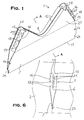
- An anti-dazzle screen 26 comprises lamellas 1 and reflector sides 2, connected to each other by means of said lamellas , which reflector sides suitably are arc-shaped or partly parabola-shaped in profile and preferably consist, like the lamellas, of polished light metal sheet or such sheet material provided with a reflecting surface coating.
- the longitudinal edges of the reflector sides which are turned downwards when used, can consist of bent covering profiles 3, whereas the edges 4, which are turned upwards when used, have an opening 5 between them designed to receive e.g. a fluorescent tube, not shown.
- the reflector sides have recesses 6, evenly distributed along the reflector sides and designed to receive the lamella ends.
- the recesses extend along the main portion of the width of the reflector sides and suitably roughly have a rectangular shape, but they suitably converge somewhat downwards in the upper part of the reflector sides and roughly are triangular, to some extent, in a concave way, in the lower part of the reflector sides.
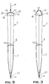
- a lamella consists of a double, mainly symmetrical sheet, in which the lower lamella half 7, which is arrow-head-shaped in profile and fills the triangular recess portion, is continuous along the length of the lamella, whereas the upper lamella half 27, which mainly is rectangular in profile, has a concaveness 8, which surrounds opening 5 at a distance, which is designed to receive a fluorescent tube or the like and which is obtained by lamella edges 9 within this area, which extend roughly perpendicular from the reflector sides to the center of the reflector in profile, where the edges meet in the shape of a soft bend 10.
- the upper longitudinal lamella side which thus is L-shaped, consists of flanges 12, which are bent towards each other at roughly 90° and constitute the two free longitudinal areas of the lamella, which suitably meet in the shape of overlappings or potential overlappings (see Figs. 3 and 5) in order to allow a compression of the lamella within this area, but the lamella can expand again thanks to its inherent elasticity due to its structure.
- the gable ends 13 of the lamellas pierce recesses 6 and the suitably somewhat rounded gable ends of the arrow-head-parts within the parts, which project in this way, are provided with through transversal holes 14, used to fasten anchor means , known per se and designed to hold the reflector in an opening in the ceiling, an outer reflector shell or the like (not shown).
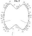
- the upper half of the lamella projects with oblong blocking tongues 15 through said recesses 6,
- the existence of these tongues or possibly only an imaginary base line 16 along each symmetry half 17 of the lamella runs approximately tangentially to the convex outer reflector side and suitably is not homogenous but disrupted by a line of notches 18, which are used as material weakenings in order to facilitate the bending into a small acute angle to the symmetry plane of the lamella of e.g. 30° of two tongues , positioned opposite each other, towards each other (see Figs. 1-3).
- the lamellas having the shape shown in Figs. 1-3, are inserted in recesses 6 of reflector sides 2, which can be done without having to move the reflector sides, change their position or the like. It is fully sufficient to utilize the structure-conditioned elasticity of the reflector sides and/or of a fixture, not shown, in order to temporarily hold the reflector sides in the same position during the assembling of the anti-dazzle screen.
- the inserting of the lamellas into two reflector sides suitably is done in a fully or partially automatic way, some type of a robot (not shown) being used to hold one or several or all of the lamellas, designed for an anti-dazzle screen.
- the lamellas are compressed in this way and their thickness is reduced, which facilitates the inserting of the lamellas into the recesses. Subsequent to the inserting the lamellas expand automatically and fill the recesses due to their inherent elasticity. A pressure is then applied in the direction indicated by arrows 19 against the initially angled tongues, the tongues taking up a steeper angle of e.g. 60° - 90° relative to the symmetry plane of the lamella and actually physically hitting each other, preferably with a certain pressure, which is propagated to the weakened area around the base line 16, the material within this area partially being squeezed out in the shape of bosses 20, which will be positioned outside the plane of the lamella sides and consequently outside the edges of the recesses.
- these edge areas preferably will be provided with some type of profiling, deformation or the like 21, which is not shown in Fig. 7 but can be used there also. It is shown in Fig. 1 a wave-shaped deformation, the wave design of which is displaced with half a division between two tongues, placed opposite each other.
- At least one of the lamella sides adjacent the arrow-head is provided with a cut 22, which coincides with the exterior side of the reflector and marks off a tongue 23, which can be bent laterally to a position on the outside of the respective reflector side (see Fig. 6).
- the outermost/lowermost arrow-head is at the lamella ends somewhat withdrawn in the longitudinal direction of the lamella in order to form a notch 24, which is used as an insertion restriction, designed to prevent, that said arrow-head penetrates all the way through the respective recess.
- the upper corner area of the lamella can be withdrawn in a similar way by means of a notch 25 in order to also prevent, that the lamella within this area can penetrate further outwards through the respective reflector side.
- a blocking tongue 15 may also be sufficient and will in that case act against the other lamella side 17 or shorter tongues may be used at each lamella side, which will act against the other lamella side, which in this areas is tongue-free.
- the tongues may also be designed with fingers, which comb into and interlock with each other like folded hands.
- the reflector sides may of course be designed in any suitable way, but in certain cases it may be necessary to mount the second reflector side, subsequent to the insertion of the lamellas, in the first one.
- alternative fastening and fixation techniques for the lamellas in the reflector sides may be used, i.e. the lamellas may be inserted deeper into the reflector sides and/or the reflector sides may lean at other angles than those shown in the drawings, e.g. to give opening 5 different widths, e.g. to receive two fluorescent tubes rather than one
Landscapes
- Engineering & Computer Science (AREA)
- General Engineering & Computer Science (AREA)
- Illuminated Signs And Luminous Advertising (AREA)
- Securing Globes, Refractors, Reflectors Or The Like (AREA)
- Diaphragms For Electromechanical Transducers (AREA)
- Manufacture, Treatment Of Glass Fibers (AREA)
- Camera Data Copying Or Recording (AREA)
- Transforming Electric Information Into Light Information (AREA)
- Threshing Machine Elements (AREA)
- Roof Covering Using Slabs Or Stiff Sheets (AREA)
- Operating, Guiding And Securing Of Roll- Type Closing Members (AREA)
- Mechanical Means For Catching Fish (AREA)
- Glass Compositions (AREA)
- Ultra Sonic Daignosis Equipment (AREA)
- Optical Elements Other Than Lenses (AREA)
- Circuit Arrangements For Discharge Lamps (AREA)
Applications Claiming Priority (2)
| Application Number | Priority Date | Filing Date | Title |
|---|---|---|---|
| SE9902677 | 1999-07-12 | ||
| SE9902677A SE518945C2 (sv) | 1999-07-12 | 1999-07-12 | Blänkskydd till en belysningsarmatur samt sätt att montera ett sådant |
Publications (3)
| Publication Number | Publication Date |
|---|---|
| EP1069372A2 true EP1069372A2 (de) | 2001-01-17 |
| EP1069372A3 EP1069372A3 (de) | 2003-09-24 |
| EP1069372B1 EP1069372B1 (de) | 2004-10-06 |
Family
ID=20416481
Family Applications (1)
| Application Number | Title | Priority Date | Filing Date |
|---|---|---|---|
| EP00114217A Expired - Lifetime EP1069372B1 (de) | 1999-07-12 | 2000-07-03 | Leuchtenraster und Montageverfahren desselben |
Country Status (7)
| Country | Link |
|---|---|
| EP (1) | EP1069372B1 (de) |
| AT (1) | ATE278910T1 (de) |
| DE (1) | DE60014518T2 (de) |
| DK (1) | DK1069372T3 (de) |
| ES (1) | ES2229997T3 (de) |
| NO (1) | NO323048B1 (de) |
| SE (1) | SE518945C2 (de) |
Citations (1)
| Publication number | Priority date | Publication date | Assignee | Title |
|---|---|---|---|---|
| EP0446317A1 (de) | 1989-10-03 | 1991-09-18 | Zumtobel Ag | Leuchtenraster. |
Family Cites Families (2)
| Publication number | Priority date | Publication date | Assignee | Title |
|---|---|---|---|---|
| US5528478A (en) * | 1995-10-04 | 1996-06-18 | Cooper Industries, Inc. | Lighting fixture having a parabolic louver |
| SE507223C2 (sv) * | 1997-04-04 | 1998-04-27 | Fagerhults Ab | Sätt att framställa ett bländskydd, en reflektor eller dylikt till en elektrisk belysningsarmatur samt ett bländskydd, en reflektor elle dylikt, som framställts enligt sättet |
-
1999
- 1999-07-12 SE SE9902677A patent/SE518945C2/sv not_active IP Right Cessation
-
2000
- 2000-06-13 NO NO20003008A patent/NO323048B1/no not_active IP Right Cessation
- 2000-07-03 DK DK00114217T patent/DK1069372T3/da active
- 2000-07-03 EP EP00114217A patent/EP1069372B1/de not_active Expired - Lifetime
- 2000-07-03 AT AT00114217T patent/ATE278910T1/de active
- 2000-07-03 ES ES00114217T patent/ES2229997T3/es not_active Expired - Lifetime
- 2000-07-03 DE DE60014518T patent/DE60014518T2/de not_active Expired - Lifetime
Patent Citations (1)
| Publication number | Priority date | Publication date | Assignee | Title |
|---|---|---|---|---|
| EP0446317A1 (de) | 1989-10-03 | 1991-09-18 | Zumtobel Ag | Leuchtenraster. |
Also Published As
| Publication number | Publication date |
|---|---|
| DE60014518T2 (de) | 2005-10-20 |
| ATE278910T1 (de) | 2004-10-15 |
| NO20003008L (no) | 2001-01-15 |
| DK1069372T3 (da) | 2004-12-27 |
| EP1069372A3 (de) | 2003-09-24 |
| DE60014518D1 (de) | 2004-11-11 |
| EP1069372B1 (de) | 2004-10-06 |
| NO20003008D0 (no) | 2000-06-13 |
| SE9902677L (sv) | 2001-01-13 |
| NO323048B1 (no) | 2006-12-27 |
| SE9902677D0 (sv) | 1999-07-12 |
| SE518945C2 (sv) | 2002-12-10 |
| ES2229997T3 (es) | 2005-05-01 |
Similar Documents
| Publication | Publication Date | Title |
|---|---|---|
| US5657598A (en) | Joint-masking device and method of assembling it | |
| EP0859892B1 (de) | Gitterrost für eine abgehängte decke | |
| CA2481722C (en) | Main tee splice | |
| RU2188286C2 (ru) | Кольцевой соединитель обрешетки (варианты) | |
| KR100403210B1 (ko) | 레버방식의 클램프 | |
| RU2365715C2 (ru) | Фиксирующий соединительный элемент | |
| JPH01250551A (ja) | サンドイッチ型壁パネル | |
| US5779380A (en) | Strip for joining components | |
| US5234199A (en) | Chain link fencing with decorative slats | |
| EP1069372B1 (de) | Leuchtenraster und Montageverfahren desselben | |
| JPS6020539B2 (ja) | パネル組立体 | |
| CA2117370A1 (en) | Clamp for paper sheets | |
| RU2194658C2 (ru) | Средства взаимной фиксации стенок для коробок | |
| JP2620927B2 (ja) | ダクト継手 | |
| JPS6233133Y2 (de) | ||
| CA1055220A (en) | Suspended ceiling system | |
| RU2173415C2 (ru) | Зажимное устройство для разъемного соединения двух профильных деталей | |
| JPH048755Y2 (de) | ||
| EP0804662B1 (de) | Gussform zum eingraben von rohren | |
| CN101326403A (zh) | 在槽形壳体与罩之间具有锁定装置的灯具 | |
| JPS6347226Y2 (de) | ||
| EP0678647A1 (de) | Verriegelungshalter für Rolläden | |
| CA1128723A (en) | Panel connectors | |
| JP3061081B2 (ja) | 照明器具 | |
| JPH077602B2 (ja) | 照明器具用ルーバ |
Legal Events
| Date | Code | Title | Description |
|---|---|---|---|
| PUAI | Public reference made under article 153(3) epc to a published international application that has entered the european phase |
Free format text: ORIGINAL CODE: 0009012 |
|
| AK | Designated contracting states |
Kind code of ref document: A2 Designated state(s): AT BE CH CY DE DK ES FI FR GB GR IE IT LI LU MC NL PT SE |
|
| AX | Request for extension of the european patent |
Free format text: AL;LT;LV;MK;RO;SI |
|
| 17P | Request for examination filed |
Effective date: 20010126 |
|
| PUAL | Search report despatched |
Free format text: ORIGINAL CODE: 0009013 |
|
| AK | Designated contracting states |
Kind code of ref document: A3 Designated state(s): AT BE CH CY DE DK ES FI FR GB GR IE IT LI LU MC NL PT SE |
|
| AX | Request for extension of the european patent |
Extension state: AL LT LV MK RO SI |
|
| 17Q | First examination report despatched |
Effective date: 20031120 |
|
| GRAP | Despatch of communication of intention to grant a patent |
Free format text: ORIGINAL CODE: EPIDOSNIGR1 |
|
| AKX | Designation fees paid |
Designated state(s): AT BE CH CY DE DK ES FI FR GB GR IE IT LI LU MC NL PT SE |
|
| GRAS | Grant fee paid |
Free format text: ORIGINAL CODE: EPIDOSNIGR3 |
|
| GRAA | (expected) grant |
Free format text: ORIGINAL CODE: 0009210 |
|
| AK | Designated contracting states |
Kind code of ref document: B1 Designated state(s): AT BE CH CY DE DK ES FI FR GB GR IE IT LI LU MC NL PT SE |
|
| REG | Reference to a national code |
Ref country code: GB Ref legal event code: FG4D |
|
| REG | Reference to a national code |
Ref country code: CH Ref legal event code: EP |
|
| REG | Reference to a national code |
Ref country code: IE Ref legal event code: FG4D |
|
| REF | Corresponds to: |
Ref document number: 60014518 Country of ref document: DE Date of ref document: 20041111 Kind code of ref document: P |
|
| REG | Reference to a national code |
Ref country code: CH Ref legal event code: NV Representative=s name: INTERPAT LAW AG |
|
| PG25 | Lapsed in a contracting state [announced via postgrant information from national office to epo] |
Ref country code: GR Free format text: LAPSE BECAUSE OF FAILURE TO SUBMIT A TRANSLATION OF THE DESCRIPTION OR TO PAY THE FEE WITHIN THE PRESCRIBED TIME-LIMIT Effective date: 20050106 Ref country code: SE Free format text: LAPSE BECAUSE OF FAILURE TO SUBMIT A TRANSLATION OF THE DESCRIPTION OR TO PAY THE FEE WITHIN THE PRESCRIBED TIME-LIMIT Effective date: 20050106 |
|
| REG | Reference to a national code |
Ref country code: ES Ref legal event code: FG2A Ref document number: 2229997 Country of ref document: ES Kind code of ref document: T3 |
|
| PG25 | Lapsed in a contracting state [announced via postgrant information from national office to epo] |
Ref country code: CY Free format text: LAPSE BECAUSE OF FAILURE TO SUBMIT A TRANSLATION OF THE DESCRIPTION OR TO PAY THE FEE WITHIN THE PRESCRIBED TIME-LIMIT Effective date: 20050703 Ref country code: LU Free format text: LAPSE BECAUSE OF NON-PAYMENT OF DUE FEES Effective date: 20050703 |
|
| PG25 | Lapsed in a contracting state [announced via postgrant information from national office to epo] |
Ref country code: IE Free format text: LAPSE BECAUSE OF NON-PAYMENT OF DUE FEES Effective date: 20050704 |
|
| PG25 | Lapsed in a contracting state [announced via postgrant information from national office to epo] |
Ref country code: MC Free format text: LAPSE BECAUSE OF NON-PAYMENT OF DUE FEES Effective date: 20050731 |
|
| PLBE | No opposition filed within time limit |
Free format text: ORIGINAL CODE: 0009261 |
|
| STAA | Information on the status of an ep patent application or granted ep patent |
Free format text: STATUS: NO OPPOSITION FILED WITHIN TIME LIMIT |
|
| ET | Fr: translation filed | ||
| 26N | No opposition filed |
Effective date: 20050707 |
|
| REG | Reference to a national code |
Ref country code: IE Ref legal event code: MM4A |
|
| PG25 | Lapsed in a contracting state [announced via postgrant information from national office to epo] |
Ref country code: PT Free format text: LAPSE BECAUSE OF NON-PAYMENT OF DUE FEES Effective date: 20050306 |
|
| PG25 | Lapsed in a contracting state [announced via postgrant information from national office to epo] |
Ref country code: IT Free format text: LAPSE BECAUSE OF NON-PAYMENT OF DUE FEES Effective date: 20100703 |
|
| PGRI | Patent reinstated in contracting state [announced from national office to epo] |
Ref country code: IT Effective date: 20110616 |
|
| PGFP | Annual fee paid to national office [announced via postgrant information from national office to epo] |
Ref country code: CH Payment date: 20120613 Year of fee payment: 13 |
|
| PGFP | Annual fee paid to national office [announced via postgrant information from national office to epo] |
Ref country code: BE Payment date: 20120511 Year of fee payment: 13 Ref country code: FR Payment date: 20120604 Year of fee payment: 13 |
|
| PGFP | Annual fee paid to national office [announced via postgrant information from national office to epo] |
Ref country code: ES Payment date: 20120726 Year of fee payment: 13 Ref country code: IT Payment date: 20120727 Year of fee payment: 13 |
|
| PGFP | Annual fee paid to national office [announced via postgrant information from national office to epo] |
Ref country code: AT Payment date: 20120724 Year of fee payment: 13 |
|
| BERE | Be: lapsed |
Owner name: *FAGERHULTS BELYSNING A.B. Effective date: 20130731 |
|
| REG | Reference to a national code |
Ref country code: CH Ref legal event code: PL |
|
| REG | Reference to a national code |
Ref country code: AT Ref legal event code: MM01 Ref document number: 278910 Country of ref document: AT Kind code of ref document: T Effective date: 20130703 |
|
| REG | Reference to a national code |
Ref country code: FR Ref legal event code: ST Effective date: 20140331 |
|
| PG25 | Lapsed in a contracting state [announced via postgrant information from national office to epo] |
Ref country code: CH Free format text: LAPSE BECAUSE OF NON-PAYMENT OF DUE FEES Effective date: 20130731 Ref country code: LI Free format text: LAPSE BECAUSE OF NON-PAYMENT OF DUE FEES Effective date: 20130731 Ref country code: BE Free format text: LAPSE BECAUSE OF NON-PAYMENT OF DUE FEES Effective date: 20130731 |
|
| PG25 | Lapsed in a contracting state [announced via postgrant information from national office to epo] |
Ref country code: AT Free format text: LAPSE BECAUSE OF NON-PAYMENT OF DUE FEES Effective date: 20130703 Ref country code: FR Free format text: LAPSE BECAUSE OF NON-PAYMENT OF DUE FEES Effective date: 20130731 Ref country code: IT Free format text: LAPSE BECAUSE OF NON-PAYMENT OF DUE FEES Effective date: 20130703 |
|
| REG | Reference to a national code |
Ref country code: ES Ref legal event code: FD2A Effective date: 20141010 |
|
| PG25 | Lapsed in a contracting state [announced via postgrant information from national office to epo] |
Ref country code: ES Free format text: LAPSE BECAUSE OF NON-PAYMENT OF DUE FEES Effective date: 20130704 |
|
| PGFP | Annual fee paid to national office [announced via postgrant information from national office to epo] |
Ref country code: NL Payment date: 20150715 Year of fee payment: 16 |
|
| PGFP | Annual fee paid to national office [announced via postgrant information from national office to epo] |
Ref country code: FI Payment date: 20150702 Year of fee payment: 16 Ref country code: DK Payment date: 20150728 Year of fee payment: 16 Ref country code: GB Payment date: 20150714 Year of fee payment: 16 Ref country code: DE Payment date: 20150714 Year of fee payment: 16 |
|
| REG | Reference to a national code |
Ref country code: DE Ref legal event code: R082 Ref document number: 60014518 Country of ref document: DE Representative=s name: PATENTANWAELTE OLBRICHT, BUCHHOLD, KEULERTZ PA, DE |
|
| REG | Reference to a national code |
Ref country code: DE Ref legal event code: R119 Ref document number: 60014518 Country of ref document: DE |
|
| REG | Reference to a national code |
Ref country code: DK Ref legal event code: EBP Effective date: 20170131 |
|
| REG | Reference to a national code |
Ref country code: NL Ref legal event code: MM Effective date: 20160801 |
|
| GBPC | Gb: european patent ceased through non-payment of renewal fee |
Effective date: 20160703 |
|
| PG25 | Lapsed in a contracting state [announced via postgrant information from national office to epo] |
Ref country code: NL Free format text: LAPSE BECAUSE OF NON-PAYMENT OF DUE FEES Effective date: 20160801 Ref country code: DE Free format text: LAPSE BECAUSE OF NON-PAYMENT OF DUE FEES Effective date: 20170201 Ref country code: FI Free format text: LAPSE BECAUSE OF NON-PAYMENT OF DUE FEES Effective date: 20160703 |
|
| PG25 | Lapsed in a contracting state [announced via postgrant information from national office to epo] |
Ref country code: GB Free format text: LAPSE BECAUSE OF NON-PAYMENT OF DUE FEES Effective date: 20160703 |
|
| PG25 | Lapsed in a contracting state [announced via postgrant information from national office to epo] |
Ref country code: DK Free format text: LAPSE BECAUSE OF NON-PAYMENT OF DUE FEES Effective date: 20160731 |