EP1069358A2 - Elektromagnetisches Ventil - Google Patents
Elektromagnetisches Ventil Download PDFInfo
- Publication number
- EP1069358A2 EP1069358A2 EP00115113A EP00115113A EP1069358A2 EP 1069358 A2 EP1069358 A2 EP 1069358A2 EP 00115113 A EP00115113 A EP 00115113A EP 00115113 A EP00115113 A EP 00115113A EP 1069358 A2 EP1069358 A2 EP 1069358A2
- Authority
- EP
- European Patent Office
- Prior art keywords
- valve
- solenoid
- pressure
- pressure response
- response means
- Prior art date
- Legal status (The legal status is an assumption and is not a legal conclusion. Google has not performed a legal analysis and makes no representation as to the accuracy of the status listed.)
- Withdrawn
Links
- 230000004044 response Effects 0.000 claims description 38
- 238000000926 separation method Methods 0.000 claims description 3
- 230000008602 contraction Effects 0.000 claims description 2
- 239000012530 fluid Substances 0.000 description 17
- 238000001816 cooling Methods 0.000 description 11
- 230000007423 decrease Effects 0.000 description 11
- 230000008859 change Effects 0.000 description 10
- 230000003247 decreasing effect Effects 0.000 description 10
- 239000003507 refrigerant Substances 0.000 description 7
- 230000002093 peripheral effect Effects 0.000 description 6
- 238000010586 diagram Methods 0.000 description 4
- 238000004378 air conditioning Methods 0.000 description 3
- 238000004891 communication Methods 0.000 description 3
- 238000007599 discharging Methods 0.000 description 2
- 230000004907 flux Effects 0.000 description 2
- 230000009471 action Effects 0.000 description 1
- 239000000470 constituent Substances 0.000 description 1
- 238000006073 displacement reaction Methods 0.000 description 1
- 238000005516 engineering process Methods 0.000 description 1
- 230000002349 favourable effect Effects 0.000 description 1
- 238000003754 machining Methods 0.000 description 1
- 238000012986 modification Methods 0.000 description 1
- 230000004048 modification Effects 0.000 description 1
- 230000007935 neutral effect Effects 0.000 description 1
Images


Classifications
-
- F—MECHANICAL ENGINEERING; LIGHTING; HEATING; WEAPONS; BLASTING
- F16—ENGINEERING ELEMENTS AND UNITS; GENERAL MEASURES FOR PRODUCING AND MAINTAINING EFFECTIVE FUNCTIONING OF MACHINES OR INSTALLATIONS; THERMAL INSULATION IN GENERAL
- F16K—VALVES; TAPS; COCKS; ACTUATING-FLOATS; DEVICES FOR VENTING OR AERATING
- F16K31/00—Actuating devices; Operating means; Releasing devices
- F16K31/02—Actuating devices; Operating means; Releasing devices electric; magnetic
- F16K31/06—Actuating devices; Operating means; Releasing devices electric; magnetic using a magnet, e.g. diaphragm valves, cutting off by means of a liquid
- F16K31/0644—One-way valve
- F16K31/0655—Lift valves
-
- F—MECHANICAL ENGINEERING; LIGHTING; HEATING; WEAPONS; BLASTING
- F16—ENGINEERING ELEMENTS AND UNITS; GENERAL MEASURES FOR PRODUCING AND MAINTAINING EFFECTIVE FUNCTIONING OF MACHINES OR INSTALLATIONS; THERMAL INSULATION IN GENERAL
- F16K—VALVES; TAPS; COCKS; ACTUATING-FLOATS; DEVICES FOR VENTING OR AERATING
- F16K31/00—Actuating devices; Operating means; Releasing devices
- F16K31/02—Actuating devices; Operating means; Releasing devices electric; magnetic
- F16K31/06—Actuating devices; Operating means; Releasing devices electric; magnetic using a magnet, e.g. diaphragm valves, cutting off by means of a liquid
- F16K31/0644—One-way valve
- F16K31/0668—Sliding valves
Definitions
- the present invention relates to a solenoid valve. More specifically, the invention relates to technology for improving the operating stability and control characteristics of the solenoid valve.
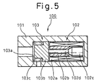
- Fig. 5 is a diagram schematically illustrating the fundamental constitution of a conventional solenoid valve.
- the solenoid valve 100 is constituted by concentrically arranging a solenoid unit 102 and a valve unit 103 in a cylindrical valve body 101.
- the solenoid unit 102 includes a coil 102a that generates magnetic flux upon being supplied with an electric current, a center post 102b for converging the magnetic flux generated by the coil 102a, a plunger 102c that is moved in the axial direction by being magnetically pulled by the center post 102b, and a rod 102d that transmits the driving force of the plunger 102c.
- the valve unit 103 includes a valve 103b that comes in contact with, and separates away from, the valve seat 103a.
- the valve 103b is urged by a spring 103c in a direction in which it opens, and is urged by the rod 102d when an electric current is supplied to the coil 102a to move in a direction in which it closes, thereby to control the fluid.
- the solenoid valves of this kind can be roughly divided into those which turn on or off the fluid that is to be controlled in a state where the valve is either opened or closed, and those which proportionally control (current - pressure or flow rate) the pressure and flow rate by varying the opening area of the valve unit by changing the stroke position of the valve (plunger) depending upon the applied voltage.
- Fig. 5 illustrates a valve, that is suited for accomplishing proportional control, in which the opposing surfaces of the center post 102b and the plunger 102c have conical shapes to obtain such characteristics that the thrust remains constant, for a given electric current, even though the plunger undergoes a movement.
- Solenoid valves of the on/off control type and of the proportional control type are operated under the conditions described below.
- the on/off control solenoid must be turned off with a current smaller than an open current (valve-opening current in the case of Fig. 5) and must be turned on with a current larger than an operation current (valve-closing current).
- the relationship between the spring 103c and the attractive force of the solenoid must be such that the inclination (Ksol) of the attractive force of the solenoid > spring constant (Ksp), as shown in Fig. 6.
- the spring constant shows the inclination of the spring force.
- Fig. 6 is a graph illustrating a relationship between the load applied to the valve and the valve position in the on/off control solenoid, wherein the abscissa represents the stroke (moving amount) of the valve and the ordinate represents the load formed by the spring force depending on the stroke position of the valve and the solenoid attractive force (the directions are opposite to each other).
- the solenoid attractive force is greater than the spring force, the valve moves toward the on (closing) side and in the opposite case, the valve moves toward the off (opening) side.
- the solenoid attractive forces S0 to S3 vary depending upon the current flowing into the coil. Described below are the operation conditions with each of the attractive forces.
- the spring constant shows the inclination of the spring force.
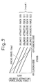
- Fig. 7 is a graph illustrating, as in Fig. 6, a relationship between the load exerted on the valve and the valve position in the proportional control solenoid.
- an intersecting point of the solenoid attractive force and the spring force is a balanced position, and the amount of stroke of the valve at this moment is the valve-opening amount.
- the solenoid attractive forces S0 to S3 vary depending upon the electric current supplied to the coil. Described below are the operation conditions with each of the attractive forces.
- the on/off control solenoid and the proportional control solenoid have the above-mentioned relationships of the inclination of the solenoid attractive force and the spring constant, and are used for different purposes.
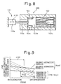
- a solenoid valve 200 equipped with an automatic pressure-adjusting function, in which a load, produced by pressure response means that responds to the pressure of the control fluid and to the pressure such as atmospheric pressure, is exerted on the valve to change the stroke position depending upon the pressure.
- Fig. 8 is a schematic diagram illustrating the constitution of this solenoid valve 200 which is equipped with a sealed bellows assembly 110 (pressure response means) of which the interior is evacuated or has a predetermined pressure in addition to the constitution of the solenoid valve 100 of Fig. 5.
- the bellows assembly 110 changes its length (direction of an arrow A101) depending upon a change in the compressive force caused by a pressure exerted on the exterior of the bellows 110a, and gives a load in the axial direction that varies depending upon the pressure in a state where the rod 110b is connected to the valve 103b.
- the solenoid valve 200 is used, for example, as a capacity control valve of a variable capacity-type compressor employed in an air conditioning system of a vehicle.
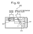
- the variable capacity-type compressor may be a swash plate compressor which, as shown in Fig. 10, compresses a refrigerant by changing, into a reciprocal motion of the piston 303, the displacement in the axial direction of a swash plate 302 set to swing at a predetermined angle of inclination relative to a rotary shaft 301 which receives the rotational drive force from the engine of the vehicle.
- the stroke of the piston 303 is determined depending upon the angle ⁇ of inclination of the swash plate 302, and the amount of discharge of the refrigerant from the compressor 300 is determined per revolution of the rotary shaft 301.
- the angle ⁇ of inclination of the swash plate 302 is secured, therefore, the cooling ability varies depending upon a change in the rotational speed that is input.
- the length of the bellows 110a is varied depending upon the suction pressure Ps, so that the urging force of the bellows assembly 110 is transmitted to the valve 103b.
- the valve 103b is opened and closed, and the crank-case pressure Pc is controlled and the angle ⁇ of inclination of the swash plate 302 is changed to obtain a desired suction pressure Ps.
- the bellows assembly 110 opens and closes the valve 103b by a small amount such that the suction pressure Ps is balanced with a predetermined constant pressure (constant blow-out temperature of the cooling air), whereby the angle ⁇ of inclination of the swash plate 302 is changed to control the amount of discharging the refrigerant of the compressor 300.
- the angle ⁇ of inclination of the swash plate 302 of the compressor 300 is determined by the balancing of discharge pressure Pd of the compressor 300, crank-case pressure Pc and suction pressure PS. Therefore:
- the ports at the above-mentioned pressures Pd, Pc, Ps of the compressor 300 and the solenoid valve 200 are connected as represented by a circuit shown in Fig. 12.
- the crank-case pressure Pc is connected to the suction pressure Ps through an orifice 305 in the compressor 300.
- the balancing control for accomplishing a predetermined constant suction pressure Ps is to adjust the suction pressure Ps by controlling the angle ⁇ of inclination of the swash plate 302, such as moving the bellows assembly 110 toward the extending side to open the valve 103b when the suction pressure Ps is small and moving the bellows assembly 110 toward the contracting side to close the valve 103b when the suction pressure Ps IS large, in order to accomplish the predetermined suction pressure Ps.
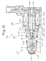
- Fig. 13 illustrates a solenoid valve 400 which is a concrete example of the conventional solenoid valve 200 shown in Fig. 8.
- the solenoid valve 400 is roughly constituted by a solenoid unit 402, a valve unit 403 and a bellows assembly 410.
- the solenoid unit 402 is arranged at one end of a valve body 404 of nearly a cylindrical shape like the one that is generally used in the prior art.
- An electric current is supplied to a coil 402a to generate a magnetic force, whereby a plunger 402b is attracted by a center post 402c to generate an urging force (solenoid attractive force) of a magnitude corresponding to the current.
- the valve unit 403 has a valve 403b in a valve chamber 403a formed in a valve body 404, the valve 403b being allowed to move in the axial direction in the valve chamber 403a so as to come in contact with, and separate away from, a valve seat 403c opened in the valve chamber 403a. Further, the valve 403b is urged by a spring 403d which is an urging means in a direction in which it opens, and is formed integrally with a rod 402d of the solenoid side.
- a port 403e is connected to the valve chamber 403a of the valve unit 403, and a port 403f is connected to the valve seat 403c.
- the port 403f is guiding the crank chamber pressure Pc to the plunger chamber 402e through a communication passage 404a.
- the bellows assembly 410 is arranged at the other end of the side opposite to the solenoid unit 402 of the valve body 404.
- the bellows assembly 410 includes a sealed bellows core 410a of which the interior is evaluated or has a predetermined pressure, a stopper 410b for holding both ends of the bellows core 410a, and a spring 410d that extends inside the holder 410c and the bellows core 410a to produce an urging force and to prevent collapse.
- the urging force in the opening direction is given to the valve 403b when the bellows assembly extends in response to the pressure (suction pressure Ps) surrounding the bellows core 410a in excess of a predetermined length (when the suction pressure Ps has dropped) via the rod 410f slidably held by the holder unit 410e.
- the bellows assembly 410 does not engage with the valve 403b throughout the whole stroke of the valve 403b to urge it, but is so constituted that at least the rod 410f and the valve 403b are brought into engagement from the position where the valve 403b is closed up to a position halfway in the stroke in response to the suction pressure Ps. If the valve-opening amount of the valve 403b is maintained, the bellows assembly 410 may be brought into engagement throughout the whole stroke.
- the compressor controlled by the solenoid valve 200 or the solenoid valve 400 equipped with the automatic pressure-adjusting function is generally provided with an electromagnetic clutch which is turned on and off, to transmit the driving power to the rotary shaft that rotates the swash plate, i.e., to drive the compressor or not to transmit the driving power thereto, i.e., not to drive the compressor.
- the compressor is turned on and off by opening and closing the valve of the solenoid valve.
- the solenoid valve must possess two functions, i.e., the function for opening and closing (on/off controlling) the valve for turning the compressor on and off, and a function of proportional control for adjusting the suction pressure Ps.
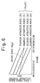
- Fig. 9 is a graph illustrating a relationship between the load exerted on the valve and the valve position in the solenoid valve 200 equipped with a function for automatically adjusting the pressure.
- an intersecting point of the solenoid attractive force between the solid lines HI and LO
- the bellows force and spring force is a balance position, and the amount of stroke of the valve at this moment is a valve-opening amount.
- the load given to the valve changes depending upon a change in the external pressure (suction pressure Ps) and, hence, Kb + Ksp undergoes parallel translation depending upon the external pressures (P0 (low pressure) to P3(high pressure)), and the intersecting position with the solenoid attractive force generated by predetermined current becomes a valve-opening amount.
- the automatic pressure adjustment is accomplished in the region R101 of the stroke on the side on where the valve is closed and in the region R102 on the side on where the valve is opened with respect to the solenoid attractive forces HI and LO.
- the solenoid attractive force must be equal to, or larger than, HI to close the valve by the on/off control. Therefore, the solenoid must produce a large attractive force in a state where the center post and the plunger are separated away from each other.
- the valve may be balanced at an intermediate position, causing a problem with the solenoid that executes the on/off control operation.
- the rod 410f engaged with the bellows assembly 410, the rod 402d on the solenoid side formed integrally with the valve 403b, and the plunger 402b are separately constituted.
- the rod 410f and the rod 402d of the solenoid side are held by using clearance seals CS401, CS402 (precise slide fitting) enabling the members to slide in the axial direction and preventing the leakage of the control fluid.
- the plunger 402b and the plunger chamber 402e must be precisely fitted together, requiring a highly precise machining in addition to those for the rod 410f and the rod 402d of the solenoid side.
- clearance seals CS401, CS402 and of the plunger 402b could cause a sliding hysteresis during the operation of the solenoid valve 400.
- the clearance seals CS01, CS402 could cause a fluid lock that may produce a large slide resistance.
- a communication passage 404a must be provided to guide the crank chamber pressure Pc to the plunger chamber 402e.
- the present invention was accomplished in order to solve the problem inherent in the above-mentioned prior art, and its object is to provide a solenoid valve which decreases the slide hysteresis and fluid locking in the slide portions at the time when the valve is driven in the valve control operation, and assures a stable and highly reliable operation.
- the invention further provides a solenoid valve which exhibits spring constants in the solenoid valve, inclination of attractive force of the solenoid, and is capable of efficiently realizing the on/off control function and the proportional control function.
- the solenoid valve of the invention comprises:
- valve and the plunger are constituted as a unitary structure which is slidably supported at both ends, i.e., supported at a portion on the side of the pressure response means and at the plunger at both ends of the unitary structure, decreasing the sliding resistance and realizing stable operation.
- Fig. 1 is a view illustrating the cross-sectional constitution of a solenoid valve 1 of a first embodiment to which the present invention is adapted.
- the solenoid valve 1 is used for controlling the suction pressure Ps of a variable capacity pump (same as the compressor 300 described in the prior art) used in, for example, an air conditioning system of a vehicle, and is suitably employed for a compressor of the clutchless type that is controlled to be turned on and off by the solenoid valve 1.
- the suction pressure Ps is controlled by controlling the discharge pressure Pd of the variable capacity pump and the crank chamber pressure Pc by opening and closing a valve unit 3 by utilizing a bellows assembly 10 which is a pressure response means that responds to the suction pressure Ps.
- the solenoid valve 1 is constituted by a solenoid unit 2, the valve unit 3 and the bellows assembly 10.
- the solenoid unit 2 is disposed at one end of a cylindrical valve body 4, generates a magnetic force when an electric current is supplied to a coil 2a to attract a plunger 2b by a center post 2c, thereby to produce an urging force (solenoid attractive force) of a magnitude corresponding to the electric current.
- the opposing surfaces of the plunger 2b and the center post 2C have conical shapes to suppress a change in the thrust for each of the current levels, despite motion of the plunger, to accomplish a favorable proportional control.
- the plunger 2b is slidably supported by the inner peripheral surface of the sleeve 2d, and smoothly slides in the axial direction along the inner peripheral surface of the sleeve 2d without play.
- the valve unit 3 has a valve 3b in a valve chamber 3a formed in the valve body 4, the valve 3b being allowed to move in the axial direction in the valve chamber 3a so as to come into contact with, and to separate away from, a valve seat 3c opened in the valve chamber 3a.
- the valve 3b is urged in a direction in which it is opened by a spring 3d, which is an urging means, via a valve rod 5 that will be described later.
- a port 3e that penetrates through the peripheral wall of the valve body 4 is connected to the valve chamber 3a of the valve unit 3, and a port 3f is connected to the valve seat 3c.
- the discharge pressure Pd of the variable capacity pump is introduced into the port 3f, and a crank chamber pressure PC obtained by controlling the discharge pressure Pd through the valve unit 3 is produced from the port 3e.
- the valve 3b controls the pressure/flow rate depending upon the distance between the valve seat 3c and an end surface 5b facing a small-diameter portion 5a formed by contracting the diameter of part of the central portion of the valve rod which is a unitary structure slidably arranged in the inner cylindrical portion of the valve body 4.
- the valve rod 5 has a solenoid-side rod 5c which is a connection member on the side of the solenoid 2 away from the valve 3b.
- the solenoid-side rod 5c penetrates through the inner cylindrical portion of the center post 2c to form an annular gap 6 (clearance) and is fitted and secured at its end 5d to the plunger 2b.
- the valve rod 5 further has a bellows-side rod 5e which is a connection member on the side of the pressure response means close to the bellows assembly 10 and away from the valve 3b.
- the bellows-side rod 5e is slidably supported (clearance seal by accurate slide fitting) by the internal cylindrical portion 4a of the valve body 4 as a slide support, and the bellows-side rod 5e smoothly slides along the inner peripheral surface of the inner cylindrical portion 4a, in the axial direction, without play.
- Annular grooves 5f are formed in the outer peripheral surface of the bellows-side rod 5e to suppress the fluid locking at the clearance seal.
- the shape and number of the annular grooves 5f may be suitably set so that the transverse force (pressure in the radial direction/eccentric direction) exerted on the land portion will not affect the motion in the axial direction.
- the bellows assembly 10 is disposed at the other end on the side opposite to the solenoid portion 2 of the valve body 4.
- the bellows assembly 10 includes a sealed bellows core 10a of which the interior is evacuated or has a predetermined pressure, a stopper 10b for holding both ends of the bellows core 10a, and a spring 10d which extends in the holder 10c and in the bellows core 10a to give an urging force to prevent the collapse.
- Reference numeral 10f denotes a holder spring which urges the holder 10c of the bellows assembly 10 toward the stopper 10b and holds the bellows assembly 10 by pushing it onto a recessed portion of a cover member 10g.
- the holder spring 10f and the recessed portion of the cover member 10g work as a holder means for holding the extension/contraction passage of the bellows assembly 10 in position relative to the valve 3b.
- the valve 3b is urged to move in the direction in which it opens when the bellows core 10a extends or contracts in response to the ambient pressure (suction pressure Ps), and is extended by more than a predetermined length (when the suction pressure Ps has dropped) via the bellows-side rod 5e that is slidably held by the holding portion 10e.
- the bellows assembly 10 does not come into engagement with the valve 3b to urge it throughout the whole opening/closing stroke of the valve 3b. Instead, the bellows-side rod 5e comes into engagement with the holding portion 10e in response to the suction pressure Ps up to at least a position halfway in the opening/closing stroke from the position at where the valve 3b is closed.
- the bellows assembly 10 does not engage with the valve 3b up to a position where the valve 3b is fully opened from the position halfway in the opening/closing stroke. If the valve-opening amount of the valve 3b is maintained, then, it may be brought into engagement throughout the whole stroke.
- the valve rod 5 includes the valve 3b as well as the solenoid-side rod 5c and the bellows-side rod 5e on both sides thereof, and the solenoid-side rod 5c is a unitary structure being connected to the plunger 2b. Therefore, the valve rod 5 is supported at two points at its both ends by the inner peripheral surface of the sleeve 2d and by the inner cylindrical portion 4a of the valve body 4, and stably operates with a decreased slide resistance.
- the number of parts can be decreased, the assembling efficiency is improved, and the cost can be decreased.
- annular gap 6 is formed between the solenoid-side rod 5c of the valve rod 5 and the inner periphery of the center post 2c, whereby there is no slide motion between the solenoid-side rod 5c and the center post 2c decreasing the slide resistance.
- the annular gap 6 serves as a fluid communication passage assisting smooth motion of the plunger 2b in the plunger chamber.
- the solenoid valve 1 When the spring constant of the spring 3d is denoted by Ksp, the inclination of the attractive force of the solenoid unit 2 by Ksol, and the spring constant of the bellows assembly 10 by Kb (inclusive of the urging force by the holder spring 10f), the solenoid valve 1 is so set as to establish the following relationships, Kb + Ksp > Ksol Ksol > Ksp
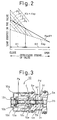
- Fig. 2 is a graph illustrating a relationship between the load exerted on the valve 3b and the position of the valve 3b, wherein the abscissa represents the opening/closing stroke (moving amount) of the valve 3b and the ordinate represents the load exerted on the valve 3b depending upon the stroke positions.
- the position halfway in the opening/closing stroke is a position where there is substantially no engaging relationship between the valve 3b and the bellows assembly 10.
- valve 3b In the region R1 where three loads are exerted on the valve 3b, the valve 3b is opened and closed in a proportional manner based upon the pressure exerted on the bellows assembly 10.
- the bellows assembly 10 undergoes a parallel translation Kb + Ksp (broken lines) depending upon the external pressure (P0 (low pressure) to P4 (high pressure)), and positions (black dots in Fig. 2) intersecting the solenoid attractive force (solid line) produced by a predetermined current are those positions where the valve 3b opens.
- the solenoid attractive force exceeds the urging force of the spring 3d over a range from the position where the valve is fully opened to a position halfway in the opening/closing stroke due to the relationship Ksol > Ksp when the solenoid attractive force exceeds the urging force of the spring 3d at the position where the valve is fully opened, and the valve 3b moves at once up to the position halfway in the opening/closing stroke, executing the open/close control operation based upon the on/off control.
- the solenoid attractive force at the position where the valve is fully opened needs not be set to be large relative to the load of the spring 3d at the same position, and the solenoid can be realized in a small size to suppress the consumption of electric current.
- the solenoid attractive force can be changed by an electric current that is supplied, and has been adjusted to a predetermined value to exhibit desired output characteristics that meet the value Kb + Ksp.
- the bellows assembly 10 of the solenoid valve 1 receives the suction pressure Ps.
- the suction pressure Ps increases, the bellows core 10a contracts toward the left in the drawing.
- the suction pressure Ps decreases, the bellows core 10a extends toward the right in the drawing.
- crank chamber pressure Pc fed from the port 3e is adjusted to adjust the output of the variable capacity pump and, thus, the suction pressure Ps of the variable capacity pump is automatically adjusted.
- the angle ⁇ of inclination of the swash plate 302 must be increased.
- the valve 3b of the solenoid valve 1 must be closed to decrease the crank chamber pressure Pc.
- the solenoid valve 1 In the control operation by changing the attractive force of the solenoid valve 1, the solenoid valve 1 maintains the relationship Ksol > Ksp in the region R2 from the valve-opening side up to a position halfway in the opening/closing stroke of the valve 3b. At the moment when the attractive force of the solenoid exceeds the urging force of the spring 3d at the position where the valve is fully opened, therefore, the valve 3b moves at once from the position where the valve is fully opened up to a position halfway in the stroke where the valve 3b and the bellows assembly 10 come into engagement, thereby to execute the open/close control operation.
- valve-closing operation in which the valve 3b moves from the valve-opening side up to a position halfway in the stroke, is quickly accomplished to enhance the response of the compressor at the start of its operation.
- the valve 3b in the solenoid valve 1 stays in a state (balance control) where the urging force of the spring 3d, the attractive force of the solenoid and the urging force of the bellows assembly 10 are balanced, to control the flow rate of the fluid.
- valve 3b in the solenoid valve 1 is often closed when the bellows core 10a is contracted leftward in the drawing due to a rise in the suction pressure Ps or when the attractive force of the solenoid valve 1 is increased.
- crank chamber pressure Pc becomes equal to the Suction pressure Ps through the orifice 305, and the angle ⁇ of inclination of the swash plate 302 becomes almost 0 due to the resilient force of a spring (not shown) that works to decrease the angle of inclination.
- the solenoid valve 1 When incorporated in the compressor, the solenoid valve 1 operates as described above to efficiently execute the two control operations, i.e., a proportional control operation and an on/off control operation depending upon the pressure of the fluid that is to be controlled.
- the embodiment employs separation/connection means in which the holding portion 10e and the bellows-side rod 5e are slidably fitted together, and the urging force of the bellows assembly 10 is given to the bellows-side rod 5e only when their opposing surfaces are in contact with each other. This prevents the generation of a force that urges the valve 3b in the direction in which it closes when the bellows assembly 10 is contracted in excess of a state where the valve 3b is closed.
- the bellows assembly 10 is held relative to the cover member 10g while being urged by the holder spring 10h, which is an urging member, in the direction in which it opens, thereby to absorb the extension of the bellows assembly 10.
- the holder spring 10f shown in Fig. 1 is not necessary.
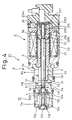
- Fig. 4 is a view illustrating the cross-sectional constitution of a solenoid valve 21 according to a second embodiment.
- the constituent elements same as those of the first embodiment are denoted by the same reference numerals, and the description refers to that of the first embodiment.
- the solenoid valve 21 is suited for the compressor with clutch that does not require on/off control function for the solenoid valve.
- the solenoid valve 21 has a characteristic constitution in that a spring 23d which is means for urging the valve 3b urges the valve rod 5 in a direction in which the valve 3b closes.
- an end 22b1 of the plunger 22b on the side of the center post 2c is fitted and secured to the end 5d of the solenoid-side rod 5c, and an inner-diameter portion 22b3 larger than the outer diameter of the end 5d is formed from an end surface 22b2 facing the bottom 2d1 of the sleeve 2d thereby to form an annular groove 22b4.
- a spring 23d is held while being compressed between the annular groove 22b4 and the bottom 2d1 of the sleeve 2d to urge the valve rod 5.
- a response to the suction pressure Ps is obtained by utilizing a change in the suction pressure Ps even in a state where no electric current is supplied to the solenoid unit 2, and the valve 3b is balance-controlled even when no electric current is supplied to the solenoid unit 2.
- the valve-opening state can be set over a range of from zero solenoid attractive force F through up to a maximum of electric current, to efficiently utilize the solenoid attractive force F.
- the valve in the solenoid valve stably operates with decreased slide resistance, making it possible to obtain a solenoid valve that operates highly reliably.
- annular gap is formed between the inner circumference of the center post and the outer circumference of the connection member of the side of the solenoid, there is no slide motion between the connection member on the side of the solenoid and the center post, contributing to decreasing the slide resistance.
- the annular gap is used as the fluid passage assisting the smooth motion of the plunger in the plunger chamber.
- Provision of the annular grooves in the outer periphery of the connection member on the side of the pressure response means prevents fluid locking between the connection member on the side of the pressure response means and the slide support unit.
- the valve Upon specifying the engaging state between the pressure response means and the valve, the valve is positioned on the valve-opening side in the state where no current is supplied to the solenoid.
- the valve moves at once from the position where the valve is fully opened up to a position halfway in the stroke where the valve engages with the pressure response means when the attractive force of the solenoid exceeds the urging force of the urging means at the position where the valve is fully opened due to the relationship Ksol > Ksp, so that the valve is opened and closed by the on/off control operation. From the position halfway in the stroke up to the valve-closing side, the valve is opened and closed by the proportional control operation depending upon the pressure.
- the attractive force of the solenoid at the position where the valve is fully opened need not be set to be large relative to the load of the urging means at the same position, and the solenoid can be realized in a small size and the consumption of electric current can be suppressed.
- the valve since the valve is urged by the urging means in the direction in which it closes, the valve can be balance-controlled even when no current is supplied to the solenoid, and the attractive force of the solenoid can be set from 0 up to a state where the valve is opened with a maximum electric current.
- the attractive force of the solenoid is efficiently utilized and, besides, the solenoid is realized in a small size.
Landscapes
- Engineering & Computer Science (AREA)
- General Engineering & Computer Science (AREA)
- Mechanical Engineering (AREA)
- Magnetically Actuated Valves (AREA)
- Fluid-Driven Valves (AREA)
- Compressors, Vaccum Pumps And Other Relevant Systems (AREA)
Applications Claiming Priority (4)
| Application Number | Priority Date | Filing Date | Title |
|---|---|---|---|
| JP20229899 | 1999-07-15 | ||
| JP20229899 | 1999-07-15 | ||
| JP28076399A JP4248100B2 (ja) | 1999-07-15 | 1999-09-30 | ソレノイドバルブ |
| JP28076399 | 1999-09-30 |
Publications (2)
| Publication Number | Publication Date |
|---|---|
| EP1069358A2 true EP1069358A2 (de) | 2001-01-17 |
| EP1069358A3 EP1069358A3 (de) | 2002-07-24 |
Family
ID=26513294
Family Applications (1)
| Application Number | Title | Priority Date | Filing Date |
|---|---|---|---|
| EP00115113A Withdrawn EP1069358A3 (de) | 1999-07-15 | 2000-07-12 | Elektromagnetisches Ventil |
Country Status (5)
| Country | Link |
|---|---|
| EP (1) | EP1069358A3 (de) |
| JP (1) | JP4248100B2 (de) |
| KR (1) | KR20010029940A (de) |
| CN (1) | CN1289015A (de) |
| BR (1) | BR0002921A (de) |
Cited By (3)
| Publication number | Priority date | Publication date | Assignee | Title |
|---|---|---|---|---|
| US7261121B2 (en) | 2005-03-29 | 2007-08-28 | Norgren, Inc. | Expandable gas or fluid distribution system |
| US7611121B2 (en) | 2004-07-16 | 2009-11-03 | Eagle Industry Co. Ltd. | Solenoid control device |
| WO2013020749A1 (de) * | 2011-08-10 | 2013-02-14 | Schaeffler Technologies AG & Co. KG | Dichteinrichtung für ein schaltventil einer hydraulikeinheit |
Families Citing this family (14)
| Publication number | Priority date | Publication date | Assignee | Title |
|---|---|---|---|---|
| CN100429340C (zh) * | 2001-12-19 | 2008-10-29 | 村田机械株式会社 | 纺织装置 |
| JP3696195B2 (ja) | 2002-10-31 | 2005-09-14 | 三菱電機株式会社 | 電磁弁 |
| GB0324717D0 (en) * | 2003-10-22 | 2003-11-26 | Elopak Systems | A valve device for controlling liquid flow |
| US8839819B2 (en) * | 2006-09-26 | 2014-09-23 | Borgwarner Inc. | Direct-acting pilot pressure control solenoid |
| JP5270890B2 (ja) * | 2007-09-26 | 2013-08-21 | サンデン株式会社 | 可変容量圧縮機のための容量制御システム |
| JP5585535B2 (ja) * | 2011-05-30 | 2014-09-10 | 株式会社デンソー | バルブ装置 |
| JP5786819B2 (ja) * | 2012-08-03 | 2015-09-30 | 株式会社日本自動車部品総合研究所 | 電磁弁 |
| JP6335693B2 (ja) * | 2014-07-08 | 2018-05-30 | Kyb株式会社 | ソレノイドバルブ |
| CN104819336B (zh) * | 2015-05-21 | 2017-08-25 | 绵阳富临精工机械股份有限公司 | 一种汽车电控系统执行机构用电磁阀的零件固定装置 |
| BE1024089B1 (fr) * | 2015-08-03 | 2017-11-13 | Safran Aero Boosters S.A. | Vanne fluidique |
| CN106641386B (zh) * | 2016-11-24 | 2019-06-11 | 浙江华益精密机械股份有限公司 | 压力补偿电比例座阀 |
| JP6997536B2 (ja) * | 2017-05-09 | 2022-01-17 | サンデン・オートモーティブコンポーネント株式会社 | ソレノイド制御弁及びこれを備えた可変容量圧縮機 |
| CN110005869B (zh) * | 2019-04-17 | 2021-07-06 | 上海进纬仪器设备有限公司 | 一种波纹管及具有该波纹管的电磁阀 |
| JP2022057883A (ja) * | 2020-09-30 | 2022-04-11 | 株式会社アドヴィックス | 電磁弁及びブレーキ制御装置 |
Family Cites Families (2)
| Publication number | Priority date | Publication date | Assignee | Title |
|---|---|---|---|---|
| DE19707666C2 (de) * | 1997-02-26 | 1999-12-02 | Ford Global Tech Inc | Elektromagnetventil, insbesondere für Heizungsanlagen in Kraftfahrzeugen |
| DE19952800A1 (de) * | 1999-02-22 | 2000-08-24 | Mannesmann Rexroth Ag | Magnetpol für einen Betätigungsmagneten |
-
1999
- 1999-09-30 JP JP28076399A patent/JP4248100B2/ja not_active Expired - Lifetime
-
2000
- 2000-07-12 EP EP00115113A patent/EP1069358A3/de not_active Withdrawn
- 2000-07-13 KR KR1020000040192A patent/KR20010029940A/ko not_active Ceased
- 2000-07-15 CN CN 00124116 patent/CN1289015A/zh active Pending
- 2000-07-17 BR BR0002921-1A patent/BR0002921A/pt not_active IP Right Cessation
Non-Patent Citations (1)
| Title |
|---|
| None |
Cited By (3)
| Publication number | Priority date | Publication date | Assignee | Title |
|---|---|---|---|---|
| US7611121B2 (en) | 2004-07-16 | 2009-11-03 | Eagle Industry Co. Ltd. | Solenoid control device |
| US7261121B2 (en) | 2005-03-29 | 2007-08-28 | Norgren, Inc. | Expandable gas or fluid distribution system |
| WO2013020749A1 (de) * | 2011-08-10 | 2013-02-14 | Schaeffler Technologies AG & Co. KG | Dichteinrichtung für ein schaltventil einer hydraulikeinheit |
Also Published As
| Publication number | Publication date |
|---|---|
| BR0002921A (pt) | 2001-04-03 |
| CN1289015A (zh) | 2001-03-28 |
| EP1069358A3 (de) | 2002-07-24 |
| JP2001082624A (ja) | 2001-03-30 |
| JP4248100B2 (ja) | 2009-04-02 |
| KR20010029940A (ko) | 2001-04-16 |
Similar Documents
| Publication | Publication Date | Title |
|---|---|---|
| EP1069358A2 (de) | Elektromagnetisches Ventil | |
| US11603832B2 (en) | Capacity control valve having a throttle valve portion with a communication hole | |
| US20230097864A1 (en) | Capacity control valve and capacity control valve control method | |
| US10781804B2 (en) | Displacement control valve | |
| US10690125B2 (en) | Displacement control valve | |
| WO2019117225A1 (ja) | 容量制御弁及び容量制御弁の制御方法 | |
| WO2019131693A1 (ja) | 容量制御弁及び容量制御弁の制御方法 | |
| WO2019131694A1 (ja) | 容量制御弁及び容量制御弁の制御方法 | |
| US7381031B2 (en) | Control valve for variable displacement compressor | |
| JPH0312674B2 (de) | ||
| JPH09268973A (ja) | 可変容量型圧縮機用制御弁 | |
| KR20120083927A (ko) | 제어밸브 및 제어밸브를 구비한 경사판식 가변용량 압축기 | |
| JP2005098197A (ja) | 可変容量圧縮機用容量制御弁 | |
| US20210123423A1 (en) | Capacity control valve | |
| WO2019009264A1 (ja) | 容量制御弁 | |
| EP2000670A2 (de) | Steuerventil für kompressor mit veränderlicher verdrängung | |
| US7387501B2 (en) | Control valve for variable displacement compressor | |
| EP0513871A2 (de) | Schiebscheibenverdichter mit veränderlicher Verdrängung | |
| JPH10274153A (ja) | 可変容量型圧縮機 | |
| US11994120B2 (en) | Capacity control valve | |
| US11542930B2 (en) | Capacity control valve | |
| KR20210136128A (ko) | 용량 제어 밸브 | |
| WO2019142930A1 (ja) | 容量制御弁及び容量制御弁の制御方法 | |
| JP2016169699A (ja) | 可変容量型斜板式圧縮機 | |
| JP2000274552A (ja) | ソレノイドバルブ |
Legal Events
| Date | Code | Title | Description |
|---|---|---|---|
| PUAI | Public reference made under article 153(3) epc to a published international application that has entered the european phase |
Free format text: ORIGINAL CODE: 0009012 |
|
| 17P | Request for examination filed |
Effective date: 20000712 |
|
| AK | Designated contracting states |
Kind code of ref document: A2 Designated state(s): AT BE CH CY DE DK ES FI FR GB GR IE IT LI LU MC NL PT SE |
|
| AX | Request for extension of the european patent |
Free format text: AL;LT;LV;MK;RO;SI |
|
| RAP1 | Party data changed (applicant data changed or rights of an application transferred) |
Owner name: NOK CORPORATION Owner name: KABUSHIKI KAISHA TOYOTA JIDOSHOKKI |
|
| PUAL | Search report despatched |
Free format text: ORIGINAL CODE: 0009013 |
|
| AK | Designated contracting states |
Kind code of ref document: A3 Designated state(s): AT BE CH CY DE DK ES FI FR GB GR IE IT LI LU MC NL PT SE |
|
| AX | Request for extension of the european patent |
Free format text: AL;LT;LV;MK;RO;SI |
|
| RIC1 | Information provided on ipc code assigned before grant |
Free format text: 7F 16K 31/06 A, 7B 60H 1/00 B |
|
| STAA | Information on the status of an ep patent application or granted ep patent |
Free format text: STATUS: THE APPLICATION HAS BEEN WITHDRAWN |
|
| 18W | Application withdrawn |
Effective date: 20030128 |