EP1069356B1 - Soupape et système d'alimentation modulaires pour fluides - Google Patents
Soupape et système d'alimentation modulaires pour fluides Download PDFInfo
- Publication number
- EP1069356B1 EP1069356B1 EP00122375A EP00122375A EP1069356B1 EP 1069356 B1 EP1069356 B1 EP 1069356B1 EP 00122375 A EP00122375 A EP 00122375A EP 00122375 A EP00122375 A EP 00122375A EP 1069356 B1 EP1069356 B1 EP 1069356B1
- Authority
- EP
- European Patent Office
- Prior art keywords
- openings
- basic housing
- shaft
- basic
- cover
- Prior art date
- Legal status (The legal status is an assumption and is not a legal conclusion. Google has not performed a legal analysis and makes no representation as to the accuracy of the status listed.)
- Expired - Lifetime
Links
Images

Classifications
-
- F—MECHANICAL ENGINEERING; LIGHTING; HEATING; WEAPONS; BLASTING
- F16—ENGINEERING ELEMENTS AND UNITS; GENERAL MEASURES FOR PRODUCING AND MAINTAINING EFFECTIVE FUNCTIONING OF MACHINES OR INSTALLATIONS; THERMAL INSULATION IN GENERAL
- F16K—VALVES; TAPS; COCKS; ACTUATING-FLOATS; DEVICES FOR VENTING OR AERATING
- F16K27/00—Construction of housing; Use of materials therefor
- F16K27/003—Housing formed from a plurality of the same valve elements
-
- F—MECHANICAL ENGINEERING; LIGHTING; HEATING; WEAPONS; BLASTING
- F16—ENGINEERING ELEMENTS AND UNITS; GENERAL MEASURES FOR PRODUCING AND MAINTAINING EFFECTIVE FUNCTIONING OF MACHINES OR INSTALLATIONS; THERMAL INSULATION IN GENERAL
- F16L—PIPES; JOINTS OR FITTINGS FOR PIPES; SUPPORTS FOR PIPES, CABLES OR PROTECTIVE TUBING; MEANS FOR THERMAL INSULATION IN GENERAL
- F16L39/00—Joints or fittings for double-walled or multi-channel pipes or pipe assemblies
Definitions
- the invention relates to a modular valve and manifold system for flowing media according to the generic term of Claim 1.
- a system is for example from the US-A-2 834 368.
- valve groups It is already for the compact construction of valve groups known, individual valves on a common mounting plate to attach, in which also the medium through channels and bores to and from the valves becomes. Furthermore, it is known for the individual valves with housings to be equipped, which are lined up directly can. But there is a need for a modular one Valve and manifold system with a few elementary Basic and functional parts a wide range of functions covers, especially collecting, switching, distributing, Regulation and reversal of fluid flows. A special Areas of application for such a system are climate and Heating equipment.
- the modular valve and manifold system according to the invention for flowing media fulfills this need.
- the invention is a modular valve and manifold system with the characteristic features of claim 1 provided.
- the cuboid basic housing can be lined up in two perpendicular directions become. Every component of the system is through Equipping the basic housing with the required functional parts provided. With a limited scope of Functional parts can all essential collection, Switching, distribution, control and reversal tasks are fulfilled.
- the main functional parts are sealing seats, into the openings in the side faces of the basic housing can be used, and closing body into consideration with interact with these sealing seats. This way you can add Check valves also two-way valves with variable throttling of the flow rate or, in the case of spherical formation of the closing body, three-way valves are realized, which distribute the medium on two outputs.
- the body has a closed bottom and an open one Top, which can be closed by a lid. in the simplest case of a flow distributor or check valve the lid is closed. If functional elements must be actuated inside the basic housing, is preferably in a through opening of the Cover a shaft rotatably mounted in the interior of the base body protrudes and a functional part of the concerned Component of the system carries. The wave protrudes with a connector out of the lid. You can now use the cover for the respective function required assemblies of the component, for example a position indicator module, a motor drive module and / or a manual drive module.
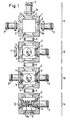
- the four components of the system shown in FIG. 1 are each with a cuboid, square in plan Basic housing 1 provided.
- the basic housing 1 is in its paired side faces provided with openings 2 of the same design. Every opening 2 is on the outside of the base body 1 by a step 2a expanded.
- the base body 1 has a closed one Bottom and an open top. The open top of the Basic housing 1 is closed by a cover 34 (FIG. 2).
- Fig. 1 is a flow collector or distributor designated.
- the system is at three of the four openings 2 of the basic housing 1 a hose connection 3 is used in each case.
- everyone Hose connection 3 has a flange 3a, which in the expanded part 2a of the opening 2 fits and sealed there, for example, is glued in tightly.
- the hollow interior of the basic housing 1 forms a collection and distribution chamber.
- the fourth opening 2 of the basic housing 1 is used for coupling to the basic housing 1 of one in FIG. 1 with 12 designated two-way valve.
- the basic housing of the components labeled 11 and 12 are interposed a sealing ring 6, which in the extended Part of the corresponding openings 2 of both basic housings is inserted, joined together.
- the two-way valve 12 comes about in that in one of the openings 2, the at 90 ° to the communicating openings 2 of components 11 and 12 is oriented on the inside Sealing seat 4 is used with which a spherical Closing body 5 cooperates.
- the one opposite the sealing seat 4 Opening 2 of the basic housing 1 is through a Blind cover 7 closed.
- the two-way valve 12 On its side facing away from component 11 the two-way valve 12 in the same way with the interposition a sealing ring 6 connected to a further component 13, which is a three-way valve.
- the three-way valve 13 differs from that Two-way valve 12 only in that two sealing seats 4 in two opposite openings 2 used are and the dummy cover 7 through a further hose connection 3 is replaced.
- the closing body 5 By rotating the shaft 20 the closing body 5 is displaced between the two sealing seats 4.
- a check valve is a further component 14 with the interposition of a sealing ring 6 to the remaining one Opening 2 of the three-way valve 13 coupled.
- This Check valve comes about in that in a Sealing seat 4 opposite opening of the basic housing 1 an insert part 10 is inserted through a blind cover and one connected to it, in the interior of the base body projecting carrier 10a is formed.
- a valve closing body 8 slidably stored. Between the insert 10 and the Valve closing body 8 is supported by a compression spring 9, which acts on the valve closing body against the sealing seat 4.
- the valve closing body 8 is also under the Effect of media pressures in the interior of the basic housing 1 or in the hose connection adjoining the sealing seat 4 3. When the media pressure inside this hose connector 3 predominates, the valve closing body 8 lifted off the sealing seat 4.
- Position indicator module 18 includes a shaft portion 35 which is on its the two-way valve 12 side facing a coupling sleeve for positive connection with the connector 20a and on its opposite side one from the Position indicator module 18 protruding connector 35a has, which corresponds to the connector 20a.
- the Position indicator module 18 includes one or more limit switches 19; additionally or alternatively, he can use be equipped with a potentiometer.
- a further assembly can be placed on the position indicator module 18 16 are placed, which is a motor drive module is.
- This module also contains one Shaft section 36 with a coupling sleeve on one and a connector 36a at its other end.
- a drive motor 17 connected to the shaft section 36 via a gear.
- a manual drive module 15 placed on the motor drive module 16 as another assembly.
- This consists essentially of a lid, one in it rotatably mounted shaft section 39, which by means of a Coupling sleeve with connector 36a of module 16 is positively connectable, and a handwheel 40 on the other End of shaft section 39.
- the shaft sections 35, 36 and 39 coaxial with each other and be positively connected to the shaft 20 by the Assemblies can be easily placed Every module 15, 16, 18 is used as needed; for example the manual drive module 15 can also directly on the Cover 34 are placed.
- a further sealing seat 4th is used instead of a two-way valve Three-way valve, such as the component designated by 13 in FIG.
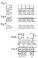
- FIGS. 3 to 7 show for the sake of example the various possible combinations within the modular valve and manifold system.
- FIG 3 a single valve 12 (or 13) with a position indicator module 18, a motor drive module 16 and another module in which it is a manual drive module 15 or one electronic control module can act.
- a single valve 12 or 13 with a position indicator module 18, a motor drive module 16 and another module in which it is a manual drive module 15 or one electronic control module can act.
- Figure 3 shows an arrangement of four of these valves in a row Condition shown.
- FIG. 4 only shows a single valve 12 (or 13) with a manual drive module 15; next to it are four these valves 12 shown lined up.
- Figure 5 is a distribution module 11 and next to it Arrangement of four strung components of this Type shown.
- Figure 6 shows the sequence of components of different types, namely a two-way valve 12 with one Position indicator module 18, motor drive module 16 and a control module 15a, further a distributor 11, another Valve 12, 13 with manual drive module 15 and finally a valve 12 or 13 that is connected to any module 50 is combined.
Landscapes
- Engineering & Computer Science (AREA)
- General Engineering & Computer Science (AREA)
- Mechanical Engineering (AREA)
- Multiple-Way Valves (AREA)
- Valve Housings (AREA)
- Filtering Of Dispersed Particles In Gases (AREA)
Claims (7)
- Système modulaire de valve et de distribution pour des milieux fluides, constitué de plusieurs composants (11, 12, 13, 14) pouvant être assemblés les uns aux autres, dans lequel tous les composants (11, 12, 13, 14) présentent un boítier de base (1) identique en forme de parallélépipède qui, sur des surfaces latérales opposées par paires, est pourvu d'ouvertures (2) de même configuration, et dans le cas de deux boítiers de base (1) assemblés l'un à l'autre, leurs espaces intérieurs sont en liaison l'un avec l'autre par des ouvertures (2) correspondantes dans les surfaces latérales, les ouvertures (2) ménagées dans les surfaces latérales peuvent, en cas de besoin, être fermées par un couvercle d'obturation (7) ou être utilisées en tant qu'ouverture de raccordement, et le boítier de base (1) peut être équipé, en cas de besoin, de parties fonctionnelles (4, 5, 8) des composants, un support (10a) faisant saillie dans l'espace intérieure du boítier de base (1) étant fixé sur une pièce d'insert (10) montée dans une ouverture (2) pour une partie fonctionnelle (8) du composant (14) concerné, caractérisé en ce que sur le support (10a), un corps de fermeture à soupape (8) commandé par ressort est monté de manière à pouvoir être déplacé le long de l'axe commun à deux ouvertures (2) opposées des surfaces latérales du boítier de base (1) et le corps de fermeture de soupape (8) coopère avec un siège d'étanchéité inséré dans l'ouverture (2) opposée.
- Système selon la revendication 1, caractérisé en ce que le boítier de base (1) présente une projection horizontale quadratique et plusieurs boítiers de base (1) peuvent se succéder dans deux directions perpendiculaires l'une par rapport à l'autre.
- Système selon l'une des revendications précédentes, caractérisé en ce que le boítier de base (1) présentant un fond fermé et une surface supérieure ouverte qui peut être fermée par un couvercle (34).
- Système selon la revendication 3, caractérisé en ce que dans une ouverture de passage du couvercle (34), un arbre (20) étant monté de manière pivotante en faisant saillie dans l'espace intérieur du boítier de base (1) et portant une partie fonctionnelle (5) des composants concernés, et en ce que l'arbre (20) fait saillie avec une pièce de raccordement (20a) hors du couvercle (34) vers l'extérieur,
- Système selon la revendication 4, caractérisé en ce qu'on peut placer sur le couvercle (34), en cas de besoin et par une liaison par coopération de formes ou de forces avec la pièce de raccordement (20a) :un module d'affichage de position (18),un module d'entraínement par moteur (16),un module d'entraínement manuel (15),un module de commande (15a) ;
chacun des modules présentant un tronçon d'arbre (35, 36, 39) pivotant, et tous les modules (18, 16, 15) pouvant aussi être reliés les uns aux autres par coopération de formes ou de forces, par l'enfichage coaxial de leurs tronçons d'arbre. - Système selon la revendication 4 ou 5, caractérisé en ce que la partie fonctionnelle des composants (12, 13) est un corps de fermeture (5) de forme sphérique qui est monté sur un bras de manivelle (32) relié à l'arbre (20) et qui coopère avec au moins un siège d'étanchéité (4) inséré dans une des ouvertures (2) des surfaces latérales.
- Système selon l'une quelconque des revendications précédentes, caractérisé en ce que les ouvertures (2) sont élargies du côté extérieur du boítier de base (1) pour recevoir une bague d'étanchéité (6).
Applications Claiming Priority (3)
| Application Number | Priority Date | Filing Date | Title |
|---|---|---|---|
| DE9402093U | 1994-02-08 | ||
| DE9402093U DE9402093U1 (de) | 1994-02-08 | 1994-02-08 | Modulares Ventil- und Verteilersystem für strömende Medien |
| EP95101412A EP0667472B1 (fr) | 1994-02-08 | 1995-02-02 | Soupape et système d'alimentation modulaires pour fluides |
Related Parent Applications (1)
| Application Number | Title | Priority Date | Filing Date |
|---|---|---|---|
| EP95101412A Division EP0667472B1 (fr) | 1994-02-08 | 1995-02-02 | Soupape et système d'alimentation modulaires pour fluides |
Publications (3)
| Publication Number | Publication Date |
|---|---|
| EP1069356A2 EP1069356A2 (fr) | 2001-01-17 |
| EP1069356A3 EP1069356A3 (fr) | 2001-10-04 |
| EP1069356B1 true EP1069356B1 (fr) | 2003-08-06 |
Family
ID=6904316
Family Applications (2)
| Application Number | Title | Priority Date | Filing Date |
|---|---|---|---|
| EP00122375A Expired - Lifetime EP1069356B1 (fr) | 1994-02-08 | 1995-02-02 | Soupape et système d'alimentation modulaires pour fluides |
| EP95101412A Expired - Lifetime EP0667472B1 (fr) | 1994-02-08 | 1995-02-02 | Soupape et système d'alimentation modulaires pour fluides |
Family Applications After (1)
| Application Number | Title | Priority Date | Filing Date |
|---|---|---|---|
| EP95101412A Expired - Lifetime EP0667472B1 (fr) | 1994-02-08 | 1995-02-02 | Soupape et système d'alimentation modulaires pour fluides |
Country Status (2)
| Country | Link |
|---|---|
| EP (2) | EP1069356B1 (fr) |
| DE (3) | DE9402093U1 (fr) |
Families Citing this family (16)
| Publication number | Priority date | Publication date | Assignee | Title |
|---|---|---|---|---|
| DE29703788U1 (de) * | 1997-03-03 | 1997-06-26 | Bürkert Werke GmbH & Co., 74653 Ingelfingen | Modularer Steuerblock für die Analysentechnik |
| DE10163785A1 (de) * | 2001-12-22 | 2003-07-03 | Mueller A & K Gmbh Co Kg | Einrichtung zum Zusammenschalten mehrerer hydraulischer oder pneumatischer Komponenten, insbesondere mehrerer Elektromagnetventile |
| DE10339096A1 (de) * | 2003-08-22 | 2005-03-10 | Grohe Water Tech Ag & Co Kg | Modulares Ventil- und Verteilersystem |
| US7261121B2 (en) * | 2005-03-29 | 2007-08-28 | Norgren, Inc. | Expandable gas or fluid distribution system |
| US20060225798A1 (en) * | 2005-03-29 | 2006-10-12 | Robert Bordonaro | Integrated expandable gas or fluid distribution system |
| JP4224862B2 (ja) | 2006-10-12 | 2009-02-18 | Smc株式会社 | バルブ装置 |
| DE202012004384U1 (de) * | 2012-05-07 | 2012-05-30 | Bürkert Werke GmbH | Modulares Ventilsystem |
| DE102015009902A1 (de) * | 2015-07-29 | 2017-02-02 | Hydac Accessories Gmbh | Verteilvorrichtung |
| WO2017063707A1 (fr) * | 2015-10-15 | 2017-04-20 | Festo Ag & Co. Kg | Dispositif formant soupape |
| DE102015221166A1 (de) * | 2015-10-29 | 2017-05-04 | Mahle International Gmbh | Fluidsystem mit Verbindungsbauteil |
| DE102016206784B3 (de) * | 2016-04-21 | 2017-10-26 | Festo Ag & Co. Kg | Fluidverteilervorrichtung |
| EP3565991A1 (fr) * | 2017-01-06 | 2019-11-13 | Hebmüller SRS Technik GmbH | Ensemble soupape |
| CN107524832B (zh) * | 2017-09-29 | 2024-05-07 | 广东汉特科技有限公司 | 一种恒温混水龙头 |
| DE202020102039U1 (de) | 2020-04-14 | 2021-07-15 | Neoperl Gmbh | Sanitär-Baukasten und sanitäre Funktionsanordnung |
| DE102020110196A1 (de) | 2020-04-14 | 2021-10-14 | Neoperl Gmbh | Sanitär-Baukasten, sanitäre Funktionsanordnung und Verfahren zur Herstellung einer sanitären Funktionsanordnung |
| DE102023117127A1 (de) * | 2023-06-29 | 2025-01-02 | Helmut Bälz GmbH | Antriebsbaukasten mit Armaturenantriebsmodulen zum Aufbauen eines Armaturenantriebssystems |
Family Cites Families (14)
| Publication number | Priority date | Publication date | Assignee | Title |
|---|---|---|---|---|
| DE7315984U (de) * | 1974-10-31 | Bosch R Gmbh | Anschlußplatte | |
| US2812154A (en) * | 1953-01-22 | 1957-11-05 | Nordstrand Sven Gosta | Valve |
| US2834368A (en) * | 1955-08-01 | 1958-05-13 | Landon R Gray | Multiple valve assembly |
| DE1650241A1 (de) * | 1967-11-02 | 1970-10-29 | Orsta Hydraulik Veb K | Verkettungseinrichtung fuer hydraulische oder pneumatische Steuer- und Regelgeraete |
| US3605805A (en) * | 1969-10-24 | 1971-09-20 | Allis Chalmers Mfg Co | Stackable rotary valves |
| US3754565A (en) * | 1971-02-23 | 1973-08-28 | D Gennetten | Anti-theft or use device for self propelled or stationary engines |
| FR2257846B1 (fr) * | 1973-07-03 | 1976-05-28 | Legris France Sa | |
| SE7604644L (sv) * | 1975-05-15 | 1976-11-16 | Fritz Stumpmeier | Apparatberare for bildande av ett seriesystem for hydroventiler |
| US4281683A (en) * | 1978-12-11 | 1981-08-04 | Poly-Glas Systems | Modular multiple-fluid component selection and delivery system |
| DE2942900C2 (de) * | 1979-10-24 | 1984-05-03 | Otto Tuchenhagen GmbH & Co KG, 2059 Büchen | Hochdruck-Fernschaltventil |
| GB2138110A (en) * | 1983-04-13 | 1984-10-17 | Drallim Ind | Improvement in and relating to control valves |
| US4934411A (en) * | 1984-08-06 | 1990-06-19 | Albrecht David E | Insert means for fluid flow system |
| FR2628501B1 (fr) * | 1988-03-09 | 1990-05-18 | Eferel Sa | Procede pour la realisation d'un dispositif d'obturation a obturateurs multiples et a circuits d'interconnexion integres adaptables selon les fonctionnalites desirees par l'utilisateur et dispositifs d'obturation realises conformement audit procede. |
| DE4205153C1 (en) * | 1992-02-20 | 1993-06-24 | Jakob 8203 Oberaudorf De Loferer | Gas couplings for multiple array of hot gas jets - has close spaced jets coupled to supply lines by short pipes held in place axially by adjustable lengths |
-
1994
- 1994-02-08 DE DE9402093U patent/DE9402093U1/de not_active Expired - Lifetime
-
1995
- 1995-02-02 DE DE59510760T patent/DE59510760D1/de not_active Expired - Lifetime
- 1995-02-02 EP EP00122375A patent/EP1069356B1/fr not_active Expired - Lifetime
- 1995-02-02 DE DE59509649T patent/DE59509649D1/de not_active Expired - Lifetime
- 1995-02-02 EP EP95101412A patent/EP0667472B1/fr not_active Expired - Lifetime
Also Published As
| Publication number | Publication date |
|---|---|
| DE9402093U1 (de) | 1994-03-31 |
| EP0667472B1 (fr) | 2001-10-04 |
| EP1069356A2 (fr) | 2001-01-17 |
| DE59509649D1 (de) | 2001-11-08 |
| EP1069356A3 (fr) | 2001-10-04 |
| EP0667472A2 (fr) | 1995-08-16 |
| EP0667472A3 (fr) | 1998-01-07 |
| DE59510760D1 (de) | 2003-09-11 |
Similar Documents
| Publication | Publication Date | Title |
|---|---|---|
| EP1069356B1 (fr) | Soupape et système d'alimentation modulaires pour fluides | |
| DE112016005328B4 (de) | Schaltventil | |
| DE60128717T2 (de) | Vierwegeventil | |
| DE102010037148A1 (de) | Mehrwegeventil und Fluidkreislauf mit einem solchen | |
| DE102014107086A1 (de) | Elektrisch betätigte Ventilanordnung | |
| DE102008011858A1 (de) | Vorrichtung zur Dämpfung einer Drehbewegung | |
| EP0402559A2 (fr) | Vanne de distribution | |
| DE102009017861A1 (de) | Ventileinrichtung | |
| DE2631764A1 (de) | Sechsweg-umschaltventil fuer fluessigkeitsdurchstroemte rohrleitungen | |
| DE1550177B1 (de) | Kegelhahn mit im Kueken mit Spiel angeordneten Dichtungsplatten | |
| EP1319144B1 (fr) | Cartouche pour robinetterie sanitaire | |
| EP0399095A2 (fr) | Robinet à tournant sphérique | |
| DE102021113817A1 (de) | Kugelventil mit mehrwinkliger dichtung für kühlmittelregler | |
| DE102007035969A1 (de) | Ventilbaukasten mit Keramikventil | |
| DE69817193T2 (de) | Membranventil und gehäuse eines membranventils | |
| EP0335090B1 (fr) | Organe de commande pour le réglage de débits | |
| DE102007007111A1 (de) | Klappenventil | |
| WO2014095403A1 (fr) | Soupape | |
| DE19546281A1 (de) | Hydraulische Lenkeinrichtung | |
| WO1991000462A1 (fr) | Dispositif de distribution | |
| DE4318926C2 (de) | Mehrwegeventil | |
| DE102020101617A1 (de) | Mehrwegventil für Fluid für eine Gerätezubereitungsvorrichtung, Mehrfluid-Mehrwegventil für eine Gerätezubereitungsvorrichtung und Gerätezubereitungsvorrichtung, insbesondere Kaffeemaschine | |
| DE102013208153A1 (de) | Stellkörper zur Leitung von Fluidströmen | |
| DE102008006450A1 (de) | Mehrwegeventil für einen Flüssigkeitskreislauf | |
| DE10012066A1 (de) | Mehrwegeventil (Pilotventilbehälter) |
Legal Events
| Date | Code | Title | Description |
|---|---|---|---|
| PUAI | Public reference made under article 153(3) epc to a published international application that has entered the european phase |
Free format text: ORIGINAL CODE: 0009012 |
|
| AC | Divisional application: reference to earlier application |
Ref document number: 667472 Country of ref document: EP |
|
| AK | Designated contracting states |
Kind code of ref document: A2 Designated state(s): DE FR GB |
|
| RIN1 | Information on inventor provided before grant (corrected) |
Inventor name: TOEPFER, HEINZ, PROF. DR. Inventor name: BARTHEL, KLAUS Inventor name: SCHREPEL, DIETER, DR. Inventor name: MUELLER, BERNHARD Inventor name: DETTMANN, HEINRICH Inventor name: PIELOTH, MANFRED |
|
| PUAL | Search report despatched |
Free format text: ORIGINAL CODE: 0009013 |
|
| AK | Designated contracting states |
Kind code of ref document: A3 Designated state(s): DE FR GB |
|
| 17P | Request for examination filed |
Effective date: 20020108 |
|
| AKX | Designation fees paid |
Free format text: DE FR GB |
|
| 17Q | First examination report despatched |
Effective date: 20020621 |
|
| GRAH | Despatch of communication of intention to grant a patent |
Free format text: ORIGINAL CODE: EPIDOS IGRA |
|
| GRAH | Despatch of communication of intention to grant a patent |
Free format text: ORIGINAL CODE: EPIDOS IGRA |
|
| GRAA | (expected) grant |
Free format text: ORIGINAL CODE: 0009210 |
|
| AC | Divisional application: reference to earlier application |
Ref document number: 0667472 Country of ref document: EP Kind code of ref document: P |
|
| AK | Designated contracting states |
Designated state(s): DE FR GB |
|
| REG | Reference to a national code |
Ref country code: GB Ref legal event code: FG4D Free format text: NOT ENGLISH |
|
| REF | Corresponds to: |
Ref document number: 59510760 Country of ref document: DE Date of ref document: 20030911 Kind code of ref document: P |
|
| GBT | Gb: translation of ep patent filed (gb section 77(6)(a)/1977) |
Effective date: 20031007 |
|
| ET | Fr: translation filed | ||
| PLBE | No opposition filed within time limit |
Free format text: ORIGINAL CODE: 0009261 |
|
| STAA | Information on the status of an ep patent application or granted ep patent |
Free format text: STATUS: NO OPPOSITION FILED WITHIN TIME LIMIT |
|
| 26N | No opposition filed |
Effective date: 20040507 |
|
| PGFP | Annual fee paid to national office [announced via postgrant information from national office to epo] |
Ref country code: FR Payment date: 20060220 Year of fee payment: 12 |
|
| GBPC | Gb: european patent ceased through non-payment of renewal fee |
Effective date: 20070202 |
|
| REG | Reference to a national code |
Ref country code: FR Ref legal event code: ST Effective date: 20071030 |
|
| PG25 | Lapsed in a contracting state [announced via postgrant information from national office to epo] |
Ref country code: GB Free format text: LAPSE BECAUSE OF NON-PAYMENT OF DUE FEES Effective date: 20070202 Ref country code: FR Free format text: LAPSE BECAUSE OF NON-PAYMENT OF DUE FEES Effective date: 20070228 |
|
| PGFP | Annual fee paid to national office [announced via postgrant information from national office to epo] |
Ref country code: GB Payment date: 20060201 Year of fee payment: 12 |
|
| PGFP | Annual fee paid to national office [announced via postgrant information from national office to epo] |
Ref country code: DE Payment date: 20130227 Year of fee payment: 19 |
|
| REG | Reference to a national code |
Ref country code: DE Ref legal event code: R119 Ref document number: 59510760 Country of ref document: DE |
|
| REG | Reference to a national code |
Ref country code: DE Ref legal event code: R119 Ref document number: 59510760 Country of ref document: DE Effective date: 20140902 |
|
| PG25 | Lapsed in a contracting state [announced via postgrant information from national office to epo] |
Ref country code: DE Free format text: LAPSE BECAUSE OF NON-PAYMENT OF DUE FEES Effective date: 20140902 |