EP1069356B1 - Modular valve and delivery system for fluids - Google Patents
Modular valve and delivery system for fluids Download PDFInfo
- Publication number
- EP1069356B1 EP1069356B1 EP00122375A EP00122375A EP1069356B1 EP 1069356 B1 EP1069356 B1 EP 1069356B1 EP 00122375 A EP00122375 A EP 00122375A EP 00122375 A EP00122375 A EP 00122375A EP 1069356 B1 EP1069356 B1 EP 1069356B1
- Authority
- EP
- European Patent Office
- Prior art keywords
- openings
- basic housing
- shaft
- basic
- cover
- Prior art date
- Legal status (The legal status is an assumption and is not a legal conclusion. Google has not performed a legal analysis and makes no representation as to the accuracy of the status listed.)
- Expired - Lifetime
Links
Images

Classifications
-
- F—MECHANICAL ENGINEERING; LIGHTING; HEATING; WEAPONS; BLASTING
- F16—ENGINEERING ELEMENTS AND UNITS; GENERAL MEASURES FOR PRODUCING AND MAINTAINING EFFECTIVE FUNCTIONING OF MACHINES OR INSTALLATIONS; THERMAL INSULATION IN GENERAL
- F16K—VALVES; TAPS; COCKS; ACTUATING-FLOATS; DEVICES FOR VENTING OR AERATING
- F16K27/00—Construction of housing; Use of materials therefor
- F16K27/003—Housing formed from a plurality of the same valve elements
-
- F—MECHANICAL ENGINEERING; LIGHTING; HEATING; WEAPONS; BLASTING
- F16—ENGINEERING ELEMENTS AND UNITS; GENERAL MEASURES FOR PRODUCING AND MAINTAINING EFFECTIVE FUNCTIONING OF MACHINES OR INSTALLATIONS; THERMAL INSULATION IN GENERAL
- F16L—PIPES; JOINTS OR FITTINGS FOR PIPES; SUPPORTS FOR PIPES, CABLES OR PROTECTIVE TUBING; MEANS FOR THERMAL INSULATION IN GENERAL
- F16L39/00—Joints or fittings for double-walled or multi-channel pipes or pipe assemblies
Definitions
- the invention relates to a modular valve and manifold system for flowing media according to the generic term of Claim 1.
- a system is for example from the US-A-2 834 368.
- valve groups It is already for the compact construction of valve groups known, individual valves on a common mounting plate to attach, in which also the medium through channels and bores to and from the valves becomes. Furthermore, it is known for the individual valves with housings to be equipped, which are lined up directly can. But there is a need for a modular one Valve and manifold system with a few elementary Basic and functional parts a wide range of functions covers, especially collecting, switching, distributing, Regulation and reversal of fluid flows. A special Areas of application for such a system are climate and Heating equipment.
- the modular valve and manifold system according to the invention for flowing media fulfills this need.
- the invention is a modular valve and manifold system with the characteristic features of claim 1 provided.
- the cuboid basic housing can be lined up in two perpendicular directions become. Every component of the system is through Equipping the basic housing with the required functional parts provided. With a limited scope of Functional parts can all essential collection, Switching, distribution, control and reversal tasks are fulfilled.
- the main functional parts are sealing seats, into the openings in the side faces of the basic housing can be used, and closing body into consideration with interact with these sealing seats. This way you can add Check valves also two-way valves with variable throttling of the flow rate or, in the case of spherical formation of the closing body, three-way valves are realized, which distribute the medium on two outputs.
- the body has a closed bottom and an open one Top, which can be closed by a lid. in the simplest case of a flow distributor or check valve the lid is closed. If functional elements must be actuated inside the basic housing, is preferably in a through opening of the Cover a shaft rotatably mounted in the interior of the base body protrudes and a functional part of the concerned Component of the system carries. The wave protrudes with a connector out of the lid. You can now use the cover for the respective function required assemblies of the component, for example a position indicator module, a motor drive module and / or a manual drive module.
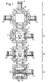
- the four components of the system shown in FIG. 1 are each with a cuboid, square in plan Basic housing 1 provided.
- the basic housing 1 is in its paired side faces provided with openings 2 of the same design. Every opening 2 is on the outside of the base body 1 by a step 2a expanded.
- the base body 1 has a closed one Bottom and an open top. The open top of the Basic housing 1 is closed by a cover 34 (FIG. 2).
- Fig. 1 is a flow collector or distributor designated.
- the system is at three of the four openings 2 of the basic housing 1 a hose connection 3 is used in each case.
- everyone Hose connection 3 has a flange 3a, which in the expanded part 2a of the opening 2 fits and sealed there, for example, is glued in tightly.
- the hollow interior of the basic housing 1 forms a collection and distribution chamber.
- the fourth opening 2 of the basic housing 1 is used for coupling to the basic housing 1 of one in FIG. 1 with 12 designated two-way valve.
- the basic housing of the components labeled 11 and 12 are interposed a sealing ring 6, which in the extended Part of the corresponding openings 2 of both basic housings is inserted, joined together.
- the two-way valve 12 comes about in that in one of the openings 2, the at 90 ° to the communicating openings 2 of components 11 and 12 is oriented on the inside Sealing seat 4 is used with which a spherical Closing body 5 cooperates.
- the one opposite the sealing seat 4 Opening 2 of the basic housing 1 is through a Blind cover 7 closed.
- the two-way valve 12 On its side facing away from component 11 the two-way valve 12 in the same way with the interposition a sealing ring 6 connected to a further component 13, which is a three-way valve.
- the three-way valve 13 differs from that Two-way valve 12 only in that two sealing seats 4 in two opposite openings 2 used are and the dummy cover 7 through a further hose connection 3 is replaced.
- the closing body 5 By rotating the shaft 20 the closing body 5 is displaced between the two sealing seats 4.
- a check valve is a further component 14 with the interposition of a sealing ring 6 to the remaining one Opening 2 of the three-way valve 13 coupled.
- This Check valve comes about in that in a Sealing seat 4 opposite opening of the basic housing 1 an insert part 10 is inserted through a blind cover and one connected to it, in the interior of the base body projecting carrier 10a is formed.
- a valve closing body 8 slidably stored. Between the insert 10 and the Valve closing body 8 is supported by a compression spring 9, which acts on the valve closing body against the sealing seat 4.
- the valve closing body 8 is also under the Effect of media pressures in the interior of the basic housing 1 or in the hose connection adjoining the sealing seat 4 3. When the media pressure inside this hose connector 3 predominates, the valve closing body 8 lifted off the sealing seat 4.
- Position indicator module 18 includes a shaft portion 35 which is on its the two-way valve 12 side facing a coupling sleeve for positive connection with the connector 20a and on its opposite side one from the Position indicator module 18 protruding connector 35a has, which corresponds to the connector 20a.
- the Position indicator module 18 includes one or more limit switches 19; additionally or alternatively, he can use be equipped with a potentiometer.
- a further assembly can be placed on the position indicator module 18 16 are placed, which is a motor drive module is.
- This module also contains one Shaft section 36 with a coupling sleeve on one and a connector 36a at its other end.
- a drive motor 17 connected to the shaft section 36 via a gear.
- a manual drive module 15 placed on the motor drive module 16 as another assembly.
- This consists essentially of a lid, one in it rotatably mounted shaft section 39, which by means of a Coupling sleeve with connector 36a of module 16 is positively connectable, and a handwheel 40 on the other End of shaft section 39.
- the shaft sections 35, 36 and 39 coaxial with each other and be positively connected to the shaft 20 by the Assemblies can be easily placed Every module 15, 16, 18 is used as needed; for example the manual drive module 15 can also directly on the Cover 34 are placed.
- a further sealing seat 4th is used instead of a two-way valve Three-way valve, such as the component designated by 13 in FIG.
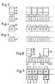
- FIGS. 3 to 7 show for the sake of example the various possible combinations within the modular valve and manifold system.
- FIG 3 a single valve 12 (or 13) with a position indicator module 18, a motor drive module 16 and another module in which it is a manual drive module 15 or one electronic control module can act.
- a single valve 12 or 13 with a position indicator module 18, a motor drive module 16 and another module in which it is a manual drive module 15 or one electronic control module can act.
- Figure 3 shows an arrangement of four of these valves in a row Condition shown.
- FIG. 4 only shows a single valve 12 (or 13) with a manual drive module 15; next to it are four these valves 12 shown lined up.
- Figure 5 is a distribution module 11 and next to it Arrangement of four strung components of this Type shown.
- Figure 6 shows the sequence of components of different types, namely a two-way valve 12 with one Position indicator module 18, motor drive module 16 and a control module 15a, further a distributor 11, another Valve 12, 13 with manual drive module 15 and finally a valve 12 or 13 that is connected to any module 50 is combined.
Landscapes
- Engineering & Computer Science (AREA)
- General Engineering & Computer Science (AREA)
- Mechanical Engineering (AREA)
- Multiple-Way Valves (AREA)
- Valve Housings (AREA)
- Filtering Of Dispersed Particles In Gases (AREA)
Description
Die Erfindung betrifft ein modulares Ventil- und Verteilersystem für strömende Medien gemäß dem Oberbegriff des Anspruchs 1. Ein solches System ist beispielsweise aus der US-A-2 834 368 bekannt.The invention relates to a modular valve and manifold system for flowing media according to the generic term of Claim 1. Such a system is for example from the US-A-2 834 368.
Zum kompakten Aufbau von Ventilgruppen ist es bereits bekannt, einzelne Ventile auf einer gemeinsamen Montageplatte zu befestigen, in der auch das Medium durch Kanäle und Bohrungen zu den Ventilen und von diesen fort geführt wird. Ferner ist es bekannt, die einzelnen Ventile mit Gehäusen auszustatten, die direkt aneinandergereiht werden können. Es besteht aber ein Bedarf nach einem modularen Ventil- und Verteilersystem, das mit wenigen elementaren Grund- und Funktionsteilen ein breites Spektrum von Funktionen abdeckt, insbesondere das Sammeln, Schalten, Verteilen, Regeln und Umsteuern von Fluidströmen. Ein besonderes Anwendungsgebiet für ein solches System sind Klima- und Heizanlagen. It is already for the compact construction of valve groups known, individual valves on a common mounting plate to attach, in which also the medium through channels and bores to and from the valves becomes. Furthermore, it is known for the individual valves with housings to be equipped, which are lined up directly can. But there is a need for a modular one Valve and manifold system with a few elementary Basic and functional parts a wide range of functions covers, especially collecting, switching, distributing, Regulation and reversal of fluid flows. A special Areas of application for such a system are climate and Heating equipment.
Das erfindungsgemäße modulare Ventil- und Verteilersystem für strömende Medien erfüllt dieses Bedürfnis. Gemäß der Erfindung ist ein modulares Ventil- und Verteilersystem mit den kennzeichnenden Merkmalen des Anspruchs 1 vorgesehen.The modular valve and manifold system according to the invention for flowing media fulfills this need. According to The invention is a modular valve and manifold system with the characteristic features of claim 1 provided.
Auf diese Weise wird ein Rückschlagventil bereitgestellt.In this way, a check valve is provided.
Die quaderförmigen Grundgehäuse können in zwei aufeinander senkrechten Richtungen aneinandergereiht werden. Jede Komponente des Systems wird durch Ausrüsten des Grundgehäuses mit den benötigten Funktionsteilen bereitgestellt. Mit einem begrenzten Umfang von Funktionsteilen können so alle wesentlichen Sammel-, Schalt-, Verteil-, Regel- und Umsteueraufgaben erfüllt werden.The cuboid basic housing can be lined up in two perpendicular directions become. Every component of the system is through Equipping the basic housing with the required functional parts provided. With a limited scope of Functional parts can all essential collection, Switching, distribution, control and reversal tasks are fulfilled.
Als Funktionsteile kommen in erster Linie Dichtsitze, die in die Öffnungen der Seitenflächen des Grundgehäuses einsetzbar sind, und Schließkörper in Betracht, die mit diesen Dichtsitzen zusammenwirken. Auf diese Weise können neben Rückschlagventilen auch Zweiwegeventile mit variabler Drosselung des Durchflusses oder, bei kugelförmiger Ausbildung des Schließkörpers, Dreiwegeventile verwirklicht werden, die das Medium auf zwei Ausgänge verteilen.The main functional parts are sealing seats, into the openings in the side faces of the basic housing can be used, and closing body into consideration with interact with these sealing seats. This way you can add Check valves also two-way valves with variable throttling of the flow rate or, in the case of spherical formation of the closing body, three-way valves are realized, which distribute the medium on two outputs.
Bei einer bevorzugten Ausführungsform des Systems hat der Grundkörper einen geschlossenen Boden und eine offene Oberseite, die durch einen Deckel verschließbar ist. Im einfachsten Falle eines Strömungsverteilers oder Rückschlagventils ist der Deckel geschlossen. Wenn Funktionselemente im Inneren des Grundgehäuses betätigt werden müssen, ist vorzugsweise in einer Durchgangsöffnung des Deckels eine Welle drehbar gelagert, die in den Innenraum des Grundkörpers hineinragt und ein Funktionsteil der betreffenden Komponente des Systems trägt. Die Welle ragt mit einem Anschlußstück aus dem Deckel nach außen heraus. Auf dem Deckel können nun die für die jeweilige Funktion der Komponente benötigten Baugruppen aufgesetzt werden, beispielsweise ein Stellungsmeldermodul, ein Motor-Antriebsmodul und/oder ein Handantriebsmodul. In a preferred embodiment of the system the body has a closed bottom and an open one Top, which can be closed by a lid. in the simplest case of a flow distributor or check valve the lid is closed. If functional elements must be actuated inside the basic housing, is preferably in a through opening of the Cover a shaft rotatably mounted in the interior of the base body protrudes and a functional part of the concerned Component of the system carries. The wave protrudes with a connector out of the lid. You can now use the cover for the respective function required assemblies of the component, for example a position indicator module, a motor drive module and / or a manual drive module.
Weitere Merkmale und Vorteile der Erfindung ergeben
sich aus der folgenden Beschreibung mehrerer Ausführungsformen
und aus der Zeichnung, auf die Bezug genommen wird.
In der Zeichnung zeigen:
Die in Fig. 1 gezeigten vier Komponenten des Systems
sind jeweils mit einem quaderförmigen, im Grundriß quadratischen
Grundgehäuse 1 versehen. Das Grundgehäuse 1 ist in
seinen paarweise einander gegenüberliegenden Seitenflächen
mit gleichgestalteten Öffnungen 2 versehen. Jede Öffnung 2
ist an der Außenseite des Grundkörpers 1 durch eine Stufe
2a erweitert. Der Grundkörper 1 besitzt einen geschlossenen
Boden und eine offene Oberseite. Die offene Oberseite des
Grundgehäuses 1 wird durch einen Deckel 34 (Fig. 2) verschlossen.The four components of the system shown in FIG. 1
are each with a cuboid, square in plan
Basic housing 1 provided. The basic housing 1 is in
its paired side faces
provided with openings 2 of the same design. Every opening 2
is on the outside of the base body 1 by a
Mit 11 ist in Fig. 1 ein Strömungssammler oder -verteiler
bezeichnet. Bei dieser Ausführung einer Komponente
des Systems wird an drei der vier Öffnungen 2 des Grundgehäuses
1 jeweils ein Schlauchanschluß 3 eingesetzt. Jeder
Schlauchanschluß 3 besitzt einen Flansch 3a, der in den
erweiterten Teil 2a der Öffnung 2 paßt und dort abgedichtet,
beispielsweise dicht eingeklebt, ist. Der hohle Innenraum
des Grundgehäuses 1 bildet eine Sammel- und Verteilerkammer.
Die vierte Öffnung 2 des Grundgehäuses 1
dient zur Kopplung mit dem Grundgehäuse 1 eines in Figur 1
mit 12 bezeichneten Zweiwegeventils. Die Grundgehäuse der
mit 11 und 12 bezeichneten Komponenten werden unter Zwischenfügung
eines Dichtrings 6, der in den erweiterten
Teil der korrespondierenden Öffnungen 2 beider Grundgehäuse
eingesetzt ist, aneinandergefügt. Das Zweiwegeventil 12
kommt dadurch zustande, daß in eine der Öffnungen 2, die
unter 90° zu den miteinander kommunizierenden Öffnungen 2
der Komponenten 11 und 12 orientiert ist, innenseitig ein
Dichtsitz 4 eingesetzt ist, mit dem ein kugelförmiger
Schließkörper 5 zusammenwirkt. Der kugelförmige Schließkörper
5 ist, wie aus Figur 2 ersichtlich, mittels eines
Lagerzapfens 30 drehbar an einem Kurbelarm 32 gelagert,
der an eine drehbar im Deckel 34 gelagerte Welle 20 angeschlossen
ist. Durch Drehung der Welle 20 wird der
Schließkörper 5 gegen den Dichtsitz 4 und von diesem fort
bewegt, um den Durchfluß zu dem in die betreffende Öffnung
eingesetzten Schlauchanschluß 3 mehr oder weniger stark zu
drosseln bzw. abzusperren. Die dem Dichtsitz 4 gegenüberliegende
Öffnung 2 des Grundgehäuses 1 ist durch einen
Blinddeckel 7 verschlossen.With 11 in Fig. 1 is a flow collector or distributor
designated. In this execution of a component
the system is at three of the four openings 2 of the basic housing
1 a hose connection 3 is used in each case. Everyone
Hose connection 3 has a
Auf seiner von der Komponente 11 abgewandten Seite ist
das Zweiwegeventil 12 in gleicher Weise unter Zwischenfügung
eines Dichtrings 6 an eine weitere Komponente 13 angeschlossen,
bei der es sich um ein Dreiwegeventil handelt.
Das Dreiwegeventil 13 unterscheidet sich von dem
Zweiwegeventil 12 nur dadurch, daß zwei Dichtsitze 4 in
zwei einander gegenüberliegende Öffnungen 2 eingesetzt
sind und der Blinddeckel 7 durch einen weiteren Schlauchanschluß
3 ersetzt ist. Durch Drehung der Welle 20 wird
der Schließkörper 5 zwischen den beiden Dichtsitzen 4 verlagert.On its side facing away from
Als weitere Komponente 14 ist ein Rückschlagventil
unter Zwischenfügung eines Dichtrings 6 an die verbleibende
Öffnung 2 des Dreiwegeventils 13 angekoppelt. Dieses
Rückschlagventil kommt dadurch zustande, daß in eine dem
Dichtsitz 4 gegenüberliegende Öffnung des Grundgehäuses 1
ein Einsatzteil 10 eingesetzt ist, das durch einen Blinddeckel
und einen daran angeschlossenen, in den Innenraum
des Grundkörpers ragenden Träger 10a gebildet ist. An diesem
Träger 10a ist ein Ventil-Schließkörper 8 gleitverschiebbar
gelagert. Zwischen dem Einsatzteil 10 und dem
Ventil-Schließkörper 8 ist eine Druckfeder 9 abgestützt,
die den Ventil-Schließkörper gegen den Dichtsitz 4 beaufschlagt.
Der Ventil-Schließkörper 8 steht ferner unter der
Wirkung der Mediendrücke im Innenraum des Grundgehäuses 1
bzw. in dem an den Dichtsitz 4 anschließenden Schlauchanschluß
3. Wenn der Mediendruck im Inneren dieses Schlauchanschlusses
3 überwiegt, wird der Ventil-Schließkörper 8
von dem Dichtsitz 4 abgehoben.A check valve is a further component 14
with the interposition of a
Bei dem in Figur 2 gezeigten Zweiwegeventil 12 ist das
aus dem Deckel 34 nach außen herausragende Ende der Welle
20 als Vierkant-Anschlußstück 20a ausgebildet. Eine erste,
auf den Deckel 34 aufgesetzte Baugruppe ist durch einen
Stellungsmeldermodul 18 gebildet. Dieser Stellungsmeldermodul
18 etnhält einen Wellenabschnitt 35, der auf seiner
dem Zweiwegeventil 12 zugewandten Seite eine Kupplungsmuffe
zur formschlüssigen Verbindung mit dem Anschlußstück
20a und auf seiner gegenüberliegenden Seite ein aus dem
Stellungsmeldermodul 18 herausragendes Anschlußstück 35a
aufweist, das mit dem Anschlußstück 20a übereinstimmt. Der
Stellungsmeldermodul 18 enthält einen oder mehrere Endlagenschalter
19; zusätzlich oder alternativ kann er mit
einem Potentiometer ausgestattet sein.In the two-
Auf den Stellungsmeldermodul 18 kann eine weitere Baugruppe
16 aufgesetzt werden, bei der es sich um einen Motor-Antriebsmodul
handelt. Auch dieser Modul enthält einen
Wellenabschnitt 36 mit einer Kupplungsmuffe an seinem einen
und einem Anschlußstück 36a an seinem anderen Ende. Im
Inneren des Antriebsmoduls 16 ist ein Antriebsmotor 17
über ein Getriebe an den Wellenabschnitt 36 angeschlossen.A further assembly can be placed on the
Schließlich ist auf dem Motor-Antriebsmodul 16 als
weitere Baugruppe ein Handantriebsmodul 15 augesetzt. Dieser
besteht im wesentlichen aus einem Deckel, einem darin
drehbar gelagerten Wellenabschnitt 39, der mittels einer
Kupplungsmuffe mit dem Anschlußstück 36a des Moduls 16
formschlüssig verbindbar ist, und einem Handrad 40 am anderen
Ende des Wellenabschnitts 39.Finally, on the
Wie aus Figur 2 ohne weiteres ersichtlich ist, können
die Wellenabschnitte 35, 36 und 39 koaxial miteinander und
mit der Welle 20 formschlüssig verbunden werden, indem die
Baugruppen einfach aufeinandergesetzt werden. Jeder Modul
15, 16, 18 wird bedarfsweise verwendet; beispielsweise
kann der Handantriebsmodul 15 auch unmittelbar auf den
Deckel 34 aufgesetzt werden.As can easily be seen from FIG. 2,
the
Wenn anstelle des Blinddeckels 7 in die betreffende
Öffnung 2 des Grundgehäuses 1 ein weiterer Dichtsitz 4
eingesetzt wird, entsteht statt eines Zweiwegeventils ein
Dreiwegeventil, wie die in Figur 1 mit 13 bezeichnete Komponente.If instead of the
Die Skizzen der Figur 3 bis 7 zeigen beispielshalber die verschiedenen Kombinationsmöglichkeiten innerhalb des modularen Ventil- und Verteilersystems.The sketches of FIGS. 3 to 7 show for the sake of example the various possible combinations within the modular valve and manifold system.
In Figur 3 ist zunächst ein einzelnes Ventil 12 (oder
13) mit einem Stellungsmeldermodul 18, einem Motor-Antriebsmodul
16 und einem weiteren Modul gezeigt, bei dem
es sich um einen Handantriebsmodul 15 oder aber um einen
elektronischen Steuermodul handeln kann. Daneben ist in
Figur 3 eine Anordnung von vier dieser Ventile im aneinandergereihten
Zustand gezeigt.In Figure 3, a single valve 12 (or
13) with a
Figur 4 zeigt ein einzelnes Ventil 12 (oder 13) lediglich
mit einem Handantriebsmodul 15; daneben sind vier
dieser Ventile 12 aneinandergereiht dargestellt.Figure 4 only shows a single valve 12 (or 13)
with a
In Figur 5 ist ein Verteilermodul 11 und daneben eine
Anordnung von vier aneinandergereihten Komponenten dieses
Typs gezeigt. In Figure 5 is a
Figur 6 zeigt die Aneinanderreihung von Komponenten
verschiedenen Typs, nämlich ein Zweiwegeventil 12 mit einem
Stellungsmeldermodul 18, Motor-Antriebsmodul 16 und
einem Steuermodul 15a, ferner ein Verteiler 11, ein weiteres
Ventil 12, 13 mit Handantriebsmodul 15 und schließlich
ein Ventil 12 oder 13, das mit einem beliebigen Modul 50
kombiniert ist.Figure 6 shows the sequence of components
of different types, namely a two-
Wie aus Figur 7 ersichtlich ist, können die verschiedenen Komponenten in zwei zueinander senkrechten Richtungen aneinandergefügt werden, wodurch komplexe Ventil- und Verteilergruppen entstehen, zumal bei dieser zweidimensionalen Aneinanderreihung keine Einschränkungen bezüglich des Typs der darin verwendeten Komponenten bestehen.As can be seen from Figure 7, the different Components in two mutually perpendicular directions be joined together, creating complex valve and Distribution groups are created, especially with this two-dimensional one Stringing no restrictions regarding the type of components used therein.
Claims (7)
- A modular valve and distributor system for flowing media, constructed of several components (11, 12, 13, 14) which can be fitted together, in which all the components (11, 12, 13, 14) have an identical right parallelepipedal basic housing (1) which has lateral surfaces located opposite each other in pairs with identical openings (2), and in which, where any two basic housings (1) are fitted together, their interiors communicate through corresponding openings (2) in their lateral surfaces, the openings (2) in the lateral surfaces being adapted to be sealed with blind covers (7) or used as connection openings as required, and the basic housings (1) being adapted to be fitted with functional elements (4, 5, 8) of the components as required, a carrier (10a) for a functional element (8) of the respective component (14) being secured to an insertion piece (10) inserted in an opening (2), the carrier (10a) protruding into the interior of the basic housing (1), characterized in that a spring-loaded valve closing body (8) is mounted on the carrier (10a) for displacement along the common axis of two openings (2) located opposite each other in the lateral surfaces of the basic housing (1) and the valve closing body (8) cooperates with a sealing seat (4) inserted in the opposite opening (2).
- The system according to claim 1, characterized in that the basic housing (1) has a square base and that several basic housings (1) can be fitted together in two dimensions at right angles to each other.
- The system according to either of the preceding claims, characterized in that the basic housing (1) has a closed bottom and an open top which can be sealed with a cover (34).
- The system according to claim 3, characterized in that a shaft (20) is rotatably mounted in a through opening in the cover (34), the shaft (20) protruding into the interior of the basic housing (1) and carrying a functional element (5) of the respective component, and that a connection piece (20a) of the shaft (20) protrudes outwardly from the cover (34).
- The system according to claim 4, characterized in that the following items can be fitted to the cover (34) and connected to the connection piece (20a) by interlocking or force-transmitting means as required:a position-sensing module (18),a motorised-drive module (16),a manual-drive module (15),a control module (15a);
each module having a rotatable shaft section (35, 36, 39) and all modules (18, 16, 15) being adapted to be connected also to each other by interlocking or force-transmitting means by fitting their shaft sections together coaxially. - The system according to claim 4 or 5, characterized in that the functional element of the component (12, 13) is a spherical closing body (5) which is supported on a crank arm (32) connected to the shaft (20) and which cooperates with at least one sealing seat (4) inserted in one of the openings (2) in the lateral surfaces.
- The system according to any of the preceding claims, characterized in that the openings (2) on the outside of the basic housing (1) are enlarged so that a sealing washer (6) can be accommodated.
Applications Claiming Priority (3)
| Application Number | Priority Date | Filing Date | Title |
|---|---|---|---|
| DE9402093U DE9402093U1 (en) | 1994-02-08 | 1994-02-08 | Modular valve and distributor system for flowing media |
| DE9402093U | 1994-02-08 | ||
| EP95101412A EP0667472B1 (en) | 1994-02-08 | 1995-02-02 | Modular valve and delivery system for fluids |
Related Parent Applications (1)
| Application Number | Title | Priority Date | Filing Date |
|---|---|---|---|
| EP95101412A Division EP0667472B1 (en) | 1994-02-08 | 1995-02-02 | Modular valve and delivery system for fluids |
Publications (3)
| Publication Number | Publication Date |
|---|---|
| EP1069356A2 EP1069356A2 (en) | 2001-01-17 |
| EP1069356A3 EP1069356A3 (en) | 2001-10-04 |
| EP1069356B1 true EP1069356B1 (en) | 2003-08-06 |
Family
ID=6904316
Family Applications (2)
| Application Number | Title | Priority Date | Filing Date |
|---|---|---|---|
| EP95101412A Expired - Lifetime EP0667472B1 (en) | 1994-02-08 | 1995-02-02 | Modular valve and delivery system for fluids |
| EP00122375A Expired - Lifetime EP1069356B1 (en) | 1994-02-08 | 1995-02-02 | Modular valve and delivery system for fluids |
Family Applications Before (1)
| Application Number | Title | Priority Date | Filing Date |
|---|---|---|---|
| EP95101412A Expired - Lifetime EP0667472B1 (en) | 1994-02-08 | 1995-02-02 | Modular valve and delivery system for fluids |
Country Status (2)
| Country | Link |
|---|---|
| EP (2) | EP0667472B1 (en) |
| DE (3) | DE9402093U1 (en) |
Families Citing this family (16)
| Publication number | Priority date | Publication date | Assignee | Title |
|---|---|---|---|---|
| DE29703788U1 (en) | 1997-03-03 | 1997-06-26 | Bürkert Werke GmbH & Co., 74653 Ingelfingen | Modular control block for analysis technology |
| DE10163785A1 (en) * | 2001-12-22 | 2003-07-03 | Mueller A & K Gmbh Co Kg | Device for interconnecting several hydraulic or pneumatic components, in particular several solenoid valves |
| DE10339096A1 (en) * | 2003-08-22 | 2005-03-10 | Grohe Water Tech Ag & Co Kg | Modular valve and distribution system |
| US7261121B2 (en) * | 2005-03-29 | 2007-08-28 | Norgren, Inc. | Expandable gas or fluid distribution system |
| US20060225798A1 (en) * | 2005-03-29 | 2006-10-12 | Robert Bordonaro | Integrated expandable gas or fluid distribution system |
| JP4224862B2 (en) * | 2006-10-12 | 2009-02-18 | Smc株式会社 | Valve device |
| DE202012004384U1 (en) * | 2012-05-07 | 2012-05-30 | Bürkert Werke GmbH | Modular valve system |
| DE102015009902A1 (en) * | 2015-07-29 | 2017-02-02 | Hydac Accessories Gmbh | distributor |
| WO2017063707A1 (en) * | 2015-10-15 | 2017-04-20 | Festo Ag & Co. Kg | Valve device |
| DE102015221166A1 (en) * | 2015-10-29 | 2017-05-04 | Mahle International Gmbh | Fluid system with connecting component |
| DE102016206784B3 (en) * | 2016-04-21 | 2017-10-26 | Festo Ag & Co. Kg | Fluid distribution device |
| WO2018127318A1 (en) * | 2017-01-06 | 2018-07-12 | Hebmüller SRS Technik GmbH | Valve arrangement |
| CN107524832B (en) * | 2017-09-29 | 2024-05-07 | 广东汉特科技有限公司 | Constant temperature mixing tap |
| DE202020102039U1 (en) | 2020-04-14 | 2021-07-15 | Neoperl Gmbh | Sanitary construction kit and sanitary functional arrangement |
| DE102020110196A1 (en) | 2020-04-14 | 2021-10-14 | Neoperl Gmbh | Sanitary construction kit, sanitary functional arrangement and method for producing a sanitary functional arrangement |
| DE102023117127A1 (en) * | 2023-06-29 | 2025-01-02 | Helmut Bälz GmbH | Drive kit with valve drive modules for building a valve drive system |
Family Cites Families (14)
| Publication number | Priority date | Publication date | Assignee | Title |
|---|---|---|---|---|
| DE7315984U (en) * | 1974-10-31 | Bosch R Gmbh | Connection plate | |
| US2812154A (en) * | 1953-01-22 | 1957-11-05 | Nordstrand Sven Gosta | Valve |
| US2834368A (en) * | 1955-08-01 | 1958-05-13 | Landon R Gray | Multiple valve assembly |
| DE1650241A1 (en) * | 1967-11-02 | 1970-10-29 | Orsta Hydraulik Veb K | Linking device for hydraulic or pneumatic control and regulating devices |
| US3605805A (en) * | 1969-10-24 | 1971-09-20 | Allis Chalmers Mfg Co | Stackable rotary valves |
| US3754565A (en) * | 1971-02-23 | 1973-08-28 | D Gennetten | Anti-theft or use device for self propelled or stationary engines |
| FR2257846B1 (en) * | 1973-07-03 | 1976-05-28 | Legris France Sa | |
| SE7604644L (en) * | 1975-05-15 | 1976-11-16 | Fritz Stumpmeier | APPARATUS CARRIER FOR THE FORMATION OF A SERIAL SYSTEM FOR HYDROVAL VALVES |
| US4281683A (en) * | 1978-12-11 | 1981-08-04 | Poly-Glas Systems | Modular multiple-fluid component selection and delivery system |
| DE2942900C2 (en) * | 1979-10-24 | 1984-05-03 | Otto Tuchenhagen GmbH & Co KG, 2059 Büchen | High pressure remote control valve |
| GB2138110A (en) * | 1983-04-13 | 1984-10-17 | Drallim Ind | Improvement in and relating to control valves |
| US4934411A (en) * | 1984-08-06 | 1990-06-19 | Albrecht David E | Insert means for fluid flow system |
| FR2628501B1 (en) * | 1988-03-09 | 1990-05-18 | Eferel Sa | METHOD FOR THE PRODUCTION OF A SHUTTERING DEVICE WITH MULTIPLE SHUTTERS AND INTEGRATED INTERCONNECTION CIRCUITS ACCORDING TO THE FUNCTIONALITIES DESIRED BY THE USER AND SHUTTERING DEVICES REALIZED ACCORDING TO SAID PROCESS. |
| DE4205153C1 (en) * | 1992-02-20 | 1993-06-24 | Jakob 8203 Oberaudorf De Loferer | Gas couplings for multiple array of hot gas jets - has close spaced jets coupled to supply lines by short pipes held in place axially by adjustable lengths |
-
1994
- 1994-02-08 DE DE9402093U patent/DE9402093U1/en not_active Expired - Lifetime
-
1995
- 1995-02-02 DE DE59510760T patent/DE59510760D1/en not_active Expired - Lifetime
- 1995-02-02 EP EP95101412A patent/EP0667472B1/en not_active Expired - Lifetime
- 1995-02-02 DE DE59509649T patent/DE59509649D1/en not_active Expired - Lifetime
- 1995-02-02 EP EP00122375A patent/EP1069356B1/en not_active Expired - Lifetime
Also Published As
| Publication number | Publication date |
|---|---|
| EP0667472B1 (en) | 2001-10-04 |
| EP0667472A2 (en) | 1995-08-16 |
| EP0667472A3 (en) | 1998-01-07 |
| DE9402093U1 (en) | 1994-03-31 |
| EP1069356A3 (en) | 2001-10-04 |
| DE59510760D1 (en) | 2003-09-11 |
| EP1069356A2 (en) | 2001-01-17 |
| DE59509649D1 (en) | 2001-11-08 |
Similar Documents
| Publication | Publication Date | Title |
|---|---|---|
| EP1069356B1 (en) | Modular valve and delivery system for fluids | |
| DE112016005328B4 (en) | switching valve | |
| DE102010037148A1 (en) | Multi-way valve and fluid circuit with such | |
| DE714381C (en) | Control valve device | |
| DE1810552B2 (en) | Swivel joint with a horizontal swivel axis for swivel arms connected via spring compensation, in particular for medical devices | |
| EP0402559A2 (en) | Diverter-valve | |
| DE102009017861A1 (en) | valve means | |
| DE2631764A1 (en) | SIX-WAY SWITCHING VALVE FOR LIQUID THROUGH PIPES | |
| DE1550177B1 (en) | Cone valve with sealing plates arranged with play in the plug | |
| EP1319144B1 (en) | Cartridge for sanitary appliances | |
| EP0399095A2 (en) | Ball valve | |
| DE102021113817A1 (en) | BALL VALVE WITH MULTI-ANGLE SEAL FOR COOLANT REGULATOR | |
| DE102007035969A1 (en) | Ceramic valve especially for water systems has a modular construction with fixed and movable cylindrical components | |
| DE69817193T2 (en) | DIAPHRAGM VALVE AND HOUSING OF A DIAPHRAGM VALVE | |
| EP0335090B1 (en) | Control element for the adjustment of flow rate | |
| DE4317706A1 (en) | Directional seat valve actuated by external force | |
| DE60015049T2 (en) | throttle body | |
| DE102007007111A1 (en) | flap valve | |
| WO2014095403A1 (en) | Valve | |
| DE19546281A1 (en) | Hydraulic steering device | |
| EP1035331A2 (en) | Pilot-operated multiway valve | |
| WO1991000462A1 (en) | Distributor device | |
| DE10012066B4 (en) | Multi-way valve (pilot valve container) | |
| DE102013208153A1 (en) | Actuator for guiding fluid flows | |
| DE102008006450A1 (en) | Manifold valve for coolant circuit of internal-combustion engine in motor vehicle, has valve movable along axial direction in emergency-position, and partial branches, where parts of branches are connected together in emergency-position |
Legal Events
| Date | Code | Title | Description |
|---|---|---|---|
| PUAI | Public reference made under article 153(3) epc to a published international application that has entered the european phase |
Free format text: ORIGINAL CODE: 0009012 |
|
| AC | Divisional application: reference to earlier application |
Ref document number: 667472 Country of ref document: EP |
|
| AK | Designated contracting states |
Kind code of ref document: A2 Designated state(s): DE FR GB |
|
| RIN1 | Information on inventor provided before grant (corrected) |
Inventor name: TOEPFER, HEINZ, PROF. DR. Inventor name: BARTHEL, KLAUS Inventor name: SCHREPEL, DIETER, DR. Inventor name: MUELLER, BERNHARD Inventor name: DETTMANN, HEINRICH Inventor name: PIELOTH, MANFRED |
|
| PUAL | Search report despatched |
Free format text: ORIGINAL CODE: 0009013 |
|
| AK | Designated contracting states |
Kind code of ref document: A3 Designated state(s): DE FR GB |
|
| 17P | Request for examination filed |
Effective date: 20020108 |
|
| AKX | Designation fees paid |
Free format text: DE FR GB |
|
| 17Q | First examination report despatched |
Effective date: 20020621 |
|
| GRAH | Despatch of communication of intention to grant a patent |
Free format text: ORIGINAL CODE: EPIDOS IGRA |
|
| GRAH | Despatch of communication of intention to grant a patent |
Free format text: ORIGINAL CODE: EPIDOS IGRA |
|
| GRAA | (expected) grant |
Free format text: ORIGINAL CODE: 0009210 |
|
| AC | Divisional application: reference to earlier application |
Ref document number: 0667472 Country of ref document: EP Kind code of ref document: P |
|
| AK | Designated contracting states |
Designated state(s): DE FR GB |
|
| REG | Reference to a national code |
Ref country code: GB Ref legal event code: FG4D Free format text: NOT ENGLISH |
|
| REF | Corresponds to: |
Ref document number: 59510760 Country of ref document: DE Date of ref document: 20030911 Kind code of ref document: P |
|
| GBT | Gb: translation of ep patent filed (gb section 77(6)(a)/1977) |
Effective date: 20031007 |
|
| ET | Fr: translation filed | ||
| PLBE | No opposition filed within time limit |
Free format text: ORIGINAL CODE: 0009261 |
|
| STAA | Information on the status of an ep patent application or granted ep patent |
Free format text: STATUS: NO OPPOSITION FILED WITHIN TIME LIMIT |
|
| 26N | No opposition filed |
Effective date: 20040507 |
|
| PGFP | Annual fee paid to national office [announced via postgrant information from national office to epo] |
Ref country code: FR Payment date: 20060220 Year of fee payment: 12 |
|
| GBPC | Gb: european patent ceased through non-payment of renewal fee |
Effective date: 20070202 |
|
| REG | Reference to a national code |
Ref country code: FR Ref legal event code: ST Effective date: 20071030 |
|
| PG25 | Lapsed in a contracting state [announced via postgrant information from national office to epo] |
Ref country code: GB Free format text: LAPSE BECAUSE OF NON-PAYMENT OF DUE FEES Effective date: 20070202 Ref country code: FR Free format text: LAPSE BECAUSE OF NON-PAYMENT OF DUE FEES Effective date: 20070228 |
|
| PGFP | Annual fee paid to national office [announced via postgrant information from national office to epo] |
Ref country code: GB Payment date: 20060201 Year of fee payment: 12 |
|
| PGFP | Annual fee paid to national office [announced via postgrant information from national office to epo] |
Ref country code: DE Payment date: 20130227 Year of fee payment: 19 |
|
| REG | Reference to a national code |
Ref country code: DE Ref legal event code: R119 Ref document number: 59510760 Country of ref document: DE |
|
| REG | Reference to a national code |
Ref country code: DE Ref legal event code: R119 Ref document number: 59510760 Country of ref document: DE Effective date: 20140902 |
|
| PG25 | Lapsed in a contracting state [announced via postgrant information from national office to epo] |
Ref country code: DE Free format text: LAPSE BECAUSE OF NON-PAYMENT OF DUE FEES Effective date: 20140902 |