EP1069324B1 - Bolzen - Google Patents
Bolzen Download PDFInfo
- Publication number
- EP1069324B1 EP1069324B1 EP00110903A EP00110903A EP1069324B1 EP 1069324 B1 EP1069324 B1 EP 1069324B1 EP 00110903 A EP00110903 A EP 00110903A EP 00110903 A EP00110903 A EP 00110903A EP 1069324 B1 EP1069324 B1 EP 1069324B1
- Authority
- EP
- European Patent Office
- Prior art keywords
- thread
- bolt
- guide groove
- nut
- axle
- Prior art date
- Legal status (The legal status is an assumption and is not a legal conclusion. Google has not performed a legal analysis and makes no representation as to the accuracy of the status listed.)
- Expired - Lifetime
Links
- 238000005096 rolling process Methods 0.000 description 2
- 238000000034 method Methods 0.000 description 1
Images

Classifications
-
- F—MECHANICAL ENGINEERING; LIGHTING; HEATING; WEAPONS; BLASTING
- F16—ENGINEERING ELEMENTS AND UNITS; GENERAL MEASURES FOR PRODUCING AND MAINTAINING EFFECTIVE FUNCTIONING OF MACHINES OR INSTALLATIONS; THERMAL INSULATION IN GENERAL
- F16B—DEVICES FOR FASTENING OR SECURING CONSTRUCTIONAL ELEMENTS OR MACHINE PARTS TOGETHER, e.g. NAILS, BOLTS, CIRCLIPS, CLAMPS, CLIPS OR WEDGES; JOINTS OR JOINTING
- F16B35/00—Screw-bolts; Stay-bolts; Screw-threaded studs; Screws; Set screws
- F16B35/04—Screw-bolts; Stay-bolts; Screw-threaded studs; Screws; Set screws with specially-shaped head or shaft in order to fix the bolt on or in an object
- F16B35/041—Specially-shaped shafts
- F16B35/044—Specially-shaped ends
Definitions
- the present invention relates to a bolt having a guide boss to prevent oblique screwing in a female screw, more particularly, a bolt having a shank, referred to as "axle" in the rest of the description, with a thread and a guide boss formed at one end of said axle wherein said guide boss has a little smaller external diameter than an internal diameter of the female screw in which said bolt is screwed and a spiral guide groove is formed on said guide boss, said spiral guide groove connecting to the root of said thread of said axle and having the same pitch as a pitch of said thread of said axle.
- a bolt 201 having a guide boss as shown in Figure 3 has been provided.
- Said bolt 201 consists of a head 202, an axle 203 with a thread 203A and a guide boss 204 formed at the end of said axle 203 and an external diameter Db of said guide boss 204 is set to be a little smaller than an internal diameter Dn of a nut (105) in which said bolt 201 is screwed.
- the US-A-3,527,136 relates to a self-retaining thread rolling screw including a shank portion having a pilot end adapted to be received in an unthreaded hole in a metallic member. Spaced from the end of the pilot portion are a plurality of cam-shaped thread rolling members which initially align the screw within an unthreaded hole and, as the screw is rotated, roll form internal threads in the hole.
- the object of the present invention is to provide an improved bolt. This object is achieved with the subject-matter as recited in the claims. It is an advantage of the present invention to provide a guide boss which effectively prevents the encroaching, the seizure, or the racing by means of the oblique screwing.
- Said object may be particularly attained by a bolt having an axle with a thread and a guide boss formed at the end of said axle wherein said guide boss has a little smaller external diameter than a internal diameter of a female screw in which said bolt is screwed and a spiral guide groove is formed on said guide boss, and said spiral guide groove connects to a root of said thread of said axle, has the same pitch as a pitch of said thread of said axle and is deeper than said thread of said axle except at both end parts of said spiral guide groove.
- said thread has an incomplete thread from the front most end S to a fixed thread position, said incomplete thread the height of which is gradually increacing from O to the height of said complete thread has a range of an angle on the circumference of said axle betweeen 50° and 100° .
- said spiral guide groove is set to be deeper than said thread of said axle except at both end parts of said spiral guide groove and at the rear most end connecting to a root of said thread of said axle, said spiral guide groove is set to be gradually shallower toward said axle so that the root of said spiral guide groove is situated at the same level as the root of said thread of said axle.
- the depth of said spiral guide groove except at both end parts of said spiral guide groove is set to be between 10 and 70 % of the depth of the thread of the female screw.
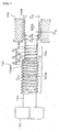
- Figure 1 and Figure 2 relate to an embodiment of the present invention.
- Figure 1 shows a bolt having a guide boss according to an embodiment of the present invention.
- said bolt (101) consists of a head (102), an axle (103), a thread (103A) formed on the circumference of said axle (103); and a guide boss (104) formed at the end of said axle (103).
- Said thread has an incomplete thread from the front most end S to a fixed thread position, said incomplete thread the height of which is gradually increacing from 0 to the height of said complete thread has a range of an angle on the circumferemce of said axle between 50° and 100° .
- the external diameter Db of said guide boss (104) is set to be a little smaller than the internal diameter Dn of a nut (105) in which said bolt (101) is screwed.
- said external diameter Db of said guide boss (104) is set to be a little larger than the root diameter Dv (diameter of the root of the thread) of the thread (103A) of said axle (103).
- the end of said guide boss (104) is beveled.
- a spiral guide groove (104A) is formed on the circumference of said guide boss (104).
- said spiral guide groove (104A) of said guide boss (104) is deeper than the thread (103A) of said axle (103) except at both end parts of said spiral guide groove (104A) and preferably the depth of said spiral guide groove (104A) is set to be between 10 and 70% of the internal thread (105B) of a nut (105) in which said bolt (101) is screwed.
- said spiral guide groove (104A) is set to be gradually shallower toward said axle (103) so that the root (104B) of said spiral guide groove (104A) is situated at the same level as the root (103B) of said thread (103A) of said axle (103).
- the oblique screwing of said bolt (101) is amended and the thread (103A) of said bolt (101) and the thread (105B) of said nut normally engage together to prevent the encroaching, the seizure, or the racing caused by the oblique screwing of the bolt. Also, the encroaching caused by the oblique screwing of the bolt is more effectively prevented by said incomplete thread having the range of the angle on the circumference of said axle between 50° and 100° .
- a guide thread is formed on the circumference of said guide boss instead of said spiral guide groove.
- said guide thread of said guide boss engages with the thread of the nut to introduce the thread of the nut into the thread of the bolt. Nevertheless, introducing the thread of the nut into the spiral guide groove of the guide boss is more smoothly carried out without any obstruction between the threads compared to the case of introducing the thread of the nut into the guide thread of the guide boss.
- the rear most end E of the spiral guide groove (104A) may be set to be situated over the front most end of the thread (103A) between the threads (103A).
- the shape of the head (102) of the bolt may not be limited to only hexagon shape and also a flange may be attached to the head or stud bolt which is also within the scope of the present invention.
Landscapes
- Engineering & Computer Science (AREA)
- General Engineering & Computer Science (AREA)
- Mechanical Engineering (AREA)
- Transmission Devices (AREA)
- Dowels (AREA)
- Details Of Spanners, Wrenches, And Screw Drivers And Accessories (AREA)
- Clamps And Clips (AREA)
- Connection Of Plates (AREA)
Claims (4)
- Bolzen (101), die einen Schaft (103) mit einem Gewinde (103A) und einen an einem Ende der Schraube (101) gebildeten Führungszapfen (104) hat,
wobei die Höhe des Gewindes (103A) an seinem vordersten Ende (S) proximal zum Führungszapfen (104) von null auf den vollen Höhendurchmesser des Gewindes in einem Umfangswinkel im Bereich von 50° bis 100° allmählich zunimmt, und
der Führungszapfen (104) einen konstanten Außendurchmesser (Db) hat, der kleiner als der Durchmesser des Gewindes (103A) ist, und
eine Spiralführungsnut (104A) auf dem Führungszapfen (104) gebildet ist,
wobei die Führungsnut (104A) mit dem Grund (103B) des Gewindes (103A) verbunden ist und die gleiche Steigung wie das Gewinde (103A) hat, wobei die Führungsnut (104A) tiefer als das Gewinde (103A) außer an ihren beiden Endteilen ist. - Bolzen nach Anspruch 1, wobei die Spiralführungsnut (104A) zum Schaft (103) an ihrem hintersten Ende (E), das mit dem Grund (103B) des Gewindes (103A) verbunden ist, allmählich flacher wird, so daß der Grund der Spiralführungsnut (104A) auf der gleichen Tiefe wie der Grund (103B) des Gewindes (103A) endet.
- Bolzen nach Anspruch 2, wobei die Tiefe der Spiralführungsnut (104A) außer an ihren beiden Endteilen zwischen 10 und 70 % der Tiefe des Gewindes (105B) eines Innengewindes (105A) liegt, in das der Bolzen (101) eingeschraubt werden kann.
- System mit
einem Innengewinde (105A) und
einem Bolzen (101) nach einem der Ansprüche 1 bis 3,
wobei der Bolzen (101) in das Innengewinde (105A) eingeschraubt werden kann.
Applications Claiming Priority (4)
| Application Number | Priority Date | Filing Date | Title |
|---|---|---|---|
| JP19862599 | 1999-07-13 | ||
| JP19862599 | 1999-07-13 | ||
| JP2000084534A JP3469846B2 (ja) | 1999-07-13 | 2000-03-24 | 案内ボス部溝付ボルト |
| JP2000084534 | 2000-03-24 |
Publications (3)
| Publication Number | Publication Date |
|---|---|
| EP1069324A2 EP1069324A2 (de) | 2001-01-17 |
| EP1069324A3 EP1069324A3 (de) | 2002-05-15 |
| EP1069324B1 true EP1069324B1 (de) | 2006-07-19 |
Family
ID=26511087
Family Applications (1)
| Application Number | Title | Priority Date | Filing Date |
|---|---|---|---|
| EP00110903A Expired - Lifetime EP1069324B1 (de) | 1999-07-13 | 2000-05-24 | Bolzen |
Country Status (5)
| Country | Link |
|---|---|
| US (1) | US6296432B1 (de) |
| EP (1) | EP1069324B1 (de) |
| JP (1) | JP3469846B2 (de) |
| CA (1) | CA2313288C (de) |
| DE (1) | DE60029393T2 (de) |
Families Citing this family (15)
| Publication number | Priority date | Publication date | Assignee | Title |
|---|---|---|---|---|
| JP2002213425A (ja) * | 2000-11-14 | 2002-07-31 | Meidoo:Kk | ボルト |
| US7334975B2 (en) * | 2001-08-20 | 2008-02-26 | Maclean-Fogg Company | Fastener assembly |
| US7438512B2 (en) * | 2001-08-20 | 2008-10-21 | Maclean-Fogg Company | U-bolt assembly |
| JP4171631B2 (ja) * | 2001-09-25 | 2008-10-22 | 株式会社青山製作所 | ボルト |
| JP3816919B2 (ja) * | 2003-11-13 | 2006-08-30 | 將代 小黒 | ボルト、及び、接合金物。 |
| US20050227800A1 (en) * | 2004-04-09 | 2005-10-13 | Borgwarner Inc. | Arch-loaded guide bracket design |
| US7326014B2 (en) * | 2004-04-21 | 2008-02-05 | Illinois Tool Works, Inc | Interactive fit screw thread |
| DE102008042141A1 (de) | 2008-09-16 | 2010-03-25 | Kamax-Werke Rudolf Kellermann Gmbh & Co. Kg | Selbstzentrierende Schraube |
| JP5460454B2 (ja) * | 2010-05-06 | 2014-04-02 | 本田技研工業株式会社 | 車体とエンジンの結合方法 |
| US9835193B2 (en) * | 2014-05-01 | 2017-12-05 | Research Engineering & Manufacturing Inc. | Fastener system comprising an externally threaded bolt and an internally threaded nut for the avoidance of cross-threading of the mating threads during assembly |
| FR3039231B1 (fr) * | 2015-07-22 | 2018-03-16 | Rdo Alpha | Boulon a devissage freine |
| WO2018088218A1 (ja) | 2016-11-11 | 2018-05-17 | 株式会社メイドー | ボルト |
| EP3604834B1 (de) * | 2017-03-23 | 2023-10-18 | Meidoh Co., Ltd. | Bolzen |
| IT201700077422A1 (it) * | 2017-07-10 | 2019-01-10 | Mr Ind Fasteners S R L | Perno filettato |
| DE102018114984A1 (de) | 2018-06-21 | 2019-12-24 | Ejot Gmbh & Co. Kg | Schraube zur Verschraubung in Kunststoff |
Family Cites Families (9)
| Publication number | Priority date | Publication date | Assignee | Title |
|---|---|---|---|---|
| US2021704A (en) * | 1932-01-25 | 1935-11-19 | United Screw And Bolt Corp | Screw |
| US2113600A (en) * | 1937-04-19 | 1938-04-12 | Illinois Tool Works | Threaded fastener |
| US3527136A (en) * | 1969-02-27 | 1970-09-08 | Standard Pressed Steel Co | Self-retained thread rolling screw |
| US3878759A (en) * | 1972-12-29 | 1975-04-22 | Textron Inc | Bi-lobular self-thread forming fastener |
| DE3922684A1 (de) * | 1989-03-23 | 1991-01-24 | Jaeger Eberhard Gmbh | Loch- und gewindeformende schraube |
| FR2697875B1 (fr) * | 1992-11-10 | 1994-12-09 | Renault | Vis à extrémité ogivale. |
| JP3013395U (ja) | 1995-01-06 | 1995-07-11 | 直美 寺田 | 軟質性管状容器 |
| EA000161B1 (ru) * | 1995-07-21 | 1998-10-29 | Майкл А. Гарвер | Самоцентрирующееся крепежное изделие с предохранением от срезания резьбы |
| US6089806A (en) * | 1999-01-25 | 2000-07-18 | Conti Fasteners | Blank for self-tapping fastener |
-
2000
- 2000-03-24 JP JP2000084534A patent/JP3469846B2/ja not_active Expired - Fee Related
- 2000-05-24 EP EP00110903A patent/EP1069324B1/de not_active Expired - Lifetime
- 2000-05-24 DE DE60029393T patent/DE60029393T2/de not_active Expired - Lifetime
- 2000-06-02 US US09/586,063 patent/US6296432B1/en not_active Expired - Lifetime
- 2000-06-30 CA CA002313288A patent/CA2313288C/en not_active Expired - Fee Related
Also Published As
| Publication number | Publication date |
|---|---|
| US6296432B1 (en) | 2001-10-02 |
| JP2001082431A (ja) | 2001-03-27 |
| CA2313288A1 (en) | 2001-01-13 |
| DE60029393D1 (de) | 2006-08-31 |
| DE60029393T2 (de) | 2007-07-12 |
| EP1069324A3 (de) | 2002-05-15 |
| JP3469846B2 (ja) | 2003-11-25 |
| EP1069324A2 (de) | 2001-01-17 |
| CA2313288C (en) | 2006-06-06 |
Similar Documents
| Publication | Publication Date | Title |
|---|---|---|
| EP1069324B1 (de) | Bolzen | |
| EP1205675B1 (de) | Schraube | |
| US6796761B2 (en) | Bolt and nut | |
| US4258607A (en) | Vibration resistant screw | |
| US6328515B1 (en) | Fastener with anti-cross-threading point and method of assembly | |
| EP1491777A1 (de) | Manipulationssichere schraube, kombination mit schraubendrehereinsatz und pressstempel zur herstellung der manipulationssicheren schraube | |
| US9664223B2 (en) | Seizure prevention bolt | |
| US9267528B2 (en) | Tapping screw | |
| EP0972953A3 (de) | Bolzen | |
| CA2281313C (en) | Thread insert having detachable tongue | |
| JPH09184506A (ja) | タッピンねじ | |
| JP3755966B2 (ja) | 杭の継手部構造 | |
| US10660680B2 (en) | Bone treating device, bone treating screw and bone treating plate | |
| CA2144394A1 (en) | Insert nut and fastener | |
| EP1455098A2 (de) | Ankerschraube | |
| JP3877746B2 (ja) | 杭の継手部構造 | |
| JPH1143936A (ja) | 杭の継手部構造 | |
| JP3048317B2 (ja) | ボルト及びこのボルトとナットを用いた締結装置 | |
| CA2320457C (en) | Nut, bolt, and thread unit of female and male thread members | |
| EP3604834B1 (de) | Bolzen | |
| JPS6121607Y2 (de) | ||
| JPH0625564B2 (ja) | 複合ねじ | |
| JP2007327635A (ja) | ボルト及び転造加工ダイス | |
| JPS5920410B2 (ja) | 自己タツプフオ−ミングねじの成型法 | |
| JPH0532646Y2 (de) |
Legal Events
| Date | Code | Title | Description |
|---|---|---|---|
| PUAI | Public reference made under article 153(3) epc to a published international application that has entered the european phase |
Free format text: ORIGINAL CODE: 0009012 |
|
| AK | Designated contracting states |
Kind code of ref document: A2 Designated state(s): AT BE CH CY DE DK ES FI FR GB GR IE IT LI LU MC NL PT SE |
|
| AX | Request for extension of the european patent |
Free format text: AL;LT;LV;MK;RO;SI |
|
| PUAL | Search report despatched |
Free format text: ORIGINAL CODE: 0009013 |
|
| AK | Designated contracting states |
Kind code of ref document: A3 Designated state(s): AT BE CH CY DE DK ES FI FR GB GR IE IT LI LU MC NL PT SE |
|
| AX | Request for extension of the european patent |
Free format text: AL;LT;LV;MK;RO;SI |
|
| RIC1 | Information provided on ipc code assigned before grant |
Free format text: 7F 16B 35/04 A, 7F 16B 5/04 B |
|
| 17P | Request for examination filed |
Effective date: 20020712 |
|
| AKX | Designation fees paid |
Designated state(s): DE FR GB IT NL |
|
| 17Q | First examination report despatched |
Effective date: 20030807 |
|
| GRAP | Despatch of communication of intention to grant a patent |
Free format text: ORIGINAL CODE: EPIDOSNIGR1 |
|
| GRAS | Grant fee paid |
Free format text: ORIGINAL CODE: EPIDOSNIGR3 |
|
| GRAA | (expected) grant |
Free format text: ORIGINAL CODE: 0009210 |
|
| AK | Designated contracting states |
Kind code of ref document: B1 Designated state(s): DE FR GB IT NL |
|
| PG25 | Lapsed in a contracting state [announced via postgrant information from national office to epo] |
Ref country code: IT Free format text: LAPSE BECAUSE OF FAILURE TO SUBMIT A TRANSLATION OF THE DESCRIPTION OR TO PAY THE FEE WITHIN THE PRE;WARNING: LAPSES OF ITALIAN PATENTS WITH EFFECTIVE DATE BEFORE 2007 MAY HAVE OCCURRED AT ANY TIME BEFORE 2007. THE CORRECT EFFECTIVE DATE MAY BE DIFFERENT FROM THE ONE RECORDED.SCRIBED TIME-LIMIT Effective date: 20060719 |
|
| REG | Reference to a national code |
Ref country code: GB Ref legal event code: FG4D |
|
| REF | Corresponds to: |
Ref document number: 60029393 Country of ref document: DE Date of ref document: 20060831 Kind code of ref document: P |
|
| ET | Fr: translation filed | ||
| PLBE | No opposition filed within time limit |
Free format text: ORIGINAL CODE: 0009261 |
|
| STAA | Information on the status of an ep patent application or granted ep patent |
Free format text: STATUS: NO OPPOSITION FILED WITHIN TIME LIMIT |
|
| 26N | No opposition filed |
Effective date: 20070420 |
|
| REG | Reference to a national code |
Ref country code: FR Ref legal event code: PLFP Year of fee payment: 17 |
|
| PGFP | Annual fee paid to national office [announced via postgrant information from national office to epo] |
Ref country code: GB Payment date: 20160531 Year of fee payment: 17 |
|
| PGFP | Annual fee paid to national office [announced via postgrant information from national office to epo] |
Ref country code: DE Payment date: 20160629 Year of fee payment: 17 |
|
| REG | Reference to a national code |
Ref country code: FR Ref legal event code: PLFP Year of fee payment: 18 |
|
| PGFP | Annual fee paid to national office [announced via postgrant information from national office to epo] |
Ref country code: NL Payment date: 20170519 Year of fee payment: 18 |
|
| PGFP | Annual fee paid to national office [announced via postgrant information from national office to epo] |
Ref country code: FR Payment date: 20170519 Year of fee payment: 18 |
|
| PGFP | Annual fee paid to national office [announced via postgrant information from national office to epo] |
Ref country code: IT Payment date: 20170525 Year of fee payment: 18 |
|
| REG | Reference to a national code |
Ref country code: DE Ref legal event code: R119 Ref document number: 60029393 Country of ref document: DE |
|
| GBPC | Gb: european patent ceased through non-payment of renewal fee |
Effective date: 20170524 |
|
| PG25 | Lapsed in a contracting state [announced via postgrant information from national office to epo] |
Ref country code: GB Free format text: LAPSE BECAUSE OF NON-PAYMENT OF DUE FEES Effective date: 20170524 Ref country code: DE Free format text: LAPSE BECAUSE OF NON-PAYMENT OF DUE FEES Effective date: 20171201 |
|
| REG | Reference to a national code |
Ref country code: NL Ref legal event code: MM Effective date: 20180601 |
|
| PG25 | Lapsed in a contracting state [announced via postgrant information from national office to epo] |
Ref country code: FR Free format text: LAPSE BECAUSE OF NON-PAYMENT OF DUE FEES Effective date: 20180531 Ref country code: NL Free format text: LAPSE BECAUSE OF NON-PAYMENT OF DUE FEES Effective date: 20180601 Ref country code: IT Free format text: LAPSE BECAUSE OF NON-PAYMENT OF DUE FEES Effective date: 20180524 |