EP1069298B1 - Control method for an internal combustion engine in order to compensate valve failure - Google Patents
Control method for an internal combustion engine in order to compensate valve failure Download PDFInfo
- Publication number
- EP1069298B1 EP1069298B1 EP00401883A EP00401883A EP1069298B1 EP 1069298 B1 EP1069298 B1 EP 1069298B1 EP 00401883 A EP00401883 A EP 00401883A EP 00401883 A EP00401883 A EP 00401883A EP 1069298 B1 EP1069298 B1 EP 1069298B1
- Authority
- EP
- European Patent Office
- Prior art keywords
- valve
- engine
- cylinder
- charge
- valves
- Prior art date
- Legal status (The legal status is an assumption and is not a legal conclusion. Google has not performed a legal analysis and makes no representation as to the accuracy of the status listed.)
- Expired - Lifetime
Links
- 238000002485 combustion reaction Methods 0.000 title claims description 43
- 238000000034 method Methods 0.000 title claims description 32
- 239000000446 fuel Substances 0.000 claims description 12
- 239000007789 gas Substances 0.000 claims description 11
- 239000000203 mixture Substances 0.000 claims description 8
- 238000006073 displacement reaction Methods 0.000 claims description 4
- 238000005259 measurement Methods 0.000 claims description 3
- 238000005086 pumping Methods 0.000 claims description 3
- 238000004458 analytical method Methods 0.000 description 3
- 230000001066 destructive effect Effects 0.000 description 3
- 238000007726 management method Methods 0.000 description 3
- 230000006835 compression Effects 0.000 description 2
- 238000007906 compression Methods 0.000 description 2
- 238000010790 dilution Methods 0.000 description 2
- 239000012895 dilution Substances 0.000 description 2
- 235000001954 papillon Nutrition 0.000 description 2
- 244000229285 papillon Species 0.000 description 2
- 206010016754 Flashback Diseases 0.000 description 1
- 206010020710 Hyperphagia Diseases 0.000 description 1
- 239000003054 catalyst Substances 0.000 description 1
- 238000005474 detonation Methods 0.000 description 1
- 238000010586 diagram Methods 0.000 description 1
- 238000002347 injection Methods 0.000 description 1
- 239000007924 injection Substances 0.000 description 1
- 230000010355 oscillation Effects 0.000 description 1
- 235000020830 overeating Nutrition 0.000 description 1
- 230000002269 spontaneous effect Effects 0.000 description 1
Images


Classifications
-
- F—MECHANICAL ENGINEERING; LIGHTING; HEATING; WEAPONS; BLASTING
- F02—COMBUSTION ENGINES; HOT-GAS OR COMBUSTION-PRODUCT ENGINE PLANTS
- F02D—CONTROLLING COMBUSTION ENGINES
- F02D13/00—Controlling the engine output power by varying inlet or exhaust valve operating characteristics, e.g. timing
- F02D13/02—Controlling the engine output power by varying inlet or exhaust valve operating characteristics, e.g. timing during engine operation
- F02D13/0203—Variable control of intake and exhaust valves
- F02D13/0215—Variable control of intake and exhaust valves changing the valve timing only
-
- F—MECHANICAL ENGINEERING; LIGHTING; HEATING; WEAPONS; BLASTING
- F01—MACHINES OR ENGINES IN GENERAL; ENGINE PLANTS IN GENERAL; STEAM ENGINES
- F01L—CYCLICALLY OPERATING VALVES FOR MACHINES OR ENGINES
- F01L9/00—Valve-gear or valve arrangements actuated non-mechanically
- F01L9/20—Valve-gear or valve arrangements actuated non-mechanically by electric means
-
- F—MECHANICAL ENGINEERING; LIGHTING; HEATING; WEAPONS; BLASTING
- F02—COMBUSTION ENGINES; HOT-GAS OR COMBUSTION-PRODUCT ENGINE PLANTS
- F02D—CONTROLLING COMBUSTION ENGINES
- F02D13/00—Controlling the engine output power by varying inlet or exhaust valve operating characteristics, e.g. timing
- F02D13/02—Controlling the engine output power by varying inlet or exhaust valve operating characteristics, e.g. timing during engine operation
- F02D13/0253—Fully variable control of valve lift and timing using camless actuation systems such as hydraulic, pneumatic or electromagnetic actuators, e.g. solenoid valves
-
- F—MECHANICAL ENGINEERING; LIGHTING; HEATING; WEAPONS; BLASTING
- F02—COMBUSTION ENGINES; HOT-GAS OR COMBUSTION-PRODUCT ENGINE PLANTS
- F02D—CONTROLLING COMBUSTION ENGINES
- F02D13/00—Controlling the engine output power by varying inlet or exhaust valve operating characteristics, e.g. timing
- F02D13/02—Controlling the engine output power by varying inlet or exhaust valve operating characteristics, e.g. timing during engine operation
- F02D13/0257—Independent control of two or more intake or exhaust valves respectively, i.e. one of two intake valves remains closed or is opened partially while the other is fully opened
-
- F—MECHANICAL ENGINEERING; LIGHTING; HEATING; WEAPONS; BLASTING
- F02—COMBUSTION ENGINES; HOT-GAS OR COMBUSTION-PRODUCT ENGINE PLANTS
- F02D—CONTROLLING COMBUSTION ENGINES
- F02D41/00—Electrical control of supply of combustible mixture or its constituents
- F02D41/0002—Controlling intake air
-
- F—MECHANICAL ENGINEERING; LIGHTING; HEATING; WEAPONS; BLASTING
- F02—COMBUSTION ENGINES; HOT-GAS OR COMBUSTION-PRODUCT ENGINE PLANTS
- F02D—CONTROLLING COMBUSTION ENGINES
- F02D41/00—Electrical control of supply of combustible mixture or its constituents
- F02D41/22—Safety or indicating devices for abnormal conditions
- F02D41/221—Safety or indicating devices for abnormal conditions relating to the failure of actuators or electrically driven elements
-
- F—MECHANICAL ENGINEERING; LIGHTING; HEATING; WEAPONS; BLASTING
- F01—MACHINES OR ENGINES IN GENERAL; ENGINE PLANTS IN GENERAL; STEAM ENGINES
- F01L—CYCLICALLY OPERATING VALVES FOR MACHINES OR ENGINES
- F01L2201/00—Electronic control systems; Apparatus or methods therefor
-
- F—MECHANICAL ENGINEERING; LIGHTING; HEATING; WEAPONS; BLASTING
- F02—COMBUSTION ENGINES; HOT-GAS OR COMBUSTION-PRODUCT ENGINE PLANTS
- F02D—CONTROLLING COMBUSTION ENGINES
- F02D41/00—Electrical control of supply of combustible mixture or its constituents
- F02D41/0002—Controlling intake air
- F02D2041/001—Controlling intake air for engines with variable valve actuation
-
- Y—GENERAL TAGGING OF NEW TECHNOLOGICAL DEVELOPMENTS; GENERAL TAGGING OF CROSS-SECTIONAL TECHNOLOGIES SPANNING OVER SEVERAL SECTIONS OF THE IPC; TECHNICAL SUBJECTS COVERED BY FORMER USPC CROSS-REFERENCE ART COLLECTIONS [XRACs] AND DIGESTS
- Y02—TECHNOLOGIES OR APPLICATIONS FOR MITIGATION OR ADAPTATION AGAINST CLIMATE CHANGE
- Y02T—CLIMATE CHANGE MITIGATION TECHNOLOGIES RELATED TO TRANSPORTATION
- Y02T10/00—Road transport of goods or passengers
- Y02T10/10—Internal combustion engine [ICE] based vehicles
- Y02T10/12—Improving ICE efficiencies
-
- Y—GENERAL TAGGING OF NEW TECHNOLOGICAL DEVELOPMENTS; GENERAL TAGGING OF CROSS-SECTIONAL TECHNOLOGIES SPANNING OVER SEVERAL SECTIONS OF THE IPC; TECHNICAL SUBJECTS COVERED BY FORMER USPC CROSS-REFERENCE ART COLLECTIONS [XRACs] AND DIGESTS
- Y02—TECHNOLOGIES OR APPLICATIONS FOR MITIGATION OR ADAPTATION AGAINST CLIMATE CHANGE
- Y02T—CLIMATE CHANGE MITIGATION TECHNOLOGIES RELATED TO TRANSPORTATION
- Y02T10/00—Road transport of goods or passengers
- Y02T10/10—Internal combustion engine [ICE] based vehicles
- Y02T10/40—Engine management systems
Definitions
- the present invention relates to a combustion engine, in particular a heat engine of a motor vehicle.
- the invention relates more particularly to a method of control of a four-stroke combustion engine for compensate for a valve failure.
- the invention relates more particularly to a motor with combustion including intake and exhaust valves of each cylinder are mounted on springs and controlled individually by means of a linear actuator, in particular of an electromagnetic actuator, each actuator of a valve being connected to an electronic control unit of the engine.
- the invention aims to propose a control method of such an engine without camshafts in order to compensate for the valve failure.
- each cylinder having more than one valve intake and several exhaust valves.
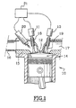
- FIG. 1 shows a cylinder 10 of an engine internal combustion four-stroke and the part of which upper forms a combustion chamber 12 delimited by a movable piston 14 and by a cylinder head 15.
- Cylinder 10 has several intake valves and several exhaust valves. We have represented a single intake valve 18 and single valve exhaust 19.
- the cylinder 10 is supplied with air / fuel mixture by an intake circuit 16 which opens into the combustion 12 through intake valves 18 whose movements are controlled by actuators linear electromagnetic 11 in order to shut off or not the communications between the intake circuit 16 and the chamber combustion 12.
- An exhaust circuit 17 is provided for evacuation gases burnt out of the combustion chamber 12 through exhaust valves 19 also controlled by electromagnetic linear actuators 13.
- Each valve is mounted on two springs (not roughly equivalent in strength, one tending to keep the valve in the closed position, the other tending to keep in the open position.
- control of the intake valves 18 and exhaust 19 is provided by an electronic unit of control 21 which controls the actuators 11, 13, and which also controls fuel injection, here indirect, at by means of an injector 20, as well as the ignition by means a candle (not shown).
- the electronic control unit 21 comprises in particular means for storing one or more engine operating maps, each of which determines the different parameters and states of the engine for a range of operating points, particularly with a view to determine the engine rotation speed, the load of each cylinder, etc.
- the electronic control unit 21 receives signals representative of operating parameters such as the engine speed, atmospheric pressure, pressure in each cylinder, the flow rate of the intake gases and / or exhaust, instantaneous torque supplied, etc.
- the electronic control unit 21 analyzes in particular electrical characteristics representative of the correct operation of the actuators 11, 13.
- the shape of the current curve supplying an actuator changes appreciably, depending on the valve displacement dynamics, with differences depending on the direction of travel.
- This special feature is operated by the electronic control unit 21 to detect the failure of a valve which, under the action of the two springs, remains open in the equilibrium position at mid-stroke.
- electronic control unit 21 analysis of the displacement measurements of the valves or actuators 11, 13.
- the piston 14 performs a descending race from top dead center TDC to point dead low PMB and then it does an upward run of the point low dead PMB towards top dead center TDC.
- the electronic control unit 21 If the electronic control unit 21 detects the failure of a valve, it controls the actuators 11, 13, the injector 20 and the spark plug, so as to compensate for this failure.
- the management of these elements aims to prevent the appearance of combustion or make the latter little Energy.
- the electronic control unit 21 As soon as the electronic control unit 21 detects the failure of an intake valve 18, it controls, on the offending cylinder, the cut off of the fuel supply, and switching off the ignition if the engine is fitted with a compatible ignition device.
- compatible ignition device is meant that the ignition device includes an ignition coil cylinder, or else it has an ignition coil to two cylinders but also that the operating cycles of each of these two cylinders are offset by one turn crankshaft.
- the electronic control unit determines the risk of combustion.
- the risk of combustion is effective if ignition could not be shut off, or if a hot spot is capable to initiate combustion.
- the electronic control unit 21 considers that the ignition and power cuts are sufficient to prevent combustion.
- the electronic control unit 21 controls the cylinder operation in a first degraded mode MD1.
- the first degraded mode MD1 consists on the one hand in keep the exhaust valves 19 closed, and on the other hand, to order either the opening or the closing, valid inlet valves 18. We also maintain ignition and fuel supply cuts.
- the closing of the exhaust valves 19 aims to avoid any fresh air supply to the circuit exhaust 17.
- control electronics 21 identifies the position in which is the piston 14.
- valve failure has been detected 18 when it is closed, the piston 14 is then in its downstroke, or near the bottom dead center PMB.
- the unit control electronics 21 then command, as soon as possible possible, the closing of the valid inlet valves 18 and the opening of the exhaust valves 19.
- This command is to limit the admission of carburetted charge, by closing the intake valves 18 valid, and to dilute the charge admitted by burnt gases introduced by opening the exhaust valves 19.
- the combustion chamber 12 is thus filled with a mixture of air and exhaust gases, with a very strong proportion of these. The mixture is very little combustible.
- either the unit control electronics 21 When the piston 14 is near the point dead low PMB or in its upward stroke, either the unit control electronics 21 then holds the valves exhaust 19 open, i.e. the electronic unit of command 21 controls the closing of the valves exhaust 19.
- the unit control electronics 21 starts a discount program in movement of the faulty valve. During this program, the exhaust valves 19 remain closed and the valid intake valves 18 remain open.
- the electronic unit 21 controls the resumption of operation normal from cylinder 10 to the next synchronization signal with the other cylinders.
- the unit control electronics 21 controls the operation of the cylinder 10 according to the first degraded mode MD1 until the faulty valve is working again.
- the electronic control unit 21 As soon as the electronic control unit 21 detects the failure of an exhaust valve 19, it controls the cut off the fuel supply, and cut off ignition if the engine is fitted with an ignition device compatible.
- This step of the process is identical to that implemented operates in the case of a faulty intake valve 18.
- the electronic control unit 21 then identifies the position in which the intake valves 18 are located.
- the electronic control unit 21 controls the operation of the cylinder 10 according to a second degraded mode MD2.
- This degraded mode MD2 corresponds to an operation in which the intake valves 18 are closed and the 19 valid exhaust valves are open.
- unit 21 controls the closing of the intake valves 18 the most as early as possible.
- the electronic control unit 21 controls the most as soon as possible, closing from intake valves 18 and the opening of the valid exhaust valves 19. Then, during the upward stroke of the piston 14, the electronic unit 21 keeps the exhaust valves 19 valid open.
- the unit control electronics 21 starts a discount program in movement of the faulty valve. During this program, the intake valves 18 remain closed and the 19 valid exhaust valves remain open.
- the electronic unit 21 controls the resumption of operation normal from cylinder 10 to the next synchronization signal with the other cylinders.
- the unit control electronics 21 controls the operation of the cylinder 10 according to the second degraded mode MD2 until the faulty valve is working again.
- At least one valve remains open, so that the flows and pressures in cylinder 10 do not do not, or only slightly, disturb the oscillations of resetting faulty valve movement.
- each cylinder 10 comprises several intake valves 18 and a single valve exhaust 19, or a single intake valve 18 and several exhaust valves 19.
- the method according to the invention also makes it possible to ensure a diagnostic function since, when the failure of a valve on cylinder 10, we can advise the user to perform a mechanical examination, for example by lighting up an alert light on the dashboard.
Landscapes
- Engineering & Computer Science (AREA)
- Mechanical Engineering (AREA)
- General Engineering & Computer Science (AREA)
- Chemical & Material Sciences (AREA)
- Combustion & Propulsion (AREA)
- Physics & Mathematics (AREA)
- Electromagnetism (AREA)
- Output Control And Ontrol Of Special Type Engine (AREA)
- Valve Device For Special Equipments (AREA)
- Electrical Control Of Air Or Fuel Supplied To Internal-Combustion Engine (AREA)
Description
La présente invention concerne un moteur à combustion, notamment un moteur thermique de véhicule automobile.The present invention relates to a combustion engine, in particular a heat engine of a motor vehicle.
L'invention concerne plus particulièrement un procédé de commande d'un moteur à combustion à quatre temps en vue de compenser la défaillance d'une soupape.The invention relates more particularly to a method of control of a four-stroke combustion engine for compensate for a valve failure.
L'invention concerne plus particulièrement un moteur à combustion dont les soupapes d'admission et d'échappement de chaque cylindre sont montées sur ressorts et commandées individuellement au moyen d'un actionneur linéaire, notamment d'un actionneur électromagnétique, chaque actionneur d'une soupape étant relié à une unité électronique de commande du moteur.The invention relates more particularly to a motor with combustion including intake and exhaust valves of each cylinder are mounted on springs and controlled individually by means of a linear actuator, in particular of an electromagnetic actuator, each actuator of a valve being connected to an electronic control unit of the engine.
Un tel moteur à combustion sans arbres à cames, aussi appelé moteur "camless", offre de grandes possibilités pour la commande individualisée des soupapes d'admission et d'échappement indépendamment du ou des diagrammes généraux de distribution du moteur.Such a combustion engine without camshafts, too called "camless" motor, offers great possibilities for the individual control of the intake valves and exhaust regardless of diagram (s) distribution of the engine.
Dans les moteurs "camless" on ne peut pas se garantir totalement de la "perte d'une soupape". Il est possible que le mouvement d'une soupape, pour une raison inconnue, n'ait pas suivi la loi de commande de l'unité électronique de commande du moteur. Ainsi, sous l'action des ressorts, la soupape reste ouverte en position d'équilibre à mi-course.In "camless" motors we cannot guarantee totally from the "loss of a valve". It is possible that the valve movement, for some unknown reason, did not followed the control law of the electronic control unit of the motor. Thus, under the action of the springs, the valve remains open in balance position halfway.
Quand survient l'allumage, même sans compression, une combustion peut se déclencher et se propager dans le circuit d'admission ou d'échappement. Cet incident peut générer des retours de flamme et/ou des détonations destructrices.When ignition occurs, even without compression, a combustion can start and spread in the circuit intake or exhaust. This incident may generate flashbacks and / or destructive detonations.
L'invention vise à proposer un procédé de commande d'un tel moteur sans arbres à cames en vue de compenser la défaillance d'une soupape.The invention aims to propose a control method of such an engine without camshafts in order to compensate for the valve failure.
Dans ce but, l'invention propose un procédé de commande d'un moteur à combustion à quatre temps, du type comportant un circuit d'admission d'air ou de mélange air/carburant et un circuit d'échappement de gaz brûlés qui communiquent avec une chambre de combustion d'au moins un cylindre du moteur, du type dans lequel les communications des circuits d'admission et d'échappement avec la chambre sont susceptibles d'être obturées chacune respectivement par au moins une soupape, respectivement d'admission et d'échappement à ouverture commandée par un actionneur linéaire, notamment par un actionneur électromagnétique, relié à une unité électronique de commande, en vue de compenser la défaillance d'une soupape, caractérisé en ce qu'il consiste, successivement, à :
- a) détecter la soupape défaillante ;
- b) couper l'alimentation en carburant et, si le moteur est du type à allumage commandé que l'on peut couper, à couper l'allumage, sur le cylindre correspondant ;
- c) si une charge a été admise dans la chambre de combustion et qu'il y a un risque de la voir brûler, commander les soupapes valides de façon à, limiter l'admission de charge carburée et diluer la charge admise par des gaz brûlés ;
- d) commander le fonctionnement du cylindre selon un premier mode dégradé si la soupape défaillante est une soupape d'admission, ou selon un second mode dégradé si la soupape défaillante est une soupape d'échappement, jusqu'à ce que le fonctionnement de la soupape défaillante soit à nouveau normal.
- a) detect the faulty valve;
- b) cut the fuel supply and, if the engine is of the spark-ignition type that can be cut, cut the ignition, on the corresponding cylinder;
- c) if a charge has been admitted into the combustion chamber and there is a risk of seeing it burn, control the valid valves so as to limit the admission of carburetted charge and dilute the charge admitted by burnt gases ;
- d) controlling the operation of the cylinder according to a first degraded mode if the faulty valve is an intake valve, or according to a second degraded mode if the faulty valve is an exhaust valve, until the operation of the valve is normal again.
Grâce à un tel procédé, il est extrêmement peu probable qu'il y ait une combustion dans le cylindre dont une soupape est défaillante. En effet, soit on a pu empêcher l'admission d'une charge carburée dans le cylindre, soit on a limité l'admission de charge carburée et dilué cette charge avec des gaz brûlés, ce qui rend le mélange peu combustible. S'il y a une combustion, du fait de la forte dilution, elle est peu énergétique et donc peu destructrice. Thanks to such a process, it is extremely unlikely there is combustion in the cylinder including a valve is failing. Either we were able to prevent admission of a carburetted charge in the cylinder, or we have limited the admission of carburetted charge and diluted this charge with burnt gases, which makes the mixture not very combustible. If there is combustion, due to the high dilution, it is not very energetic and therefore not very destructive.
Selon d'autres caractéristiques de l'invention :
- dans le cas d'une charge admise risquant de brûler, pour limiter cette admission, on commande la fermeture des soupapes d'admission valides le plus tôt possible ;
- dans le cas d'une charge admise risquant de brûler, pour diluer cette charge par des gaz brûlés, on commande l'ouverture des soupapes d'échappement valides le plus tôt possible ;
- dans le cas d'une charge admise risquant de brûler, pendant la course ascendante du piston ou un peu avant, on maintient les soupapes d'échappement valides ouvertes si l'on accepte de refouler la charge vers le circuit d'échappement, ou on commande la fermeture des soupapes d'échappement valides si l'on veut éviter de refouler la charge vers le circuit d'échappement ;
- dans le cas d'une charge admise risquant de brûler, pendant la course ascendante du piston ou un peu avant, on commande l'ouverture des soupapes d'admission valides ;
- le premier mode dégradé correspond à un fonctionnement lors duquel les soupapes d'échappement sont fermées et les soupapes d'admission valides sont, soit ouvertes si l'on cherche à réduire les pertes par pompage, soit fermées si l'on cherche à réduire les perturbations acoustiques dans les circuits d'admission ;
- le second mode dégradé correspond à un fonctionnement lors duquel les soupapes d'admission valides sont fermées et les soupapes d'échappement valides sont ouvertes ;
- pour détecter la défaillance d'une soupape, on analyse des caractéristiques électriques représentatives du bon fonctionnement des actionneurs électromagnétiques, ou on analyse des mesures du déplacement des soupapes ou des actionneurs ;
- après avoir traité le cas d'une charge admise risquant de brûler ou à la fin d'un cycle de fonctionnement selon un des modes dégradés, lorsque le piston se trouve au point mort haut, l'unité électronique de commande lance un programme de remise en mouvement de la soupape défaillante, puis commande le fonctionnement du cylindre selon le mode dégradé prévu, si la soupape est toujours défaillante, ou selon le cycle normal, si la soupape n'est plus défaillante ;
- pendant la durée du programme de remise en mouvement de la soupape défaillante, on maintient au moins une soupape ouverte ;
- si l'allumage est commun à plusieurs cylindres, il est remis en service lorsqu'il n'y a plus de risque de combustion ;
- si le moteur est du type à rapport volumétrique variable, dès que l'on détecte la défaillance d'une soupape sur le cylindre, on force au plus tôt la commande du rapport volumétrique sur le cylindre à une valeur de consigne basse ;
- si le moteur est du type à régulation de la température de l'air à l'admission, dès que l'on détecte la défaillance d'une soupape sur le cylindre on force la commande de température à une valeur de consigne basse ;
- si le moteur est du type à suralimentation, dès que l'on détecte la défaillance d'une soupape sur le cylindre, on inhibe la suralimentation ;
- si le moteur est du type à gestion du couple moteur par un calculateur de contrôle moteur, dès que l'on détecte la défaillance d'une soupape sur le cylindre, on limite le régime du moteur et, si le moteur est muni d'un papillon des gaz motorisé, on limite la charge admise au moyen de la commande du papillon des gaz ;
- lorsque l'on détecte la défaillance d'une soupape sur le cylindre, on conseille à l'utilisateur d'effectuer un examen mécanique, notamment en allumant un voyant d'alerte sur un tableau de bord.
- in the case of an admitted charge liable to burn, to limit this admission, the valid intake valves are closed as soon as possible;
- in the case of an admitted charge liable to burn, to dilute this charge with burnt gases, the opening of the valid exhaust valves is ordered as soon as possible;
- in the case of an admitted charge liable to burn, during the upward stroke of the piston or a little earlier, the valid exhaust valves are kept open if it is agreed to discharge the charge to the exhaust circuit, or controls the closing of the valid exhaust valves if one wants to avoid pushing the load towards the exhaust system;
- in the case of an admitted charge liable to burn, during the upward stroke of the piston or a little earlier, the opening of the valid intake valves is ordered;
- the first degraded mode corresponds to an operation in which the exhaust valves are closed and the valid intake valves are either open if one seeks to reduce pumping losses, or closed if one seeks to reduce acoustic disturbances in the intake circuits;
- the second degraded mode corresponds to an operation in which the valid intake valves are closed and the valid exhaust valves are open;
- to detect the failure of a valve, electrical characteristics representative of the proper functioning of the electromagnetic actuators are analyzed, or measurements of the displacement of the valves or actuators are analyzed;
- after having dealt with the case of an admitted load liable to burn or at the end of an operating cycle in one of the degraded modes, when the piston is in top dead center, the electronic control unit starts a reset program in movement of the faulty valve, then controls the operation of the cylinder according to the degraded mode provided, if the valve is still faulty, or according to the normal cycle, if the valve is no longer faulty;
- at least one valve is kept open for the duration of the program for restoring the movement of the faulty valve;
- if the ignition is common to several cylinders, it is returned to service when there is no longer any risk of combustion;
- if the engine is of the variable volumetric ratio type, as soon as a failure of a valve on the cylinder is detected, the volumetric ratio control on the cylinder is forced as soon as possible to a low set value;
- if the engine is of the type with regulation of the temperature of the intake air, as soon as the failure of a valve on the cylinder is detected, the temperature control is forced to a low set value;
- if the engine is of the supercharged type, as soon as the failure of a valve on the cylinder is detected, the supercharging is inhibited;
- if the engine is of the type with engine torque management by an engine control computer, as soon as the failure of a valve on the cylinder is detected, the engine speed is limited and, if the engine is fitted with a motorized throttle valve, the load allowed is limited by means of the throttle valve control;
- when the failure of a valve on the cylinder is detected, the user is advised to carry out a mechanical examination, in particular by lighting an warning light on a dashboard.
D'autres caractéristiques et avantages de l'invention apparaítront à la lecture de la description détaillée qui suit pour la compréhension de laquelle on se reportera aux dessins annexés dans lesquels :
- la figure 1 est une.vue schématique partielle en coupe d'une partie d'un moteur à combustion interne à soupapes sans arbre à cames et commandé selon un procédé conforme aux enseignements de l'invention ;
- la figure 2 est un ordinogramme pour l'illustration de la mise en oeuvre du procédé selon l'invention dans le cas d'une soupape d'admission défaillante ;
- la figure 3 est un ordinogramme pour l'illustration de la mise en oeuvre du procédé selon l'invention dans le cas d'une soupape d'échappement défaillante.
- Figure 1 is a partial schematic une.vue section of a part of an internal combustion engine with valves without camshaft and controlled according to a method according to the teachings of the invention;
- FIG. 2 is a flow chart for illustrating the implementation of the method according to the invention in the case of a faulty intake valve;
- Figure 3 is a flow chart for illustrating the implementation of the method according to the invention in the case of a faulty exhaust valve.
On expliquera par la suite la mise en oeuvre du procédé selon l'invention dans le cas d'un moteur muni d'au moins un cylindre, chaque cylindre comportant plusieurs soupapes d'admission et plusieurs soupapes d'échappement.The implementation of the method will be explained below. according to the invention in the case of an engine fitted with at least one cylinder, each cylinder having more than one valve intake and several exhaust valves.
Les opérations effectuées pour compenser la défaillance d'une soupape ne concernent que le cylindre incriminé, c'est à dire le cylindre dont une soupape est défaillante. S'il y a d'autres cylindres, on supposera pour les explications qu'ils fonctionnent normalement pendant la défaillance de la soupape.Operations carried out to compensate for the failure of a valve relate only to the cylinder in question, it is say the cylinder with a failed valve. If there is other cylinders, we will assume for the explanations that they operate normally during valve failure.
On a représenté à la figure 1 un cylindre 10 d'un moteur
à combustion interne à quatre temps et dont la partie
supérieure forme une chambre de combustion 12 délimitée par
un piston mobile 14 et par une culasse 15.FIG. 1 shows a
Le cylindre 10 comporte plusieurs soupapes d'admission
et plusieurs soupapes d'échappement. On a représenté une
seule soupape d'admission 18 et une seule soupape
d'échappement 19.
Le cylindre 10 est alimenté en mélange air/carburant par
un circuit d'admission 16 qui débouche dans la chambre de
combustion 12 au travers des soupapes d'admission 18 dont les
déplacements sont commandés par des actionneurs
électromagnétiques linéaires 11 afin d'obturer ou non les
communications entre le circuit d'admission 16 et la chambre
de combustion 12.The
Un circuit d'échappement 17 est prévu pour l'évacuation
des gaz brûlés hors de la chambre de combustion 12 au travers
des soupapes d'échappement 19 également commandées par
des actionneurs linéaires électromagnétiques 13.An
Chaque soupape est montée sur deux ressorts (non représentés) de force sensiblement équivalente, l'un tendant à maintenir la soupape en position fermée, l'autre tendant à la maintenir en position ouverte.Each valve is mounted on two springs (not roughly equivalent in strength, one tending to keep the valve in the closed position, the other tending to keep in the open position.
La commande des soupapes d'admission 18 et
d'échappement 19 est assurée par une unité électronique de
commande 21 qui pilote les actionneurs 11, 13, et qui
commande aussi l'injection de carburant, ici indirecte, au
moyen d'un injecteur 20, de même que l'allumage au moyen
d'une bougie (non représentée).The control of the
L'unité électronique de commande 21 comporte
notamment des moyens de mémorisation d'une ou plusieurs
cartographies de fonctionnement du moteur dont chacune
détermine les différents paramètres et états du moteur pour une
gamme de points de fonctionnement, en vue notamment de
déterminer le régime de rotation du moteur, la charge de
chaque cylindre, etc.The
L'unité électronique de commande 21 reçoit des signaux
représentatifs de paramètres de fonctionnement tels que le
régime du moteur, la pression atmosphérique, la pression dans
chaque cylindre, le débit des gaz d'admission et/ou
d'échappement, le couple instantané fourni, etc.The
L'unité électronique de commande 21 analyse en
particulier des caractéristiques électriques représentatives du
bon fonctionnement des actionneurs 11, 13. The
Par exemple, la forme de la courbe du courant
alimentant un actionneur évolue sensiblement, suivant la
dynamique de déplacement de la soupape, avec des
différences en fonction du sens de déplacement. Cette
particularité est exploitée par l'unité électronique de commande
21 pour détecter la défaillance d'une soupape qui, sous l'action
des deux ressorts, reste ouverte en position d'équilibre à mi-course.For example, the shape of the current curve
supplying an actuator changes appreciably, depending on the
valve displacement dynamics, with
differences depending on the direction of travel. This
special feature is operated by the
Selon une variante de réalisation, pour détecter la
défaillance d'une soupape, l'unité électronique de commande
21 analyse des mesures du déplacement des soupapes ou des
actionneurs 11, 13.According to an alternative embodiment, to detect the
valve failure,
Selon le principe du cycle à quatre temps d'un moteur à
combustion, celui-ci s'effectue en deux rotations du vilebrequin
et en quatre courses du piston 14, les quatre temps du cycle
étant l'admission, la compression, la combustion et
l'échappement.According to the principle of the four-stroke cycle of a
combustion, this takes place in two rotations of the crankshaft
and in four strokes of
Lors d'une rotation du vilebrequin, le piston 14 effectue
une course descendante du point mort haut PMH vers le point
mort bas PMB, puis il effectue une course ascendante du point
mort bas PMB vers le point mort haut PMH.During a rotation of the crankshaft, the
Si l'unité électronique de commande 21 détecte la
défaillance d'une soupape, elle pilote les actionneurs 11, 13,
l'injecteur 20 et la bougie, de façon à compenser cette
défaillance. Le pilotage de ces éléments vise à prévenir
l'apparition de la combustion ou rendre cette dernière peu
énergétique.If the
On a illustré schématiquement à la figure 2 les
différentes étapes du procédé de commande selon l'invention,
dans le cas de la défaillance d'une soupape d'admission 18.Schematically illustrated in Figure 2 the
different stages of the control method according to the invention,
in the event of the failure of an
Dès que l'unité électronique de commande 21 détecte la
défaillance d'une soupape d'admission 18, elle commande, sur
le.cylindre incriminé, la coupure de l'alimentation en carburant,
et la coupure de l'allumage si le moteur est équipé d'un
dispositif d'allumage compatible.As soon as the
Par dispositif d'allumage compatible on entend que le dispositif d'allumage comporte une bobine d'allumage par cylindre, ou bien qu'il comporte une bobine d'allumage pour deux cylindres, mais aussi que les cycles de fonctionnement de chacun de ces deux cylindres sont décalés d'un tour de vilebrequin.By compatible ignition device is meant that the ignition device includes an ignition coil cylinder, or else it has an ignition coil to two cylinders but also that the operating cycles of each of these two cylinders are offset by one turn crankshaft.
L'unité électronique de commande détermine ensuite le risque de combustion. Le risque de combustion est effectif si l'allumage n'a pu être coupé, ou si un point chaud est capable d'initier une combustion.The electronic control unit then determines the risk of combustion. The risk of combustion is effective if ignition could not be shut off, or if a hot spot is capable to initiate combustion.
Supposons que l'unité électronique de commande 21
considère que les coupures de l'allumage et de l'alimentation
sont suffisantes pour éviter la combustion.Suppose that the
L'unité électronique de commande 21 commande le
fonctionnement du cylindre selon un premier mode dégradé
MD1.The
Le premier mode dégradé MD1 consiste d'une part à
maintenir la fermeture des soupapes d'échappement 19 et,
d'autre part, à commander soit l'ouverture, soit la fermeture,
des soupapes d'admission 18 valides. Par ailleurs on maintient
les coupures de l'allumage et de l'alimentation en carburant.The first degraded mode MD1 consists on the one hand in
keep the
La fermeture des soupapes d'échappement 19 vise à
éviter toute alimentation en air frais du circuit
d'échappement 17.The closing of the
Selon le premier mode dégradé MD1, on commande
l'ouverture des soupapes d'admission 18 valides si l'on
souhaite réduire les pertes par pompage. On commande la
fermeture des soupapes d'admission 18 valides si l'on souhaite
réduire les perturbations acoustiques dans le circuit
d'admission 16. Ces perturbations acoustiques sont dues aux
phases successives d'aspiration et de refoulement. According to the first degraded mode MD1, one commands
the opening of the
Supposons que l'unité électronique de commande 21
considère que le risque de combustion est effectif.L'unité
électronique de commande 21 identifie alors la position dans
laquelle se trouve le piston 14.Suppose that the
Si l'on a détecté la défaillance de la soupape
d'admission 18 à son ouverture, le piston 14 se trouve alors au
voisinage du point mort haut PMH.If the valve failure has been detected
Si l'on a détecté la défaillance de la soupape
d'admission 18 à sa fermeture, le piston 14 se trouve alors
dans sa course descendante, ou au voisinage du point mort bas
PMB.If the valve failure has been detected
18 when it is closed, the
Lorsque le piston 14 se trouve au voisinage du point
mort haut PMH ou dans sa course descendante, l'unité
électronique de commande 21 commande alors, le plus tôt
possible, la fermeture des soupapes d'admission 18 valides et
l'ouverture des soupapes d'échappement 19.When the
L'objet de cette commande est de limiter l'admission de
charge carburée, en fermant les soupapes d'admission 18
valides, et de diluer la charge admise par des gaz brûlés
introduits en ouvrant les soupapes d'échappement 19. La
chambre de combustion 12 se trouve ainsi remplie d'un
mélange d'air et de gaz d'échappement, avec une très forte
proportion de ces derniers. Le mélange est très peu
combustible.The purpose of this command is to limit the admission of
carburetted charge, by closing the
Lorsque le piston 14 se trouve au voisinage du point
mort bas PMB ou bien dans sa course ascendante, soit l'unité
électronique de commande 21 maintient alors les soupapes
d'échappement 19 ouvertes, soit l'unité électronique de
commande 21 commande la fermeture des soupapes
d'échappement 19.When the
On commande la fermeture des soupapes
d'échappement 19 si l'on veut éviter de refouler de la charge
non brûlée vers le circuit d'échappement 17. On agit de cette
façon, par exemple si l'on craint que la charge ne brûle au
niveau d'un catalyseur (non représenté) situé à la sortie du
circuit d'échappement 17 et qu'elle ne le détériore.We close the
Si l'on a maintenu les soupapes d'échappement 19
ouvertes, pendant la course ascendante du piston 14, le
mélange est refoulé principalement vers le circuit
d'échappement 17 et, pour une faible partie, vers le circuit
d'admission 16.If the exhaust valves have been maintained 19
open, during the upward stroke of the
Si l'on a commandé la fermeture des soupapes
d'échappement 19 pendant la course ascendante du piston 14,
le mélange est refoulé vers le circuit d'admission 16.If the valves have been closed
Du fait de la forte dilution de la charge carburée, il est peu probable qu'il y ait une combustion et, si elle a lieu, elle est peu énergétique et donc peu destructrice.Due to the high dilution of the fuel charge, it is unlikely to be a combustion and, if it takes place, it is not very energetic and therefore not very destructive.
Lorsque le cycle est complété, c'est à dire que le piston
14 se trouve à nouveau au point mort haut PMH, l'unité
électronique de commande 21 lance un programme de remise
en mouvement de la soupape défaillante. Pendant ce
programme, les soupapes d'échappement 19 restent fermées et
les soupapes d'admission 18 valides restent ouvertes.When the cycle is completed, that is to say that the
Des programmes de remise en mouvement d'une soupape sont connus. On peut par exemple exciter à nouveau électriquement l'actionneur de la soupape défaillante.Restoration programs of a valve are known. We can for example excite again electrically the valve actuator has failed.
Par ailleurs, le risque de combustion étant passé, l'allumage commun à plusieurs cylindres peut être rétabli.Furthermore, the risk of combustion having passed, the ignition common to several cylinders can be restored.
Si la soupape n'est plus défaillante, l'unité électronique
de commande 21 commande la reprise du fonctionnement
normal du cylindre 10 au prochain signal de synchronisation
avec les autres cylindres.If the valve is no longer faulty, the
Si la soupape est toujours défaillante, l'unité
électronique de commande 21 commande le fonctionnement du
cylindre 10 selon le premier mode dégradé MD1 jusqu'à ce que
la soupape défaillante fonctionne de nouveau.If the valve still fails, the
On note que pendant le fonctionnement selon le premier
mode dégradé MD1, lorsque le piston 14 se trouve au point
mort haut PMH, l'unité électronique lance aussi le programme
de remise en mouvement de la soupape défaillante.Note that during operation according to the first
degraded mode MD1, when the
On a illustré schématiquement à la figure 3 le procédé
de commande selon l'invention dans le cas de la défaillance
d'une soupape d'échappement 19.The process is illustrated diagrammatically in FIG. 3
control according to the invention in the event of failure
an
Dès que l'unité électronique de commande 21 détecte la
défaillance d'une soupape d'échappement 19, elle commande la
coupure de l'alimentation en carburant, et la coupure de
l'allumage si le moteur est équipé d'un dispositif d'allumage
compatible.As soon as the
Cette étape du procédé est identique à celle mise en
oeuvre dans le cas d'une soupape d'admission 18 défaillante.This step of the process is identical to that implemented
operates in the case of a
L'unité électronique de commande 21 identifie ensuite la
position dans laquelle se trouvent les soupapes d'admission 18.The
Si les soupapes d'admission 18 sont encore fermées,
l'unité électronique de commande 21 les maintient fermées.
Aucune charge carburée n'est admise dans la chambre de
combustion 12. Il n'y a donc aucun risque de combustion.If the
L'unité électronique de commande 21 commande le
fonctionnement du cylindre 10 selon un second mode dégradé
MD2. Ce mode dégradé MD2 correspond à un fonctionnement
dans lequel les soupapes d'admission 18 sont fermées et les
soupapes d'échappement 19 valides sont ouvertes.The
Si les soupapes d'admission 18 sont déjà ouvertes
lorsque l'unité électronique de commande 21 détecte la
défaillance de la soupape d'échappement 19, l'unité 21
commande la fermeture des soupapes d'admission 18 le plus
tôt possible.If the
L'existence de cette situation signifie que l'on a détecté
la panne à la fermeture des soupapes d'échappement 19, et
que l'ouverture des soupapes d'admission 18 intervient avant la
fermeture des soupapes d'échappement 19, c'est à dire qu'il se
produit un croisement des soupapes. Une charge a été admise
dans la chambre de combustion 12 et il y a un risque de la voir
brûler. Le piston 14 se trouve au voisinage du point mort haut
PMH.The existence of this situation means that we have detected
failure on closing of the
On suit la procédure mise en place lorsqu'une soupape
d'admission 18 est défaillante et qu'une charge a été admise
dans la chambre de combustion 12.We follow the procedure implemented when a
L'unité électronique de commande 21 commande, le plus
tôt possible, la fermeture dès soupapes d'admission 18 et
l'ouverture des soupapes d'échappement 19 valides. Puis,
pendant la course ascendante du piston 14, l'unité électronique
de commande 21 maintient les soupapes d'échappement 19
valides ouvertes.The
Lorsque le cycle du piston 14 est complété, c'est à dire
qu'il se trouve à nouveau au point mort haut PMH, l'unité
électronique de commande 21 lance un programme de remise
en mouvement de la soupape défaillante. Pendant ce
programme, les soupapes d'admission 18 restent fermées et les
soupapes d'échappement 19 valides restent ouvertes.When the cycle of
Par ailleurs, le risque de combustion étant passé, l'allumage commun à plusieurs cylindres peut être rétabli.Furthermore, the risk of combustion having passed, the ignition common to several cylinders can be restored.
Si la soupape n'est plus défaillante, l'unité électronique
de commande 21 commande la reprise du fonctionnement
normal du cylindre 10 au prochain signal de synchronisation
avec les autres cylindres.If the valve is no longer faulty, the
Si la soupape est toujours défaillante, l'unité
électronique de commande 21 commande le fonctionnement du
cylindre 10 selon le second mode dégradé MD2 jusqu'à ce que
la soupape défaillante fonctionne de nouveau.If the valve still fails, the
On note que pendant le fonctionnement selon le second
mode dégradé MD2, lorsque le piston 14 se trouve au point
mort haut PMH, l'unité électronique lance aussi le programme
de remise en mouvement de la soupape défaillante.Note that during operation according to the second
degraded mode MD2, when the
On remarque que le problème de l'admission d'une
charge carburée dans la chambre de combustion 12 du cylindre
10 se pose seulement pour le cycle de fonctionnement du
moteur pendant lequel la défaillance survient. A la fin du
quatrième temps, c'est à dire le temps d'échappement,
l'alimentation ayant été coupée, aucune charge nouvelle ne
sera admise tant que la défaillance d'une soupape persistera.
On fonctionne alors selon un mode dégradé dans lequel
l'alimentation en carburant demeure coupée, mais dans lequel
l'allumage commun à plusieurs cylindres peut être rétabli.We note that the problem of admitting a
carburetted charge in the
On note aussi que dès qu'une panne de soupape est
détectée, l'unité électronique de commande 21 cherche à
réactiver la soupape défaillante pour que le cylindre 10
fonctionne à nouveau normalement.We also note that as soon as a valve failure is
detected, the
Durant cette opération au moins une soupape reste
ouverte, afin que les flux et les pressions dans le cylindre 10 ne
viennent pas, ou peu, perturber les oscillations de remise en
mouvement de la soupape défaillante.During this operation at least one valve remains
open, so that the flows and pressures in
Parfois il n'est pas possible d'empêcher l'allumage dans
le cylindre 10 incriminé. C'est le cas notamment, lorsque le
moteur n'est pas du type à allumage commandé. Mais ce peut
être aussi le cas lorsque le moteur est du type à allumage
commandé. On est alors en présence d'une combustion
spontanée, ou bien la commande de l'allumage est commune à
plusieurs cylindres et on ne souhaite pas "perdre" tous les
cylindres simultanément.Sometimes it is not possible to prevent ignition in
the
Le fonctionnement du procédé selon l'invention décrit ci-dessus
s'applique de la même façon pour un moteur dont
chaque cylindre 10 comporte une seule soupape d'admission 18
et une seule soupape d'échappement 19. Dans ce cas quand,
par exemple, une soupape d'admission 18 est défaillante, il n'y
a pas de soupape d'admission 18 valide. Par conséquent on
agit alors seulement sur la commande de la soupape
d'échappement 19.The operation of the method according to the invention described above
applies in the same way for an engine whose
each
Le fonctionnement du procédé selon l'invention
s'applique aussi à un moteur dont chaque cylindre 10 comporte
plusieurs soupapes d'admission 18 et une seule soupape
d'échappement 19, ou bien une seule soupape d'admission 18
et plusieurs soupapes d'échappement 19.The operation of the method according to the invention
also applies to an engine of which each
Selon une variante de l'invention, dans le cas d'un
moteur du type à rapport volumétrique variable, dès que l'on
détecte la défaillance d'une soupape sur le cylindre 10, on
force au plus tôt la commande du rapport volumétrique sur le
cylindre 10 à une valeur de consigne basse.According to a variant of the invention, in the case of a
engine of the variable volumetric ratio type, as soon as
detects the failure of a valve on
Selon une autre variante de l'invention, dans le cas d'un
moteur du type à régulation de la température de l'air à
l'admission, dès que l'on détecte la défaillance d'une soupape
sur le cylindre 10 on force la commande de température à une
valeur de consigne basse.According to another variant of the invention, in the case of a
engine of the type with regulation of the air temperature at
intake, as soon as a valve failure is detected
on
Selon encore une variante de l'invention, dans le cas
d'un moteur du type à suralimentation, dès que l'on détecte la
défaillance d'une soupape sur le cylindre 10, on inhibe la
suralimentation.According to another variant of the invention, in the case
of a supercharged type engine, as soon as the
failure of a valve on
Selon encore une autre variante de l'invention, dans le
cas d'un moteur du type à gestion du couple moteur par un
calculateur de contrôle moteur, dès que l'on détecte la
défaillance d'une soupape sur le cylindre 10, on limite le régime
du moteur et, si le moteur est muni d'un papillon des gaz
motorisé, on limite la charge admise au moyen de la commande
du papillon des gaz.According to yet another variant of the invention, in the
case of an engine of the type with engine torque management by a
engine control computer, as soon as the
failure of a valve on
Le procédé selon l'invention permet aussi d'assurer une
fonction de diagnostic puisque, lorsque l'on détecte la
défaillance d'une soupape sur le cylindre 10, on peut conseiller
à l'utilisateur d'effectuer un examen mécanique, par exemple
en allumant un voyant d'alerte sur le tableau de bord.The method according to the invention also makes it possible to ensure a
diagnostic function since, when the
failure of a valve on
Claims (16)
- Method for controlling a four-stroke combustion engine, of the type comprising an inlet system for an air (16) or air/fuel mixture and a burned-gas (17) which communicate with a combustion chamber (12) of at least one cylinder (10)of the engine, of the type in which the communications of the inlet (16) and exhaust 17) systems with the chamber (12) are each respectively able of be shut off by at least one valve, respectively inlet (18) or exhaust (19), with its opening controlled by a linear actuator, in particular by an electromagnetic actuator (11, 13), connected to an electronic control unit (21), in order to compensate for the failure of a valve, characterized in that it consists, successively, of:a) detecting the faulty valve;b) disconnecting the fuel supply and, if the engine is of the type with controlled ignition which can be disconnected, disconnecting the ignition, on the corresponding cylinder (10);c) if a charge has been introduced into the combustion chamber (12) and is at risk of burning, command the working valves so as to limit the intake of carburated charge and dilute the introduced charge with burned gases;d) control the operation of the cylinder (10) according to a first degraded mode (DM1) if the faulty valve is an inlet valve (18), or according to a second degraded mode (DM2) if the faulty valve is an exhaust valve (19), until the faulty valve is operating normally again.
- Method according to the preceding claim, characterized in that in the case of an introduced charge at risk of burning, in order to limit this introduction, the working inlet valves (18) are ordered to be closed as soon as possible.
- Method according to any one of the preceding claims, characterized in that in the case of an introduced charge at risk of burning, in order to dilute this charge with burned gases, the working exhaust valves (19) are ordered to be closed as soon as possible.
- Method according to any one of the preceding claims, characterized in that in the case of an introduced charge at risk of burning, during the upstroke of the piston (14), or a little before, the working exhaust valves (19) are kept open if it is acceptable to push the charge towards the exhaust system (17), or the working exhaust valves (19) are ordered to close if it is desired to avoid pushing the charge towards the exhaust system (17).
- Method according to any one of the preceding claims, characterized in that in the case of an introduced charge at risk of burning, during the upstroke of the piston (14) or a little before, the working inlet valves (18) are ordered to open.
- Method according to any one of the preceding claims, characterized in that the first degraded mode (DM1) corresponds to an operation during which the exhaust valves (19) are closed and the working inlet valves (18) are either open if the losses are to be reduced by pumping, or closed if the acoustical noises in the inlet systems are to be reduced.
- Method according to any one of the preceding claims, characterized in that the second degraded mode (DM2) corresponds to an operation during which the working inlet valves (18) are closed and the working exhaust valves (19) are open.
- Method according to any one of the preceding claims, characterized in that, in order to detect the failure of a valve, electrical characteristics representative of the proper operation of the electromagnetic actuators (11, 13) are analyzed, or measurements of the displacement of the valves or actuators (11, 13) are analyzed.
- Method according to any one of the preceding claims, characterized in that, after having dealt with the case of an introduced charge at risk of burning or at the end of an operating cycle according to one of the degraded modes, when the piston is situated at top dead centre (TDC), the electronic control unit (21) starts a program to restore the movement of the faulty valve, then controls the operation of the cylinder (10) according to the degraded mode provided for, if the valve is still faulty, or according to the normal cycle, if the valve is no longer faulty.
- Method according to the preceding claim, characterized in that, throughout the program to reactivate the movement of the faulty valve, at least one valve is kept open.
- Method according to any one of the preceding claims, characterized in that, if the ignition is common to several cylinders, it is reactivated when there is no longer any risk of combustion.
- Method according to any one of the preceding claims, characterized in that, if the engine is of the variable volumetric ratio type, as soon as the failure of a valve on the cylinder (10) is detected, the volumetric ratio control on the cylinder (10) is forced to a low set point as soon as possible.
- Method according to any one of the preceding claims, characterized in that, if the engine is the type with inlet-air temperature regulation, as soon as the failure of a valve on the cylinder (10) is detected, the temperature control is forced to a low set point.
- Method according to any one of the preceding claims, characterized in that, if the engine is of the supercharged type, as soon as the failure of a valve on the cylinder (10) is detected, supercharging is disabled.
- Method according to any one of the preceding claims, characterized in that, if the engine is of the type in which the engine torque is managed by an engine-control computer, as soon as the failure of a valve on the cylinder (10) is detected, the engine speed is limited, and if the engine is fitted with a motorized throttle valve, the introduced charge is limited by controlling the throttle valve;
- Method according to any one of the preceding claims, characterized in that, when the failure of a valve on the cylinder (10) is detected, the user is advised to carry out a mechanical examination, in particular by illuminating a warning signal on an instrument panel.
Applications Claiming Priority (2)
| Application Number | Priority Date | Filing Date | Title |
|---|---|---|---|
| FR9909230 | 1999-07-16 | ||
| FR9909230A FR2796421B1 (en) | 1999-07-16 | 1999-07-16 | METHOD FOR CONTROLLING A COMBUSTION ENGINE TO COMPENSATE FOR A VALVE FAILURE |
Publications (2)
| Publication Number | Publication Date |
|---|---|
| EP1069298A1 EP1069298A1 (en) | 2001-01-17 |
| EP1069298B1 true EP1069298B1 (en) | 2004-05-06 |
Family
ID=9548173
Family Applications (1)
| Application Number | Title | Priority Date | Filing Date |
|---|---|---|---|
| EP00401883A Expired - Lifetime EP1069298B1 (en) | 1999-07-16 | 2000-06-30 | Control method for an internal combustion engine in order to compensate valve failure |
Country Status (3)
| Country | Link |
|---|---|
| EP (1) | EP1069298B1 (en) |
| DE (1) | DE60010380T2 (en) |
| FR (1) | FR2796421B1 (en) |
Cited By (2)
| Publication number | Priority date | Publication date | Assignee | Title |
|---|---|---|---|---|
| WO2022150404A1 (en) * | 2021-01-11 | 2022-07-14 | Tula Technology Inc. | Exhaust valve failure diagnostics and management |
| US11635349B1 (en) | 2021-11-30 | 2023-04-25 | Honda Motor Co., Ltd. | Valve testing apparatus |
Families Citing this family (4)
| Publication number | Priority date | Publication date | Assignee | Title |
|---|---|---|---|---|
| JP3701592B2 (en) * | 2001-09-14 | 2005-09-28 | 本田技研工業株式会社 | Failure detection device for deceleration cylinder-removed engine vehicle |
| EP1611330A4 (en) * | 2003-01-22 | 2010-06-16 | Abraham E Karem | Fail-operational internal combustion engine |
| JP4325492B2 (en) * | 2003-06-17 | 2009-09-02 | トヨタ自動車株式会社 | Control apparatus and method for variable valve |
| JP4241412B2 (en) | 2004-02-03 | 2009-03-18 | 株式会社日立製作所 | Drive control device for motion mechanism |
Family Cites Families (5)
| Publication number | Priority date | Publication date | Assignee | Title |
|---|---|---|---|---|
| JPS61247843A (en) * | 1985-04-25 | 1986-11-05 | Masashi Yamakawa | Monitoring safety device for tappet valve of electronic controlled internal-combustion engine |
| JP3043349B2 (en) * | 1989-12-12 | 2000-05-22 | 株式会社いすゞセラミックス研究所 | Electromagnetic force valve drive control device |
| JPH05187335A (en) * | 1992-01-08 | 1993-07-27 | Nippondenso Co Ltd | Intake controller for internal combustion engine |
| US5190013A (en) * | 1992-01-10 | 1993-03-02 | Siemens Automotive L.P. | Engine intake valve selective deactivation system and method |
| JP3683300B2 (en) * | 1995-01-27 | 2005-08-17 | 本田技研工業株式会社 | Control device for internal combustion engine |
-
1999
- 1999-07-16 FR FR9909230A patent/FR2796421B1/en not_active Expired - Fee Related
-
2000
- 2000-06-30 EP EP00401883A patent/EP1069298B1/en not_active Expired - Lifetime
- 2000-06-30 DE DE60010380T patent/DE60010380T2/en not_active Expired - Fee Related
Cited By (2)
| Publication number | Priority date | Publication date | Assignee | Title |
|---|---|---|---|---|
| WO2022150404A1 (en) * | 2021-01-11 | 2022-07-14 | Tula Technology Inc. | Exhaust valve failure diagnostics and management |
| US11635349B1 (en) | 2021-11-30 | 2023-04-25 | Honda Motor Co., Ltd. | Valve testing apparatus |
Also Published As
| Publication number | Publication date |
|---|---|
| FR2796421A1 (en) | 2001-01-19 |
| FR2796421B1 (en) | 2001-10-05 |
| EP1069298A1 (en) | 2001-01-17 |
| DE60010380T2 (en) | 2005-03-17 |
| DE60010380D1 (en) | 2004-06-09 |
Similar Documents
| Publication | Publication Date | Title |
|---|---|---|
| FR2779476A1 (en) | INTERNAL COMBUSTION ENGINE WITH VARIABLE TIMING OF THE CAMSHAFT AND MASKING OF THE INTAKE VALVE | |
| EP1069298B1 (en) | Control method for an internal combustion engine in order to compensate valve failure | |
| EP1074713A1 (en) | Method for controlling an internal combustion engine for easing the start after a stop | |
| WO2005113966A1 (en) | Method for controlling the operation of a cylinder group for an internal combustion engine | |
| FR2848251A1 (en) | STOPPING DEVICE FOR AN INTERNAL COMBUSTION ENGINE | |
| FR2922162A1 (en) | Thermal-pneumatic hybrid motorization system for passenger car, has three-way switching valve connecting supply/discharge pipe, chamber and reservoir, with respect to one another to ensure communication between pipe, chamber and reservoir | |
| EP2077382B1 (en) | Process for cold starting an internal combustion engine, in particular a self ignition engine, and engine using this process | |
| FR3064676A1 (en) | COMPRESSION AIR INJECTION INTERNAL COMBUSTION ENGINE | |
| EP2655836B1 (en) | Device for controlling a heat engine | |
| EP1544434A1 (en) | Method for controlling turbo-charged internal-combustion engine | |
| EP1209341A1 (en) | Method for controlling an internal combustion engine for optimising the start | |
| FR2885389A1 (en) | METHOD FOR REDUCING HYDROCARBON EMISSIONS OF A COLD ENGINE AND DEVICE AND ENGINE USING THE SAME | |
| FR2835569A1 (en) | METHOD AND CONTROL DEVICE FOR A DRIVE UNIT INCLUDING AN INTERNAL COMBUSTION ENGINE | |
| FR2869643A1 (en) | METHOD FOR CONTROLLING THE OPERATION OF AN INTERNAL COMBUSTION ENGINE CYLINDER | |
| WO2012085450A1 (en) | Method for controlling at least one inlet valve of a combustion engine operating on a four-stroke cycle | |
| FR2795133A1 (en) | METHOD FOR CONTROLLING A COMBUSTION ENGINE WITH A VIEW TO OBTAINING AN ENGINE BRAKE EFFECT | |
| FR2807468A1 (en) | Electromagnetic opening and shutting of the inlet and exhaust valves of a combustion engine uses a controller that optimizes valve operation according to engine conditions so that their power consumption is reduced | |
| EP1138885B1 (en) | Method for controlling an internal combustion engine for easing the start | |
| EP1163437B1 (en) | Method for regulating the idle speed on an internal combustion engine with camless valves | |
| FR2885177A1 (en) | INTERNAL COMBUSTION ENGINE EQUIPPED WITH A DEVICE AND METHOD FOR COMPRESSING EXHAUST GASES AND EXHAUST RETURN AIR | |
| FR2872860A1 (en) | IMPROVED METHOD FOR CONTROLLING AN INTERNAL COMBUSTION ENGINE, WITH A VIEW TO REDUCING POLLUTANT EMISSIONS, ENGINE OPERATING IN SUCH A METHOD, AND MOTOR VEHICLE EQUIPPED WITH SUCH A MOTOR | |
| EP2674601A1 (en) | Method of scanning residual burnt gases by double valve lift for a two-stroke engine, in particular Diesel type. | |
| EP2044312A2 (en) | Method for reducing hydrocarbon emissions from a cold engine with external fuel injection and engine for the implementation of said method | |
| FR2939476A1 (en) | Internal combustion engine e.g. spark ignition petrol engine, functioning controlling method for vehicle, involves opening exhaust valve near top dead center of expansion phase, and closing valve near top dead center of exhaust phase | |
| FR2877054A1 (en) | DIESEL INTERNAL COMBUSTION ENGINE OR GASOLINE WITH DIRECT INJECTION TO INCREASED BURNER GAS RATE |
Legal Events
| Date | Code | Title | Description |
|---|---|---|---|
| PUAI | Public reference made under article 153(3) epc to a published international application that has entered the european phase |
Free format text: ORIGINAL CODE: 0009012 |
|
| AK | Designated contracting states |
Kind code of ref document: A1 Designated state(s): BE DE |
|
| AX | Request for extension of the european patent |
Free format text: AL;LT;LV;MK;RO;SI |
|
| 17P | Request for examination filed |
Effective date: 20010622 |
|
| AKX | Designation fees paid |
Free format text: BE DE |
|
| RAP1 | Party data changed (applicant data changed or rights of an application transferred) |
Owner name: RENAULT S.A.S. |
|
| GRAP | Despatch of communication of intention to grant a patent |
Free format text: ORIGINAL CODE: EPIDOSNIGR1 |
|
| GRAS | Grant fee paid |
Free format text: ORIGINAL CODE: EPIDOSNIGR3 |
|
| GRAA | (expected) grant |
Free format text: ORIGINAL CODE: 0009210 |
|
| AK | Designated contracting states |
Kind code of ref document: B1 Designated state(s): BE DE |
|
| REF | Corresponds to: |
Ref document number: 60010380 Country of ref document: DE Date of ref document: 20040609 Kind code of ref document: P |
|
| PG25 | Lapsed in a contracting state [announced via postgrant information from national office to epo] |
Ref country code: BE Free format text: LAPSE BECAUSE OF NON-PAYMENT OF DUE FEES Effective date: 20040630 |
|
| PGFP | Annual fee paid to national office [announced via postgrant information from national office to epo] |
Ref country code: DE Payment date: 20041230 Year of fee payment: 5 |
|
| BERE | Be: lapsed |
Owner name: RENAULT S.A.S. Effective date: 20040630 |
|
| PLBE | No opposition filed within time limit |
Free format text: ORIGINAL CODE: 0009261 |
|
| STAA | Information on the status of an ep patent application or granted ep patent |
Free format text: STATUS: NO OPPOSITION FILED WITHIN TIME LIMIT |
|
| 26N | No opposition filed |
Effective date: 20050208 |
|
| PG25 | Lapsed in a contracting state [announced via postgrant information from national office to epo] |
Ref country code: DE Free format text: LAPSE BECAUSE OF NON-PAYMENT OF DUE FEES Effective date: 20060103 |