JP3701592B2 - Failure detection device for deceleration cylinder-removed engine vehicle - Google Patents
Failure detection device for deceleration cylinder-removed engine vehicle Download PDFInfo
- Publication number
- JP3701592B2 JP3701592B2 JP2001280587A JP2001280587A JP3701592B2 JP 3701592 B2 JP3701592 B2 JP 3701592B2 JP 2001280587 A JP2001280587 A JP 2001280587A JP 2001280587 A JP2001280587 A JP 2001280587A JP 3701592 B2 JP3701592 B2 JP 3701592B2
- Authority
- JP
- Japan
- Prior art keywords
- cylinder
- engine
- pressure
- cylinder deactivation
- process proceeds
- Prior art date
- Legal status (The legal status is an assumption and is not a legal conclusion. Google has not performed a legal analysis and makes no representation as to the accuracy of the status listed.)
- Expired - Fee Related
Links
Images


Classifications
-
- F—MECHANICAL ENGINEERING; LIGHTING; HEATING; WEAPONS; BLASTING
- F02—COMBUSTION ENGINES; HOT-GAS OR COMBUSTION-PRODUCT ENGINE PLANTS
- F02D—CONTROLLING COMBUSTION ENGINES
- F02D41/00—Electrical control of supply of combustible mixture or its constituents
- F02D41/008—Controlling each cylinder individually
- F02D41/0087—Selective cylinder activation, i.e. partial cylinder operation
-
- F—MECHANICAL ENGINEERING; LIGHTING; HEATING; WEAPONS; BLASTING
- F02—COMBUSTION ENGINES; HOT-GAS OR COMBUSTION-PRODUCT ENGINE PLANTS
- F02D—CONTROLLING COMBUSTION ENGINES
- F02D45/00—Electrical control not provided for in groups F02D41/00 - F02D43/00
-
- B—PERFORMING OPERATIONS; TRANSPORTING
- B60—VEHICLES IN GENERAL
- B60K—ARRANGEMENT OR MOUNTING OF PROPULSION UNITS OR OF TRANSMISSIONS IN VEHICLES; ARRANGEMENT OR MOUNTING OF PLURAL DIVERSE PRIME-MOVERS IN VEHICLES; AUXILIARY DRIVES FOR VEHICLES; INSTRUMENTATION OR DASHBOARDS FOR VEHICLES; ARRANGEMENTS IN CONNECTION WITH COOLING, AIR INTAKE, GAS EXHAUST OR FUEL SUPPLY OF PROPULSION UNITS IN VEHICLES
- B60K6/00—Arrangement or mounting of plural diverse prime-movers for mutual or common propulsion, e.g. hybrid propulsion systems comprising electric motors and internal combustion engines ; Control systems therefor, i.e. systems controlling two or more prime movers, or controlling one of these prime movers and any of the transmission, drive or drive units Informative references: mechanical gearings with secondary electric drive F16H3/72; arrangements for handling mechanical energy structurally associated with the dynamo-electric machine H02K7/00; machines comprising structurally interrelated motor and generator parts H02K51/00; dynamo-electric machines not otherwise provided for in H02K see H02K99/00
- B60K6/20—Arrangement or mounting of plural diverse prime-movers for mutual or common propulsion, e.g. hybrid propulsion systems comprising electric motors and internal combustion engines ; Control systems therefor, i.e. systems controlling two or more prime movers, or controlling one of these prime movers and any of the transmission, drive or drive units Informative references: mechanical gearings with secondary electric drive F16H3/72; arrangements for handling mechanical energy structurally associated with the dynamo-electric machine H02K7/00; machines comprising structurally interrelated motor and generator parts H02K51/00; dynamo-electric machines not otherwise provided for in H02K see H02K99/00 the prime-movers consisting of electric motors and internal combustion engines, e.g. HEVs
- B60K6/42—Arrangement or mounting of plural diverse prime-movers for mutual or common propulsion, e.g. hybrid propulsion systems comprising electric motors and internal combustion engines ; Control systems therefor, i.e. systems controlling two or more prime movers, or controlling one of these prime movers and any of the transmission, drive or drive units Informative references: mechanical gearings with secondary electric drive F16H3/72; arrangements for handling mechanical energy structurally associated with the dynamo-electric machine H02K7/00; machines comprising structurally interrelated motor and generator parts H02K51/00; dynamo-electric machines not otherwise provided for in H02K see H02K99/00 the prime-movers consisting of electric motors and internal combustion engines, e.g. HEVs characterised by the architecture of the hybrid electric vehicle
- B60K6/48—Parallel type
- B60K6/485—Motor-assist type
-
- B—PERFORMING OPERATIONS; TRANSPORTING
- B60—VEHICLES IN GENERAL
- B60K—ARRANGEMENT OR MOUNTING OF PROPULSION UNITS OR OF TRANSMISSIONS IN VEHICLES; ARRANGEMENT OR MOUNTING OF PLURAL DIVERSE PRIME-MOVERS IN VEHICLES; AUXILIARY DRIVES FOR VEHICLES; INSTRUMENTATION OR DASHBOARDS FOR VEHICLES; ARRANGEMENTS IN CONNECTION WITH COOLING, AIR INTAKE, GAS EXHAUST OR FUEL SUPPLY OF PROPULSION UNITS IN VEHICLES
- B60K6/00—Arrangement or mounting of plural diverse prime-movers for mutual or common propulsion, e.g. hybrid propulsion systems comprising electric motors and internal combustion engines ; Control systems therefor, i.e. systems controlling two or more prime movers, or controlling one of these prime movers and any of the transmission, drive or drive units Informative references: mechanical gearings with secondary electric drive F16H3/72; arrangements for handling mechanical energy structurally associated with the dynamo-electric machine H02K7/00; machines comprising structurally interrelated motor and generator parts H02K51/00; dynamo-electric machines not otherwise provided for in H02K see H02K99/00
- B60K6/20—Arrangement or mounting of plural diverse prime-movers for mutual or common propulsion, e.g. hybrid propulsion systems comprising electric motors and internal combustion engines ; Control systems therefor, i.e. systems controlling two or more prime movers, or controlling one of these prime movers and any of the transmission, drive or drive units Informative references: mechanical gearings with secondary electric drive F16H3/72; arrangements for handling mechanical energy structurally associated with the dynamo-electric machine H02K7/00; machines comprising structurally interrelated motor and generator parts H02K51/00; dynamo-electric machines not otherwise provided for in H02K see H02K99/00 the prime-movers consisting of electric motors and internal combustion engines, e.g. HEVs
- B60K6/50—Architecture of the driveline characterised by arrangement or kind of transmission units
- B60K6/54—Transmission for changing ratio
- B60K6/543—Transmission for changing ratio the transmission being a continuously variable transmission
-
- B—PERFORMING OPERATIONS; TRANSPORTING
- B60—VEHICLES IN GENERAL
- B60L—PROPULSION OF ELECTRICALLY-PROPELLED VEHICLES; SUPPLYING ELECTRIC POWER FOR AUXILIARY EQUIPMENT OF ELECTRICALLY-PROPELLED VEHICLES; ELECTRODYNAMIC BRAKE SYSTEMS FOR VEHICLES IN GENERAL; MAGNETIC SUSPENSION OR LEVITATION FOR VEHICLES; MONITORING OPERATING VARIABLES OF ELECTRICALLY-PROPELLED VEHICLES; ELECTRIC SAFETY DEVICES FOR ELECTRICALLY-PROPELLED VEHICLES
- B60L3/00—Electric devices on electrically-propelled vehicles for safety purposes; Monitoring operating variables, e.g. speed, deceleration or energy consumption
- B60L3/0023—Detecting, eliminating, remedying or compensating for drive train abnormalities, e.g. failures within the drive train
-
- B—PERFORMING OPERATIONS; TRANSPORTING
- B60—VEHICLES IN GENERAL
- B60L—PROPULSION OF ELECTRICALLY-PROPELLED VEHICLES; SUPPLYING ELECTRIC POWER FOR AUXILIARY EQUIPMENT OF ELECTRICALLY-PROPELLED VEHICLES; ELECTRODYNAMIC BRAKE SYSTEMS FOR VEHICLES IN GENERAL; MAGNETIC SUSPENSION OR LEVITATION FOR VEHICLES; MONITORING OPERATING VARIABLES OF ELECTRICALLY-PROPELLED VEHICLES; ELECTRIC SAFETY DEVICES FOR ELECTRICALLY-PROPELLED VEHICLES
- B60L3/00—Electric devices on electrically-propelled vehicles for safety purposes; Monitoring operating variables, e.g. speed, deceleration or energy consumption
- B60L3/0092—Electric devices on electrically-propelled vehicles for safety purposes; Monitoring operating variables, e.g. speed, deceleration or energy consumption with use of redundant elements for safety purposes
-
- B—PERFORMING OPERATIONS; TRANSPORTING
- B60—VEHICLES IN GENERAL
- B60L—PROPULSION OF ELECTRICALLY-PROPELLED VEHICLES; SUPPLYING ELECTRIC POWER FOR AUXILIARY EQUIPMENT OF ELECTRICALLY-PROPELLED VEHICLES; ELECTRODYNAMIC BRAKE SYSTEMS FOR VEHICLES IN GENERAL; MAGNETIC SUSPENSION OR LEVITATION FOR VEHICLES; MONITORING OPERATING VARIABLES OF ELECTRICALLY-PROPELLED VEHICLES; ELECTRIC SAFETY DEVICES FOR ELECTRICALLY-PROPELLED VEHICLES
- B60L50/00—Electric propulsion with power supplied within the vehicle
- B60L50/10—Electric propulsion with power supplied within the vehicle using propulsion power supplied by engine-driven generators, e.g. generators driven by combustion engines
- B60L50/16—Electric propulsion with power supplied within the vehicle using propulsion power supplied by engine-driven generators, e.g. generators driven by combustion engines with provision for separate direct mechanical propulsion
-
- B—PERFORMING OPERATIONS; TRANSPORTING
- B60—VEHICLES IN GENERAL
- B60W—CONJOINT CONTROL OF VEHICLE SUB-UNITS OF DIFFERENT TYPE OR DIFFERENT FUNCTION; CONTROL SYSTEMS SPECIALLY ADAPTED FOR HYBRID VEHICLES; ROAD VEHICLE DRIVE CONTROL SYSTEMS FOR PURPOSES NOT RELATED TO THE CONTROL OF A PARTICULAR SUB-UNIT
- B60W10/00—Conjoint control of vehicle sub-units of different type or different function
- B60W10/10—Conjoint control of vehicle sub-units of different type or different function including control of change-speed gearings
- B60W10/101—Infinitely variable gearings
- B60W10/107—Infinitely variable gearings with endless flexible members
-
- F—MECHANICAL ENGINEERING; LIGHTING; HEATING; WEAPONS; BLASTING
- F01—MACHINES OR ENGINES IN GENERAL; ENGINE PLANTS IN GENERAL; STEAM ENGINES
- F01L—CYCLICALLY OPERATING VALVES FOR MACHINES OR ENGINES
- F01L1/00—Valve-gear or valve arrangements, e.g. lift-valve gear
- F01L1/26—Valve-gear or valve arrangements, e.g. lift-valve gear characterised by the provision of two or more valves operated simultaneously by same transmitting-gear; peculiar to machines or engines with more than two lift-valves per cylinder
- F01L1/267—Valve-gear or valve arrangements, e.g. lift-valve gear characterised by the provision of two or more valves operated simultaneously by same transmitting-gear; peculiar to machines or engines with more than two lift-valves per cylinder with means for varying the timing or the lift of the valves
-
- F—MECHANICAL ENGINEERING; LIGHTING; HEATING; WEAPONS; BLASTING
- F01—MACHINES OR ENGINES IN GENERAL; ENGINE PLANTS IN GENERAL; STEAM ENGINES
- F01L—CYCLICALLY OPERATING VALVES FOR MACHINES OR ENGINES
- F01L13/00—Modifications of valve-gear to facilitate reversing, braking, starting, changing compression ratio, or other specific operations
- F01L13/0005—Deactivating valves
-
- F—MECHANICAL ENGINEERING; LIGHTING; HEATING; WEAPONS; BLASTING
- F02—COMBUSTION ENGINES; HOT-GAS OR COMBUSTION-PRODUCT ENGINE PLANTS
- F02D—CONTROLLING COMBUSTION ENGINES
- F02D13/00—Controlling the engine output power by varying inlet or exhaust valve operating characteristics, e.g. timing
- F02D13/02—Controlling the engine output power by varying inlet or exhaust valve operating characteristics, e.g. timing during engine operation
- F02D13/0253—Fully variable control of valve lift and timing using camless actuation systems such as hydraulic, pneumatic or electromagnetic actuators, e.g. solenoid valves
-
- F—MECHANICAL ENGINEERING; LIGHTING; HEATING; WEAPONS; BLASTING
- F02—COMBUSTION ENGINES; HOT-GAS OR COMBUSTION-PRODUCT ENGINE PLANTS
- F02D—CONTROLLING COMBUSTION ENGINES
- F02D17/00—Controlling engines by cutting out individual cylinders; Rendering engines inoperative or idling
- F02D17/02—Cutting-out
-
- F—MECHANICAL ENGINEERING; LIGHTING; HEATING; WEAPONS; BLASTING
- F02—COMBUSTION ENGINES; HOT-GAS OR COMBUSTION-PRODUCT ENGINE PLANTS
- F02D—CONTROLLING COMBUSTION ENGINES
- F02D41/00—Electrical control of supply of combustible mixture or its constituents
- F02D41/02—Circuit arrangements for generating control signals
- F02D41/04—Introducing corrections for particular operating conditions
- F02D41/12—Introducing corrections for particular operating conditions for deceleration
-
- F—MECHANICAL ENGINEERING; LIGHTING; HEATING; WEAPONS; BLASTING
- F02—COMBUSTION ENGINES; HOT-GAS OR COMBUSTION-PRODUCT ENGINE PLANTS
- F02D—CONTROLLING COMBUSTION ENGINES
- F02D41/00—Electrical control of supply of combustible mixture or its constituents
- F02D41/22—Safety or indicating devices for abnormal conditions
- F02D41/221—Safety or indicating devices for abnormal conditions relating to the failure of actuators or electrically driven elements
-
- B—PERFORMING OPERATIONS; TRANSPORTING
- B60—VEHICLES IN GENERAL
- B60W—CONJOINT CONTROL OF VEHICLE SUB-UNITS OF DIFFERENT TYPE OR DIFFERENT FUNCTION; CONTROL SYSTEMS SPECIALLY ADAPTED FOR HYBRID VEHICLES; ROAD VEHICLE DRIVE CONTROL SYSTEMS FOR PURPOSES NOT RELATED TO THE CONTROL OF A PARTICULAR SUB-UNIT
- B60W2510/00—Input parameters relating to a particular sub-units
- B60W2510/06—Combustion engines, Gas turbines
- B60W2510/0671—Engine manifold pressure
-
- B—PERFORMING OPERATIONS; TRANSPORTING
- B60—VEHICLES IN GENERAL
- B60W—CONJOINT CONTROL OF VEHICLE SUB-UNITS OF DIFFERENT TYPE OR DIFFERENT FUNCTION; CONTROL SYSTEMS SPECIALLY ADAPTED FOR HYBRID VEHICLES; ROAD VEHICLE DRIVE CONTROL SYSTEMS FOR PURPOSES NOT RELATED TO THE CONTROL OF A PARTICULAR SUB-UNIT
- B60W2555/00—Input parameters relating to exterior conditions, not covered by groups B60W2552/00, B60W2554/00
- B60W2555/20—Ambient conditions, e.g. wind or rain
-
- B—PERFORMING OPERATIONS; TRANSPORTING
- B60—VEHICLES IN GENERAL
- B60W—CONJOINT CONTROL OF VEHICLE SUB-UNITS OF DIFFERENT TYPE OR DIFFERENT FUNCTION; CONTROL SYSTEMS SPECIALLY ADAPTED FOR HYBRID VEHICLES; ROAD VEHICLE DRIVE CONTROL SYSTEMS FOR PURPOSES NOT RELATED TO THE CONTROL OF A PARTICULAR SUB-UNIT
- B60W50/00—Details of control systems for road vehicle drive control not related to the control of a particular sub-unit, e.g. process diagnostic or vehicle driver interfaces
- B60W50/02—Ensuring safety in case of control system failures, e.g. by diagnosing, circumventing or fixing failures
-
- F—MECHANICAL ENGINEERING; LIGHTING; HEATING; WEAPONS; BLASTING
- F01—MACHINES OR ENGINES IN GENERAL; ENGINE PLANTS IN GENERAL; STEAM ENGINES
- F01L—CYCLICALLY OPERATING VALVES FOR MACHINES OR ENGINES
- F01L1/00—Valve-gear or valve arrangements, e.g. lift-valve gear
- F01L1/34—Valve-gear or valve arrangements, e.g. lift-valve gear characterised by the provision of means for changing the timing of the valves without changing the duration of opening and without affecting the magnitude of the valve lift
- F01L1/344—Valve-gear or valve arrangements, e.g. lift-valve gear characterised by the provision of means for changing the timing of the valves without changing the duration of opening and without affecting the magnitude of the valve lift changing the angular relationship between crankshaft and camshaft, e.g. using helicoidal gear
- F01L1/3442—Valve-gear or valve arrangements, e.g. lift-valve gear characterised by the provision of means for changing the timing of the valves without changing the duration of opening and without affecting the magnitude of the valve lift changing the angular relationship between crankshaft and camshaft, e.g. using helicoidal gear using hydraulic chambers with variable volume to transmit the rotating force
- F01L2001/34423—Details relating to the hydraulic feeding circuit
- F01L2001/34426—Oil control valves
- F01L2001/3443—Solenoid driven oil control valves
-
- F—MECHANICAL ENGINEERING; LIGHTING; HEATING; WEAPONS; BLASTING
- F01—MACHINES OR ENGINES IN GENERAL; ENGINE PLANTS IN GENERAL; STEAM ENGINES
- F01L—CYCLICALLY OPERATING VALVES FOR MACHINES OR ENGINES
- F01L2305/00—Valve arrangements comprising rollers
-
- F—MECHANICAL ENGINEERING; LIGHTING; HEATING; WEAPONS; BLASTING
- F01—MACHINES OR ENGINES IN GENERAL; ENGINE PLANTS IN GENERAL; STEAM ENGINES
- F01L—CYCLICALLY OPERATING VALVES FOR MACHINES OR ENGINES
- F01L2800/00—Methods of operation using a variable valve timing mechanism
-
- F—MECHANICAL ENGINEERING; LIGHTING; HEATING; WEAPONS; BLASTING
- F02—COMBUSTION ENGINES; HOT-GAS OR COMBUSTION-PRODUCT ENGINE PLANTS
- F02D—CONTROLLING COMBUSTION ENGINES
- F02D41/00—Electrical control of supply of combustible mixture or its constituents
- F02D41/0002—Controlling intake air
- F02D2041/001—Controlling intake air for engines with variable valve actuation
-
- F—MECHANICAL ENGINEERING; LIGHTING; HEATING; WEAPONS; BLASTING
- F02—COMBUSTION ENGINES; HOT-GAS OR COMBUSTION-PRODUCT ENGINE PLANTS
- F02D—CONTROLLING COMBUSTION ENGINES
- F02D2200/00—Input parameters for engine control
- F02D2200/02—Input parameters for engine control the parameters being related to the engine
- F02D2200/023—Temperature of lubricating oil or working fluid
-
- Y—GENERAL TAGGING OF NEW TECHNOLOGICAL DEVELOPMENTS; GENERAL TAGGING OF CROSS-SECTIONAL TECHNOLOGIES SPANNING OVER SEVERAL SECTIONS OF THE IPC; TECHNICAL SUBJECTS COVERED BY FORMER USPC CROSS-REFERENCE ART COLLECTIONS [XRACs] AND DIGESTS
- Y02—TECHNOLOGIES OR APPLICATIONS FOR MITIGATION OR ADAPTATION AGAINST CLIMATE CHANGE
- Y02T—CLIMATE CHANGE MITIGATION TECHNOLOGIES RELATED TO TRANSPORTATION
- Y02T10/00—Road transport of goods or passengers
- Y02T10/10—Internal combustion engine [ICE] based vehicles
- Y02T10/12—Improving ICE efficiencies
-
- Y—GENERAL TAGGING OF NEW TECHNOLOGICAL DEVELOPMENTS; GENERAL TAGGING OF CROSS-SECTIONAL TECHNOLOGIES SPANNING OVER SEVERAL SECTIONS OF THE IPC; TECHNICAL SUBJECTS COVERED BY FORMER USPC CROSS-REFERENCE ART COLLECTIONS [XRACs] AND DIGESTS
- Y02—TECHNOLOGIES OR APPLICATIONS FOR MITIGATION OR ADAPTATION AGAINST CLIMATE CHANGE
- Y02T—CLIMATE CHANGE MITIGATION TECHNOLOGIES RELATED TO TRANSPORTATION
- Y02T10/00—Road transport of goods or passengers
- Y02T10/60—Other road transportation technologies with climate change mitigation effect
- Y02T10/62—Hybrid vehicles
-
- Y—GENERAL TAGGING OF NEW TECHNOLOGICAL DEVELOPMENTS; GENERAL TAGGING OF CROSS-SECTIONAL TECHNOLOGIES SPANNING OVER SEVERAL SECTIONS OF THE IPC; TECHNICAL SUBJECTS COVERED BY FORMER USPC CROSS-REFERENCE ART COLLECTIONS [XRACs] AND DIGESTS
- Y02—TECHNOLOGIES OR APPLICATIONS FOR MITIGATION OR ADAPTATION AGAINST CLIMATE CHANGE
- Y02T—CLIMATE CHANGE MITIGATION TECHNOLOGIES RELATED TO TRANSPORTATION
- Y02T10/00—Road transport of goods or passengers
- Y02T10/60—Other road transportation technologies with climate change mitigation effect
- Y02T10/70—Energy storage systems for electromobility, e.g. batteries
-
- Y—GENERAL TAGGING OF NEW TECHNOLOGICAL DEVELOPMENTS; GENERAL TAGGING OF CROSS-SECTIONAL TECHNOLOGIES SPANNING OVER SEVERAL SECTIONS OF THE IPC; TECHNICAL SUBJECTS COVERED BY FORMER USPC CROSS-REFERENCE ART COLLECTIONS [XRACs] AND DIGESTS
- Y02—TECHNOLOGIES OR APPLICATIONS FOR MITIGATION OR ADAPTATION AGAINST CLIMATE CHANGE
- Y02T—CLIMATE CHANGE MITIGATION TECHNOLOGIES RELATED TO TRANSPORTATION
- Y02T10/00—Road transport of goods or passengers
- Y02T10/60—Other road transportation technologies with climate change mitigation effect
- Y02T10/7072—Electromobility specific charging systems or methods for batteries, ultracapacitors, supercapacitors or double-layer capacitors
Abstract
Description
【0001】
【発明の属する技術分野】
この発明は、例えば、減速休筒エンジン車両における故障検知装置に関するものである。
【0002】
【従来の技術】
従来から、車両走行用の駆動源としてエンジンの他にモータを備えたハイブリッド車両が知られており、このハイブリッド車両の一種に、エンジンの出力をモータにより駆動補助するパラレルハイブリッド車両がある。
前記パラレルハイブリッド車両は、加速時においてはモータによってエンジンの出力を駆動補助し、減速時においては減速回生によってバッテリ等への充電を行うなどの様々な制御を行い、バッテリの残容量(電気エネルギー)を確保しつつ運転者の要求を満足できるようになっている。また、構造的にはエンジンとモータとが直列に配置される機構で構成されるため、構造がシンプル化できシステム全体の重量が少なくて済み、車両搭載の自由度が高い利点がある。
【0003】
ここで、前記パラレルハイブリッド車両には、減速回生時のエンジンのフリクション(エンジンブレーキ)の影響をなくすために、エンジンとモータとの間にクラッチを設けたもの(例えば、特開2000−97068号公報参照)や、極限までシンプル化を図るために、エンジン、モータ、トランスミッションを直列に直結にした構造のもの(例えば、特開2000−125405号公報参照)がある。
【0004】
【発明が解決しようとする課題】
しかしながら、前者のエンジンとモータとの間にクラッチを設けた構造のものは、クラッチを設ける分だけ構造が複雑化し、搭載性が悪化すると同時に、クラッチを使用するため、走行中も含めて動力伝達系の伝達効率が低下するという欠点を有する。一方、後者のエンジン、モータ、トランスミッションを直列に直結した構造のものは、前述したエンジンのフリクションがある分だけ回生量が少なくなるため、回生により確保できる電気エネルギーが少なくなり、したがって、モータにより駆動補助量(アシスト量)などが制限されるという問題がある。
【0005】
これに対して、気筒休止技術を用いることで上記の問題を解決しようとする提案もなされているが、気筒休止技術に一般的な油圧機構を用いると、故障検知が困難になるという問題がある。
そこで、この発明は、主として作動油の油圧を監視することで、故障検知を確実に行うことができる減速休筒エンジン車両における故障検知装置を提供するものである。
【0006】
【課題を解決するための手段】
上記課題を解決するために、請求項1に記載した発明は、アクチュエータ(例えば、実施形態におけるスプールバルブ71)を介して休筒側経路(例えば、実施形態における気筒休止側通路72、油圧通路59b、連通路61)に作動油の油圧を作用させ吸気弁(例えば、実施形態における吸気弁IV)及び排気弁(例えば、実施形態における排気弁EV)の双方を閉じることで一部の気筒を休止させ、作動油の油圧を相対的に休筒解除側経路(例えば、実施形態における気筒休止解除側通路73、油圧通路59a、連通路61)に作用させて吸気弁と排気弁の双方の閉鎖状態を解除することが可能な減速休筒エンジン車両における故障検知装置であって、車両の運転状態を判別する運転状態判別手段(例えば、実施形態における ステップS202、S203、S217)を設け、前記休筒解除側経路に作動油の油圧を検出する油圧検出手段(例えば、実施形態におけるPOILセンサS10)を設け、前記油圧検出手段により検出された作動油の油圧が各運転状態における作動油の油圧の閾値(例えば、実施形態におけるステップS204、S212、S220、S221、S229で比較対照とされる油圧)の条件を満足するか否かを判定する油圧条件判定手段(例えば、実施形態におけるステップS204、S212、S220、S221、S229)を設け、前記油圧条件判定手段により作動油の油圧が閾値の条件を満足していないと判定された場合に異常と判定する異常判定手段(例えば、実施形態におけるステップS207、S215、S225、S228、S232)を設けたことを特徴とする。
このように構成することで、各運転状態において油圧検出手段により検出される作動油の油圧が該運転状態における油圧の閾値を満足していない場合に異常判定手段により異常と判定して、油圧の検出不良、あるいは油圧が休筒側経路や休筒解除側経路に適正に作用していないことを検出できる。
【0007】
ここで、前記運転状態にはエンジン停止、アイドル運転を含む通常運転、減速休筒運転を含むため、運転状態の如何にかかわらず故障を検出できる。
【0008】
また、前記通常運転において設定される作動油の油圧の閾値はエンジン回転数に応じて設定されるため、エンジン回転数に応じて変化する油圧に対応することができる。
【0009】
請求項2に記載した発明は、上記エンジン回転数に応じて設定される油圧の閾値は作動油の油温を加味して設定されることを特徴とする。
このように構成することで、エンジン回転数に応じて変化する油圧に油温を加味して閾値を設定することができる。
【0010】
請求項3に記載した発明は、上記エンジン(例えば、実施形態におけるエンジンE)の気筒休止機構(例えば、実施形態における可変バルブタイミング機構VT)が作動油の油圧により移動するスライド部材(例えば、実施形態におけるピン57a、解除ピン57b)により休筒と休筒解除を切り替えるものであって、吸気管負圧を検出する吸気管負圧検出手段(例えば、実施形態における吸気管負圧センサS7)を設け、前記減速休筒運転において検出された吸気管負圧が、減速休筒運転における吸気管負圧の閾値(例えば、実施形態におけるステップS303の#PBGJUDCS検索値)の条件を満足するか否かを判定する吸気管負圧条件判定手段(例えば、実施形態におけるステップS303)を設け、前記異常判定手段により異常が判定されない場合であっても前記吸気管負圧条件判定手段により吸気管負圧が閾値の条件を満足していないと判定された場合に異常と判定する休筒時異常判定手段(例えば、実施形態におけるステップS305、S306)を設けたことを特徴とする。
このように構成することで、減速休筒運転において、異常判定手段により異常が判定されない場合であっても前記吸気管負圧検出手段により検出される吸気管負圧が該減速休筒運転における吸気管負圧の閾値の条件を満足していないと吸気管負圧条件判定手段により判定された場合に休筒時異常判定手段により異常と判定して、休筒側経路や休筒解除側経路から気筒休止機構に油圧が作用していないことが検出できる。
【0011】
請求項4に記載した発明は、上記吸気管負圧の閾値をエンジン回転数に応じて設定すると共に大気圧に応じて補正したことを特徴とする。
このように構成することで、エンジン回転数に応じて変化する吸気管負圧の閾値を大気圧に応じて補正することができる。
【0012】
請求項5に記載した発明は、上記車両が車両の駆動源としてのエンジンとモータ(例えば、実施形態におけるモータM)を備え、車両の減速時に該減速状態に応じてモータによる回生制動を行うハイブリッド車両であることを特徴とする。
このように構成することで、ハイブリッド車両の故障検出をより確実なものとすることができる。
【0013】
【発明の実施の形態】
以下、この発明の実施形態を図面と共に説明する。
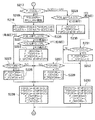
図1はこの発明の第1実施形態のパラレルハイブリッド車両を示し、エンジンE、モータM、トランスミッションTを直列に直結した構造のものである。エンジンE及びモータMの両方の駆動力は、CVTなどのトランスミッションT(マニュアルトランスミッションでもよい)を介して駆動輪たる前輪Wfに伝達される。また、ハイブリッド車両の減速時に前輪Wf側からモータM側に駆動力が伝達されると、モータMは発電機として機能していわゆる回生制動力を発生し、車体の運動エネルギーを電気エネルギーとして回収する。尚、図1においては、説明の都合上マニュアルミッション車及びCVT車の双方について関連する部品を合わせて記載する。
【0014】
モータMの駆動及び回生作動は、モータECU1のモータCPU1Mからの制御指令を受けてパワードライブユニット(PDU)2により行われる。パワードライブユニット2にはモータMと電気エネルギーの授受を行う高圧系のニッケル−水素バッテリ3が接続され、バッテリ3は、例えば、複数のセルを直列に接続したモジュールを1単位として更に複数個のモジュールを直列に接続したものである。ハイブリッド車両には各種補機類を駆動するための12ボルトの補助バッテリ4が搭載され、この補助バッテリ4はバッテリ3にDC−DCコンバータであるダウンバータ5を介して接続される。FIECU11により制御されるダウンバータ5は、バッテリ3の電圧を降圧して補助バッテリ4を充電する。尚、モータECU1は、バッテリ3を保護すると共にその残容量を算出するバッテリCPU1Bを備えている。また、前記CVTであるトランスミッションTにはこれを制御するCVTECU21が接続されている。
【0015】
FIECU11は、前記モータECU1及び前記ダウンバータ5に加えて、エンジンEへの燃料供給量を調整する図示しない燃料噴射弁、スタータモータの作動の他、点火時期等の制御を行う。そのためFIECU11には、車速VPを検出する車速センサS1からの信号と、エンジン回転数NEを検出するエンジン回転数センサS2からの信号と、トランスミッションTのシフトポジションを検出するシフトポジションセンサS3からの信号と、ブレーキペダル8の操作を検出するブレーキスイッチS4からの信号と、クラッチペダル9の操作を検出するクラッチスイッチS5からの信号と、スロットル弁32のスロットル開度THを検出するスロットル開度センサS6からの信号と、吸気管負圧を検出する吸気管負圧センサ(吸気管負圧検出手段)S7からの信号と、ノックセンサS8からの信号等が入力される。
【0016】
BSはブレーキペダルに連係された倍力装置を示し、この倍力装置BSにはブレーキマスターパワー内負圧(以下マスターパワー内負圧という)を検出するマスターパワー内負圧センサS9が設けられ、このマスターパワー内負圧センサS9はFIECU11に接続されている。
尚、吸気管負圧センサS7とスロットル開度センサS6は吸気通路30に設けられ、マスターパワー内負圧センサS9は吸気通路30に接続された連通路31に設けられている。
【0017】
ここで、吸気通路30には、スロットル弁32の上流側と下流側とを結ぶ2次エアー通路33が設けられ、この2次エアー通路33にはこれを開閉する制御バルブ34が設けられている。2次エアー通路33はスロットル弁32の全閉時においても少量の空気をシリンダ内に供給するためのものである。そして、制御バルブ34は吸気管負圧センサS7により検出された吸気管負圧に応じてFIECU11からの信号により開閉作動されるものである。また、後述するPOILセンサ(油圧検出手段)S10、スプールバルブ(アクチュエータ)71のソレノイド、TOILセンサS11もFIECU11に接続されている。
【0018】
エンジンEは吸気側と排気側とに減速休筒運転のための可変バルブタイミング機構(気筒休止機構)VTを備えた3つの気筒と、減速休筒運転を行わない通常の動弁機構NTを備えた1つの気筒を有している。
つまり、上記エンジンEは、休止可能な3つの気筒を含む4つの気筒を稼働する通常運転と、前記3つの気筒を休止する減速休筒運転とに切替自在な休筒エンジンであり、休止可能な気筒の吸気弁IVと排気弁EVが、可変バルブタイミング機構VTにより運転の休止をできる構造となっている。
【0019】
具体的に可変バルブタイミング機構VTを図2〜図4によって説明する。
図2は、SOHC型のエンジンに減速休筒運転のための可変バルブタイミング機構VTを適用した一例を示す。図示しないシリンダには吸気弁IVと排気弁EVが設けられ、これら吸気弁IVと排気弁EVは弁スプリング51,51により図示しない吸気、排気ポートを閉じる方向に付勢されている。一方、52はカムシャフト53に設けられたリフトカムであり、このリフトカム52には、ロッカーアームシャフト62を介して回動可能に支持された吸気弁側、排気弁側カムリフト用ロッカーアーム54a,54bが連係している。
【0020】
また、ロッカーアームシャフト62にはカムリフト用ロッカーアーム54a,54bに隣接して弁駆動用ロッカーアーム55a,55bが回動可能に支持されている。そして、弁駆動用ロッカーアーム55a,55bの回動端が前記吸気弁IV、排気弁EVの上端を押圧して吸気弁IV、排気弁EVを開弁作動させるようになっている。また、図3に示すように弁駆動用ロッカーアーム55a,55bの基端側(弁当接部分とは反対側)はカムシャフト53に設けられた真円カム531に摺接可能に構成されている。
【0021】
図3は、排気弁側を例にして、前記カムリフト用ロッカーアーム54bと弁駆動用ロッカーアーム55bを示したものである。
図3a)、図3(b)において、カムリフト用ロッカーアーム54bと弁駆動用ロッカーアーム55bには、ロッカーアームシャフト62を中心にしてリフトカム52と反対側に、カムリフト用ロッカーアーム54bと弁駆動用ロッカーアーム55bとに渡る油圧室56が形成されている。油圧室56内にはピン(スライド部材)57a、解除ピン(スライド部材)57bがスライド自在に設けられ、ピン57aは、ピンスプリング58を介してカムリフト用ロッカーアーム54b側に付勢されている。
【0022】
ロッカーアームシャフト62の内部には仕切部Sを介して油圧通路59(59a、59b)が区画形成されている。油圧通路(休筒側経路)59bは、油圧通路59bの開口部60、カムリフト用ロッカーアーム54bの連通路(休筒側経路)61を介して、解除ピン57b側の油圧室56に連通し、油圧通路(休筒解除側経路)59aは、油圧通路59aの開口部60、弁駆動用ロッカーアーム55bの連通路(休筒解除側経路)61を介して、ピン57a側の油圧室56に連通し図示しないドレン通路に接続可能にされている。
【0023】
ここで、油圧通路59bから油圧が作用しない場合は、図3(a)に示すように、前記ピン57aは、ピンスプリング58により前記カムリフト用ロッカーアーム54bと弁駆動用ロッカーアーム55bとの双方に跨る位置となり、一方、気筒休止信号により油圧通路59bから油圧が作用した場合は、図3(b)に示すように、前記ピン57aは解除ピン57bと共にピンスプリング58に抗して弁駆動用ロッカーアーム55b側にスライドして、ピン57aは解除ピン57bとの境界部分が前記カムリフト用ロッカーアーム54bと弁駆動用ロッカーアーム55bとの境界部分に一致して両者の連結を解除する。尚、吸気弁側も同様の構成である。ここで、前記油圧通路59a,59bは可変バルブタイミング機構VTの油圧を確保するスプールバルブ71を介してオイルポンプ70に接続されている。
【0024】
そして、図4に示すように、スプールバルブ71の気筒休止側通路(休筒側経路)72は前記ロッカーアームシャフト62の油圧通路59bに接続され、スプールバルブ71の気筒休止解除側通路(休筒解除側経路)73は前記油圧通路59aに接続されている。ここで、気筒休止解除側通路73にはPOILセンサS10が接続されている。POILセンサS10は、気筒休止時においては低圧となり、通常運転時には高圧となる気筒休止解除側通路73の油圧を監視している。また、オイルポンプ70の吐出側通路であってスプールバルブ71への通路から分岐してエンジンEに作動油を供給する供給通路74には油温を検出する前記TOILセンサS11(図1に示す)が接続され、供給される作動油の温度を監視している。
【0025】
したがって、後述する減速休筒運転の条件が満足されると、FIECU11からの信号によりスプールバルブ71が作動し、オイルポンプ70を介して、吸気弁側及び排気弁側の双方で前記油圧通路59bから油圧室56に油圧が作用する。すると、それまでカムリフト用ロッカーアーム54a,54bと弁駆動用ロッカーアーム55a,55bとを一体にしていたピン57a,57a、解除ピン57b,57bは弁駆動用ロッカーアーム55a,55b側へスライドし、カムリフト用ロッカーアーム54a,54bと弁駆動用ロッカーアーム55a,55bとの連結が解除される。
【0026】
よって、リフトカム52の回転運動によりカムリフト用ロッカーアーム54a,54bは駆動するが、ピン57a、解除ピン57bによるカムリフト用ロッカーアーム54a,54bとの連結が解除された弁駆動用ロッカーアーム55a,55bにはその動きは伝達されない。これにより、吸気弁側、排気弁側の弁駆動用ロッカーアーム55a,55bは駆動しないため、各弁IV、EVは閉じたままとなり、減速休筒運転を可能としている。
【0027】
「減速休筒運転切替実行処理」
次に、図5に基づいて、減速休筒運転切替実行処理を説明する。
ここで減速休筒運転とは、一定の条件で減速回生時に前記可変バルブタイミング機構VTにより吸気弁、排気弁を閉鎖する運転を意味し、エンジンフリクションを低減させ減速回生量を増加させるために行われる。以下に示すフローチャートでは、この減速休筒運転と、気筒休止を行わない全気筒運転(通常運転)とを切り替えるためのフラグ(気筒休止実施フラグF_DECCS)のセット・リセットを所定周期で行っている。
【0028】
ステップS100において減速G過大時休筒解除要求フラグF_GDECCSが「1」か否かを判定する。判定結果が「YES」である場合はステップS111に進み、判定結果が「NO」である場合はステップS101に進む。
ステップS101においては、減速G過大時減速回生解除要求フラグF_GDECMAが「1」か否かを判定する。判定結果が「YES」である場合はステップS111に進み、判定結果が「NO」である場合はステップS102に進む。
【0029】
ステップS100の判別が設けられているのは、車両を停止することが最優先されている場合には、気筒休止を行わない方が好ましいからである。また、急減速Gのブレーキングはマスターパワー内負圧を大きく低下させ、その後気筒休止途中において通常運転に復帰してしまう可能性が大きいため、予めこのような高減速Gのブレーキングがなされた場合には気筒休止を解除するものである。
また、ステップS101の判別が設けられているのは、急減速時において回生による車輪スリップを防止するためにも気筒休止を行わない方が好ましいからである。
【0030】
ステップS102においては、後述する減速休筒実施条件判断処理がなされ、ステップS103に進む。
ステップS103においては、減速休筒条件成立フラグF_DCSCNDが「1」か否かを判定する。判定結果が「NO」(気筒休止実施条件不成立)である場合はステップS111に進み、判定結果が「YES」(気筒休止実施条件成立)である場合はステップS104に進む。
ステップS104において、後述するソレノイドONディレータイマTDCSDL1が「0」か否かを判定する。判定結果が「YES」の場合は、一定の時間が経過しているのでステップS105に進む。ステップS104における判定結果が「NO」の場合は、一定の時間が経過していないのでステップS113に進む。
【0031】
ステップS105において、前記スプールバルブ71用のソレノイドOFFディレータイマTDCSDL2に所定値#TMDCS2をセットしてステップS106に進む。減速休筒運転から通常運転に移行する場合に、ステップS103の判定が終了してから前記スプールバルブ71のソレノイドのOFF作動を完了させるまでの間に一定の時間を確保するためである。
【0032】
ステップS106では気筒休止用ソレノイドフラグF_CSSOLに「1」をセットし(スプールバルブ71の気筒休止用ソレノイドをON)ステップS107に進む。このフラグはスプールバルブ71の気筒休止用ソレノイドをONとなると「1」となり、OFFとなると「0」となるフラグである。
ステップS107において、気筒休止のための前記ソレノイドのON作動により、油圧が実際に発生しているか否かをPOILセンサS10により判定する。具体的にはエンジン油圧POILが気筒休止運転実行判定油圧#POILCSH以下であるか否かを判定する。判定結果が「YES」である場合は、ステップS108に進む。判定結果が「NO」(ヒステリシスがある)で高圧側である場合は、ステップS115に進む。尚、POILセンサS10に代えて油圧スイッチを用いて判定することも可能である。
【0033】
ステップS108において、スプールバルブ71がON作動してから油圧が印加されるまでの時間を確保するために気筒休止運転実行ディレータイマTCSDLY1が「0」か否かを判定する。判定結果が「YES」の場合はステップS109に進む。判定結果が「NO」である場合はステップS117に進む。
ステップS109において、エンジン回転数NEに応じてタイマ値#TMNCSDL2をテーブル検索し、気筒休止運転解除ディレータイマTCSDLY2をセットする。エンジン回転数NEに応じてタイマ値を設定したのは、油圧の変化応答性時間がエンジン回転数NEにより変化するためである。よってタイマ値#TMNCSDL2はエンジン回転数NEが低いほど大きくなる値となっている。
そして、ステップS110において気筒休止実施フラグF_DECCSに「1」(減速休筒実施中)をセットし制御を終了する。
【0034】
ステップS111において、ソレノイドOFFディレータイマTDCSDL2が「0」か否かを判定する。判定結果が「YES」の場合は、一定の時間が経過しているのでステップS112に進む。ステップS111における判定結果が「NO」の場合は、一定の時間が経過していないのでステップS106に進む。
ステップS112において、スプールバルブ71のソレノイドONディレータイマTDCSDL1に所定値#TMDCS1をセットしてステップS113に進む。通常運転から減速休筒運転に移行する場合に、ステップS103の判定が終了してからステップS106のスプールバルブ71のソレノイドをON作動させるまでの間に一定の時間を確保するためである。
【0035】
ステップS113では気筒休止用ソレノイドフラグF_CSSOLに「0」をセットし(スプールバルブ71の気筒休止用ソレノイドをOFF)ステップS114に進む。
ステップS114において、気筒休止解除のための前記ソレノイドのOFF作動により、油圧が実際に解除されているか否かをPOILセンサS10により判定する。具体的には油圧POILが気筒休止運転解除判定油圧#POILCSL以上であるか否かを判定する。判定結果が「YES」で高圧側(ヒステリシス付き)である場合は、ステップS115に進む。判定結果が「NO」である場合は、ステップS108に進む。この場合もPOILセンサS10に代えて油圧スイッチを使用することができる。
【0036】
ステップS115において、スプールバルブ71がOFF作動してから油圧が解除されるまでの時間を確保するために気筒休止運転解除ディレータイマTCSDLY2が「0」か否かを判定する。判定結果が「YES」の場合はステップS116に進む。判定結果が「NO」である場合はステップS110に進む。
ステップS116において、エンジン回転数NEに応じてタイマ値#TMNCSDL1をテーブル検索し、気筒休止運転実行ディレータイマTCSDLY1をセットしてステップS117に進む。ここにおいてもエンジン回転数NEに応じてタイマ値を設定したのは、油圧の変化応答性時間がエンジン回転数NEにより変化するためである。よって、タイマ値#TMNCSDL1はエンジン回転数NEが低いほど大きくなる値となっている。
【0037】
ステップS117において、気筒休止運転強制解除タイマTCSCENDにタイマ値#TMCSCENDをセットして、ステップS118に進む。ここで、この気筒休止運転強制解除タイマTCSCENDは、気筒休止が行われてから一定の時間が経過すると、強制的に気筒休止が解除されるタイマである。
そして、ステップS118において気筒休止実施フラグF_DECCSに「0」(通常運転実施中)をセットし制御を終了する。
【0038】
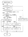
「減速休筒実施条件判断処理」
次に、図6〜図8に基づいて、図5のステップS102における減速休筒実施条件判断処理を説明する。この処理は、減速休筒条件を満たすか否かを常時監視し減速休筒条件成立フラグF_DCSCNDをセット、リセットするものである。尚、この処理は所定周期で繰り返される。
ステップS151において、気筒休止強制解除タイマTCSCENDが「0」か否かを判定する。判定結果が「YES」である場合は図8のステップS184に進み、判定結果が「NO」である場合はステップS152に進む。気筒休止強制解除タイマTCSCENDが「0」となった場合は、気筒休止を解除する必要があるからである。
【0039】
ステップS152において、燃料カットフラグF_FCが「1」か否かを判定する。ステップS152の判定結果が「YES」である場合はステップS153に進み、判定結果が「NO」である場合はステップS166に進む。この判定があるのは、気筒休止は、減速燃料カット時におけるエンジンのフリクションを低減してその低減分の回生量を増量することを目的としているからである。
ステップS166においては、気筒休止終了フラグF_DCSCENDに「0」をセットして図8のステップS184に進む。
【0040】
ステップS153においては、気筒休止終了フラグF_DCSCENDが「1」か否かを判定する。判定結果が「YES」である場合は図8のステップS184に進み、判定結果が「NO」である場合はステップS154に進む。
ステップS154において、外気温TAが所定の範囲内(気筒休止実施下限外気温#TADCSL≦TA≦気筒休止実施上限外気温#TADCSH)にあるか否かを判定する。ステップS154における判定の結果、外気温TAが所定の範囲内にあると判定された場合はステップS155に進む。外気温TAが所定の範囲から外れている場合は図8のステップS184に進む。外気温TAが気筒休止実施下限外気温#TADCSLを下回ったり、気筒休止実施上限外気温#TADCSHを上回っている場合には、気筒休止を行うとエンジンが不安定となるからである。
【0041】
ステップS155では、冷却水温TWが所定の範囲内(気筒休止実施下限冷却水温#TWDCSL≦TW≦気筒休止実施上限冷却水温#TWDCSH)にあるか否かを判定する。ステップS155における判定の結果、冷却水温TWが所定の範囲内にあると判定された場合はステップS156に進む。所定の範囲から外れている場合は図8のステップS184に進む。冷却水温TWが気筒休止実施下限冷却水温#TWDCSLを下回ったり、気筒休止実施上限冷却水温#TWDCSHを上回っている場合には、気筒休止を行うとエンジンが不安定となるからである。
【0042】
ステップS156において、大気圧PAが気筒休止実施上限大気圧#PADCS以上であるか否かを判定する。ステップS156の判定結果が「YES」(高気圧)である場合はステップS157に進み、判定結果が「NO」である場合は図8のステップS184に進む。大気圧が低い場合に気筒休止を行うのは好ましくないからである(例えば、ブレーキのマスターパワー内負圧をブレーキ作動時に十分な状態で確保できていない可能性もあるため)。
【0043】
ステップS157において、12ボルトの補助バッテリ4の電圧VBが気筒休止実施上限電圧#VBDCS以上であるか否かを判定する。判定結果が「YES」(電圧大)である場合はステップS159に進み、判定結果が「NO」である場合は図8のステップS184に進む。12ボルトの補助バッテリ4の電圧VBが所定値より小さい場合には、スプールバルブ71の応答性が悪くなるからである。また、低温環境下のバッテリ電圧低下やバッテリ劣化時における対策のためである。
【0044】
ステップS159において、IDLE判定フラグF_THIDLMGが「1」か否かを判定する。判定結果が「YES」(全閉ではない)である場合は図8のステップS184に進み、判定結果が「NO」(全閉状態)である場合はステップS160に進む。スロットル全閉状態からスロットルが少しでも開いた場合には気筒休止の継続を解除して商品性を高めるためである。
【0045】
ステップS160では、油温TOIL(エンジンオイル温度)が所定の範囲内(気筒休止実施下限油温#TODCSL≦TOIL≦気筒休止実施上限油温#TODCSH)にあるか否かを判定する。ステップS160における判定の結果、油温TOILが所定の範囲内にあると判定された場合はステップS161に進む。所定の範囲から外れている場合は図8のステップS184に進む。油温TOILが気筒休止実施下限油温#TODCSLを下回ったり、気筒休止実施上限油温#TODCSHを上回っている場合に気筒休止を行うとエンジン作動時と気筒休止時の切り替えの応答性が安定しないからである。
【0046】
ステップS161において、減速回生中か否かを判定する。判定結果が「YES」である場合はステップS162に進み、判定結果が「NO」である場合は図8のステップS184に進む。気筒休止は、減速回生時におけるエンジンのフリクションを低減してその低減分の回生量を増量することを目的としているからである。
ステップS162において、MT/CVT判定フラグF_ATが「1」か否かを判定する。判定結果が「NO」(MT車)である場合はステップS163に進む。判定結果が「YES」(AT/CVT車)である場合はステップS167に進む。
【0047】
ステップS167において、インギア判定フラグF_ATNPが「1」か否かを判定する。判定結果が「NO」(インギア)である場合はステップS168に進む。判定結果が「YES」(N/Pレンジ)である場合は図8のステップS184に進む。
ステップS168において、リバースポジション判定フラグF_ATPRが「1」か否かを判定する。判定結果が「YES」(リバースポジション)である場合は図8のステップS184に進む。判定結果が「NO」(リバースポジション以外)である場合はステップS165に進む。
これらステップS167、ステップS168の処理によりN/Pレンジ、リバースポジションでの気筒休止は解除される。
【0048】
ステップS163において、前回ギア位置NGRが気筒休止継続下限ギア位置#NGRDCS(例えば、3速でこの位置を含む)よりHiギア側か否かを判定する。判定結果が「YES」(Hiギア側)である場合はステップS164に進み、判定結果が「NO」(Loギア側)である場合は図8のステップS184に進む。これは、低速ギアでは回生率の低下や、渋滞状態等で頻繁に気筒休止の切り替えが行われることを防止するためである。
【0049】
ステップS164において、半クラッチ判断フラグF_NGRHCLが「1」(半クラッチ)か否かを判定する。判定結果が「YES」である場合(半クラッチ)は図8のステップS184に進み、判定結果が「NO」である場合はステップS165に進む。よって、例えば、車両停止のために半クラッチになった場合におけるエンジンストールや、加速時にギアチェンジのために半クラッチ状態になった場合に運転者の加速要求に対応できないような不具合が起きる不要な気筒休止を防止できる。
【0050】
ステップS165において、エンジン回転数の変化率DNEが気筒休止継続実行上限エンジン回転数変化率#DNEDCS以下か否かを判定する。判定結果が「YES」(エンジン回転数の低下率が大きい)である場合は図8のステップS184に進み、判定結果が「NO」である場合はステップS169に進む。エンジン回転数の低下率が大きい場合に気筒休止を行った場合のエンジンストールを防止するためである。
【0051】
図7のステップS169において、バッテリ3のバッテリ温度TBATが所定の範囲内(気筒休止下限バッテリ温度#TBDCSL≦TBAT≦気筒休止上限バッテリ温度#TBDCSH)であるか否かを判定する。判定結果が「YES」である場合はステップS170に進み、判定結果が「NO」である場合は図8のステップS184に進む。バッテリ3の温度が一定の範囲内にない場合は気筒休止を行うべきでないからである。
【0052】
ステップS170において、バッテリ残容量QBATが所定の範囲内(気筒休止継続実行下限残容量#QBDCSL≦QBAT≦気筒休止継続実行上限残容量#QBDCSH)にあるか否かを判定する。ステップS170における判定の結果、バッテリ残容量QBATが所定の範囲内にあると判定された場合はステップS170Aに進む。バッテリ残容量QBATが所定の範囲から外れている場合は図8のステップS184に進む。バッテリ残容量QBATが気筒休止継続実行下限残容量#QBDCSLを下回ったり、気筒休止継続実行上限残容量#QBDCSHを上回っている場合には気筒休止は解除される。バッテリ残容量QBATが少な過ぎると気筒休止から復帰する場合に行われるモータMによるエンジン駆動補助のためのエネルギーが確保できないからである。また、バッテリ残容量QBATが多過ぎると回生を取れないからである。
【0053】
ステップS170Aにおいて、車速VPが気筒休止継続実行上限車速#VPDCSH以下か否かを判定する。判定結果が「YES」である場合はステップS170Bに進み、判定結果が「NO」である場合(ヒステリシス付き)は図8のステップS184に進む。
ステップS170BにおいてブレーキスイッチフラグF_BKSWが「1」か否かを判定する。判定結果が「YES」(ブレーキを踏んでいる)である場合はステップS170Dに進み、判定結果が「NO」(ブレーキを踏んでいない)である場合はステップS170Cに進む。尚、ブレーキスイッチフラグF_BKSWに替えて、ブレーキ油圧、車両の減速状態(減速G)を検出してブレーキが踏み込まれたと判定するようにしてもよい。
【0054】
ステップS170Cにおいて、車速VPが気筒休止継続実行下限ブレーキOFF時車速#VPDCSL(例えば、30km/h)以上か否かを判定する。判定結果が「YES」である場合は図8のステップS171に進み、判定結果が「NO」である場合(ヒステリシス付き)は図8のステップS184に進む。
ステップS170Dにおいて、車速VPが気筒休止継続実行下限ブレーキングON時車速#VPDCSBL(例えば、10km/h)以上か否かを判定する。判定結果が「YES」である場合は図8のステップS171に進み、判定結果が「NO」である場合(ヒステリシス付き)は図8のステップS184に進む。
【0055】
このようにブレーキON時とブレーキOFF時で気筒休止継続実行下限車速を変更したのは、ブレーキONの際には運転者に車両停止の意思がある可能性が高く、ブレーキOFFの際には運転者に再加速の意思がある可能性があるからである。したがって、気筒休止継続実行下限ブレーキングON時車速#VPDCSBLよりも気筒休止継続実行下限ブレーキOFF時車速#VPDCSLを高く設定して、ブレーキON時の方がブレーキOFF時よりも気筒休止に入りやすいようにすると共に、再加速時における運転者の加速意思に対してスムーズに対応しドライバビリティを向上するようにしている。上記気筒休止継続実行下限ブレーキOFF時車速#VPDCSLと気筒休止継続実行下限ブレーキングON時車速#VPDCSBLとが、基準下限車速を構成している。
【0056】
ステップS171において、エンジン回転数NEが所定値以下(NE≦気筒休止継続実行上限エンジン回転数#NDCSH)であるか否かを判定する。ステップS171における判定の結果、エンジン回転数NEが所定値以下であると判定された場合はステップS172に進む。エンジン回転数NEが所定値を越える場合(ヒステリシス付き)はステップS184に進む。エンジン回転数NEが高過ぎると高回転で油圧が高くなり過ぎ気筒休止の切り替えができなくなる可能性があり、また、気筒休止用作動油の消費悪化の可能性があるからである。
【0057】
ステップS172において、油温TOILに応じて#NDCSHテーブル検索により気筒休止継続実行下限エンジン回転数NDCSL(基準エンジン回転数)を求めてステップS173に進む。このように油温TOILに応じて気筒休止継続実行下限エンジン回転数#NDCSLを検索するのは、エンジンオイル温度である油温が上がれば上がるほど粘度が下がり圧力をかけ難くなるから、早めに、つまりエンジン回転数NEが下がらないうちに気筒休止から復帰する必要があるからである。これにより油温TOILつまり、エンジンの熱的状況に応じて、精度の高い制御を行うことができる。ここで、気筒休止継続実行下限エンジン回転数#NDCSLはヒステリシスを持った値であり、油温TOILに応じて高くなる値である。
尚、上記油温TOILに替えて、エンジン水温やエンジン自体の温度に基づいて気筒休止継続実行下限エンジン回転数#NDCSLを設定してもよい。
【0058】
ステップS173においてはブレーキスイッチフラグF_BKSWが「1」か否かを判定する。判定結果が「YES」(ブレーキを踏んでいる)である場合はステップS174に進み、判定結果が「NO」(ブレーキを踏んでいない)である場合はステップS182に進む。尚、前述したようにブレーキスイッチフラグF_BKSWに替えて、ブレーキ油圧、車両の減速状態(減速G)を検出してブレーキが踏み込まれたと判定するようにしてもよい。
【0059】
ステップS182においては、気筒休止継続実行下限エンジン回転数NDCSLを所定値#DNDCSLだけ引き上げてステップS174に進む。このようにブレーキ作動の有無を検出して運転者の車両停止の意思をある程度把握し、気筒休止継続実行下限エンジン回転数NDCSLを所定値#DNDCSLだけ引き上げることで、ブレーキON時の方がブレーキOFF時よりも気筒休止に入りやすいようにすると共に、再加速時における運転者の加速意思に対してスムーズに対応しドライバビリティを向上することができる。
尚、気筒休止継続実行下限エンジン回転数NDCSLを変更することができれば、気筒休止継続実行下限エンジン回転数NDCSLを所定値#DNDCSLだけ引き上げる代わりに、気筒休止継続実行下限エンジン回転数NDCSLに係数を乗じて補正したり、マップとして別持ちにしたりするなど様々な態様が採用可能である。
【0060】
ステップS174ではエンジン回転数NEが気筒休止継続実行下限エンジン回転数NDCSL以上か否かを判定する。判定結果が「YES」である場合はステップS175に進む、判定結果が「NO」である場合はステップS184に進む。
ステップS175においては、気筒休止スタンバイフラグF_DCSSTBが「1」か否かを判定する。このフラグは気筒休止前条件が成立するとステップS178で「1」がセットされ、気筒休止前条件が成立しないとステップS185で「0」がセットされるフラグである。判定結果が「YES」である場合はステップS178に進み、判定結果が「NO」である場合はステップS176に進む。
【0061】
ステップS176において、吸気管負圧PBGAがエンジン回転数NEに応じて定められたテーブル検索値(エンジン回転数の上昇と共に小さく(負圧が大きく)なる値)である気筒休止実施上限負圧#PBGDCS以上であるか否かを判定する。
エンジン負荷が高い場合(吸気管負圧が気筒休止実施上限負圧#PBGDCSより小さい場合)はすぐに気筒休止を行わないで、マスターパワー内負圧を確保するためにこの吸気管負圧を使用してから気筒休止を行うためである。ステップS176の判定結果が「YES」(低負荷)である場合はステップS177に進み、判定結果が「NO」(高負荷)である場合はステップS183に進む。ステップS183においては、減速吸気管負圧上昇フラグF_DECPBUPに「1」をセットしてステップS185に進む。ここで、上記減速吸気管負圧上昇フラグF_DECPBUPのフラグ値が「1」の場合は、一定の条件で2次エアー通路33は閉鎖され、フラグ値が「0」の場合は、一定の条件で2次エアー通路33は開放される。
【0062】
つまり、ステップS176において高負荷であると判定された場合は、負圧が小さいので2次エアー通路33を閉鎖し(ステップS183)、気筒休止には入らず(ステップS188)、ステップS176において吸気管負圧PBGAが所定値となった場合に、これをトリガとしてステップS177からステップS180へと移行し気筒休止条件成立(減速休筒条件成立フラグF_DCSCND=1)とするのである。
ステップS177においては、減速吸気管負圧上昇フラグF_DECPBUPに「0」をセットしてステップS178に進む。ステップS178においては、気筒休止前条件が成立するため、気筒休止スタンバイフラグF_DCSSTBに「1」をセットしてステップS179に進む。
【0063】
ステップS179では、マスターパワー内負圧MPGAが気筒休止実施継続実行上限負圧#MPDCS以上か否かを判定する。ここで、気筒休止実施継続実行上限負圧#MPDCSは車速VPに応じて設定されたテーブル検索値(車速の上昇と共に小さく(負圧が大きく)なる値)である。マスターパワー内負圧MPGAは、車両を停止させるためのものであることを考慮すると車両の運動エネルギー、つまり車速VPに応じて設定するのが好ましいからである。
【0064】
ステップS179における判定の結果、マスターパワー内負圧MPGAが気筒休止継続実行上限負圧#MPDCS以上である場合(マスターパワー内負圧大)はステップS180に進む。ステップS179における判定の結果、マスターパワー内負圧MPGAが気筒休止継続実行上限負圧#MPDCSより小さい場合(マスターパワー内負圧小)はステップS186に進む。マスターパワー内負圧MPGAが十分に得られない場合に気筒休止を継続することは好ましくないからである。
ステップS180では、減速休筒条件成立フラグF_DCSCNDに「1」をセットして制御を終了する。
【0065】
ステップS184においては、減速吸気管負圧上昇フラグF_DECPBUPに「0」をセットしてステップS185に進む。
ステップS185においては、気筒休止前条件が不成立となるため、気筒休止スタンバイフラグF_DCSSTBに「0」をセットしてステップS186に進む。
ステップS186では、この処理で決定される減速休筒条件成立フラグF_DCSCNDが「1」か否かを判定する。判定結果が「YES」である場合はステップS187に進み、判定結果が「NO」である場合はステップS188に進む。
ステップS187では気筒休止終了フラグF_DCSCENDに「1」をセットしてステップS188に進む。
ステップS188では、減速休筒条件成立フラグF_DCSCNDに「0」をセットして制御を終了する。
【0066】
「POILセンサ故障判定」
次に、図9、図10のフローチャートに基づいてPOILセンサ故障判定を説明する。この判定はPOILセンサS10の出力を常時監視することにより主としてPOILセンサS10の故障を検出するものである。具体的にはPOILセンサS10の故障検出をエンジンストール時、アイドル停止時、減速休筒時、通常走行時に分けて判定し、故障フラグF_FSPOANYに、故障の場合には「1」を正常の場合には「0」をセットするようになっている。尚、この処理は所定周期で繰り返される。ここでアイドル停止は一定の条件でエンジンを停止し、条件を満たさなくなるとエンジンが始動するモードである。
【0067】
ステップS201において、TOILセンサ故障フラグF_FSTOANYが「1」か否かを判定する。判定結果が「YES」で、TOILセンサS11が故障している場合はステップS211に進み、判定結果が「NO」で、TOILセンサS11が正常である場合はステップS202に進む。
ステップS211ではPOILセンサ故障フラグに「0」をセットして処理を終了する。TOILセンサS11が故障している場合は、POILセンサS10の故障判定を行わないためである。
ステップS202では、エンジンストールフラグF_MEOFが「1」か否かを判定する。判定結果が「YES」でエンジンストール中の場合はステップS203に進み、判定結果が「NO」で、始動中である場合はステップS217に進む。
【0068】
ステップS203において、アイドル停止フラグF_IDLSTPが「1」か否かを判定する。ステップS203における判定結果が「YES」で、アイドル停止中である場合はステップS212に進み、判定結果が「NO」で、アイドル停止中でない場合はステップS204に進む。
ステップS204では、POILセンサの出力値POILがエンジンストール時閾値#POJUDES以上か否かを判定する。判定結果が「YES」で高油圧の場合はステップS206に進み、判定結果が「NO」で低油圧の場合はステップS205に進む。
ステップS205では、エンジンストール時油圧正常フラグF_OKPOESに「1」をセットし、エンジンストール時油圧異常フラグF_FSDPOESに「0」をセットし、更に、エンジンストール時故障検知確認タイマTFSPOESに所定値#TMFSPOESをセットしてステップS208に進む。
【0069】
ここで、エンジンストール時に検出油圧が正常であれば、エンジンストール時油圧正常フラグF_OKPOESは「1」、エンジンストール時油圧異常フラグF_FSDPOESが「0」となり、油圧が異常であればエンジンストール時油圧正常フラグF_OKPOESは「0」、エンジンストール時油圧異常フラグF_FSDPOESは「1」となる。
【0070】
ステップS206では、エンジンストール時故障検知確認タイマTFSPOESが「0」か否かを判定する。判定結果が「YES」である場合はステップS207に進み、判定結果が「NO」である場合はステップS208に進む。
ステップS207では、エンジンストール時油圧異常フラグF_FSDPOESに「1」をセットし、エンジンストール時油圧正常フラグF_OKPOESに「0」をセットしステップS208に進む。
ここで、上記エンジンストール時故障検知確認タイマTFSPOESにより、ステップS204で「YES」、つまり油圧が高いとの判定が一定時間継続した場合に異常判定がなされる。
【0071】
ステップS208では、アイドル停止時故障検知確認タイマTFSPOISに所定値#TMFSPOISをセットし、通常時故障検知確認タイマTFSPORNに所定値#TMFSPORNをセットし、休筒時故障検知確認タイマTFSPOCSに所定値#TMFSPOCSをセットし、アイドル停止時油圧正常フラグF_OKPOISに「0」をセットし、通常時油圧正常フラグF_OKPORNに「0」をセットし、休筒時油圧正常フラグF_OKPOCSに「0」をセットしてステップS209に進む。
ここで、アイドル停止時油圧正常フラグF_OKPOISはアイドル停止時において検出油圧が正常であれば「1」、異常であれば「0」がセットされるフラグである。また、通常時油圧正常フラグF_OKPORNは、通常運転時において検出油圧が正常であれば「1」、異常であれば「0」がセットされるフラグである。そして、休筒時油圧正常フラグF_OKPOCSは休筒時において検出油圧が正常であれば「1」、異常であれば「0」がセットされるフラグである。
【0072】
ステップS209では、エンジンストール時油圧異常フラグF_FSDPOES、アイドル停止時油圧異常フラグF_FSDPOIS、通常時高圧側油圧異常フラグF_FSDPORH、通常時低圧側油圧異常フラグF_FSDPORL、休筒時油圧異常フラグF_FSDPOCSのいずれかが「1」であるか否かを判定する。判定結果が「YES」である場合はステップS210に進み、判定結果が「NO」である場合はステップS211に進む。
【0073】
ここで、アイドル停止時油圧異常フラグF_FSDPOISはアイドル停止時において検出油圧が異常であれば「1」、正常であれば「0」がセットされるフラグである。通常時高圧側油圧異常フラグF_FSDPORHは、通常運転時において検出油圧が高圧側で異常(上限閾値を越える)であれば「1」、正常であれば「0」がセットされるフラグである。通常時低圧側油圧異常フラグF_FSDPORLは、通常運転時において検出油圧が低圧側で異常(下限閾値を下回る)であれば「1」、正常であれば「0」がセットされるフラグである。休筒時油圧異常フラグF_FSDPOCSは休筒時において検出油圧が異常であれば「1」、正常であれば「0」がセットされるフラグである。
【0074】
ステップS210では、いずれかの場合でPOILセンサS10が故障しているので、故障フラグF_FSPOANYに「1」をセットして処理を終了する。
ステップS211では、いずれの場合もPOILセンサS10に故障は見られないため故障フラグF_FSPOANYに「0」をセットして処理を終了する。
【0075】
ステップS212においては、POILセンサの出力値POILがアイドル停止時閾値#POJUDIS以上か否かを判定する。判定結果が「YES」で高油圧の場合はステップS214に進み、判定結果が「NO」で低油圧の場合はステップS213に進む。
ステップS213では、アイドル停止時油圧正常フラグF_OKPOISに「1」をセットし、アイドル停止時油圧異常フラグF_FSDPOISに「0」をセットし、更に、アイドル停止時故障検知確認タイマTFSPOISに所定値#TMFSPOISをセットしてステップS216に進む。
【0076】
ステップS214では、アイドル停止時故障検知確認タイマTFSPOISが「0」か否かを判定する。判定結果が「YES」である場合はステップS215に進み、判定結果が「NO」である場合はステップS216に進む。
ステップS215では、アイドル停止時油圧異常フラグF_FSDPOISに「1」をセットし、アイドル停止時油圧正常フラグF_OKPOISに「0」をセットしステップS216に進む。
ここで、上記アイドル停止時故障検知確認タイマTFSPOISにより、ステップS212で「YES」、つまり油圧が高いとの判定が一定時間継続した場合に異常判定がなされる。
【0077】
ステップS216では、エンジンストール時故障検知確認タイマTFSPOESに所定値#TMFSPOESをセットし、通常時故障検知確認タイマTFSPORNに所定値#TMFSPORNをセットし、休筒時故障検知確認タイマTFSPOCSに所定値#TMFSPOCSをセットし、エンジンストール時油圧正常フラグF_OKPOESに「0」をセットし、通常時油圧正常フラグF_OKPORNに「0」をセットし、休筒時油圧正常フラグF_OKPOCSに「0」をセットしてステップS209に進む。
【0078】
ステップS217においては、気筒休止用ソレノイドフラグF_CSSOLが「1」か否かを判定する。判定結果が「YES」である場合はステップS229に進み、判定結果が「NO」である場合はステップS218に進む。
ステップS218では#POILマップ検索を行い、マップ値POILMAPNを求めステップS219に進む。ここで、#POILマップは、TOILセンサS11により検出された油温TOILとエンジン回転数NEとにより決定される値である。
ステップS219では、マップ値POILMAPNに故障判定用高圧側オフセット量#DPOILMHを加算して通常時上限閾値POJUDRHを算出し、マップ値POILMAPNから故障判定用低圧側オフセット量#DPOILMLを減算して通常時下限閾値POJUDRLを算出してステップS220に進む。
【0079】
したがって、通常(運転)時におけるPOILセンサS10の出力は、図13に示すようにエンジン回転数NEに応じて、一定の幅の間、つまり通常時上限閾値POJUDRHと通常時下限閾値POJUDRLとの間にある場合には正常と判定される。
【0080】
ステップS220において、POILセンサの出力値POILが通常時上限閾値#POJUDRH以上か否かを判定する。判定結果が「YES」で高油圧の場合はステップS223に進み、判定結果が「NO」で低油圧の場合はステップS221に進む。
ステップS223では、通常時故障検知確認タイマTFSPORNが「0」か否かを判定する。判定結果が「YES」である場合はステップS225に進み、判定結果が「NO」である場合はステップS226に進む。
【0081】
ステップS225では、通常時高圧側油圧異常フラグF_FSDPORHに「1」をセットし、通常時油圧正常フラグF_OKPORNに「0」をセットし、通常時低圧側油圧異常フラグF_FSDPORLに「0」をセットしてステップS226に進む。
ここで、上記通常時故障検知確認タイマTFSPORNにより、ステップS220で「YES」、つまり油圧が高いとの判定が一定時間継続した場合に異常判定がなされる。
【0082】
ステップS226では、エンジンストール時故障検知確認タイマTFSPOESに所定値#TMFSPOESをセットし、アイドル停止時故障検知確認タイマTFSPOISに所定値#TMFSPOISをセットし、休筒時故障検知確認タイマTFSPOCSに所定値#TMFSPOCSをセットし、エンジンストール時油圧正常フラグF_OKPOESに「0」をセットし、アイドル停止時油圧正常フラグF_OKPOISに「0」をセットし、休筒時油圧正常フラグF_OKPOCSに「0」をセットしてステップS209に進む。
【0083】
ステップS221では、POILセンサの出力値POILが通常時下限閾値#POJUDRL以下か否かを判定する。判定結果が「YES」で低油圧の場合はステップS227に進み、判定結果が「NO」で高油圧の場合はステップS222に進む。
ステップS222では、通常時油圧正常フラグF_OKPORNに「1」をセットし、通常時高圧側油圧異常フラグF_FSDPORHに「0」をセットし、通常時低圧側油圧異常フラグF_FSDPORLに「0」をセットし、通常時故障検知確認タイマTFSPORNに所定値#TMFSPORNをセットしてステップS226に進む。
【0084】
ステップS227では、通常時故障検知確認タイマTFSPORNが「0」か否かを判定する。判定結果が「YES」である場合はステップS228に進み、判定結果が「NO」である場合はステップS226に進む。
ステップS228では、通常時低圧側油圧異常フラグF_FSDPORLに「1」をセットし、通常時油圧正常フラグF_OKPORNに「0」をセットし、通常時高圧側油圧異常フラグF_FSDPORHに「0」をセットしてステップS226に進む。
ここで、上記通常時故障検知確認タイマTFSPORNにより、ステップS221で「YES」、つまり油圧が低いとの判定が一定時間継続した場合に異常判定がなされる。
【0085】
ステップS229では、POILセンサの出力値POILが休筒時閾値#POJUDCS以上か否かを判定する。判定結果が「YES」で高油圧の場合はステップS231に進み、判定結果が「NO」で低油圧の場合はステップS230に進む。
ステップS230では、休筒時油圧正常フラグF_OKPOCSに「1」をセットし、休筒時油圧異常フラグF_FSDPOCSに「0」をセットし、休筒時故障検知確認タイマTFSPOCSに所定値#TMFSPOCSをセットしてステップS233に進む。
【0086】
ステップS231では、休筒時故障検知確認タイマTFSPOCSが「0」か否かを判定する。判定結果が「YES」である場合はステップS232に進み、判定結果が「NO」である場合はステップS233に進む。
ステップS232では、休筒時油圧異常フラグF_FSDPOCSに「1」をセットし、休筒時油圧正常フラグF_OKPOCSに「0」をセットしてステップS233に進む。
ここで、上記休筒時故障検知確認タイマTFSPOCSにより、ステップS229で「YES」、つまり油圧が高いとの判定が一定時間継続した場合に異常判定がなされる。
【0087】
ステップS233では、エンジンストール時故障検知確認タイマTFSPOESに所定値#TMFSPOESをセットし、アイドル停止時故障検知確認タイマTFSPOISに所定値#TMFSPOISをセットし、通常時故障検知確認タイマTFSPORNに所定値#TMFSPORNをセットし、エンジンストール時油圧正常フラグF_OKPOESに「0」をセットし、アイドル停止時油圧正常フラグF_OKPOIS「0」をセットし、通常時油圧正常フラグF_OKPORNに「0」をセットしてステップS209に進む。
したがって、上述処理により故障と判定された場合には、POILセンサS10が適正な油圧を出力しないための故障であるため、POILセンサS10の故障、あるいはスプールバルブ71の作動不良故障を検出できる。
【0088】
「休筒気筒の故障判定」
次に、図11のフローチャートに基づいて休筒気筒の故障判定を説明する。この判定は減速時に気筒休止が実施できなくなる故障を検出するものである。具体的には、減速中のPOILセンサS10の出力値が正常な場合において、減速中の吸気管負圧PBが所定判定圧力よりも高負圧側になる場合である。図15に示すように、3つの気筒が休止するこの実施形態の減速休筒エンジンではエンジン回転数NE(N1=1500rpm、N2=2500rpm)に応じて発生する吸気管負圧は決定される。また、2つの気筒が休止するエンジンでは、3気筒休止の場合よりも吸気管負圧は高負圧側になり、1つの気筒が休止するエンジンでは、更に吸気管負圧は高負圧側になり、休止する気筒がないエンジンの場合は更にまた吸気管負圧は高負圧側になる。したがって、この実施形態において3つの気筒が正常に休止していない場合は、吸気管負圧PBは3気筒が休止している場合に比較して高負圧側になる。これを利用して休筒気筒の故障判定を故障気筒数を含めて行うことができる。尚、以下の処理は所定周期で繰り返される。
【0089】
図11において、ステップS301で気筒休止用ソレノイドフラグF_CSSOLが「1」か否かを判定する。判定結果が「YES」である場合はステップS302に進み、判定結果が「NO」である場合はステップS307に進む。
ステップS307では、休筒ピストン固着故障検知タイマTFSPLKAに所定値#TMFSPLKAである休筒ピストン固着判定確定時間をセットして処理を終了する。
ステップS302では、休筒時油圧正常フラグF_OKPOCSが「1」か否かを判定する。判定結果が「YES」である場合、つまり休筒時POILセンサ論理チェックがOKである場合はステップS303に進み、判定結果が「NO」である場合はステップS307に進む。
【0090】
ステップS303では吸気管負圧PBGAが#PBGJUDCS検索値(閾値)以上か否かを判定する。判定結果が「YES」、つまり故障して気筒休止が行われない気筒があり吸気管内に発生している負圧が判定値以上の高負圧側である場合はステップS304に進み、判定結果が「NO」、つまり故障している気筒がなく気筒休止により吸気管内に発生している負圧が判定値より大気圧側に近い低負圧側である場合はステップS308に進む。
ここで、上記#PBGJUDCS検索値は平地用の検索値と高地用の検索値があり、これを大気圧に応じて補間算出して求めたものである。この実施形態では、4気筒のうち3気筒が気筒休止を行っているが、気筒休止を行う気筒数によって上記#PBGJUDCS検索値を変更できることはいうまでもない。
【0091】
ステップS304では、休筒ピストン固着故障検知タイマTFSPLKAが「0」か否かを判定する。判定結果が「YES」である場合は所定時間経過しているのでステップS305に進み、判定結果が「NO」である場合は上記処理を繰り返す。
ステップS305では、休筒気筒固着検知フラグF_FSDPLKAに「1」をセットし、ステップS306で休筒気筒作動検知フラグF_OKPLKAに「0」をセットして処理を終了する。
また、ステップS308では、休筒気筒固着検知フラグF_FSDPLKAに「0」をセットし、ステップS309で休筒気筒作動検知フラグF_OKPLKAに「1」をセットして処理を終了する。
【0092】
ここで、休筒気筒固着検知フラグF_FSDPLKAは休筒気筒が固着しているときは「1」、休筒気筒が正常に作動しているときは「0」となるフラグである。また、休筒気筒作動検知フラグF_OKPLKAは、休筒気筒が正常に作動しているときは「1」となり、休筒気筒が固着しているときは「0」となるフラグである。
このように、上記休筒ピストン固着故障検知タイマTFSPLKAにより、ステップS303で「YES」、つまり固着したとの判定が一定時間継続した場合に故障の判定がなされる。
【0093】
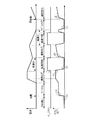
次に作用について説明する。
図12はエンジン停止状態から始動して通常走行と減速休筒を繰り返しながらアイドル停止して再始動するまでの間における、気筒休止用ソレノイドフラグF_CSSOLの状態とPOILセンサS10のチェック状態を示したものである。
エンジン停止状態では、(a)で示す位置でのPOILセンサS10の出力が低油圧(図9のステップS204)であることが確認される(図9のステップS205)。このとき、気筒休止用ソレノイドフラグF_CSSOLは「0」である。
エンジンが始動してアイドル状態になり、更に通常走行状態になると、(b)、(c)で示す位置でのPOILセンサS10の出力値がエンジン回転数NEに対応した所定圧力の範囲内(図10のステップS220、ステップS221)であることが確認される(図10のステップS222)。このとき、気筒休止用ソレノイドフラグF_CSSOLは「0」である。
【0094】
次いで、車両が減速し、減速休筒状態になると、(d)で示す位置でのPOILセンサS10の出力値が低油圧(図10のステップS229)であることが確認される(図10のステップS230)。このとき、気筒休止用ソレノイドフラグF_CSSOLは「1」である。
そして、再度通常走行状態になると前述と同様に(e)で示す位置でのPOILセンサS10の出力値が確認される(図10のステップS222)。このとき、気筒休止用ソレノイドフラグF_CSSOLは「0」である。
【0095】
更に、車両が減速し前述と同様に再度減速休筒状態になり(F_CSSOL=0)、そのままアイドル停止状態となると、(f)で示す位置でのPOILセンサS10の出力値が低油圧(図9のステップS212)であることが確認される(図9のステップS213)。このとき、気筒休止用ソレノイドフラグF_CSSOLは「0」である。
そして、再始動から通常走行に移行して上述と同様に(g)で示す位置でのPOILセンサS10の出力値が確認される(図10のステップS222)。このとき、気筒休止用ソレノイドフラグF_CSSOLは「0」である。
【0096】
ここで、POILセンサS10からの出力値がいずれかの走行状態で条件を満たさない場合、つまり(a)で示す位置において圧力が低下していない場合、あるいは、(b)、(c)、(e)、(g)で示す位置において圧力が十分に高くなっていない場合、あるいは(f)で示す位置において圧力が低下していない場合には、気筒休止用ソレノイドフラグF_CSSOLのフラグ値を加味してセンサS10の故障を検出することができる(図9のステップS209、ステップS210)。
【0097】
また、この場合にいずれかの走行状態においてPOILセンサS10の出力が異常が一定時間経過した場合に初めて故障と判別されるため(ステップS206、ステップS214、ステップS223、ステップS227、ステップS231)信頼性が高い。
【0098】
一方、図14に示すように、通常走行から減速休筒に移行し再度通常走行に移行する場合を例に説明する。通常走行から減速休筒運転に移行し、前記スプールバルブ71のソレノイドがONとなった(図11のステップS301)後に(h)の位置でPOILセンサS10のチェックを行い(図10のステップS229)チェック結果である休筒時油圧正常フラグF_OKPOCSの状態を判定する。このフラグ値が「1」となり、POILセンサS10に異常が見られなかった場合に、(i)の位置で吸気管負圧PBをチェックする。減速休筒がなされて確実に気筒が休止している場合は、図14に示すように、吸気管負圧PBが大気圧側に移行するため気筒は確実に休止していることとなるが(図11のステップS308、ステップS309)、吸気管負圧PBが大気圧側に移行しない場合は、休筒気筒が休止しない故障が生じていることとなる(図11のステップS305、ステップS306)。
したがって、休筒すべき気筒が休筒できない故障、つまりピン57a、解除ピン57bがロックしたり、気筒休止側通路72、油圧通路59bの閉塞、気筒休止解除側通路73、油圧通路59aの閉塞、連通路61の閉塞を検出することができる。
【0099】
上記実施形態によれば、図12に示した各運転状態において、POILセンサS10により検出される作動油の油圧がその運転状態における油圧の閾値(エンジンストール時閾値#POJUDES、アイドル停止時閾値#POJUDIS、通常時上限閾値#POJUDRL、通常時下限閾値#POJUDRL、休筒時閾値#POJUDCS)の条件を満足していない場合に(ステップS204、S212、S220、S221、S229において「YES」)、各々異常と判定して(ステップS207、S215、S225、S228、S232)油圧の検出不良、あるいは油圧が気筒休止側経路72や気筒休止解除側経路73等に適正に作用していないことを検出できるため、POILセンサS10の故障、あるいはスプールバルブ71の切換不良故障と判定することができる。
また、運転状態の如何にかかわらず上記故障を検出できるため信頼性が高い。
【0100】
そして、図13に示すように、エンジン運転時においてはエンジン回転数に応じて変化する油圧に対応して上記閾値を設定することができ、かつ、この閾値には油温を加味しているため(ステップS218)、エンジン回転数に応じて変化する作動油の油圧に対応して適正な、精度の高い故障の検出を行うことができる。
【0101】
更に、減速休筒運転においては、POILセンサS10に異常が見られない場合であっても(ステップS302において「YES」)、吸気管負圧PBGAが#PBGJUDCS検索値の条件を満足していないと判定された場合に(ステップS303において「YES」)、異常と判定して(ステップS305、S306)、気筒休止側経路72や気筒休止解除側経路73等から可変バルブタイミング機構VTに油圧が作用していないことが検出できるため、休筒すべき気筒が休筒できない故障、つまりピン57a、解除ピン57bがロックしたり、気筒休止側通路72、油圧通路59bの閉塞、気筒休止解除側通路73、油圧通路59aの閉塞、連通路61の閉塞を検出することができる。
また、この場合、エンジン回転数に応じて変化する吸気管負圧PBGAの閾値である検索値#PBGJUDCSに平地用の検索値と高地用の検索値とで幅を持たせ、これを大気圧に応じて補間算出して求めているため、精度の高い検出を行うことができる。
上述したように、精度の高い故障検知を確実に行い、ハイブリッド車両の更なる信頼性の構造を実現することができる。
【0102】
尚、図13のグラフによりエンジン回転数NEに対応したPOILセンサS10出力を検出することでPOILセンサS10の特性ずれ検知も行うことができる。
【0103】
【発明の効果】
以上説明してきたように、請求項1に記載した発明によれば、各運転状態において油圧検出手段により検出される作動油の油圧が該運転状態における油圧の閾値を満足していない場合に異常判定手段により異常と判定して、油圧の検出不良、あるいは油圧が休筒側経路や休筒解除側経路に適正に作用していないことを検出できるため、油圧検出手段、あるいはアクチュエータが原因の故障と判定することができる。したがって、速やかに故障に対する対策を講じることができる効果がある。
【0104】
ここで、前記運転状態の如何にかかわらず故障を検出できるため信頼性が高いという効果がある。
【0105】
また、エンジン回転数に応じて変化する油圧に対応することができるため、エンジン回転数に応じて変化する作動油の油圧に対応して適正な故障の検出を行うことができる効果がある。
【0106】
請求項2に記載した発明によれば、エンジン回転数に応じて変化する油圧に油温を加味して閾値を設定することができるため、精度の高い故障検出をおこなうことができる効果がある。
【0107】
請求項3に記載した発明によれば、減速休筒運転において、異常判定手段により異常が判定されない場合であっても前記吸気管負圧検出手段により検出される吸気管負圧が該減速休筒運転における吸気管負圧の閾値の条件を満足していないと吸気管負圧条件判定手段により判定された場合に休筒時異常判定手段により異常と判定して、休筒側経路や休筒解除側経路から気筒休止機構に油圧が作用していないことが検出できるため、休筒側経路や休筒解除側経路の閉塞やスライド部材のロックが原因の故障と判定することができる。したがって、速やかに故障に対する対策を講じることができる効果がある。
【0108】
請求項4に記載した発明によれば、エンジン回転数に応じて変化する吸気管負圧を大気圧に応じて補正することができるため、精度の高い故障検出を行うことができる効果がある。
【0109】
請求項5に記載した発明によれば、ハイブリッド車両の故障検出をより確実なものとすることができるため、信頼性を更に高めることができる効果がある。
【図面の簡単な説明】
【図1】 この発明の実施形態のハイブリッド車両の概略構成図である。
【図2】 この発明の実施形態の可変バルブタイミング機構を示す正面図である。
【図3】 この発明の実施形態の可変バルブタイミング機構を示し、(a)は気筒運転状態での可変バルブタイミング機構の要部断面図、(b)は気筒休止運転状態での可変バルブタイミング機構の要部断面図である。
【図4】 図1の要部拡大図である。
【図5】 この発明の実施形態の減速休筒運転切替実行処理を示すフローチャート図である。
【図6】 この発明の実施形態の減速休筒実施条件判断処理を示すフローチャート図である。
【図7】 この発明の実施形態の減速休筒実施条件判断処理を示すフローチャート図である。
【図8】 この発明の実施形態の減速休筒実施条件判断処理を示すフローチャート図である。
【図9】 この発明の実施形態のPOILセンサの故障検出判定を示すフローチャート図である。
【図10】 この発明の実施形態のPOILセンサの故障検出判定を示すフローチャート図である。
【図11】 この発明の実施形態の休筒気筒の故障判定を示すフローチャート図である。
【図12】 車両走行状態にPOILセンサ出力等を併記した説明図である。
【図13】 エンジン回転数とPOILセンサ出力との関係を示すグラフ図である。
【図14】 車両走行状態にPOILセンサ出力と吸気管負圧等を併記した説明図である。
【図15】 減速休筒数と吸気管負圧との関係を示すグラフ図である。
【符号の説明】
59a 油圧通路(休筒解除側経路)
59b 油圧通路(休筒側経路)
61 連通路(休筒側経路、休筒解除側経路)
72 気筒休止側通路(休筒側経路)
73 気筒休止解除側経路(休筒解除側経路)
71 スプールバルブ(アクチュエータ)
E エンジン
EV 排気弁
IV 吸気弁
M モータ
S7 吸気管負圧センサ(吸気管負圧検出手段)
S10 POILセンサ(油圧検出手段)
VT バルブタイミング機構(気筒休止機構)
ステップS202、S203、S217 運転状態判別手段
ステップS204、S212、S220、S221、S229 油圧条件判定手段
ステップS207、S215、S225、S228、S232 異常判定手段
ステップS303 吸気管負圧条件判定手段
ステップS305,S306 休筒時異常判定手段
#POJUDES エンジンストール時閾値
#POJUDIS アイドル停止時閾値
#POJUDRH 通常時上限閾値
#POJUDRL 通常時下限閾値
#POJUDCS 休筒時閾値
#PBGJUDCS 検索値(閾値)[0001]
BACKGROUND OF THE INVENTION
The present invention relates to, for example, a failure detection apparatus for a deceleration cylinderless engine vehicle.
[0002]
[Prior art]
Conventionally, a hybrid vehicle provided with a motor in addition to an engine is known as a drive source for running the vehicle, and one type of this hybrid vehicle is a parallel hybrid vehicle that assists in driving the output of the engine with a motor.
The parallel hybrid vehicle performs various controls such as driving assistance of the engine output by a motor during acceleration and charging a battery or the like by deceleration regeneration during deceleration, and the remaining capacity of the battery (electric energy) The driver's request can be satisfied while securing the vehicle. In addition, structurally, since the engine and the motor are arranged in series, there is an advantage that the structure can be simplified, the weight of the entire system can be reduced, and the degree of freedom for mounting on the vehicle is high.
[0003]
Here, in the parallel hybrid vehicle, a clutch is provided between the engine and the motor in order to eliminate the influence of engine friction (engine braking) during deceleration regeneration (for example, Japanese Patent Laid-Open No. 2000-97068). For example, there is a structure in which an engine, a motor, and a transmission are directly connected in series (for example, see JP 2000-125405 A).
[0004]
[Problems to be solved by the invention]
However, the former structure in which a clutch is provided between the engine and the motor complicates the structure as much as the clutch is provided, and the mountability deteriorates. At the same time, since the clutch is used, power is transmitted even during traveling. It has the disadvantage that the transmission efficiency of the system is reduced. On the other hand, the latter structure with the engine, motor, and transmission directly connected in series reduces the amount of regeneration by the amount of engine friction described above, so the electric energy that can be secured by regeneration is reduced, so it is driven by the motor. There is a problem that the amount of assistance (assist amount) is limited.
[0005]
On the other hand, there is a proposal to solve the above problem by using the cylinder deactivation technique, but there is a problem that failure detection becomes difficult when a general hydraulic mechanism is used for the cylinder deactivation technique. .
In view of this, the present invention provides a failure detection apparatus for a deceleration cylinder-cylinder engine vehicle that can reliably detect a failure mainly by monitoring the hydraulic pressure of hydraulic oil.
[0006]
[Means for Solving the Problems]
In order to solve the above-described problem, the invention described in
With this configuration, when the hydraulic oil pressure detected by the hydraulic pressure detection unit in each operation state does not satisfy the hydraulic pressure threshold value in the operation state, the abnormality determination unit determines that there is an abnormality. It is possible to detect a detection failure or that the hydraulic pressure does not act properly on the idle cylinder side path or the idle cylinder release side path.
[0007]
Here, the operation state includes engine stop, normal operation including idle operation, and decelerating cylinder operation,Faults can be detected regardless of operating conditions.
[0008]
Further, since the hydraulic oil pressure threshold set in the normal operation is set according to the engine speed,It is possible to cope with a hydraulic pressure that changes according to the engine speed.
[0009]
Claim2The invention described in 1) is characterized in that the hydraulic pressure threshold set in accordance with the engine speed is set in consideration of the oil temperature of the hydraulic oil.
With this configuration, the threshold value can be set by adding the oil temperature to the hydraulic pressure that changes according to the engine speed.
[0010]
Claim3The invention described in 1 is a slide member (for example, a pin in the embodiment) in which a cylinder deactivation mechanism (for example, the variable valve timing mechanism VT in the embodiment) of the engine (for example, the engine E in the embodiment) moves by hydraulic pressure of hydraulic oil. 57a,
With this configuration, the intake pipe negative pressure detected by the intake pipe negative pressure detecting means is the intake air intake in the deceleration closed cylinder operation even when no abnormality is determined by the abnormality determining means in the deceleration cylinder suspension operation. If the intake pipe negative pressure condition determining means determines that the pipe negative pressure threshold condition is not satisfied, the abnormal condition is determined by the abnormal condition determining means when the cylinder is closed, and from the closed cylinder path or the closed cylinder release path It can be detected that no hydraulic pressure is acting on the cylinder deactivation mechanism.
[0011]
Claim4The invention described in 1 is characterized in that the intake pipe negative pressure threshold value is set according to the engine speed and corrected according to the atmospheric pressure.
With this configuration, the intake pipe negative pressure threshold that changes according to the engine speed can be corrected according to the atmospheric pressure.
[0012]
Claim5The invention described in 1 is a hybrid vehicle in which the vehicle includes an engine and a motor (for example, the motor M in the embodiment) as a vehicle drive source, and performs regenerative braking by the motor according to the deceleration state when the vehicle is decelerated. It is characterized by that.
With this configuration, it is possible to more reliably detect a failure in the hybrid vehicle.
[0013]
DETAILED DESCRIPTION OF THE INVENTION
Embodiments of the present invention will be described below with reference to the drawings.
FIG. 1 shows a parallel hybrid vehicle according to a first embodiment of the present invention, in which an engine E, a motor M, and a transmission T are directly connected in series. The driving forces of both the engine E and the motor M are transmitted to the front wheels Wf that are driving wheels via a transmission T (such as a manual transmission) such as CVT. Further, when the driving force is transmitted from the front wheel Wf side to the motor M side during deceleration of the hybrid vehicle, the motor M functions as a generator to generate a so-called regenerative braking force and recovers the kinetic energy of the vehicle body as electric energy. . In FIG. 1, for convenience of explanation, related parts for both the manual mission vehicle and the CVT vehicle are shown together.
[0014]
The drive and regenerative operation of the motor M are performed by the power drive unit (PDU) 2 in response to a control command from the motor CPU 1M of the
[0015]
In addition to the
[0016]
BS indicates a booster linked to a brake pedal, and this booster BS is provided with a master power negative pressure sensor S9 for detecting a brake master power negative pressure (hereinafter referred to as master power negative pressure). This master power internal negative pressure sensor S9 is connected to the
The intake pipe negative pressure sensor S7 and the throttle opening sensor S6 are provided in the
[0017]
Here, the
[0018]
The engine E includes three cylinders equipped with variable valve timing mechanisms (cylinder deactivation mechanisms) VT for the decelerating cylinder operation on the intake side and the exhaust side, and a normal valve mechanism NT that does not perform the decelerating cylinder operation. It has only one cylinder.
That is, the engine E is a cylinder resting engine that can be switched between a normal operation in which four cylinders including three cylinders that can be deactivated are operated and a decelerating cylinder deactivation operation in which the three cylinders are deactivated. The intake valve IV and the exhaust valve EV of the cylinder are structured such that the operation can be stopped by the variable valve timing mechanism VT.
[0019]
The variable valve timing mechanism VT will be specifically described with reference to FIGS.
FIG. 2 shows an example in which a variable valve timing mechanism VT for decelerating cylinder suspension operation is applied to an SOHC type engine. An unillustrated cylinder is provided with an intake valve IV and an exhaust valve EV. The intake valve IV and the exhaust valve EV are urged by valve springs 51 and 51 in a direction to close an unillustrated intake and exhaust port. On the other hand,
[0020]
Further, valve
[0021]
FIG. 3 shows the cam
3 (a) and 3 (b), the cam
[0022]
Inside the
[0023]
When no hydraulic pressure is applied from the
[0024]
4, the cylinder deactivation side passage (cylinder deactivation side passage) 72 of the
[0025]
Therefore, when the conditions of the deceleration cylinder deactivation operation, which will be described later, are satisfied, the
[0026]
Accordingly, the cam
[0027]
`` Deceleration / cylinder idle operation switching execution processing ''
Next, the deceleration-cylinder operation switching execution process will be described based on FIG.
Here, the deceleration idle cylinder operation means an operation in which the variable valve timing mechanism VT closes the intake valve and the exhaust valve during deceleration regeneration under a certain condition, and is performed to reduce engine friction and increase the deceleration regeneration amount. Is called. In the flowchart shown below, a flag (cylinder deactivation execution flag F_DECCS) for switching between this decelerating cylinder deactivation operation and all cylinder operations (normal operation) in which cylinder deactivation is not performed is performed at a predetermined cycle.
[0028]
In step S100, it is determined whether or not the deceleration G excessive cylinder deactivation cancellation request flag F_GDECCS is “1”. When the determination result is “YES”, the process proceeds to step S111, and when the determination result is “NO”, the process proceeds to step S101.
In step S101, it is determined whether the deceleration regeneration release request flag F_GDECMA when the deceleration G is excessive is “1”. When the determination result is “YES”, the process proceeds to step S111, and when the determination result is “NO”, the process proceeds to step S102.
[0029]
The determination in step S100 is provided because it is preferable not to perform cylinder deactivation when the highest priority is given to stopping the vehicle. In addition, the braking of the rapid deceleration G greatly reduces the negative pressure in the master power and then returns to the normal operation in the middle of the cylinder deactivation. Therefore, the braking of the high deceleration G is performed in advance. In this case, cylinder deactivation is canceled.
Further, the determination of step S101 is provided because it is preferable not to perform cylinder deactivation in order to prevent wheel slip due to regeneration during sudden deceleration.
[0030]
In step S102, a deceleration / cylinder suspension execution condition determination process described later is performed, and the process proceeds to step S103.
In step S103, it is determined whether or not a deceleration rest cylinder condition establishment flag F_DCSCND is “1”. If the determination result is “NO” (cylinder deactivation execution condition is not established), the process proceeds to step S111. If the determination result is “YES” (cylinder deactivation execution condition is satisfied), the process proceeds to step S104.
In step S104, it is determined whether or not a solenoid ON delay timer TDCSDL1 described later is “0”. If the determination result is “YES”, the process proceeds to step S105 because a certain time has elapsed. If the determination result in step S104 is “NO”, the process proceeds to step S113 because the predetermined time has not elapsed.
[0031]
In step S105, a predetermined value # TMDCS2 is set in the solenoid OFF delay timer TDCSDL2 for the
[0032]
In step S106, the cylinder deactivation solenoid flag F_CSSOL is set to “1” (the cylinder deactivation solenoid of the
In step S107, it is determined by the POIL sensor S10 whether or not the hydraulic pressure is actually generated by the ON operation of the solenoid for cylinder deactivation. Specifically, it is determined whether or not the engine oil pressure POIL is equal to or less than the cylinder deactivation operation determination oil pressure #POILCSH. If the determination result is “YES”, the process proceeds to step S108. If the determination result is “NO” (has hysteresis) and the pressure is high, the process proceeds to step S115. In addition, it can replace with POIL sensor S10 and can also determine using a hydraulic switch.
[0033]
In step S108, it is determined whether or not the cylinder deactivation operation execution delay timer TCSDLY1 is “0” in order to secure the time from when the
In step S109, the timer value # TMNCSDL2 is retrieved from the table according to the engine speed NE, and the cylinder deactivation operation cancellation delay timer TCSDLY2 is set. The reason why the timer value is set according to the engine speed NE is that the oil pressure change responsiveness time changes according to the engine speed NE. Therefore, the timer value # TMNCSDL2 is a value that increases as the engine speed NE decreases.
In step S110, the cylinder deactivation execution flag F_DECCS is set to “1” (deceleration cylinder deactivation is in progress), and the control is terminated.
[0034]
In step S111, it is determined whether or not the solenoid OFF delay timer TDCSDL2 is “0”. If the determination result is “YES”, the process proceeds to step S112 because a certain time has elapsed. If the determination result in step S111 is “NO”, the process proceeds to step S106 because a certain time has not elapsed.
In step S112, a predetermined value # TMDCS1 is set in the solenoid ON delay timer TDCSDL1 of the
[0035]
In step S113, the cylinder deactivation solenoid flag F_CSSOL is set to “0” (the cylinder deactivation solenoid of the
In step S114, it is determined by the POIL sensor S10 whether or not the hydraulic pressure is actually released by turning off the solenoid for releasing cylinder deactivation. Specifically, it is determined whether or not the hydraulic pressure POIL is equal to or higher than the cylinder deactivation operation release determination hydraulic pressure #POILCSL. If the determination result is “YES” and the pressure is high (with hysteresis), the process proceeds to step S115. If the determination result is “NO”, the process proceeds to step S108. In this case, a hydraulic switch can be used instead of the POIL sensor S10.
[0036]
In step S115, it is determined whether or not the cylinder deactivation operation cancellation delay timer TCSDLY2 is “0” in order to secure the time from when the
In step S116, the timer value # TMNCSDL1 is searched in the table according to the engine speed NE, the cylinder deactivation operation execution delay timer TCSDLY1 is set, and the process proceeds to step S117. Also in this case, the timer value is set according to the engine speed NE because the change response time of the hydraulic pressure changes depending on the engine speed NE. Therefore, the timer value # TMNCSDL1 is a value that increases as the engine speed NE decreases.
[0037]
In step S117, the timer value #TMCSCEND is set in the cylinder deactivation operation forced release timer TCSCEND, and the flow proceeds to step S118. Here, the cylinder deactivation operation forcible release timer TCSCEND is a timer for forcibly canceling the cylinder deactivation when a certain time has elapsed since the cylinder deactivation was performed.
In step S118, the cylinder deactivation execution flag F_DECCS is set to “0” (normal operation is being performed), and the control is terminated.
[0038]
"Deceleration cylinder suspension execution condition judgment process"
Next, the decelerating cylinder deactivation execution condition determination process in step S102 of FIG. 5 will be described based on FIGS. In this process, it is constantly monitored whether or not the decelerating cylinder deactivation condition is satisfied, and the decelerating cylinder deactivation condition satisfaction flag F_DCSCND is set and reset. This process is repeated at a predetermined cycle.
In step S151, it is determined whether or not the cylinder deactivation forced release timer TCSCEND is “0”. When the determination result is “YES”, the process proceeds to step S184 in FIG. 8, and when the determination result is “NO”, the process proceeds to step S152. This is because it is necessary to cancel cylinder deactivation when the cylinder deactivation forced cancellation timer TCSCEND becomes “0”.
[0039]
In step S152, it is determined whether or not the fuel cut flag F_FC is “1”. When the determination result of step S152 is “YES”, the process proceeds to step S153, and when the determination result is “NO”, the process proceeds to step S166. The reason for this determination is that cylinder deactivation is intended to reduce engine friction when the fuel is decelerated and to increase the amount of regeneration.
In step S166, the cylinder deactivation end flag F_DCSCEND is set to “0”, and the process proceeds to step S184 in FIG.
[0040]
In step S153, it is determined whether the cylinder deactivation end flag F_DCSCEND is “1”. When the determination result is “YES”, the process proceeds to step S184 in FIG. 8, and when the determination result is “NO”, the process proceeds to step S154.
In step S154, it is determined whether or not the outside air temperature TA is within a predetermined range (cylinder deactivation execution lower limit outside air temperature # TADCSL ≦ TA ≦ cylinder deactivation execution upper limit outside air temperature #TADCSH). As a result of the determination in step S154, if it is determined that the outside air temperature TA is within the predetermined range, the process proceeds to step S155. If the outside air temperature TA is out of the predetermined range, the process proceeds to step S184 in FIG. This is because if the outside air temperature TA is lower than the cylinder deactivation execution lower limit outside temperature #TADCSL or exceeds the cylinder deactivation execution upper limit outside air temperature #TADCSH, the engine becomes unstable when the cylinder deactivation is performed.
[0041]
In step S155, it is determined whether or not the cooling water temperature TW is within a predetermined range (cylinder deactivation execution lower limit cooling water temperature # TWDCSL ≦ TW ≦ cylinder deactivation execution upper limit cooling water temperature #TWDCSH). As a result of the determination in step S155, if it is determined that the coolant temperature TW is within the predetermined range, the process proceeds to step S156. If it is out of the predetermined range, the process proceeds to step S184 in FIG. This is because if the cooling water temperature TW is lower than the cylinder deactivation execution lower limit cooling water temperature #TWDCSL or exceeds the cylinder deactivation execution upper limit cooling water temperature #TWDCSH, the engine becomes unstable when the cylinder deactivation is performed.
[0042]
In step S156, it is determined whether or not the atmospheric pressure PA is equal to or higher than the cylinder deactivation execution upper limit atmospheric pressure #PADCS. If the determination result in step S156 is “YES” (high pressure), the process proceeds to step S157, and if the determination result is “NO”, the process proceeds to step S184 in FIG. This is because it is not preferable to perform cylinder deactivation when the atmospheric pressure is low (for example, there is a possibility that the negative pressure in the master power of the brake cannot be secured in a sufficient state when the brake is operated).
[0043]
In step S157, it is determined whether or not the voltage VB of the 12-volt
[0044]
In step S159, it is determined whether or not the IDLE determination flag F_THIDLMG is “1”. When the determination result is “YES” (not fully closed), the process proceeds to step S184 in FIG. 8, and when the determination result is “NO” (fully closed state), the process proceeds to step S160. This is because when the throttle opens even a little from the throttle fully closed state, the continuation of cylinder deactivation is canceled and the merchantability is improved.
[0045]
In step S160, it is determined whether the oil temperature TOIL (engine oil temperature) is within a predetermined range (cylinder deactivation execution lower limit oil temperature # TODCSL ≦ TOIL ≦ cylinder deactivation execution upper limit oil temperature #TODCSH). As a result of the determination in step S160, if it is determined that the oil temperature TOIL is within the predetermined range, the process proceeds to step S161. If it is out of the predetermined range, the process proceeds to step S184 in FIG. If the cylinder temperature is deactivated when the oil temperature TOIL is lower than the cylinder deactivation execution lower limit oil temperature #TODCSL or exceeds the cylinder deactivation execution upper limit oil temperature #TODCSH, the responsiveness of switching between engine operation and cylinder deactivation is not stable. Because.
[0046]
In step S161, it is determined whether deceleration regeneration is in progress. When the determination result is “YES”, the process proceeds to step S162, and when the determination result is “NO”, the process proceeds to step S184 in FIG. This is because the cylinder deactivation is intended to reduce engine friction during deceleration regeneration and increase the amount of regeneration corresponding to the reduction.
In step S162, it is determined whether the MT / CVT determination flag F_AT is “1”. If the determination result is “NO” (MT vehicle), the process proceeds to step S163. If the determination result is “YES” (AT / CVT vehicle), the process proceeds to step S167.
[0047]
In step S167, it is determined whether or not the in-gear determination flag F_ATNP is “1”. If the determination result is “NO” (in-gear), the process proceeds to step S168. If the determination result is “YES” (N / P range), the process proceeds to step S184 in FIG.
In step S168, it is determined whether or not the reverse position determination flag F_ATPR is “1”. If the determination result is “YES” (reverse position), the process proceeds to step S184 in FIG. If the determination result is “NO” (other than the reverse position), the process proceeds to step S165.
The cylinder deactivation in the N / P range and the reverse position is canceled by the processes in steps S167 and S168.
[0048]
In step S163, it is determined whether or not the previous gear position NGR is on the Hi gear side from the cylinder deactivation continuation lower limit gear position #NGRDCS (for example, this position is included at the third speed). When the determination result is “YES” (Hi gear side), the process proceeds to step S164, and when the determination result is “NO” (Lo gear side), the process proceeds to step S184 in FIG. This is to prevent frequent switching of cylinder deactivation in a low speed gear due to a decrease in regeneration rate or a traffic jam.
[0049]
In step S164, it is determined whether or not the half clutch determination flag F_NGRHCL is “1” (half clutch). When the determination result is “YES” (half-clutch), the process proceeds to step S184 in FIG. 8, and when the determination result is “NO”, the process proceeds to step S165. Therefore, for example, there is no need to cause problems such as engine stall when the vehicle is half-clutched due to vehicle stoppage, or failure to respond to the driver's acceleration request when it is half-clutched due to gear change during acceleration. Cylinder deactivation can be prevented.
[0050]
In step S165, it is determined whether or not the engine speed change rate DNE is equal to or less than the cylinder deactivation continuation execution upper limit engine speed change rate #DNEDCS. If the determination result is “YES” (the engine rotation speed decrease rate is large), the process proceeds to step S184 of FIG. 8, and if the determination result is “NO”, the process proceeds to step S169. This is to prevent engine stall when cylinder deactivation is performed when the rate of decrease in engine speed is large.
[0051]
In step S169 of FIG. 7, it is determined whether or not the battery temperature TBAT of the
[0052]
In step S170, it is determined whether or not the battery remaining capacity QBAT is within a predetermined range (cylinder deactivation continuation execution lower limit remaining capacity # QBDSL ≦ QBAT ≦ cylinder deactivation continuation execution upper limit remaining capacity #QBDSH). As a result of the determination in step S170, if it is determined that the remaining battery charge QBAT is within the predetermined range, the process proceeds to step S170A. If the remaining battery capacity QBAT is out of the predetermined range, the process proceeds to step S184 in FIG. When the remaining battery capacity QBAT is lower than the cylinder deactivation continuation execution lower limit remaining capacity #QBDSL or exceeds the cylinder deactivation continuation execution upper limit remaining capacity #QBDSH, the cylinder deactivation is cancelled. This is because if the remaining battery capacity QBAT is too small, it is not possible to secure energy for assisting engine driving by the motor M performed when returning from cylinder deactivation. Moreover, it is because regeneration cannot be taken if there is too much battery remaining capacity QBAT.
[0053]
In step S170A, it is determined whether the vehicle speed VP is equal to or less than the cylinder deactivation continuation execution upper limit vehicle speed #VPDCSH. When the determination result is “YES”, the process proceeds to step S170B, and when the determination result is “NO” (with hysteresis), the process proceeds to step S184 in FIG.
In step S170B, it is determined whether or not the brake switch flag F_BKSW is “1”. When the determination result is “YES” (stepping on the brake), the process proceeds to step S170D, and when the determination result is “NO” (not stepping on the brake), the process proceeds to step S170C. In place of the brake switch flag F_BKSW, it may be determined that the brake has been depressed by detecting the brake hydraulic pressure and the vehicle deceleration state (deceleration G).
[0054]
In step S170C, it is determined whether or not the vehicle speed VP is equal to or higher than the vehicle speed #VPDCSL (for example, 30 km / h) when the cylinder deactivation continuation execution lower limit brake is OFF. When the determination result is “YES”, the process proceeds to step S171 in FIG. 8, and when the determination result is “NO” (with hysteresis), the process proceeds to step S184 in FIG.
In step S170D, it is determined whether or not the vehicle speed VP is equal to or higher than the vehicle speed #VPDCCSBL (for example, 10 km / h) when the cylinder deactivation continuation execution lower limit braking is ON. When the determination result is “YES”, the process proceeds to step S171 in FIG. 8, and when the determination result is “NO” (with hysteresis), the process proceeds to step S184 in FIG.
[0055]
The reason why the lower cylinder speed limit is changed between when the brake is on and when the brake is off is that the driver is likely to stop the vehicle when the brake is on and the vehicle is driven when the brake is off. This is because there is a possibility that the person has a willingness to re-accelerate. Accordingly, the cylinder deactivation continuation execution lower limit braking ON vehicle speed #VPDCSL is set higher than the cylinder deactivation continuation execution lower limit brake OFF vehicle speed #VPDCSL so that the cylinder deactivation is easier when the brake is on than when the brake is off. In addition, the driver's willingness to accelerate at the time of re-acceleration is handled smoothly to improve drivability. The vehicle speed #VPDCSL when the cylinder deactivation continuation execution lower limit brake is OFF and the vehicle speed #VPDCCSBL when the cylinder deactivation continuation execution lower limit braking is ON constitute the reference lower limit vehicle speed.
[0056]
In step S171, it is determined whether or not the engine speed NE is equal to or less than a predetermined value (NE ≦ cylinder deactivation continuation execution upper limit engine speed #NDSH). As a result of the determination in step S171, if it is determined that the engine speed NE is less than or equal to the predetermined value, the process proceeds to step S172. If the engine speed NE exceeds the predetermined value (with hysteresis), the process proceeds to step S184. This is because if the engine speed NE is too high, the hydraulic pressure becomes too high at a high rotation speed, and switching of cylinder deactivation may not be possible, and consumption of the cylinder deactivation hydraulic oil may be deteriorated.
[0057]
In step S172, a cylinder deactivation continuation execution lower limit engine speed NDCSL (reference engine speed) is obtained by #NDDCSH table search according to the oil temperature TOIL, and the process proceeds to step S173. As described above, the search for the cylinder deactivation continuation lower limit engine speed #NDCSL according to the oil temperature TOIL is such that as the oil temperature, which is the engine oil temperature, increases, the viscosity decreases and it becomes difficult to apply pressure. That is, it is necessary to return from cylinder deactivation before the engine speed NE decreases. Thereby, highly accurate control can be performed according to the oil temperature TOIL, that is, the thermal condition of the engine. Here, the cylinder deactivation continuation execution lower limit engine speed #NDCSL is a value having hysteresis, and is a value that increases according to the oil temperature TOIL.
Instead of the oil temperature TOIL, the cylinder deactivation continuation execution lower limit engine speed #NDCSL may be set based on the engine water temperature or the temperature of the engine itself.
[0058]
In step S173, it is determined whether or not the brake switch flag F_BKSW is “1”. If the determination result is “YES” (depressing the brake), the process proceeds to step S174, and if the determination result is “NO” (not depressing the brake), the process proceeds to step S182. As described above, instead of the brake switch flag F_BKSW, it may be determined that the brake is depressed by detecting the brake hydraulic pressure and the deceleration state (deceleration G) of the vehicle.
[0059]
In step S182, the cylinder deactivation continuation execution lower limit engine speed NDCSL is increased by a predetermined value #DNDCSL, and the process proceeds to step S174. In this way, the presence or absence of the brake operation is detected, the driver's intention to stop the vehicle is grasped to some extent, and the cylinder deactivation continuation execution lower limit engine speed NDCSL is increased by a predetermined value #DNDCSL, so that the brake is turned off when the brake is turned on. In addition to making it easier to enter cylinder deactivation, it is possible to smoothly respond to the driver's intention to accelerate during reacceleration and improve drivability.
If the cylinder deactivation continuation execution lower limit engine rotation speed NDCSL can be changed, the cylinder deactivation continuation execution lower limit engine rotation speed NDCSL is multiplied by a coefficient instead of increasing the cylinder deactivation continuation execution lower limit engine rotation speed NDCSL by the predetermined value #DNDCSL. Various modes can be employed, such as correction or separate possession as a map.
[0060]
In step S174, it is determined whether the engine speed NE is equal to or higher than the cylinder deactivation continuation execution lower limit engine speed NDCSL. When the determination result is “YES”, the process proceeds to step S175, and when the determination result is “NO”, the process proceeds to step S184.
In step S175, it is determined whether or not the cylinder deactivation standby flag F_DCSSTB is “1”. This flag is set to “1” in step S178 when the pre-cylinder deactivation condition is satisfied, and set to “0” in step S185 if the pre-cylinder deactivation condition is not satisfied. If the determination result is “YES”, the process proceeds to step S178, and if the determination result is “NO”, the process proceeds to step S176.
[0061]
In step S176, the cylinder deactivation execution upper limit negative pressure #PBGDCS in which the intake pipe negative pressure PBGA is a table search value (a value that decreases (increases negative pressure) as the engine speed increases) determined according to the engine speed NE. It is determined whether it is above.
When the engine load is high (when the intake pipe negative pressure is smaller than the cylinder deactivation execution upper limit negative pressure #PBGDCS), the cylinder deactivation is not performed immediately, and this intake pipe negative pressure is used to secure the negative pressure within the master power. This is because the cylinder is deactivated after that. When the determination result of step S176 is “YES” (low load), the process proceeds to step S177, and when the determination result is “NO” (high load), the process proceeds to step S183. In step S183, the deceleration intake pipe negative pressure increase flag F_DECPBUP is set to “1”, and the process proceeds to step S185. Here, when the flag value of the deceleration intake pipe negative pressure increase flag F_DECPBUP is “1”, the
[0062]
That is, when it is determined in step S176 that the load is high, the
In step S177, “0” is set to the deceleration intake pipe negative pressure increase flag F_DECPBUP, and the flow proceeds to step S178. In step S178, since the condition before cylinder deactivation is satisfied, the cylinder deactivation standby flag F_DCSSTB is set to “1”, and the process proceeds to step S179.
[0063]
In step S179, it is determined whether or not the negative pressure MPGA within the master power is equal to or higher than the cylinder deactivation execution continuation execution upper limit negative pressure #MPDCS. Here, the cylinder deactivation execution continuation execution upper limit negative pressure #MPDCS is a table search value set in accordance with the vehicle speed VP (a value that decreases (increases negative pressure) as the vehicle speed increases). This is because the master power internal negative pressure MPGA is preferably set in accordance with the kinetic energy of the vehicle, that is, the vehicle speed VP, considering that the negative pressure MPGA is for stopping the vehicle.
[0064]
As a result of the determination in step S179, if the master power negative pressure MPGA is equal to or higher than the cylinder deactivation continuation execution upper limit negative pressure #MPDCS (master power negative pressure high), the process proceeds to step S180. As a result of the determination in step S179, if the master power negative pressure MPGA is smaller than the cylinder deactivation continuation execution upper limit negative pressure #MPDCS (master power negative pressure is small), the process proceeds to step S186. This is because it is not preferable to continue the cylinder deactivation when the negative pressure MPGA within the master power cannot be sufficiently obtained.
In step S180, "1" is set to the deceleration / cylinder idle condition establishment flag F_DCSCND, and the control is terminated.
[0065]
In step S184, “0” is set to the deceleration intake pipe negative pressure increase flag F_DECPBUP, and the flow proceeds to step S185.
In step S185, since the pre-cylinder deactivation condition is not satisfied, the cylinder deactivation standby flag F_DCSSTB is set to “0”, and the process proceeds to step S186.
In step S186, it is determined whether or not the deceleration deactivation cylinder condition satisfaction flag F_DCSCND determined in this process is “1”. When the determination result is “YES”, the process proceeds to step S187, and when the determination result is “NO”, the process proceeds to step S188.
In step S187, the cylinder deactivation end flag F_DCSCEND is set to “1”, and the process proceeds to step S188.
In step S188, "0" is set to the deceleration / cylinder idle condition establishment flag F_DCSCND, and the control is terminated.
[0066]
"POIL sensor failure judgment"
Next, the POIL sensor failure determination will be described based on the flowcharts of FIGS. This determination is mainly to detect a failure of the POIL sensor S10 by constantly monitoring the output of the POIL sensor S10. Specifically, the failure detection of the POIL sensor S10 is determined separately when the engine is stalled, when idling is stopped, when the cylinder is decelerated, and when the vehicle is running normally. When the failure flag F_FSPOANY indicates “1” is normal Is set to “0”.This process is repeated at a predetermined cycle. Here, idle stop is a mode in which the engine is stopped under a certain condition and the engine is started when the condition is not satisfied.
[0067]
In step S201, it is determined whether or not the TOIL sensor failure flag F_FSTOANY is “1”. If the determination result is “YES” and the TOIL sensor S11 is out of order, the process proceeds to step S211. If the determination result is “NO” and the TOIL sensor S11 is normal, the process proceeds to step S202.
In step S211, the POIL sensor failure flag is set to “0” and the process ends. This is because failure determination of the POIL sensor S10 is not performed when the TOIL sensor S11 is defective.
In step S202, it is determined whether an engine stall flag F_MEOF is “1”. If the determination result is “YES” and the engine is stalled, the process proceeds to step S203. If the determination result is “NO” and the engine is starting, the process proceeds to step S217.
[0068]
In step S203, it is determined whether the idle stop flag F_IDLSTP is “1”.judge.If the determination result in step S203 is “YES” and idling is stopped, the process proceeds to step S212. If the determination result is “NO” and idling is not stopped, the process proceeds to step S204.
In step S204, it is determined whether or not the output value POIL of the POIL sensor is equal to or greater than an engine stall threshold value #POJUDES. If the determination result is “YES” and the hydraulic pressure is high, the process proceeds to step S206. If the determination result is “NO” and the hydraulic pressure is low, the process proceeds to step S205.
In step S205, the engine stall hydraulic pressure normal flag F_OKPOES is set to “1”, the engine stall hydraulic pressure abnormality flag F_FSPPOES is set to “0”, and a predetermined value #TMFSPOES is set to the engine stall failure detection confirmation timer TFSPOES. Set and go to step S208.
[0069]
If the detected oil pressure is normal when the engine is stalled, the engine stall oil pressure normal flag F_OKPOES is “1”, the engine stall oil pressure abnormality flag F_FSPPOES is “0”, and if the oil pressure is abnormal, the engine stall oil pressure is normal. The flag F_OKPOES is “0”, and the engine stall hydraulic pressure abnormality flag F_FSPPOES is “1”.
[0070]
In step S206, it is determined whether or not an engine stall failure detection confirmation timer TFSPOES is "0". When the determination result is “YES”, the process proceeds to step S207, and when the determination result is “NO”, the process proceeds to step S208.
In step S207, “1” is set in the engine stall hydraulic pressure abnormality flag F_FSPPOES, and “0” is set in the engine stall hydraulic pressure normal flag F_OKPOES, and the process proceeds to step S208.
Here, the engine stall failure detection confirmation timer TFSPOES makes an abnormality determination when “YES” in step S204, that is, when the determination that the hydraulic pressure is high continues for a certain period of time.
[0071]
In step S208, the predetermined value #TMFSPOIS is set in the failure detection confirmation timer TFSPOIS at idle stop, the predetermined value #TMFSPON is set in the normal failure detection confirmation timer TFSPORN, and the predetermined value #TMFSPOCS is set in the cylinder failure detection confirmation timer TFSPOCS. Is set, "0" is set to the normal hydraulic pressure flag F_OKPOIS during idling stop, "0" is set to the normal hydraulic pressure flag F_OKPORN, and "0" is set to the normal cylinder hydraulic pressure flag F_OKPOCS, step S209. Proceed to
Here, the idle stop hydraulic pressure normal flag F_OKPOIS is a flag that is set to “1” if the detected hydraulic pressure is normal during idle stop, and “0” if it is abnormal. The normal oil pressure normal flag F_OKPORN is a flag that is set to “1” if the detected oil pressure is normal during normal operation and “0” if it is abnormal. The cylinder resting hydraulic pressure normal flag F_OKPOCS is a flag that is set to “1” if the detected hydraulic pressure is normal at the time of cylinder resting, and “0” if it is abnormal.
[0072]
In step S209, any one of the engine stall time hydraulic pressure abnormality flag F_FSDPOES, the idle stop time hydraulic pressure abnormality flag F_FSPPOIS, the normal high pressure side hydraulic pressure abnormality flag F_FSDPORH, the normal time low pressure side hydraulic pressure abnormality flag F_FSDPORL, and the closed cylinder hydraulic pressure
[0073]
Here, the idle stop hydraulic pressure abnormality flag F_FSPPOIS is a flag that is set to “1” if the detected hydraulic pressure is abnormal during idle stop, and “0” if it is normal. The normal high pressure side hydraulic pressure abnormality flag F_FSDPORH is a flag that is set to “1” if the detected hydraulic pressure is abnormal on the high pressure side (exceeding the upper limit threshold) during normal operation, and “0” if normal. The normal time low pressure side hydraulic pressure abnormality flag F_FSDPORL is a flag that is set to “1” if the detected hydraulic pressure is abnormal on the low pressure side (below the lower limit threshold) during normal operation, and “0” if it is normal. The closed cylinder hydraulic pressure abnormality flag F_FSDPOCS is a flag that is set to “1” if the detected hydraulic pressure is abnormal when the cylinder is closed, and “0” if it is normal.
[0074]
In step S210, since the POIL sensor S10 has failed in any case, the failure flag F_FSPOANY is set to “1” and the process is terminated.
In step S211, since no failure is found in the POIL sensor S10 in any case, the failure flag F_FSPOANY is set to “0” and the process is terminated.
[0075]
In step S212, it is determined whether or not the output value POIL of the POIL sensor is equal to or greater than the idle stop threshold value #POJUDIS. If the determination result is “YES” and the hydraulic pressure is high, the process proceeds to step S214. If the determination result is “NO” and the hydraulic pressure is low, the process proceeds to step S213.
In step S213, the idle stop hydraulic pressure normal flag F_OKPOIS is set to “1”, the idle stop hydraulic pressure abnormality flag F_FSPPOIS is set to “0”, and the idle detection failure detection confirmation timer TFSPOIS is set to a predetermined value #TMFSPOIS. Set and go to step S216.
[0076]
In step S214, it is determined whether or not the idle stop failure detection confirmation timer TFSPOIS is "0". When the determination result is “YES”, the process proceeds to step S215, and when the determination result is “NO”, the process proceeds to step S216.
In step S215, “1” is set to the idle stop hydraulic pressure abnormality flag F_FSPPOIS, the idle stop hydraulic pressure normal flag F_OKPOIS is set to “0”, and the process proceeds to step S216.
Here, when the failure detection confirmation timer TFSPOIS at the time of idling stop is “YES” in step S212, that is, when the determination that the hydraulic pressure is high continues for a certain period of time, an abnormality determination is made.
[0077]
In step S216, a predetermined value #TMFSPOES is set in the failure detection confirmation timer TFSPOES during engine stall, a predetermined value #TMFSPORN is set in the normal failure detection confirmation timer TFSPORN, and a predetermined value #TMFSPOCS is set in the cylinder failure detection detection timer TFSPOCS. Is set, "0" is set to the normal engine oil pressure flag F_OKPOES, "0" is set to the normal oil pressure flag F_OKPORN, and "0" is set to the non-cylinder oil pressure normal flag F_OKPOCS, step S209. Proceed to
[0078]
In step S217, it is determined whether the cylinder deactivation solenoid flag F_CSSOL is “1” or not. If the determination result is “YES”, the process proceeds to step S229, and if the determination result is “NO”, the process proceeds to step S218.
In step S218, #POIL map search is performed to obtain a map value POILMAPN, and the process proceeds to step S219. Here, the #POIL map is a value determined by the oil temperature TOIL detected by the TOIL sensor S11 and the engine speed NE.
In step S219, the normal determination upper limit threshold value POJUUDRH is calculated by adding the failure determination high pressure side offset amount #DPOILMH to the map value POILMAPN, and the failure determination low pressure side offset amount #DPOILML is subtracted from the map value POILMAPN. The threshold value POJUUDRL is calculated and the process proceeds to step S220.
[0079]
Therefore, the output of the POIL sensor S10 during normal (driving) is within a certain range, that is, between the normal upper limit threshold POJUDRH and the normal lower limit threshold POJUUDRL, according to the engine speed NE as shown in FIG. If it is, it is determined as normal.
[0080]
In step S220, it is determined whether the output value POIL of the POIL sensor is greater than or equal to the normal upper limit threshold value #POJUDRH. If the determination result is “YES” and the hydraulic pressure is high, the process proceeds to step S223. If the determination result is “NO” and the hydraulic pressure is low, the process proceeds to step S221.
In step S223, it is determined whether or not the normal time failure detection confirmation timer TFSFORN is “0”. If the determination result is “YES”, the process proceeds to step S225, and if the determination result is “NO”, the process proceeds to step S226.
[0081]
In step S225, the normal high pressure side hydraulic pressure abnormality flag F_FSDPORH is set to “1”, the normal time hydraulic pressure normality flag F_OKPORN is set to “0”, and the normal time low pressure side hydraulic pressure abnormality flag F_FSDPORL is set to “0”. The process proceeds to step S226.
Here, the normal failure detection confirmation timer TFSPORN makes an abnormality determination when “YES” in step S220, that is, when the determination that the hydraulic pressure is high continues for a certain period of time.
[0082]
In step S226, a predetermined value #TMFSPOES is set in the failure detection confirmation timer TFSPOES at the time of engine stall, a predetermined value #TMFSPOIS is set in the failure detection confirmation timer TFSPOIS at the time of idling stop, and a predetermined value # is set in the failure detection confirmation timer TFSPOCS at rest. Set TMFSPOCS, set engine normal oil pressure flag F_OKPOES to “0”, set idling stop oil pressure normal flag F_OKPOIS to “0”, set cylinder idle oil pressure normal flag F_OKPOCS to “0” Proceed to step S209.
[0083]
In step S221, it is determined whether or not the output value POIL of the POIL sensor is equal to or lower than the normal time lower limit threshold value #POJUUDRL. If the determination result is “YES” and the hydraulic pressure is low, the process proceeds to step S227. If the determination result is “NO” and the hydraulic pressure is high, the process proceeds to step S222.
In step S222, the normal-time hydraulic pressure normal flag F_OKPORN is set to “1”, the normal-time high-pressure side hydraulic pressure abnormality flag F_FSDPORH is set to “0”, the normal-time low-pressure side hydraulic pressure abnormality flag F_FSDPORL is set to “0”, The predetermined value #TMFSPORT is set to the normal time failure detection confirmation timer TFSPON and the process proceeds to step S226.
[0084]
In step S227, it is determined whether or not the normal-time failure detection confirmation timer TFSFORN is “0”. When the determination result is “YES”, the process proceeds to step S228, and when the determination result is “NO”, the process proceeds to step S226.
In step S228, “1” is set to the normal low pressure side hydraulic pressure abnormality flag F_FSDPORL, “0” is set to the normal pressure normal pressure flag F_OKPORN, and “0” is set to the normal high pressure side hydraulic pressure abnormality flag F_FSDPORH. The process proceeds to step S226.
Here, the normal failure detection confirmation timer TFSPORN makes an abnormality determination when “YES” in step S221, that is, when the determination that the hydraulic pressure is low continues for a certain period of time.
[0085]
In step S229, it is determined whether or not the output value POIL of the POIL sensor is equal to or greater than the cylinder resting time threshold value #POJUDCS. If the determination result is “YES” and the hydraulic pressure is high, the process proceeds to step S231. If the determination result is “NO” and the hydraulic pressure is low, the process proceeds to step S230.
In step S230, “1” is set in the cylinder resting normal pressure flag F_OKPOCS, “0” is set in the cylinder resting abnormality flag F_FSPDOCS, and the predetermined value #TMFSPOCS is set in the cylinder resting failure detection confirmation timer TFSPOCS. Then, the process proceeds to step S233.
[0086]
In step S231, it is determined whether or not the cylinder failure detection confirmation timer TFSPOCS is “0”. When the determination result is “YES”, the process proceeds to step S232, and when the determination result is “NO”, the process proceeds to step S233.
In step S232, “1” is set to the cylinder resting hydraulic pressure abnormality flag F_FSPDPOCS, “0” is set to the cylinder resting normal pressure flag F_OKPOCS, and the process proceeds to step S233.
Here, an abnormality determination is made when the above-mentioned cylinder failure detection detection timer TFSPOCS determines “YES” in step S229, that is, if the determination that the hydraulic pressure is high continues for a certain period of time.
[0087]
In step S233, a predetermined value #TMFSPOES is set in the failure detection confirmation timer TFSPOES during engine stall, a predetermined value #TMFSPOIS is set in the failure detection confirmation timer TFSPOIS during idle stop, and a predetermined value #TMFSPORN is set in the normal failure detection confirmation timer TFSPORN. Is set, the engine stall time hydraulic pressure normal flag F_OKPOES is set to “0”, the idle stop time hydraulic pressure normal flag F_OKPOIS “0” is set, the normal time hydraulic pressure normal flag F_OKPORN is set to “0”, and the process proceeds to step S209. move on.
Therefore, when it is determined that the failure is caused by the above-described processing, it is a failure for the POIL sensor S10 not to output an appropriate hydraulic pressure, so that a failure of the POIL sensor S10 or a malfunction of the
[0088]
"Failure judgment of cylinders with idle cylinder"
Next, the failure determination of the cylinder with no cylinder will be described based on the flowchart of FIG. This determination detects a failure in which cylinder deactivation cannot be performed during deceleration. Specifically, when the output value of the POIL sensor S10 during deceleration is normal, the intake pipe negative pressure PB during deceleration is higher than the predetermined determination pressure. As shown in FIG. 15, in the decelerating idle cylinder engine of this embodiment in which three cylinders are deactivated, the intake pipe negative pressure generated in accordance with the engine speed NE (N1 = 1500 rpm, N2 = 2500 rpm) is determined. Further, in an engine in which two cylinders are deactivated, the intake pipe negative pressure is on the higher negative pressure side than in the case of three cylinder deactivation, and in an engine in which one cylinder is deactivated, the intake pipe negative pressure is further on the high negative pressure side. In the case of an engine having no cylinders to be stopped, the intake pipe negative pressure is on the high negative pressure side. Therefore, in this embodiment, when the three cylinders are not normally deactivated, the intake pipe negative pressure PB is on the higher negative pressure side than when the three cylinders are deactivated. By utilizing this, it is possible to make a failure determination of the cylinders that are out of service including the number of failed cylinders. The following processing is repeated at a predetermined cycle.
[0089]
In FIG. 11, it is determined in step S301 whether the cylinder deactivation solenoid flag F_CSSOL is “1”. When the determination result is “YES”, the process proceeds to step S302, and when the determination result is “NO”, the process proceeds to step S307.
In step S307, the cylinder resting piston sticking determination determination time that is a predetermined value #TMFSPLKA is set in the rest cylinder piston sticking failure detection timer TFSPLKA, and the process is ended.
In step S302, it is determined whether the cylinder resting normal pressure normal flag F_OKPOCS is “1” or not. If the determination result is “YES”, that is, if the non-cylinder POIL sensor logic check is OK, the process proceeds to step S303, and if the determination result is “NO”, the process proceeds to step S307.
[0090]
In step S303, it is determined whether or not the intake pipe negative pressure PBGA is greater than or equal to the #PBGJUDCS search value (threshold value). If the determination result is “YES”, that is, if there is a cylinder that fails and cylinder deactivation is not performed and the negative pressure generated in the intake pipe is on the high negative pressure side that is equal to or higher than the determination value, the process proceeds to step S304. If “NO”, that is, there is no malfunctioning cylinder and the negative pressure generated in the intake pipe due to cylinder deactivation is on the low negative pressure side closer to the atmospheric pressure side than the determination value, the process proceeds to step S308.
Here, the #PBGJUDCS search value includes a search value for flat ground and a search value for high altitude, which are obtained by interpolation calculation according to atmospheric pressure. In this embodiment, three cylinders out of four cylinders perform cylinder deactivation, but it goes without saying that the #PBGJUDCS search value can be changed depending on the number of cylinders in which cylinder deactivation is performed.
[0091]
In step S304, it is determined whether or not a cylinder resting piston stuck failure detection timer TFSPLKA is "0". If the determination result is “YES”, the predetermined time has elapsed, so the process proceeds to step S305. If the determination result is “NO”, the above process is repeated.
In step S305, “1” is set to the idle cylinder sticking detection flag F_FSPLPLKA, and “0” is set to the idle cylinder operation detection flag F_OKPLKA in step S306, and the process ends.
In step S308, “0” is set to the idle cylinder sticking detection flag F_FSPLPLKA, and “1” is set to the idle cylinder operation detection flag F_OKPLKA in step S309, and the process ends.
[0092]
Here, the idle cylinder sticking detection flag F_FSDPLKA is “1” when the idle cylinder is stuck, and is “0” when the idle cylinder is operating normally. The idle cylinder operation detection flag F_OKPLKA is “1” when the idle cylinder is operating normally, and is “0” when the idle cylinder is fixed.
In this manner, the cylinder resting piston sticking failure detection timer TFSPLKA makes a judgment of failure when “YES” in step S303, that is, when it is determined that the piston is stuck for a certain period of time.
[0093]
Next, the operation will be described.
FIG. 12 shows the state of the cylinder deactivation solenoid flag F_CSSOL and the check state of the POIL sensor S10 during the period from the start of the engine stop state until the idle stop and restarting while repeating normal running and deceleration cylinder deactivation. It is.
In the engine stop state, it is confirmed that the output of the POIL sensor S10 at the position indicated by (a) is low oil pressure (step S204 in FIG. 9) (step S205 in FIG. 9). At this time, the cylinder deactivation solenoid flag F_CSSOL is “0”.
When the engine is started to be in an idle state and further into a normal running state, the output value of the POIL sensor S10 at the positions shown in (b) and (c) is within a predetermined pressure range corresponding to the engine speed NE (see FIG. 10 step S220, step S221) is confirmed (step S222 in FIG. 10). At this time, the cylinder deactivation solenoid flag F_CSSOL is “0”.
[0094]
Next, when the vehicle decelerates and enters the decelerated cylinder deactivation state, it is confirmed that the output value of the POIL sensor S10 at the position indicated by (d) is low oil pressure (step S229 in FIG. 10) (step in FIG. 10). S230). At this time, the cylinder deactivation solenoid flag F_CSSOL is “1”.
When the normal running state is resumed, the output value of the POIL sensor S10 at the position indicated by (e) is confirmed in the same manner as described above (step S222 in FIG. 10). At this time, the cylinder deactivation solenoid flag F_CSSOL is “0”.
[0095]
Further, when the vehicle decelerates and again enters the decelerated cylinder deactivation state (F_CSSOL = 0) as described above, and enters the idle stop state as it is, the output value of the POIL sensor S10 at the position indicated by (f) becomes a low oil pressure (FIG. 9). Step S212) is confirmed (Step S213 in FIG. 9). At this time, the cylinder deactivation solenoid flag F_CSSOL is “0”.
Then, the engine shifts from restart to normal travel, and the output value of the POIL sensor S10 at the position indicated by (g) is confirmed in the same manner as described above (step S222 in FIG. 10). At this time, the cylinder deactivation solenoid flag F_CSSOL is “0”.
[0096]
Here, when the output value from the POIL sensor S10 does not satisfy the condition in any driving state, that is, when the pressure does not decrease at the position indicated by (a), or (b), (c), ( e) When the pressure is not sufficiently high at the position indicated by (g), or when the pressure is not reduced at the position indicated by (f), the flag value of the cylinder deactivation solenoid flag F_CSSOL is taken into account. Thus, the failure of the sensor S10 can be detected (step S209 and step S210 in FIG. 9).
[0097]
Further, in this case, since the output of the POIL sensor S10 is determined to be a failure only when a certain period of time has elapsed in any driving state (step S206, step S214, step S223, step S227, step S231), reliability Is expensive.
[0098]
On the other hand, as shown in FIG. 14, a case will be described as an example in which the normal travel is shifted to the deceleration cylinder and the normal travel is resumed. After shifting from normal travel to decelerating cylinder suspension, the solenoid of the
Therefore, a failure in which the cylinder to be deactivated cannot be deactivated, that is, the
[0099]
According to the above embodiment, in each operation state shown in FIG. 12, the hydraulic oil pressure detected by the POIL sensor S10 is the threshold value of the oil pressure in that operation state (the engine stall threshold value #POJUDES, the idle stop threshold value #POJUDIS). When the conditions of the normal upper limit threshold #POJUUDRL, the normal lower limit threshold #POJUUDRL, and the closed cylinder threshold #POJUUDCS) are not satisfied (“YES” in steps S204, S212, S220, S221, and S229), each is abnormal. (Steps S207, S215, S225, S228, and S232), it is possible to detect that the hydraulic pressure is poorly detected or that the hydraulic pressure is not properly acting on the cylinder
In addition, since the failure can be detected regardless of the operating state, the reliability is high.
[0100]
As shown in FIG. 13, when the engine is operating, the threshold value can be set corresponding to the oil pressure that changes according to the engine speed, and the oil temperature is taken into account for the threshold value. (Step S218), it is possible to detect a failure with high accuracy that is appropriate for the hydraulic oil pressure that changes according to the engine speed.
[0101]
Further, in the deceleration cylinder deactivation operation, even if no abnormality is found in the POIL sensor S10 (“YES” in step S302), the intake pipe negative pressure PBGA must satisfy the #PBGJUDCCS search value condition. If it is determined (“YES” in step S303), it is determined that there is an abnormality (steps S305 and S306), and hydraulic pressure acts on the variable valve timing mechanism VT from the cylinder
In this case, the search value #PBGJUDCS, which is the threshold value of the intake pipe negative pressure PBGA that changes according to the engine speed, is given a range between the search value for flat ground and the search value for high ground, and this is set to atmospheric pressure. Since the interpolation is calculated accordingly, detection with high accuracy can be performed.
As described above, it is possible to reliably detect a failure with high accuracy and to realize a more reliable structure of the hybrid vehicle.
[0102]
Note that by detecting the output of the POIL sensor S10 corresponding to the engine speed NE from the graph of FIG. 13, the characteristic deviation of the POIL sensor S10 can also be detected.
[0103]
【The invention's effect】
As described above, according to the first aspect of the present invention, the abnormality determination is performed when the hydraulic pressure of the hydraulic oil detected by the hydraulic pressure detection means in each operating state does not satisfy the hydraulic pressure threshold in the operating state. It is possible to detect that the oil pressure is poor, or that the oil pressure is not acting properly on the idle cylinder side path or idle cylinder release side path. Can be determined. Therefore, there is an effect that measures against failure can be taken promptly.
[0104]
WhereSince the failure can be detected regardless of the operating state, there is an effect that the reliability is high.
[0105]
Also,Since it is possible to cope with a hydraulic pressure that changes according to the engine speed, there is an effect that an appropriate failure can be detected according to the hydraulic pressure of the hydraulic oil that changes according to the engine speed.
[0106]
Claim2According to the invention described in, since the threshold value can be set by adding the oil temperature to the hydraulic pressure that changes in accordance with the engine speed, there is an effect that it is possible to detect a failure with high accuracy.
[0107]
Claim3According to the invention described above, the intake pipe negative pressure detected by the intake pipe negative pressure detecting means is the intake air in the deceleration closed cylinder operation even in the case where no abnormality is determined by the abnormality determining means in the deceleration cylinder suspension operation. If the intake pipe negative pressure condition determining means determines that the pipe negative pressure threshold condition is not satisfied, the abnormal condition is determined by the abnormal condition determining means when the cylinder is closed, and from the closed cylinder path or the closed cylinder release path Since it can be detected that no hydraulic pressure is applied to the cylinder deactivation mechanism, it can be determined that the failure is caused by the blockage of the cylinder deactivation side path or the deactivation cylinder side path or the lock of the slide member. Therefore, there is an effect that measures against failure can be taken promptly.
[0108]
Claim4Since the intake pipe negative pressure that changes according to the engine speed can be corrected according to the atmospheric pressure, it is possible to perform highly accurate failure detection.
[0109]
Claim5According to the invention described in (4), since the failure detection of the hybrid vehicle can be made more reliable, there is an effect that the reliability can be further improved.
[Brief description of the drawings]
FIG. 1 is a schematic configuration diagram of a hybrid vehicle according to an embodiment of the present invention.
FIG. 2 is a front view showing a variable valve timing mechanism according to an embodiment of the present invention.
3A and 3B show a variable valve timing mechanism according to an embodiment of the present invention, in which FIG. 3A is a cross-sectional view of a main part of the variable valve timing mechanism in a cylinder operation state, and FIG. 3B is a variable valve timing mechanism in a cylinder deactivation operation state; FIG.
FIG. 4 is an enlarged view of a main part of FIG.
FIG. 5 is a flowchart showing a deceleration-cylinder operation switching execution process according to the embodiment of the present invention.
FIG. 6 is a flowchart showing a decelerating cylinder deactivation condition determination process according to the embodiment of the present invention.
FIG. 7 is a flowchart showing a decelerating cylinder deactivation condition determination process according to the embodiment of the present invention.
FIG. 8 is a flowchart showing a deceleration rest cylinder execution condition determination process according to the embodiment of the present invention.
FIG. 9 is a flowchart showing failure detection determination of the POIL sensor according to the embodiment of the present invention.
FIG. 10 is a flowchart showing a failure detection determination of the POIL sensor according to the embodiment of the present invention.
FIG. 11 is a flowchart showing failure determination of a cylinder with no cylinder according to the embodiment of the present invention.
FIG. 12 is an explanatory diagram in which the POIL sensor output and the like are shown together with the vehicle running state.
FIG. 13 is a graph showing the relationship between engine speed and POIL sensor output.
FIG. 14 is an explanatory diagram in which the POIL sensor output, the intake pipe negative pressure, and the like are shown together in the vehicle running state.
FIG. 15 is a graph showing the relationship between the number of decelerated cylinders and the intake pipe negative pressure.
[Explanation of symbols]
59a Hydraulic passage (passage release side route)
59b Hydraulic passage (cylinder side path)
61 Communication path (Cylinder-removed side path, Cylinder-released side path)
72 Cylinder deactivation side passage (cylinder deactivation side path)
73 Cylinder deactivation cancellation side path (Inactive cylinder cancellation side path)
71 Spool valve (actuator)
E engine
EV exhaust valve
IV Intake valve
M motor
S7 Intake pipe negative pressure sensor (Intake pipe negative pressure detection means)
S10 POIL sensor (hydraulic pressure detecting means)
VT valve timing mechanism (cylinder deactivation mechanism)
Steps S202, S203, S217 Operating state discriminating means
Steps S204, S212, S220, S221, S229 Hydraulic pressure condition determining means
Steps S207, S215, S225, S228, S232 Abnormality determining means
Step S303 Intake pipe negative pressure condition determining means
Steps S305 and S306 Abnormality determination means at rest
#POJUDES Engine stall threshold
#POJUDIS Idle stop threshold
#POJUDRH Normal upper limit threshold
#POJUUDRL Normal time lower threshold
#POJUUDCS Threshold value when cylinder is closed
#PBGJUDCS Search value (threshold)
Claims (5)
車両の運転状態を判別する運転状態判別手段を設け、
前記運転状態はエンジン停止、アイドル運転を含む通常運転、減速休筒運転を含み、
前記休筒解除側経路に作動油の油圧を検出する油圧検出手段を設け、
前記油圧検出手段により検出された作動油の油圧が各運転状態における作動油の油圧の閾値の条件を満足するか否かを判定する油圧条件判定手段を設け、
前記通常運転において設定される前記作動油の油圧の閾値はエンジン回転数に応じて設定され、
前記油圧条件判定手段により作動油の油圧が閾値の条件を満足していないと判定された場合に異常と判定する異常判定手段を設けたことを特徴とする減速休筒エンジン車両における故障検知装置。The hydraulic oil pressure is applied to the cylinder deactivation side path via the actuator, and both cylinders are deactivated by closing both the intake and exhaust valves, and the hydraulic oil pressure is applied to the cylinder deactivation release path relatively. A failure detection device in a deceleration cylinder-removed engine vehicle capable of releasing the closed state of both the intake valve and the exhaust valve,
A driving state determining means for determining the driving state of the vehicle is provided,
The operating state includes engine stop, normal operation including idle operation, and deceleration cylinder suspension operation,
A hydraulic pressure detecting means for detecting hydraulic pressure of the hydraulic oil is provided in the idle cylinder release side path;
A hydraulic condition determination unit that determines whether the hydraulic pressure of the hydraulic oil detected by the hydraulic pressure detection unit satisfies a threshold condition of the hydraulic pressure of the hydraulic oil in each operation state;
The hydraulic oil pressure threshold set in the normal operation is set according to the engine speed,
An apparatus for detecting a failure in a decelerating cylinder engine vehicle, comprising: an abnormality determining unit that determines that the hydraulic oil pressure of the hydraulic oil does not satisfy a threshold condition by the hydraulic condition determining unit.
吸気管負圧を検出する吸気管負圧検出手段を設け、
前記減速休筒運転において検出された吸気管負圧が、減速休筒運転における吸気管負圧の閾値の条件を満足するか否かを判定する吸気管負圧条件判定手段を設け、
前記異常判定手段により異常が判定されない場合であっても前記吸気管負圧条件判定手段により吸気管負圧が閾値の条件を満足していないと判定された場合に異常と判定する休筒時異常判定手段を設けたことを特徴とする請求項1に記載の減速休筒エンジン車両における故障検知装置。 The cylinder deactivation mechanism of the engine switches between idle cylinder cancellation and idle cylinder release by a slide member that is moved by hydraulic oil pressure,
Intake pipe negative pressure detecting means for detecting intake pipe negative pressure is provided,
An intake pipe negative pressure condition determining means for determining whether or not the intake pipe negative pressure detected in the deceleration idle cylinder operation satisfies a threshold condition of the intake pipe negative pressure in the deceleration cylinder idle operation;
Even if the abnormality is not determined by the abnormality determining means, the abnormality at the time of cylinder resting is determined to be abnormal when the intake pipe negative pressure condition determining means determines that the intake pipe negative pressure does not satisfy the threshold condition The failure detection apparatus for a deceleration cylinderless engine vehicle according to claim 1 , further comprising a determination unit .
Priority Applications (11)
| Application Number | Priority Date | Filing Date | Title |
|---|---|---|---|
| JP2001280587A JP3701592B2 (en) | 2001-09-14 | 2001-09-14 | Failure detection device for deceleration cylinder-removed engine vehicle |
| TW091120743A TW548210B (en) | 2001-09-14 | 2002-09-11 | Failure detection device for vehicle having deceleration deactivatable engine |
| DE60235475T DE60235475D1 (en) | 2001-09-14 | 2002-09-13 | VEHICLE TROUBLESHOOTING DETECTOR WITH DECELERATION / IDLE CYLINDER ENGINE |
| AU2002338065A AU2002338065C1 (en) | 2001-09-14 | 2002-09-13 | Trouble detector of vehicle having deceleration idling-cylinder engine |
| CA002460478A CA2460478C (en) | 2001-09-14 | 2002-09-13 | Failure detection device for vehicle with deceleration deactivatable engine |
| MXPA04002369A MXPA04002369A (en) | 2001-09-14 | 2002-09-13 | Trouble detector of vehicle having deceleration idling-cylinder engine. |
| CNB028178947A CN1313724C (en) | 2001-09-14 | 2002-09-13 | Trouble detector of vehicle having deceleration idling-cylinder engine |
| EP02772853A EP1426599B1 (en) | 2001-09-14 | 2002-09-13 | Failure detection device for vehicle with decleration deactivatable engine |
| PCT/JP2002/009430 WO2003025375A1 (en) | 2001-09-14 | 2002-09-13 | Trouble detector of vehicle having deceleration idling-cylinder engine |
| KR1020047003741A KR100614188B1 (en) | 2001-09-14 | 2002-09-13 | Trouble detector of vehicle having deceleration idling-cylinder engine |
| US10/488,255 US7103468B2 (en) | 2001-09-14 | 2002-09-13 | Trouble detector of vehicle having deceleration idling-cylinder engine |
Applications Claiming Priority (1)
| Application Number | Priority Date | Filing Date | Title |
|---|---|---|---|
| JP2001280587A JP3701592B2 (en) | 2001-09-14 | 2001-09-14 | Failure detection device for deceleration cylinder-removed engine vehicle |
Publications (2)
| Publication Number | Publication Date |
|---|---|
| JP2003083148A JP2003083148A (en) | 2003-03-19 |
| JP3701592B2 true JP3701592B2 (en) | 2005-09-28 |
Family
ID=19104551
Family Applications (1)
| Application Number | Title | Priority Date | Filing Date |
|---|---|---|---|
| JP2001280587A Expired - Fee Related JP3701592B2 (en) | 2001-09-14 | 2001-09-14 | Failure detection device for deceleration cylinder-removed engine vehicle |
Country Status (11)
| Country | Link |
|---|---|
| US (1) | US7103468B2 (en) |
| EP (1) | EP1426599B1 (en) |
| JP (1) | JP3701592B2 (en) |
| KR (1) | KR100614188B1 (en) |
| CN (1) | CN1313724C (en) |
| AU (1) | AU2002338065C1 (en) |
| CA (1) | CA2460478C (en) |
| DE (1) | DE60235475D1 (en) |
| MX (1) | MXPA04002369A (en) |
| TW (1) | TW548210B (en) |
| WO (1) | WO2003025375A1 (en) |
Families Citing this family (68)
| Publication number | Priority date | Publication date | Assignee | Title |
|---|---|---|---|---|
| JP3701592B2 (en) * | 2001-09-14 | 2005-09-28 | 本田技研工業株式会社 | Failure detection device for deceleration cylinder-removed engine vehicle |
| US6976390B2 (en) * | 2004-03-25 | 2005-12-20 | General Motors Corporation | Engine cylinder deactivation test apparatus and method for using |
| US7370716B2 (en) | 2005-06-01 | 2008-05-13 | Caterpillar Inc. | Motor/generator |
| US7302921B2 (en) * | 2005-08-02 | 2007-12-04 | Gm Global Technology Operations, Inc. | Detection of a specific faulted DOD electrohydraulic circuit |
| KR101080777B1 (en) | 2005-09-05 | 2011-11-07 | 현대자동차주식회사 | Method for On Board Diagnosis of OCV for automotive CDA engine |
| DE102005047446A1 (en) * | 2005-09-30 | 2007-04-05 | Robert Bosch Gmbh | Internal combustion engine e.g. Otto engine, operating method for use in motor vehicle, involves determining characteristic value for suction output of cylinder in engine based on mass flow in suction pipe of engine |
| EP1785596A1 (en) * | 2005-11-11 | 2007-05-16 | Delphi Technologies, Inc. | Diagnostic system for cam phasers of a dohc internal combustion engine |
| US7444234B2 (en) * | 2007-01-31 | 2008-10-28 | Gm Global Technology Operations, Inc. | Method and apparatus for monitoring an intake air filter |
| JP4814165B2 (en) * | 2007-07-23 | 2011-11-16 | 本田技研工業株式会社 | Control device for internal combustion engine with cylinder deactivation mechanism |
| US20090143963A1 (en) * | 2007-11-30 | 2009-06-04 | Hendriksma Nick J | Diagnostic of hydraulically switchable engine mechanisms |
| US9938865B2 (en) | 2008-07-22 | 2018-04-10 | Eaton Corporation | Development of a switching roller finger follower for cylinder deactivation in internal combustion engines |
| US9291075B2 (en) | 2008-07-22 | 2016-03-22 | Eaton Corporation | System to diagnose variable valve actuation malfunctions by monitoring fluid pressure in a control gallery |
| US9581058B2 (en) | 2010-08-13 | 2017-02-28 | Eaton Corporation | Development of a switching roller finger follower for cylinder deactivation in internal combustion engines |
| US9228454B2 (en) | 2010-03-19 | 2016-01-05 | Eaton Coporation | Systems, methods and devices for rocker arm position sensing |
| US10415439B2 (en) | 2008-07-22 | 2019-09-17 | Eaton Intelligent Power Limited | Development of a switching roller finger follower for cylinder deactivation in internal combustion engines |
| US8985074B2 (en) | 2010-03-19 | 2015-03-24 | Eaton Corporation | Sensing and control of a variable valve actuation system |
| US9284859B2 (en) | 2010-03-19 | 2016-03-15 | Eaton Corporation | Systems, methods, and devices for valve stem position sensing |
| US9016252B2 (en) | 2008-07-22 | 2015-04-28 | Eaton Corporation | System to diagnose variable valve actuation malfunctions by monitoring fluid pressure in a hydraulic lash adjuster gallery |
| US20190309663A9 (en) | 2008-07-22 | 2019-10-10 | Eaton Corporation | Development of a switching roller finger follower for cylinder deactivation in internal combustion engines |
| US9708942B2 (en) | 2010-03-19 | 2017-07-18 | Eaton Corporation | Rocker arm assembly and components therefor |
| JP4767312B2 (en) | 2008-12-24 | 2011-09-07 | 本田技研工業株式会社 | Device for determining cylinder deactivation |
| US8370051B2 (en) | 2009-01-05 | 2013-02-05 | Ford Global Technologies, Llc | Methods and systems for assisted direct start control |
| US9194261B2 (en) | 2011-03-18 | 2015-11-24 | Eaton Corporation | Custom VVA rocker arms for left hand and right hand orientations |
| US11181013B2 (en) | 2009-07-22 | 2021-11-23 | Eaton Intelligent Power Limited | Cylinder head arrangement for variable valve actuation rocker arm assemblies |
| US8047065B2 (en) * | 2009-07-22 | 2011-11-01 | GM Global Technology Operations LLC | Diagnostic system for valve actuation camshaft driven component compensation |
| US10087790B2 (en) | 2009-07-22 | 2018-10-02 | Eaton Corporation | Cylinder head arrangement for variable valve actuation rocker arm assemblies |
| US8620565B2 (en) * | 2009-12-21 | 2013-12-31 | International Engine Intellectual Property Company, Llc. | Control system and method for limiting engine torque based on engine oil pressure and engine oil temperature data |
| JP5515775B2 (en) * | 2010-01-22 | 2014-06-11 | トヨタ自動車株式会社 | Knock detection device |
| US8141534B2 (en) | 2010-02-03 | 2012-03-27 | Ford Global Technologies, Llc | Methods and systems for assisted direct start control |
| US9885258B2 (en) | 2010-03-19 | 2018-02-06 | Eaton Corporation | Latch interface for a valve actuating device |
| US9874122B2 (en) | 2010-03-19 | 2018-01-23 | Eaton Corporation | Rocker assembly having improved durability |
| US8864623B2 (en) | 2010-07-09 | 2014-10-21 | Ford Global Technologies, Llc | Method for controlling a transmission coupled to an engine that may be automatically stopped |
| US8414456B2 (en) | 2010-07-09 | 2013-04-09 | Ford Global Technologies, Llc | Method for starting an engine |
| US8328687B2 (en) | 2010-07-09 | 2012-12-11 | Ford Global Technologies, Llc | Method for controlling an engine that may be automatically stopped |
| AT510528B1 (en) * | 2010-09-23 | 2012-09-15 | Avl List Gmbh | FOUR-STROKE COMBUSTION ENGINE WITH A MOTOR BRAKE |
| KR101628399B1 (en) | 2010-12-01 | 2016-06-09 | 현대자동차주식회사 | ISG Control Method for Vehicle in Congested Area |
| KR20120060108A (en) * | 2010-12-01 | 2012-06-11 | 현대자동차주식회사 | ISG System and Control Method thereof |
| EP2647812B1 (en) * | 2010-12-02 | 2015-03-18 | Toyota Jidosha Kabushiki Kaisha | Internal combustion engine control apparatus |
| WO2012101802A1 (en) | 2011-01-27 | 2012-08-02 | トヨタ自動車株式会社 | Vehicle, and vehicle control method |
| WO2012101796A1 (en) * | 2011-01-27 | 2012-08-02 | トヨタ自動車株式会社 | Vehicle, and vehicle control method |
| US8689541B2 (en) | 2011-02-16 | 2014-04-08 | GM Global Technology Operations LLC | Valvetrain control method and apparatus for conserving combustion heat |
| DE102011076197A1 (en) * | 2011-05-20 | 2012-11-22 | Ford Global Technologies, Llc | Internal combustion engine with oil circuit and method for operating such an internal combustion engine |
| US8707679B2 (en) * | 2011-09-07 | 2014-04-29 | GM Global Technology Operations LLC | Catalyst temperature based valvetrain control systems and methods |
| US8788182B2 (en) | 2011-09-07 | 2014-07-22 | GM Global Technology Operations LLC | Engine speed based valvetrain control systems and methods |
| JP2013112320A (en) * | 2011-12-01 | 2013-06-10 | Toyota Motor Corp | Hybrid vehicle |
| KR101339233B1 (en) * | 2011-12-01 | 2013-12-09 | 기아자동차 주식회사 | System and method for determining stop status of hev engine |
| DE112011106001B4 (en) * | 2011-12-22 | 2017-12-14 | Toyota Jidosha Kabushiki Kaisha | Idle stop control device, vehicle and vehicle control method |
| CN109339897A (en) * | 2012-04-30 | 2019-02-15 | 伊顿公司 | The monitoring and diagnosis of variable valve-operating system |
| US10190481B2 (en) * | 2013-10-02 | 2019-01-29 | GM Global Technology Operations LLC | Minimum power consumption for cool down diagnostic based on cylinder deactivation |
| KR20150056284A (en) | 2013-11-15 | 2015-05-26 | 주식회사 현대케피코 | Method for verifying fixation status of a Cylinder De-Activation apparatus |
| CN105121090A (en) | 2014-03-03 | 2015-12-02 | 伊顿公司 | Valve actuating device and method of making same |
| JP6123726B2 (en) * | 2014-04-15 | 2017-05-10 | マツダ株式会社 | Engine control device |
| US10578037B2 (en) | 2015-01-12 | 2020-03-03 | Tula Technology, Inc. | Adaptive torque mitigation by micro-hybrid system |
| US10060368B2 (en) | 2015-01-12 | 2018-08-28 | Tula Technology, Inc. | Engine torque smoothing |
| US20170342922A1 (en) * | 2015-01-12 | 2017-11-30 | Tula Technology, Inc. | Engine torque smoothing |
| US9512794B2 (en) | 2015-01-12 | 2016-12-06 | Tula Technology, Inc. | Noise, vibration and harshness reduction in a skip fire engine control system |
| JP6482068B2 (en) * | 2015-03-26 | 2019-03-13 | 株式会社Subaru | Internal combustion engine state determination device |
| DE102016202556A1 (en) | 2016-02-18 | 2017-08-24 | Volkswagen Aktiengesellschaft | Method and control device for detecting during operation of a hybrid vehicle, whether combustion takes place in an internal combustion engine of the hybrid vehicle |
| US10954877B2 (en) | 2017-03-13 | 2021-03-23 | Tula Technology, Inc. | Adaptive torque mitigation by micro-hybrid system |
| US10233856B2 (en) * | 2017-03-23 | 2019-03-19 | Ford Global Technologies, Llc | Systems and methods for a variable displacement engine |
| US10428751B2 (en) * | 2017-04-20 | 2019-10-01 | Ford Global Technologies, Llc | Method and system for characterizing a port fuel injector |
| US10913448B2 (en) | 2018-10-19 | 2021-02-09 | Ford Global Technologies, Llc | Methods and systems for operating a vehicle driveline |
| US11067015B2 (en) | 2019-05-31 | 2021-07-20 | Cummins Inc. | Systems and methods for cylinder deactivation operation in response to route conditions |
| CN113494369B (en) * | 2020-04-01 | 2023-04-07 | 长城汽车股份有限公司 | Control method and device |
| US11555461B2 (en) | 2020-10-20 | 2023-01-17 | Tula Technology, Inc. | Noise, vibration and harshness reduction in a skip fire engine control system |
| CN113202600B (en) * | 2021-05-28 | 2022-08-12 | 联合汽车电子有限公司 | Particle trap temperature model calculation method, calculation device and storage medium |
| CN113586199B (en) * | 2021-07-19 | 2023-12-15 | 上海航天智慧能源技术有限公司 | Method for emergency lubrication oil replenishment, engine controller and storage medium |
| CN114087076B (en) * | 2022-01-24 | 2022-05-13 | 龙口中宇热管理系统科技有限公司 | Engine cylinder closing valve control device and method |
Family Cites Families (24)
| Publication number | Priority date | Publication date | Assignee | Title |
|---|---|---|---|---|
| JPS57131840A (en) | 1981-02-10 | 1982-08-14 | Nissan Motor Co Ltd | Device for recovering energy at deceleration of vehicle |
| CN2032655U (en) * | 1988-04-15 | 1989-02-15 | 朱涛 | Engine operated by cutting-out individual cylinder |
| JP2668037B2 (en) * | 1991-12-27 | 1997-10-27 | 三菱自動車工業株式会社 | Automotive engine |
| JPH0821295A (en) * | 1994-05-06 | 1996-01-23 | Honda Motor Co Ltd | Control device for internal combustion engine |
| JP3123377B2 (en) | 1994-12-26 | 2001-01-09 | 日産自動車株式会社 | Variable valve train for internal combustion engine |
| JPH08312316A (en) | 1995-05-18 | 1996-11-26 | Isuzu Motors Ltd | Variable timing type valve driving device |
| JPH10318002A (en) * | 1997-05-21 | 1998-12-02 | Denso Corp | Valve timing control apparatus for internal combustion engine |
| US6047674A (en) * | 1997-09-12 | 2000-04-11 | Denso Corporation | Valve timing control apparatus for internal combustion engine |
| JP3948069B2 (en) | 1997-09-12 | 2007-07-25 | 株式会社デンソー | Valve timing control device for internal combustion engine |
| JPH11190234A (en) | 1997-10-23 | 1999-07-13 | Denso Corp | Control device for internal combustion engine |
| JP3546669B2 (en) | 1997-10-31 | 2004-07-28 | トヨタ自動車株式会社 | Valve timing control device for internal combustion engine |
| JP3324981B2 (en) | 1998-03-03 | 2002-09-17 | トヨタ自動車株式会社 | Abnormality detection device for variable valve timing mechanism |
| JPH11350995A (en) * | 1998-06-08 | 1999-12-21 | Honda Motor Co Ltd | Hybrid drive unit |
| JP3565042B2 (en) | 1998-09-22 | 2004-09-15 | 日産自動車株式会社 | Hybrid vehicle control device |
| JP3978899B2 (en) | 1998-10-16 | 2007-09-19 | トヨタ自動車株式会社 | Regenerative braking device for vehicles |
| JP3799851B2 (en) * | 1999-01-11 | 2006-07-19 | 株式会社日立製作所 | Diagnostic method for internal combustion engine |
| FR2796421B1 (en) * | 1999-07-16 | 2001-10-05 | Renault | METHOD FOR CONTROLLING A COMBUSTION ENGINE TO COMPENSATE FOR A VALVE FAILURE |
| JP3059170B1 (en) * | 1999-09-13 | 2000-07-04 | 三菱電機株式会社 | Valve timing control device for internal combustion engine |
| DE19953933C1 (en) * | 1999-11-10 | 2001-02-15 | Daimler Chrysler Ag | System for regulating IC engine with gas changing valves with variable control for variable adjustment of combustion air amount to be supplied with throttle operable independent of valves with regulating-control unit |
| JP3415601B2 (en) * | 2000-10-23 | 2003-06-09 | 本田技研工業株式会社 | Control device for hybrid vehicle |
| JP4070961B2 (en) * | 2001-01-24 | 2008-04-02 | 本田技研工業株式会社 | Failure determination device for variable cylinder internal combustion engine |
| JP2002242717A (en) * | 2001-02-20 | 2002-08-28 | Honda Motor Co Ltd | Control device for hybrid vehicle |
| JP3701592B2 (en) * | 2001-09-14 | 2005-09-28 | 本田技研工業株式会社 | Failure detection device for deceleration cylinder-removed engine vehicle |
| US6994069B2 (en) * | 2002-05-23 | 2006-02-07 | Honda Giken Kogyo Kabushiki Kaisha | Hydraulic control device for valve trains of engine |
-
2001
- 2001-09-14 JP JP2001280587A patent/JP3701592B2/en not_active Expired - Fee Related
-
2002
- 2002-09-11 TW TW091120743A patent/TW548210B/en active
- 2002-09-13 CN CNB028178947A patent/CN1313724C/en not_active Expired - Fee Related
- 2002-09-13 US US10/488,255 patent/US7103468B2/en not_active Expired - Lifetime
- 2002-09-13 CA CA002460478A patent/CA2460478C/en not_active Expired - Fee Related
- 2002-09-13 MX MXPA04002369A patent/MXPA04002369A/en active IP Right Grant
- 2002-09-13 DE DE60235475T patent/DE60235475D1/en not_active Expired - Lifetime
- 2002-09-13 AU AU2002338065A patent/AU2002338065C1/en not_active Ceased
- 2002-09-13 WO PCT/JP2002/009430 patent/WO2003025375A1/en active Application Filing
- 2002-09-13 KR KR1020047003741A patent/KR100614188B1/en not_active IP Right Cessation
- 2002-09-13 EP EP02772853A patent/EP1426599B1/en not_active Expired - Fee Related
Also Published As
| Publication number | Publication date |
|---|---|
| WO2003025375A1 (en) | 2003-03-27 |
| TW548210B (en) | 2003-08-21 |
| EP1426599A4 (en) | 2009-05-06 |
| KR20040029176A (en) | 2004-04-03 |
| EP1426599A1 (en) | 2004-06-09 |
| JP2003083148A (en) | 2003-03-19 |
| MXPA04002369A (en) | 2004-05-31 |
| KR100614188B1 (en) | 2006-08-21 |
| US7103468B2 (en) | 2006-09-05 |
| DE60235475D1 (en) | 2010-04-08 |
| AU2002338065C1 (en) | 2009-01-29 |
| US20050055152A1 (en) | 2005-03-10 |
| CN1313724C (en) | 2007-05-02 |
| CA2460478C (en) | 2008-04-15 |
| EP1426599B1 (en) | 2010-02-24 |
| CA2460478A1 (en) | 2003-03-27 |
| CN1553991A (en) | 2004-12-08 |
| AU2002338065B2 (en) | 2008-08-21 |
Similar Documents
| Publication | Publication Date | Title |
|---|---|---|
| JP3701592B2 (en) | Failure detection device for deceleration cylinder-removed engine vehicle | |
| JP3673201B2 (en) | Motor control device for deceleration cylinder-removed engine vehicle | |
| JP3810654B2 (en) | Control device for hybrid vehicle | |
| JP3540297B2 (en) | Engine control device for hybrid vehicle | |
| JP3701567B2 (en) | Control device for hybrid vehicle | |
| US6516254B1 (en) | Control device for hybrid vehicle | |
| KR100456997B1 (en) | Control apparatus for hybrid vehicle | |
| US6953021B2 (en) | Controller of hybrid vehicle | |
| JP2002242717A (en) | Control device for hybrid vehicle | |
| JP3607261B2 (en) | Hydraulic supply device for valve operating mechanism in hybrid vehicle | |
| JP3917015B2 (en) | Hydraulic control device for valve mechanism |
Legal Events
| Date | Code | Title | Description |
|---|---|---|---|
| A621 | Written request for application examination |
Free format text: JAPANESE INTERMEDIATE CODE: A621 Effective date: 20041129 |
|
| A131 | Notification of reasons for refusal |
Free format text: JAPANESE INTERMEDIATE CODE: A131 Effective date: 20050322 |
|
| A521 | Request for written amendment filed |
Free format text: JAPANESE INTERMEDIATE CODE: A523 Effective date: 20050517 |
|
| TRDD | Decision of grant or rejection written | ||
| A01 | Written decision to grant a patent or to grant a registration (utility model) |
Free format text: JAPANESE INTERMEDIATE CODE: A01 Effective date: 20050705 |
|
| A61 | First payment of annual fees (during grant procedure) |
Free format text: JAPANESE INTERMEDIATE CODE: A61 Effective date: 20050713 |
|
| R150 | Certificate of patent or registration of utility model |
Ref document number: 3701592 Country of ref document: JP Free format text: JAPANESE INTERMEDIATE CODE: R150 Free format text: JAPANESE INTERMEDIATE CODE: R150 |
|
| FPAY | Renewal fee payment (event date is renewal date of database) |
Free format text: PAYMENT UNTIL: 20080722 Year of fee payment: 3 |
|
| FPAY | Renewal fee payment (event date is renewal date of database) |
Free format text: PAYMENT UNTIL: 20090722 Year of fee payment: 4 |
|
| FPAY | Renewal fee payment (event date is renewal date of database) |
Free format text: PAYMENT UNTIL: 20100722 Year of fee payment: 5 |
|
| FPAY | Renewal fee payment (event date is renewal date of database) |
Free format text: PAYMENT UNTIL: 20100722 Year of fee payment: 5 |
|
| FPAY | Renewal fee payment (event date is renewal date of database) |
Free format text: PAYMENT UNTIL: 20110722 Year of fee payment: 6 |
|
| FPAY | Renewal fee payment (event date is renewal date of database) |
Free format text: PAYMENT UNTIL: 20110722 Year of fee payment: 6 |
|
| FPAY | Renewal fee payment (event date is renewal date of database) |
Free format text: PAYMENT UNTIL: 20120722 Year of fee payment: 7 |
|
| FPAY | Renewal fee payment (event date is renewal date of database) |
Free format text: PAYMENT UNTIL: 20120722 Year of fee payment: 7 |
|
| FPAY | Renewal fee payment (event date is renewal date of database) |
Free format text: PAYMENT UNTIL: 20130722 Year of fee payment: 8 |
|
| FPAY | Renewal fee payment (event date is renewal date of database) |
Free format text: PAYMENT UNTIL: 20140722 Year of fee payment: 9 |
|
| LAPS | Cancellation because of no payment of annual fees |