EP1069282A2 - Zweidruck-Gasturbinensystem mit partieller Regeneration und Dampfeinspritzung - Google Patents
Zweidruck-Gasturbinensystem mit partieller Regeneration und Dampfeinspritzung Download PDFInfo
- Publication number
- EP1069282A2 EP1069282A2 EP00114680A EP00114680A EP1069282A2 EP 1069282 A2 EP1069282 A2 EP 1069282A2 EP 00114680 A EP00114680 A EP 00114680A EP 00114680 A EP00114680 A EP 00114680A EP 1069282 A2 EP1069282 A2 EP 1069282A2
- Authority
- EP
- European Patent Office
- Prior art keywords
- steam
- mixer
- pressure
- gas
- pressure steam
- Prior art date
- Legal status (The legal status is an assumption and is not a legal conclusion. Google has not performed a legal analysis and makes no representation as to the accuracy of the status listed.)
- Granted
Links
- 238000010793 Steam injection (oil industry) Methods 0.000 title claims description 5
- 239000012530 fluid Substances 0.000 claims abstract description 20
- 239000000203 mixture Substances 0.000 claims abstract description 19
- 238000010438 heat treatment Methods 0.000 claims description 4
- 238000002347 injection Methods 0.000 claims 1
- 239000007924 injection Substances 0.000 claims 1
- 238000011084 recovery Methods 0.000 abstract description 17
- 238000011069 regeneration method Methods 0.000 abstract description 7
- 238000010248 power generation Methods 0.000 abstract description 5
- 239000007789 gas Substances 0.000 description 84
- XLYOFNOQVPJJNP-UHFFFAOYSA-N water Substances O XLYOFNOQVPJJNP-UHFFFAOYSA-N 0.000 description 15
- 238000010586 diagram Methods 0.000 description 8
- 239000000567 combustion gas Substances 0.000 description 7
- 229920006395 saturated elastomer Polymers 0.000 description 7
- 238000001704 evaporation Methods 0.000 description 4
- 238000002485 combustion reaction Methods 0.000 description 3
- 230000008020 evaporation Effects 0.000 description 3
- 239000000446 fuel Substances 0.000 description 3
- 230000008929 regeneration Effects 0.000 description 2
- 238000012937 correction Methods 0.000 description 1
- 230000007423 decrease Effects 0.000 description 1
- 230000003247 decreasing effect Effects 0.000 description 1
- 230000009977 dual effect Effects 0.000 description 1
- 238000012986 modification Methods 0.000 description 1
- 230000004048 modification Effects 0.000 description 1
- 238000011144 upstream manufacturing Methods 0.000 description 1
Images

Classifications
-
- F—MECHANICAL ENGINEERING; LIGHTING; HEATING; WEAPONS; BLASTING
- F01—MACHINES OR ENGINES IN GENERAL; ENGINE PLANTS IN GENERAL; STEAM ENGINES
- F01K—STEAM ENGINE PLANTS; STEAM ACCUMULATORS; ENGINE PLANTS NOT OTHERWISE PROVIDED FOR; ENGINES USING SPECIAL WORKING FLUIDS OR CYCLES
- F01K21/00—Steam engine plants not otherwise provided for
- F01K21/04—Steam engine plants not otherwise provided for using mixtures of steam and gas; Plants generating or heating steam by bringing water or steam into direct contact with hot gas
- F01K21/047—Steam engine plants not otherwise provided for using mixtures of steam and gas; Plants generating or heating steam by bringing water or steam into direct contact with hot gas having at least one combustion gas turbine
-
- F—MECHANICAL ENGINEERING; LIGHTING; HEATING; WEAPONS; BLASTING
- F01—MACHINES OR ENGINES IN GENERAL; ENGINE PLANTS IN GENERAL; STEAM ENGINES
- F01K—STEAM ENGINE PLANTS; STEAM ACCUMULATORS; ENGINE PLANTS NOT OTHERWISE PROVIDED FOR; ENGINES USING SPECIAL WORKING FLUIDS OR CYCLES
- F01K23/00—Plants characterised by more than one engine delivering power external to the plant, the engines being driven by different fluids
- F01K23/02—Plants characterised by more than one engine delivering power external to the plant, the engines being driven by different fluids the engine cycles being thermally coupled
- F01K23/06—Plants characterised by more than one engine delivering power external to the plant, the engines being driven by different fluids the engine cycles being thermally coupled combustion heat from one cycle heating the fluid in another cycle
- F01K23/10—Plants characterised by more than one engine delivering power external to the plant, the engines being driven by different fluids the engine cycles being thermally coupled combustion heat from one cycle heating the fluid in another cycle with exhaust fluid of one cycle heating the fluid in another cycle
- F01K23/106—Plants characterised by more than one engine delivering power external to the plant, the engines being driven by different fluids the engine cycles being thermally coupled combustion heat from one cycle heating the fluid in another cycle with exhaust fluid of one cycle heating the fluid in another cycle with water evaporated or preheated at different pressures in exhaust boiler
-
- Y—GENERAL TAGGING OF NEW TECHNOLOGICAL DEVELOPMENTS; GENERAL TAGGING OF CROSS-SECTIONAL TECHNOLOGIES SPANNING OVER SEVERAL SECTIONS OF THE IPC; TECHNICAL SUBJECTS COVERED BY FORMER USPC CROSS-REFERENCE ART COLLECTIONS [XRACs] AND DIGESTS
- Y02—TECHNOLOGIES OR APPLICATIONS FOR MITIGATION OR ADAPTATION AGAINST CLIMATE CHANGE
- Y02E—REDUCTION OF GREENHOUSE GAS [GHG] EMISSIONS, RELATED TO ENERGY GENERATION, TRANSMISSION OR DISTRIBUTION
- Y02E20/00—Combustion technologies with mitigation potential
- Y02E20/16—Combined cycle power plant [CCPP], or combined cycle gas turbine [CCGT]
Definitions
- the present invention relates to a gas turbine power generating system that generates electric power and steam, and more particularly to a binary-fluid-cycle gas turbine system wherein steam is injected into the gas turbine.
- a binary-fluid-cycle gas turbine system known in the prior art, wherein steam is injected into the gas turbine, is disclosed, for example, in the Japanese patent publication No. 34865, 1979 "Dual-action fluid heat engine.”
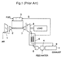
- This binary-fluid-cycle gas turbine system (called the Cheng cycle from the name of the inventor) is typically as shown in Fig. 1.
- the system consists of a choke valve 1, compressor 2, combustion chamber 3, water treatment equipment 4, pump 5, heat exchanger 6, turbines 7 and 8, condenser 9, etc.
- air drawn in from the atmosphere is compressed by the compressor 2 and supplied to the combustion chamber 3, and fuel is burned in the compressed air to produce a high-temperature combustion gas, and this combustion gas is used in turbines 7 and 8 thereby driving the compressor 2 and a load.
- steam is produced in the heat exchanger 6 using the combustion gas output from the turbines, and the condenser 9 removes moisture from the exhaust gas before it is discharged into the atmosphere.
- Such a Cheng cycle as described above has the advantage that the output and thermal efficiency of the turbine can be increased because the flow of combustion gas entering the turbine is larger and the specific heat of the combustion gas is increased because the steam S produced in the heat exchanger 6 is injected into the combustion chamber 3.
- the inventor of the present invention developed a binary-fluid-cycle gas turbine system which is an improvement on the aforementioned Cheng cycle, and has applied for a patent in the Japanese patent publication No. 26780, 1996.
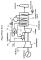
- the "partial-regeneration binary-fluid gas turbine” disclosed in the Japanese patent publication No. 26780, 1996 is shown schematically in Fig. 2. That is comprised of a gas turbine system provided with a compressor 2 for compressing air, a combustor 3 in which fuel is burned, and a turbine 7 driven by combustion gas and driving the compressor, a mixer 10 using steam S (saturated steam) as the driving source for boosting the pressure of the compressed air and in which the fluids are mixed, a superheater 6 provided downstream of the turbine 7 for heating the mixed gas produced in the mixer 10 using turbine exhaust, an exhaust heat boiler 12 located downstream of the superheater 6 for evaporating water using the turbine exhaust as the heat source, an air line 13 for introducing part of the compressed air produced in the compressor 2 into the combustor 3 and the rest into the mixer 10, a main steam line 14 for transferring part of the steam S produced in the exhaust heat boiler 13 to the mixer, and a mixed gas line 15 for introducing the mixed gas produced in the mixer 10 into the comb
- steam S is produced by the exhaust heat discharged from the gas turbine, drawn in and mixed with part of the compressed air, and after being heated in the superheater 6 by the exhaust from the gas turbine, the steam is injected into the combustor. Therefore, this type of gas turbine can recover more energy than with a Cheng cycle by the amount corresponding to the temperature increase of the air which is heated by the exhaust from the gas turbine, so the efficiency of the cycle can be increased.
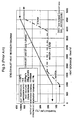
- Figs. 3 and 4 are exhaust heat recovery diagrams for the aforementioned Cheng cycle and the binary-fluid gas turbine.
- the abscissas and ordinates are the heat content of the exhaust gas of the gas turbine during the heat exchange and temperature, respectively. More precisely, the abscissa shows the enthalpy of the exhaust gas front the gas turbine using 0°C as the reference.
- exhaust gas from the gas turbine is cooled from about 550°C to about 150°C, and correspondingly, the water is heated up to saturation temperature at which the water is evaporated to produce saturated steam, and then it is further heated to produce superheated steam.
- the amount of compressed air drawn in the mixer 10 should be increased in order to increase the cycle efficiency.
- the pressure of the steam produced by the exhaust heat and which drives the mixer is solely increased, the flow of the steam to the mixer 10 is reduced, and as a result, the amount of heat recovered becomes insufficient.
- Fig. 5 shows an example of this situation in which the steam pressure is increased from the 20 kg/cm 2 g of Fig. 4 to 63 kg/cm 2 g.
- the temperature of the saturated steam is increased from about 210°C to about 280°C, which means it is closer to the temperature of the exhaust gas.
- the area between lines for the temperature of the steam and the exhaust gas correspond to the so-called exergy loss (inactive energy), therefore, this is an improvement to some extent, but because the flow of generated steam decreases there is a resulting reduction in the flow of feed water, consequently the heat in the exhaust gas can be recovered only down to about 200°C, so the amount of recovered energy corresponding to the hatched area in Fig. 5 is smaller than that in Fig. 4.
- the efficiency at the generator terminals for this example in Fig. 5 is decreased to 40.96% from the 41.18% in the case Fig. 4.
- an object of the present invention is to provide such a partial-regeneration binary-fluid gas turbine wherein the pressure of the driving steam is increased without reducing the flow of generated steam, thereby reducing the exergy loss in the exhaust heat recovery portion, and increasing the efficiency of power generation.
- a dual-pressure steam-injection-type partial-regeneration-cycle gas turbine is provided in the partial-regeneration-cycle gas turbine system wherein part of the air compressed in the compressor (2) is extracted before the combustor (3) and mixed with steam, and after being superheated by exhaust heat from the turbine, the mixed gas is injected into the combustor; high-pressure steam is used as the fluid for driving the mixer that compresses the extracted air, thereby increasing the ratio of extracted air to steam, furthermore low-pressure steam taken from the low-pressure exhaust heat boiler is mixed with the gas mixture of extracted air and steam, and then the mixture of the mixed gas and the low-pressure steam is superheated by exhaust heat from the turbine and the mixture is injected into the combustor.
- the pressure of the exhaust heat recovery steam is raised and the resultant high-pressure steam is used as the driving source for the mixer. Therefore the ratio of extracted air to steam is increased, so that the flow of compressed air drawn in at the mixer can be increased. Also because low-pressure steam from the low-pressure exhaust heat boiler is mixed with the gas mixture of extracted air and steam, so a greater amount of air and steam than with a conventional system can be supplied to the combustor. Thereby there is an increase in the flow of exhaust gas from which heat can be recovered, therefore, after exhaust heat has been recovered from this exhaust gas once by generating high-pressure steam, additional exhaust heat can be recovered by generating low-pressure steam, that is, the heat in the exhaust gas can be utilized down to a low temperature.
- the above-mentioned configuration of the present invention therefore, can increase the flow of compressed air, which is useful for recovering exhaust heat, and at the same time, the amount of exhaust heat recovered in the low-temperature range of the exhaust gas is increased, thereby the exergy loss in the exhaust heat recovery portion can be reduced and the efficiency of power generation can be made higher.
- the system is provided with a first mixer (22) that boosts the pressure of the compressed air using high-pressure steam as the driving source and in which the two fluids are mixed, a second mixer (24) that further mixes the mixed gas produced in the first mixer with low-pressure steam, a superheater (6) provided downstream of the turbine (7) for heating the mixture of gas produced in the second mixer with exhaust heat from the turbine, and an exhaust heat boiler (26) located downstream of the superheater for producing high-pressure steam and low-pressure steam using exhaust from the turbine as the heat source.
- a first mixer that boosts the pressure of the compressed air using high-pressure steam as the driving source and in which the two fluids are mixed
- a second mixer that further mixes the mixed gas produced in the first mixer with low-pressure steam
- a superheater (6) provided downstream of the turbine (7) for heating the mixture of gas produced in the second mixer with exhaust heat from the turbine
- an exhaust heat boiler (26) located downstream of the superheater for producing high-pressure steam and low-pressure steam using exhaust from the turbine as the
- the pressure of the compressed air of about 15 ata can be further boosted to the pressure of the low-pressure steam (for instance, about 20 ata), and the two fluids can be mixed. Also because high-pressure steam and low-pressure steam are generated in the exhaust heat boiler (26) using exhaust from the turbine as the heat source, the amount of heat recovered from the exhaust gas in the low-temperature range of the exhaust gas can be increased, thereby reducing the exergy loss in the heat recovery portion.
- Other component devices of the present invention include an air line (13) that supplies part of the compressed air produced in the compressor (2) to the combustor (3) and the rest to the first mixer (22), a main steam line (28a) for supplying high-pressure steam produced in the exhaust heat boiler (26) to the first mixer, a secondary steam line (28b) for supplying low-pressure steam produced in the exhaust heat boiler (26) to the second mixer, and a mixed gas line (15) that transfers the gas mixture produced in the second mixer to the combustor 3 via the superheater 6.
- first mixer (22) should preferably be an ejector which is driven by high-pressure steam and draws in compressed air
- second mixer (24) can preferably be a mixing vessel in which the mixed gas and the steam have substantially the same pressure
- the ejector is injected with high-pressure steam, and air from the outlet of the compressor of the gas turbine can be drawn in and mixed with the high-pressure steam, the driving fluid, thereby it is easy to produce a mixture of air and steam with a pressure that is higher than that of the compressed air, so that exergy loss can be avoided in the second mixer and the mixed gas can be mixed with the steam with a high efficiency.
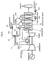
- Fig. 6 is a diagram showing the general configuration of the dual-pressure steam-injection-type partial-regeneration-cycle gas turbine according to the present invention.
- the partial-regeneration-cycle gas turbine system according to the present invention is provided with a gas turbine configured with a compressor 2 for compressing air A, a combustor 3 for burning a fuel F, and a turbine 7 driven by combustion gas E which drives the compressor 2, a superheater 6 located downstream of the turbine 7, an air line 13 for supplying part of the compressed air produced in the compressor 2 to the combustor and the rest to the mixer, and a mixed gas line 15 for transferring the air and steam mixture (gas mixture) to the combustor 3 via the superheater 6.
- Other component devices of the partial-regeneration-cycle gas turbine system include a first mixer 22 driven by high-pressure steam for boosting the pressure of the compressed air and mixing the two fluids, a second mixer 24 that further mixes the mixed gas produced in the first mixer 22 with low-pressure steam, and an exhaust heat boiler 26 located downstream of the superheater 6 for producing high-pressure steam and low-pressure steam using the exhaust from the turbine as the heat source.
- the superheater 6 installed downstream of the turbine 7 additionally heats the gas mixture produced in the second mixer 24 using exhaust heat from the turbine.
- the exhaust heat boiler 26 is provided with a low-pressure water supply pump 26a and, a high-pressure water supply pump 26b, and produces low-pressure steam at about 20 kg/cm 2 g and high-pressure steam at about 63 kg/cm 2 g, for example.
- the first mixer 22 is an ejector driven by high-pressure steam which draws in compressed air.
- the second mixer 24 is a mixing vessel in which the mixed gas from the first mixer 22 and the steam (low-pressure steam) are at substantially the same pressure.
- a mixing device of any other type with a small pressure loss can also be used as the second mixer 24.
- the pressure at the outlet of the first mixer 22 is set to be at substantially the same pressure as the low-pressure steam, while the pressure at the outlet of the second mixer 24 is adjusted to the inlet pressure required for the superheater. This configuration allows the steam and the mixed gas to be mixed in the mixing vessel with a small exergy loss.
- the partial-regeneration-cycle gas turbine system is also provided with a main steam line 28a for supplying high-pressure steam produced in the exhaust heat boiler 26 to the first mixer 22, and a secondary steam line 28b that transfers low-pressure steam produced in the exhaust heat boiler 26 to the second mixer 24.
- a high-pressure steam flow adjusting valve 29 is installed in the main steam line 28a, to adjust the steam flow to the mixer 22.
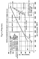
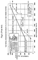
- Fig. 7 is a diagram showing the exhaust heat recovery for the system shown in Fig. 6.
- the heat content of the exhaust from the gas turbine (enthaly relative to a base of 0°C exhaust gas from the gas turbine) is plotted along the abscissa, and temperature is plotted as the ordinate.
- the exhaust heat boiler 26 is supplied with water (at about 50°C, for instance) from the low-pressure feed water pump 26a, and part of the water is converted to low-pressure saturated steam (at about 20 kg/cm 2 g, for example) and supplied to the second mixer 24 through a low-pressure drum and the secondary steam line 28b.
- the evaporation line for this low-pressure steam is the line at a constant temperature of about 210°C in Fig. 7.
- high-pressure steam in this case, high-pressure saturated steam
- This high-pressure steam is supplied to the first mixer 22 through the high-pressure steam flow adjusting valve 29 and the main steam line 28a.
- the evaporation line for this high-pressure steam is the line at the constant temperature of about 280°C in Fig. 7. In fact, the temperature of the mixed gas produced in the first mixer 22 is increased to about 360°C.
- the configuration of the present invention provides two places in which the temperatures of the saturated steam have constant levels of about 210°C and about 280°C each of which is close to the temperature of the exhaust gas. Therefore, the area between the exhaust heat recovery curve and the exhaust gas temperature curve, that is the so-called exergy loss (inactive energy) is small. In addition, the total volume of generated steam is also increased, and as a result, the flow of the feed water supply increases too, consequently, heat in the exhaust gas can be recovered down to a gas temperature of about 150°C.
- the recovered energy corresponding to the hatched area shown in Fig. 7 is greater than that in Fig. 5; obviously with this example, the efficiency at the generator end can be improved from the conventional maximum of about 41.18% to 42.5%, that is, by about 3 to 5%.
- the ratio of extracted air to steam can be raised, and the flow of compressed air drawn in at the mixer 22 can be increased.
- the mixture of air and steam produced in this way is mixed with low-pressure steam from the low-pressure exhaust heat boiler, more air and steam can be supplied to the combustor than in a conventional system known in the prior art.
- the flow of exhaust gas from which heat is recovered becomes greater, and the heat in this exhaust gas can be used to produce high-pressure steam and then low-pressure steam, so that heat can be recovered from the exhaust gas down to a low temperature with a small exergy loss.
- the pressure of the compressed air of about 15 ata can be increased further to the pressure of the low-pressure steam (for instance, about 20 ata), and both fluids can be mixed together.
- the heat to be recovered in the low-temperature range of the exhaust gas can be increased, thereby reducing the exergy loss in the exhaust heat recovery portion.
- both lines are independent from each other, and the pressures, temperatures, flows, etc. thereof can be set to give optimum conditions.
- the ejector draws in air from the outlet of the compressor of the gas turbine by the injected flow of high-pressure steam, mixes the air with high-pressure steam that is the driving fluid, and a mixture of air and steam with a pressure higher than that of the compressed air can be easily obtained.
- the mixing vessel with a low pressure loss can reduce the exergy loss and efficiently combine the mixed gas and steam.
- the dual-pressure steam injection partial-regeneration-cycle gas turbine system according to the present invention can increase the pressure of the driving steam without reducing the amount of steam generated, thereby the exergy loss in the exhaust heat recovery portion can be reduced, and the efficiency of power generation can be improved, etc., which are preferred advantages.
Landscapes
- Engineering & Computer Science (AREA)
- Chemical & Material Sciences (AREA)
- Combustion & Propulsion (AREA)
- Mechanical Engineering (AREA)
- General Engineering & Computer Science (AREA)
- Engine Equipment That Uses Special Cycles (AREA)
Applications Claiming Priority (2)
| Application Number | Priority Date | Filing Date | Title |
|---|---|---|---|
| JP11202962A JP2001027131A (ja) | 1999-07-16 | 1999-07-16 | 複圧蒸気噴射型部分再生サイクルガスタービン |
| JP20296299 | 1999-07-16 |
Publications (3)
| Publication Number | Publication Date |
|---|---|
| EP1069282A2 true EP1069282A2 (de) | 2001-01-17 |
| EP1069282A3 EP1069282A3 (de) | 2003-03-12 |
| EP1069282B1 EP1069282B1 (de) | 2006-01-11 |
Family
ID=16466058
Family Applications (1)
| Application Number | Title | Priority Date | Filing Date |
|---|---|---|---|
| EP00114680A Expired - Lifetime EP1069282B1 (de) | 1999-07-16 | 2000-07-07 | Zweidruck-Gasturbinensystem mit partieller Regeneration und Dampfeinspritzung |
Country Status (4)
| Country | Link |
|---|---|
| US (1) | US6233940B1 (de) |
| EP (1) | EP1069282B1 (de) |
| JP (1) | JP2001027131A (de) |
| DE (1) | DE60025415T2 (de) |
Cited By (2)
| Publication number | Priority date | Publication date | Assignee | Title |
|---|---|---|---|---|
| US8033116B2 (en) | 2008-05-06 | 2011-10-11 | General Electric Company | Turbomachine and a method for enhancing power efficiency in a turbomachine |
| EP2511487A3 (de) * | 2011-04-13 | 2014-03-19 | General Electric Company | Kombikraftwerk |
Families Citing this family (25)
| Publication number | Priority date | Publication date | Assignee | Title |
|---|---|---|---|---|
| EP1454042B1 (de) * | 2001-12-05 | 2007-04-25 | Lawrence G. Clawson | Ottomotor mit hohem wirkungsgrad und mit expander für energieerzeugung |
| EP1786725A2 (de) * | 2004-06-11 | 2007-05-23 | Nuvera Fuel Cells, Inc. | Brennstoffbetriebener wasserstoffgenerator |
| US7185495B2 (en) | 2004-09-07 | 2007-03-06 | General Electric Company | System and method for improving thermal efficiency of dry low emissions combustor assemblies |
| US7644587B2 (en) * | 2005-12-21 | 2010-01-12 | Rentech, Inc. | Method for providing auxiliary power to an electric power plant using fischer-tropsch technology |
| FR2914011A1 (fr) * | 2007-03-23 | 2008-09-26 | Joseph Haiun | Centrale electrique a pression atmospherique |
| NO327501B1 (no) * | 2007-09-20 | 2009-07-27 | Statoil Asa | Anlegg for forbrenning av naturgass |
| US8443606B2 (en) * | 2008-03-26 | 2013-05-21 | Babcock & Wilcox Power Generation Group, Inc. | Enhanced steam cycle utilizing a dual pressure recovery boiler with reheat |
| DE102008018664B4 (de) * | 2008-04-11 | 2014-10-30 | Botec - Forschungs- Und Entwicklungsgesellschaft Mbh | Vorrichtung zur Zufuhr von Wasserdampf über einen Wärmetauscher in einen Brennraum und Verfahren |
| CN102575531A (zh) * | 2009-08-24 | 2012-07-11 | 贝努瓦·詹维尔 | 用于生成高压蒸汽的方法和系统 |
| WO2011102408A1 (ja) * | 2010-02-19 | 2011-08-25 | 株式会社Ihi | 排熱回収システム、エネルギ供給システム及び排熱回収方法 |
| US9358859B2 (en) * | 2011-11-30 | 2016-06-07 | Carrier Corporation | Transport refrigeration system powered by diesel engine with pressurized combustion air |
| US9038389B2 (en) * | 2012-06-26 | 2015-05-26 | Harris Corporation | Hybrid thermal cycle with independent refrigeration loop |
| WO2014080984A1 (ja) | 2012-11-22 | 2014-05-30 | Uji Shigekazu | 揮発性有機化合物回収装置 |
| EP2957731A1 (de) * | 2014-06-18 | 2015-12-23 | Alstom Technology Ltd | Verfahren zur Leistungssteigerung eines Kombikraftwerks und Kombikraftwerk zur Durchführung des Verfahrens |
| KR101688277B1 (ko) * | 2014-12-02 | 2016-12-29 | 재단법인 포항산업과학연구원 | 가열로의 폐열 회수장치 및 방법 |
| US10072573B2 (en) * | 2015-12-15 | 2018-09-11 | General Electric Company | Power plant including an ejector and steam generating system via turbine extraction |
| US9890710B2 (en) * | 2015-12-15 | 2018-02-13 | General Electric Company | Power plant with steam generation via combustor gas extraction |
| US9976479B2 (en) * | 2015-12-15 | 2018-05-22 | General Electric Company | Power plant including a static mixer and steam generating system via turbine extraction and compressor extraction |
| US9970354B2 (en) * | 2015-12-15 | 2018-05-15 | General Electric Company | Power plant including an ejector and steam generating system via turbine extraction and compressor extraction |
| US9964035B2 (en) * | 2015-12-15 | 2018-05-08 | General Electric Company | Power plant including exhaust gas coolant injection system and steam generating system via turbine extraction |
| MX2018014295A (es) * | 2016-06-17 | 2019-03-14 | Siemens Ag | Recirculacion de condensacion de agua. |
| JP6905329B2 (ja) * | 2016-11-25 | 2021-07-21 | 三菱パワー株式会社 | 熱交換システム及びその運転方法、ガスタービンの冷却システム及び冷却方法、並びにガスタービンシステム |
| KR102011067B1 (ko) * | 2018-03-07 | 2019-10-14 | 두산중공업 주식회사 | 가스 터빈 및 가스 터빈의 구동 방법 |
| US12577904B2 (en) * | 2023-04-28 | 2026-03-17 | Rtx Corporation | Offset core with side ejector nacelle nozzles |
| CN118327781B (zh) * | 2024-06-13 | 2024-09-20 | 中国航发燃气轮机有限公司 | 一种燃气轮机 |
Citations (1)
| Publication number | Priority date | Publication date | Assignee | Title |
|---|---|---|---|---|
| JPS5434865A (en) | 1977-08-24 | 1979-03-14 | Fujitsu Ten Ltd | Liquid level detector for battery |
Family Cites Families (7)
| Publication number | Priority date | Publication date | Assignee | Title |
|---|---|---|---|---|
| FR1168070A (fr) * | 1955-12-09 | 1958-12-04 | Installation génératrice de vapeur et de puissance | |
| US3518830A (en) * | 1968-10-17 | 1970-07-07 | Westinghouse Electric Corp | Vapor heated tube and shell heat exchanger system and method of purging |
| US5392606A (en) * | 1994-02-22 | 1995-02-28 | Martin Marietta Energy Systems, Inc. | Self-contained small utility system |
| DE4415315A1 (de) * | 1994-05-02 | 1995-11-09 | Abb Management Ag | Kraftwerksanlage |
| US5896740A (en) * | 1996-09-12 | 1999-04-27 | Shouman; Ahmad R. | Dual cycle turbine engine having increased efficiency and heat recovery system for use therein |
| JP3646834B2 (ja) * | 1996-12-27 | 2005-05-11 | 石川島播磨重工業株式会社 | ガスタービン発電装置 |
| US6003298A (en) * | 1997-10-22 | 1999-12-21 | General Electric Company | Steam driven variable speed booster compressor for gas turbine |
-
1999
- 1999-07-16 JP JP11202962A patent/JP2001027131A/ja active Pending
-
2000
- 2000-07-07 EP EP00114680A patent/EP1069282B1/de not_active Expired - Lifetime
- 2000-07-07 DE DE60025415T patent/DE60025415T2/de not_active Expired - Lifetime
- 2000-07-10 US US09/613,460 patent/US6233940B1/en not_active Expired - Lifetime
Patent Citations (1)
| Publication number | Priority date | Publication date | Assignee | Title |
|---|---|---|---|---|
| JPS5434865A (en) | 1977-08-24 | 1979-03-14 | Fujitsu Ten Ltd | Liquid level detector for battery |
Cited By (2)
| Publication number | Priority date | Publication date | Assignee | Title |
|---|---|---|---|---|
| US8033116B2 (en) | 2008-05-06 | 2011-10-11 | General Electric Company | Turbomachine and a method for enhancing power efficiency in a turbomachine |
| EP2511487A3 (de) * | 2011-04-13 | 2014-03-19 | General Electric Company | Kombikraftwerk |
Also Published As
| Publication number | Publication date |
|---|---|
| US6233940B1 (en) | 2001-05-22 |
| JP2001027131A (ja) | 2001-01-30 |
| EP1069282B1 (de) | 2006-01-11 |
| DE60025415T2 (de) | 2006-07-20 |
| EP1069282A3 (de) | 2003-03-12 |
| DE60025415D1 (de) | 2006-04-06 |
Similar Documents
| Publication | Publication Date | Title |
|---|---|---|
| EP1069282B1 (de) | Zweidruck-Gasturbinensystem mit partieller Regeneration und Dampfeinspritzung | |
| RU2215165C2 (ru) | Способ регенерации тепла выхлопных газов в преобразователе органической энергии с помощью промежуточного жидкостного цикла (варианты) и система регенерации тепла выхлопных газов | |
| US6684643B2 (en) | Process for the operation of a gas turbine plant | |
| KR101760477B1 (ko) | 가스 터빈 에너지 보조 시스템 및 가열 시스템, 그리고 그 제작 및 이용 방법 | |
| US20150369125A1 (en) | Method for increasing the power of a combined-cycle power plant, and combined-cycle power plant for conducting said method | |
| US4891937A (en) | Heat recovery system | |
| US20010047646A1 (en) | Apparatus and methods of reheating gas turbine cooling steam and hp steam turbine exhaust in a combined cycle power generating system | |
| JPH08114104A (ja) | 複合ガス・蒸気タ−ビン動力プラント | |
| CN105518258B (zh) | 燃气涡轮装置及其操作方法 | |
| JPH08510311A (ja) | 中間冷却と復熱を用いた高能率多軸再熱タービン | |
| JPS6388227A (ja) | ガスタ−ビンユニツト作動方法 | |
| CN1661202A (zh) | 蒸汽轮机设备 | |
| US6389796B1 (en) | Gas turbine system and combined plant comprising the same | |
| JP2870232B2 (ja) | 石炭ガス化発電プラント | |
| US20100115962A1 (en) | Methods and systems for gas turbine syngas warm-up with low emissions | |
| CA2429938C (en) | A turbine arrangement and a method of operating a turbine arrangement | |
| JPH08210151A (ja) | パワープラント | |
| US4545208A (en) | Method of operating an industrial furnace | |
| RU2561770C2 (ru) | Способ работы парогазовой установки | |
| JPH01117903A (ja) | 組合されたガス‐蒸気タービン‐発電装置の出力調整装置 | |
| CN102046929A (zh) | 空气分离设备和蒸汽再热循环的集成 | |
| JPH06212909A (ja) | 複合発電プラント | |
| KR102473756B1 (ko) | 복합 발전 시스템 및 복합 발전 시스템의 구동 방법 | |
| KR20220136294A (ko) | 복합 발전 시스템 및 복합 발전 시스템의 구동 방법 | |
| JPH10325336A (ja) | ガスタービン発電システム |
Legal Events
| Date | Code | Title | Description |
|---|---|---|---|
| PUAI | Public reference made under article 153(3) epc to a published international application that has entered the european phase |
Free format text: ORIGINAL CODE: 0009012 |
|
| AK | Designated contracting states |
Kind code of ref document: A2 Designated state(s): AT BE CH CY DE DK ES FI FR GB GR IE IT LI LU MC NL PT SE |
|
| AX | Request for extension of the european patent |
Free format text: AL;LT;LV;MK;RO;SI |
|
| 17P | Request for examination filed |
Effective date: 20010531 |
|
| PUAL | Search report despatched |
Free format text: ORIGINAL CODE: 0009013 |
|
| AK | Designated contracting states |
Kind code of ref document: A3 Designated state(s): AT BE CH CY DE DK ES FI FR GB GR IE IT LI LU MC NL PT SE |
|
| AX | Request for extension of the european patent |
Extension state: AL LT LV MK RO SI |
|
| AKX | Designation fees paid |
Designated state(s): DE FR GB IT |
|
| GRAP | Despatch of communication of intention to grant a patent |
Free format text: ORIGINAL CODE: EPIDOSNIGR1 |
|
| GRAC | Information related to communication of intention to grant a patent modified |
Free format text: ORIGINAL CODE: EPIDOSCIGR1 |
|
| GRAS | Grant fee paid |
Free format text: ORIGINAL CODE: EPIDOSNIGR3 |
|
| GRAA | (expected) grant |
Free format text: ORIGINAL CODE: 0009210 |
|
| AK | Designated contracting states |
Kind code of ref document: B1 Designated state(s): DE FR GB IT |
|
| REF | Corresponds to: |
Ref document number: 60025415 Country of ref document: DE Date of ref document: 20060406 Kind code of ref document: P |
|
| ET | Fr: translation filed | ||
| PLBE | No opposition filed within time limit |
Free format text: ORIGINAL CODE: 0009261 |
|
| STAA | Information on the status of an ep patent application or granted ep patent |
Free format text: STATUS: NO OPPOSITION FILED WITHIN TIME LIMIT |
|
| 26N | No opposition filed |
Effective date: 20061012 |
|
| REG | Reference to a national code |
Ref country code: FR Ref legal event code: PLFP Year of fee payment: 17 |
|
| REG | Reference to a national code |
Ref country code: FR Ref legal event code: PLFP Year of fee payment: 18 |
|
| REG | Reference to a national code |
Ref country code: FR Ref legal event code: PLFP Year of fee payment: 19 |
|
| PGFP | Annual fee paid to national office [announced via postgrant information from national office to epo] |
Ref country code: FR Payment date: 20190619 Year of fee payment: 20 |
|
| PGFP | Annual fee paid to national office [announced via postgrant information from national office to epo] |
Ref country code: IT Payment date: 20190719 Year of fee payment: 20 Ref country code: DE Payment date: 20190625 Year of fee payment: 20 |
|
| PGFP | Annual fee paid to national office [announced via postgrant information from national office to epo] |
Ref country code: GB Payment date: 20190703 Year of fee payment: 20 |
|
| REG | Reference to a national code |
Ref country code: DE Ref legal event code: R082 Ref document number: 60025415 Country of ref document: DE Representative=s name: GRUENECKER PATENT- UND RECHTSANWAELTE PARTG MB, DE Ref country code: DE Ref legal event code: R081 Ref document number: 60025415 Country of ref document: DE Owner name: IHI POWER SYSTEMS CO., LTD., JP Free format text: FORMER OWNER: ISHIKAWAJIMA-HARIMA HEAVY INDUSTRIES CO., LTD., TOKYO, JP |
|
| REG | Reference to a national code |
Ref country code: DE Ref legal event code: R071 Ref document number: 60025415 Country of ref document: DE |
|
| REG | Reference to a national code |
Ref country code: GB Ref legal event code: 732E Free format text: REGISTERED BETWEEN 20200618 AND 20200624 |
|
| REG | Reference to a national code |
Ref country code: GB Ref legal event code: PE20 Expiry date: 20200706 |
|
| PG25 | Lapsed in a contracting state [announced via postgrant information from national office to epo] |
Ref country code: GB Free format text: LAPSE BECAUSE OF EXPIRATION OF PROTECTION Effective date: 20200706 |