EP1069261B1 - Verstellbare Rettungsstütze - Google Patents
Verstellbare Rettungsstütze Download PDFInfo
- Publication number
- EP1069261B1 EP1069261B1 EP00305873A EP00305873A EP1069261B1 EP 1069261 B1 EP1069261 B1 EP 1069261B1 EP 00305873 A EP00305873 A EP 00305873A EP 00305873 A EP00305873 A EP 00305873A EP 1069261 B1 EP1069261 B1 EP 1069261B1
- Authority
- EP
- European Patent Office
- Prior art keywords
- cylindrical
- sleeve
- cylindrical sleeve
- outer housing
- strut
- Prior art date
- Legal status (The legal status is an assumption and is not a legal conclusion. Google has not performed a legal analysis and makes no representation as to the accuracy of the status listed.)
- Expired - Lifetime
Links
- 230000000717 retained effect Effects 0.000 claims abstract description 4
- 238000004904 shortening Methods 0.000 description 2
- 238000009412 basement excavation Methods 0.000 description 1
- 238000007789 sealing Methods 0.000 description 1
Images


Classifications
-
- E—FIXED CONSTRUCTIONS
- E21—EARTH OR ROCK DRILLING; MINING
- E21D—SHAFTS; TUNNELS; GALLERIES; LARGE UNDERGROUND CHAMBERS
- E21D15/00—Props; Chocks, e.g. made of flexible containers filled with backfilling material
- E21D15/50—Component parts or details of props
- E21D15/56—Details of locks of telescopic props
-
- E—FIXED CONSTRUCTIONS
- E04—BUILDING
- E04G—SCAFFOLDING; FORMS; SHUTTERING; BUILDING IMPLEMENTS OR AIDS, OR THEIR USE; HANDLING BUILDING MATERIALS ON THE SITE; REPAIRING, BREAKING-UP OR OTHER WORK ON EXISTING BUILDINGS
- E04G25/00—Shores or struts; Chocks
- E04G25/04—Shores or struts; Chocks telescopic
- E04G25/06—Shores or struts; Chocks telescopic with parts held together by positive means
- E04G25/065—Shores or struts; Chocks telescopic with parts held together by positive means by a threaded nut
-
- E—FIXED CONSTRUCTIONS
- E21—EARTH OR ROCK DRILLING; MINING
- E21D—SHAFTS; TUNNELS; GALLERIES; LARGE UNDERGROUND CHAMBERS
- E21D15/00—Props; Chocks, e.g. made of flexible containers filled with backfilling material
- E21D15/14—Telescopic props
- E21D15/44—Hydraulic, pneumatic, or hydraulic-pneumatic props
-
- E—FIXED CONSTRUCTIONS
- E04—BUILDING
- E04G—SCAFFOLDING; FORMS; SHUTTERING; BUILDING IMPLEMENTS OR AIDS, OR THEIR USE; HANDLING BUILDING MATERIALS ON THE SITE; REPAIRING, BREAKING-UP OR OTHER WORK ON EXISTING BUILDINGS
- E04G25/00—Shores or struts; Chocks
- E04G25/04—Shores or struts; Chocks telescopic
- E04G2025/047—Shores or struts; Chocks telescopic which telescoping action effected by a piston
-
- Y—GENERAL TAGGING OF NEW TECHNOLOGICAL DEVELOPMENTS; GENERAL TAGGING OF CROSS-SECTIONAL TECHNOLOGIES SPANNING OVER SEVERAL SECTIONS OF THE IPC; TECHNICAL SUBJECTS COVERED BY FORMER USPC CROSS-REFERENCE ART COLLECTIONS [XRACs] AND DIGESTS
- Y10—TECHNICAL SUBJECTS COVERED BY FORMER USPC
- Y10T—TECHNICAL SUBJECTS COVERED BY FORMER US CLASSIFICATION
- Y10T74/00—Machine element or mechanism
- Y10T74/20—Control lever and linkage systems
- Y10T74/20576—Elements
- Y10T74/20636—Detents
- Y10T74/20666—Lever engaging
Definitions
- the present invention relates to a continuously adjustable rescue strut intended to be used as a temporary strut for maintain two objects in a spaced position with respect to each other. More particularly, it relates to a strut of continuously adjustable length intended for use by emergency or rescue personnel to support portions of collapsed building or other structures, such as the wall or a collapsing excavation, in a spaced relationship with respect to each other, so as to permit rescue operations to proceed without the danger of the supported portions moving into a closer position with respect to each other.
- Adjustable length rescue support or strut systems have been provided in the past for use by emergency and rescue personnel for maintaining structures in a spaced relationship with respect to each other.
- strut systems are constructed with an inner member being telescopically received in an outer member.
- the opposite ends of the inner and outer members are each provided with a base suitable for engaging the surface to be supported.
- a mechanism is provided to maintain the inner and outer members in a desired telescopic relationship with each other, whereby the length of the strut is such that each of the bases engages the surface to be supported.
- struts have been formed by inner and outer strut members, each of which is provided with a series of holes perpendicular to and spaced apart along the major axis of each member.
- the inner and outer members are extended with respect to each other to the desired overall length, and then adjusted with respect to each other to permit a pin to be place in aligned holes in the inner and outer members.
- a strut of this type is not preferred by rescue personnel, wherein a person must not only place the strut between the surfaces to be supported, but must also adjust the strut to the desired length and then place a pin in aligned holes in the inner and outer members. Thus, the rescue person is exposed to possible shifting of the surfaces to be supported both before and after the strut is in place.
- the assignee of the subject application has provided a variety of rescue support or strut systems which are preferred to that just described.
- the strut systems provided by the assignee of the subject application are designed to be extendable to a desired length, either manually or by remote operation.
- the inner and outer members are designed to form a cylinder to which pneumatic pressure may be applied to extend the members with respect to each other.
- the inner member is provided with a plurality of spaced circumferential notches which receive ball bearings supported in a collar mechanism attached to the outer member.
- the collar mechanism is movable with respect to the outer member between two positions. With the collar in a first position the inner member is freely movable with respect to the outer member. With the collar in the second position and a compressive or no force applied to the free ends of the strut, the ball bearings are engaged in the notches in the inner member to lock the inner and outer members in position with respect to each other.
- the collar is operable between the two positions, either manual or by pneumatic pressure. If a remote handling device is used to place the strut between the surfaces to be supported, the extension and securing in position of the inner and outer members with respect to each other can be accomplished by pneumatic pressure supply through hoses, such that a rescue person need not be endangered by manually positioning the strut system.
- a limitation on this strut system is that the length is not continuously adjustable. Rather, the length is incrementally adjustable, depending on the spacing of the grooves in the inner member. In a strut system provided by the assignee of this application, the increment is 0.40 inches (10.2 millimeters).
- the strut be adjustable to the exact spacing of the surfaces to be supported, such that even a slight shifting of the surfaces toward each other is not possible with the strut in place.
- the assignee of this application has provided a strut system which is continuously adjustable in length, and which as in the case of the previously described strut system may be remotely extend by pneumatic pressure.
- the inner and outer members are designed to form a cylinder to which pneumatic pressure may be applied to extend the members with respect to each other.
- the outer surface of the inner member is provided with an Acme thread, which is engaged by an Acme threaded nut. After the strut is extended to the desired length, the acme nut is rotated to engage the end of the outer member.
- this strut system may be continuously adjusted in length, such that it can be remotely adjusted to the exact spacing of the surfaces to be supported, it does require the manual rotation of the acme nut to secure or lock the inner and outer members in the desired position with respect to each other.
- a strut system providing both continuous extension and locking by remote control has not been available.
- a continuously adjustable strut comprising: an outer housing with first and second ends having a cylindrical bore therein, a cylindrical extensible member with first and second ends, a first end of said cylindrical extensible member received in said cylindrical bore through a first end of said outer housing, a groove formed in the cylindrical surface of at least a portion of said cylindrical extensible member adjacent said second end, a collar secured to said first end of said outer housing portion, said collar comprising, an outer cylindrical sleeve, an inner cylindrical sleeve, said inner cylindrical sleeve secured to said outer cylindrical sleeve and being provided with a series of holes, an intermediate cylindrical sleeve, said intermediate cylindrical sleeve being provided with an internal groove, a plurality of ball bearings, said ball bearings being retained between said inner cylindrical sleeve and said intermediate cylindrical sleeve in said internal groove and said series of holes, a spring for applying a force between said outer sleeve and said intermediate sleeve in
- the invention provides for both remote extension of the length and locking at the desired length, and remote unlocking to permit retraction or shortening of the strut is provided.
- an continuously adjustable strut in accordance with a first embodiment of this invention is actuated by pressurized gas.
- the continuously adjustable strut 10 is connect to a supply of compressed gas, shown as a tank 12, by hoses 14, 16, and 18 through a control valve 20.
- a supply of compressed gas shown as a tank 12
- hoses 14, 16, and 18 the supply of compressed gas through the hose 16 to the continuously adjustable strut 10 will cause an inner cylindrical extensible portion 22 to be extended from an outer cylindrical housing portion 24, and the supply of compressed gas through the hose 18 will release the mechanism which holds the extensible portion 22 and housing portion 24 in an extended support position, such that extensible portion 22 may freely reciprocate with respect to housing portion 24.
- the control valve 20 is provided with control knobs 26 and 28 to control the supply of compressed gas to hoses 16 and 18 respectively.
- a continuously adjustable strut in accordance with the first embodiment of this invention includes outer cylindrical housing portion or tube 24 and inner cylindrical extensible portion or shaft 22.
- a mechanism for adjustably positioning the outer housing portion 24 and the inner extensible portion 22 with respect to each other is incorporated in a collar 30.
- the free end of housing portion 24 is provided with an annular groove 32 which may be used to secure a support plate 34, as represented by the dashed lines, to the housing portion 24.
- the free end of the inner extensible portion 22 is provided with an annular groove 36, which may be used to secure a support plate 38, represented by dashed lines, to the inner extensible portion 22.
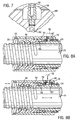
- Figs. 3A and 3B describe a first embodiment of the mechanism for adjustably positioning the outer housing portion 24 with respect to the inner extensible portion 22.
- the mechanism supports and retains ball bearings 40 in alternate positions with respect to the collar 30 and the inner extensible portion 22.
- a first position shown in Fig. 3A
- the ball bearings are positioned to support the inner extensible portion 22 with respect to the outer housing portion 24, by being engaged in a spiral groove 42 formed in the outer surface of the inner extensible portion 22.
- a second position shown in Fig. 3B, the ball bearings are disengaged from the spiral groove 42 in the inner extensible portion 22, such that the outer housing portion 24 may be freely reciprocated with respect to the inner extensible portion 22.
- the collar 30 including three cylindrical members, an outer cylindrical sleeve or release ring 44, and intermediate cylindrical sleeve, or pressure ring housing 46, having a spiral groove 48 formed therein, and an inner cylindrical sleeve, or unlocking ring 50, having holes 52 formed therein for receiving and maintaining the ball bearings 40 in spaced positions with respect to each other.
- the intermediate sleeve 46 is provided with internal threads 54 at a first end which engage external threads 56 on a first end of outer cylindrical housing portion 24, to maintain the intermediate sleeve 46 in a fixed position with respect to outer cylindrical housing portion 24.
- Outer cylindrical sleeve 44 is provided with internal threads 58 at a first end which engage external threads 60 on a first end of inner sleeve 50.
- Outer sleeve 44 and inner sleeve 50 which are secured to each other, may reciprocate with respect to intermediate sleeve 46 and cylindrical housing portion 24, which are secured to each other.
- Intermediate sleeve 46 is provided with a portion 62 of reduced outer diameter and outer sleeve 44 is provided with a portion 64 of reduce inner diameter to provide a cylindrical space in which a helical spring 66 is captured. As viewed in Figs.
- the helical spring 66 caused the inner sleeve 50 and the outer sleeve 44 to move to the right with respect to the intermediate sleeve 46 and the cylindrical housing portion 24.
- the application of a force F as shown in Fig. 3B, sufficient to overcome the force of the spring 66 will cause the outer sleeve 44, and inner sleeve 50 to move to the left with respect to the intermediate sleeve 46 and the cylindrical housing portion 24, as shown in Fig. 3B.
- This movement of the inner sleeve 50 causes the ball bearings 40 to be moved out of the spiral groove 48 in extensible portion 22 and into the spiral groove 48 in intermediate sleeve 46.
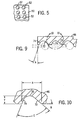
- the holes 52 in inner cylindrical sleeve 50 are formed in a spiral, which in the preferred embodiment makes two revolutions around the sleeve.
- the holes 52 are formed with a diameter slightly smaller that the diameter of the ball bearings 40, such that the ball bearings are confined by the inner sleeve 50 and internal spiral groove 48, formed in intermediate sleeve 46.
- the spiral in which the holes 52 are formed in the inner cylindrical sleeve 50, the internal spiral groove 48, and the spiral groove 42 all have the same pitch.
- the internal spiral groove 48 is formed with a curved base 70 and two sidewalls 72 and 74, which have different slopes as best seen in Figs. 9 and 10. With the sleeves in the position shown in Fig.
- the ball bearings are positioned to be retained in the holes 52, seated in the spiral groove 42 formed in the extensible portion 22, and to engage the sidewall 72 of the spiral groove 48 formed in intermediate sleeve 46.
- the sleeves With the sleeves in this position, movement of extensible portion 22 into housing portion 24 is resisted.
- the extensible portion 22 may be readily extended from housing portion 24, by the application of extensible force. An extensible force tending to move extensible portion 22 out of housing 24 will result in the ball bearings 40 being lifted out of the groove 42 and into engagement with the curved base 70 and sidewall 74 of the spiral groove 48 formed in the intermediate sleeve 46.
- the continuously adjustable strut of this invention may be readily adjusted to firmly engage two spaced surfaces, to maintain their spacing.
- the outer housing portion 24 With the sleeves of collar 30 in the position shown in Fig. 3A, the outer housing portion 24 may be rotated with respect to the extensible portion 22, thus causing the strut to be lengthened or shortened depending on the direction of rotation of the portions 22 and 24 with respect to each other.
- the ball bearings 40 and the spiral groove 42 act as threaded members with respect to each other.
- the other way to adjust the length is to apply an extensible force between the extensible portion 22 and the housing portion 24.
- the force F may be manually applied between the collar 30 and the housing portion 22, while at the same time manually applying a second force to move extensible portion 22 with respect to housing portion 22.
- the two forces may be applied by a compressed gas.
- an expansible chamber 76 may be formed between the outer sleeve 44 and the intermediate sleeve 46. The ends of the chamber are sealed by resilient sealing rings 78 and 80.
- a threaded hole 82 Is provided in outer sleeve 44 in communication with the chamber 76, to which the hose 18 in Fig. 1 may be secured.
- a compressed gas cylinder 84 may be formed by the cylindrical housing portion 24, end 86 of extensible portion 22, and a base 88, which is secured by threads to cylindrical housing portion 24.
- a passageway 90 is formed in base 88 to provide a flow path between the compressed gas cylinder 84 and a fitting 92 to which the hose 16 shown in Fig. 1 may be secured.
- the fitting 92 is positioned in a recess 94 in base 88, thereby protecting it from damage, which otherwise might occur if it projected outward from the base.
- control knob 26 is actuated to apply gas pressure through hose 16 to the compressed gas cylinder 84 to extend the extensible portion 22 from the housing portion 24.
- control knob 26 may again be actuated to terminate the application of gas pressure through hose 16.
- the collar elements are moved to the position shown in Fig. 8A, locking the extensible portion 22 and housing portion 24 in the position to which they were extended by the gas pressure applied to gas cylinder 84.
- control knob 28 is actuated to apply gas pressure through hose 18 to the expansible chamber 76, to position the collar elements in the position shown in Fig. 8B, whereby the extensible portion 22 and housing portion 24 may be freely reciprocated with respect to each other.
- the strut is provided with 40 ball bearings 11/32" (8.73 millimeters) in diameter.
- the threaded groove in the extensible portion has a radius of 0.180" (4.57mm) and is 0.103' (2.62mm) deep with a pitch of 0.600" (15.2mm).
- the radius 70 of the bottom of the spiral groove 68 is 0.172", with a depth of 0.195" (4.37mm).
- the angle A of side 74 is 20 degrees, and the angle B of side 72 is 42 degrees.
- the angle C of the sides 72 and 74 with respect to each other is 68 degrees.
- the holes in inner sleeve 50 are .332" (8.43mm) in diameter at the inner surface of the sleeve. The side of the holes sloping outwardly with opposite sides forming an angle of 20 degrees with respect to each other.
Landscapes
- Engineering & Computer Science (AREA)
- Architecture (AREA)
- Mechanical Engineering (AREA)
- Structural Engineering (AREA)
- Mining & Mineral Resources (AREA)
- Civil Engineering (AREA)
- Geochemistry & Mineralogy (AREA)
- Geology (AREA)
- General Life Sciences & Earth Sciences (AREA)
- Life Sciences & Earth Sciences (AREA)
- Fluid-Damping Devices (AREA)
- Emergency Lowering Means (AREA)
- Pivots And Pivotal Connections (AREA)
- Organic Low-Molecular-Weight Compounds And Preparation Thereof (AREA)
- Mutual Connection Of Rods And Tubes (AREA)
Claims (14)
- Stufenlos einstellbare Verstrebung (10), umfassend:ein äußeres Gehäuse (24) mit einem ersten und zweiten Ende, in denen eine zylindrische Bohrung vorgesehen ist,ein zylindrisches ausziehbares Element (22) mit einem ersten und zweiten Ende, wobei ein erstes Ende des genannten zylindrischen ausziehbaren Elements in der genannten zylindrischen Bohrung durch ein erstes Ende des genannten äußeren Gehäuses (24) aufgenommen wird, einer Nut (42), die in der zylindrischen Oberfläche mindestens eines Teils des genannten zylindrischen ausziehbaren Elements (22) angrenzend an das genannte zweite Ende ausgebildet ist,einen Bund (30), der an dem genannten ersten Ende des genannten äußeren Gehäuseteils befestigt ist, wobei der genannte Bund (30) umfasst:dadurch gekennzeichnet, dass die genannten Nuten (42, 48) spiralförmig sind,eine äußere zylindrische Hülse (44),eine innere zylindrische Hülse (50), wobei die genannte innere zylindrische Hülse an der genannten äußeren zylindrischen Hülse (44) befestigt ist und mit einer Reihe von Löchern (52) versehen ist,eine zylindrische Zwischenhülse (46), wobei die genannte zylindrische Zwischenhülse mit einer inneren Nut (48) versehen ist,eine Mehrzahl von Kugellagern (40), wobei die genannten Kugellager (40) zwischen der genannten inneren zylindrischen Hülse (50) und der genannten zylindrischen Zwischenhülse (46) in der genannten inneren Nut (48) und der genannten Reihe von Löchern (52) festgehalten werden,eine Feder (66) zum Anlegen einer Kraft zwischen der genannten äußeren Hülse (44) und der genannten Zwischenhülse (46), um die genannte äußere Hülse (44) und die genannte Zwischenhülse (46) in einer ersten Position in bezug zueinander zu halten, wobei in der genannten ersten Position die genannten Kugellager (40) in die genannte Nut (48) in dem genannten zylindrischen ausziehbaren Element (22) eingreifen, so dass Drehung der genannten äußeren Hülse (44) in Bezug zu dem genannten zylindrischen ausziehbaren Element (22) zur Anpassung der Position des genannten äußeren Gehäuses (24) in bezug zu dem genannten zylindrischen ausziehbaren Element (22) führen wird, wobei in der genannten ersten Position der genannte äußere Gehäuse- (24) Teil und das genannte zylindrische ausziehbare Element (22) einer zwischen dem zweiten Ende des äußeren Gehäuses und dem zweiten Ende des zylindrischen ausziehbaren Elements angelegten Kompressionskraft standhalten, und, wenn eine Kraft zwischen der genannten äußeren zylindrischen Hülse (44) und der genannten zylindrischen Zwischenhülse (46) angelegt wird, die genannte äußere zylindrische Hülse (44) und die genannte zylindrische Zwischenhülse (46) zum Überwinden der Kraft der genannten Feder (66) zu einer zweiten Position bewegt werden, in der die genannten Kugellager (40) aus der genannten Nut (42) in dem genannten zylindrischen ausziehbaren Element (22) gelöst sind und das genannte äußere Gehäuse (24) und das genannte zylindrische ausziehbare Element (22) in bezug zueinander hin- und herbewegt werden können,
und dass die genannte Reihe von Löchern (52) in einem Spiralmuster angeordnet ist. - Stufenlos einstellbare Verstrebung von Anspruch 1, bei der die genannte Zwischenhülse (46) an dem Ende des genannten äußeren Gehäuses (24) befestigt ist, und die genannte innere zylindrische Hülse (50) und die genannte äußere zylindrische Hülse (44) aneinander befestigt werden, so dass eine der Kraft der genannten Spiralfeder (66) entgegengerichtete Kraft, die zwischen der genannten äußeren zylindrischen Hülse (44) und dem genannten äußeren Gehäuseteil (24) angelegt wird, Zusammendrücken der genannten Spiralfeder (66) verursachen wird, wodurch die genannten Kugellager (40) aus der genannten Nut (42) in dem genannten zylindrischen ausziehbaren Teil (22) gelöst werden, so dass der genannte äußere Gehäuseteil (24) und der genannte zylindrische ausziehbare Teil (22) in bezug zueinander hin- und herbewegt werden können.
- Stufenlos einstellbare Verstrebung nach Anspruch 1 oder 2, bei der die genannte innere zylindrische Hülse (50) mit Außengewinden (60) versehen ist, und die genannte äußere zylindrische Hülse (44) mit Innengewinden (58) versehen ist, welche Gewinde miteinander in Eingriff gebracht werden, um die innere und äußere Hülse (50, 44) aneinander zu befestigen.
- Stufenlos einstellbare Verstrebung nach Anspruch 1, 2 oder 3, bei der die genannte zylindrische Zwischenhülse (46) mit Innengewinden (54) versehen ist und das genannte äußere Gehäuse (24) mit Außengewinden (56) versehen ist, welche miteinander in Eingriff gebracht werden, um die zylindrische Zwischenhülse (46) an dem äußeren Gehäuse (24) zu befestigen.
- Stufenlos einstellbare Verstrebung nach einem der vorhergehenden Ansprüche, bei der das genannte äußere zylindrische Hülsenelement und das genannte zylindrische Zwischenhülsenelement (44, 46) eine zylindrische Kammer (76) bilden, und die genannte Spiralfeder (66) in der genannten zylindrischen Kammer (76) zwischen dem genannten äußeren zylindrischen Hülsenelement und dem genannten zylindrischen Zwischenhülsenelement (44, 46) eingefangen wird.
- Stufenlos einstellbare Verstrebung nach einem der vorhergehenden Ansprüche, bei der das genannte äußere zylindrische Hülsenelement und das genannte zylindrische Zwischenhülsenelement (44, 46) eine erste ausdehnbare Kammer (76) bilden, so dass die Anlegung von Pneumatikdruck an die genannte erste ausdehnbare Kammer (76) zu einer Pneumatikkraft führen wird, die die Kraft der genannten Feder (66) überwinden wird, so dass die genannte äußere zylindrische Hülse (44) und die genannte zylindrische Zwischenhülse (46) zu einer zweiten Position bewegt werden, in der die genannten Kugellager (40) aus der genannten Nut (42) in dem genannten zylindrischen ausziehbaren Element (22) gelöst werden, und das genannte äußere Gehäuse (24) und das genannte zylindrische ausziehbare Element (22) in Bezug zueinander hin- und herbewegt werden können.
- Stufenlos einstellbare Verstrebung nach einem der vorhergehenden Ansprüche, bei der die zweite ausdehnbare Kammer (84) zwischen dem genannten zweiten Ende des genannten äußeren Gehäuses (24) und dem ersten Ende (86) des genannten zylindrischen ausziehbaren Elements (22) ausgebildet ist, so dass die Anlegung von Pneumatikdruck an die zweite ausdehnbare Kammer (84) Ausziehen des zylindrischen ausziehbaren Elements (22) aus dem genannten äußeren Gehäuse (24) verursachen wird.
- Stufenlos einstellbare Verstrebung nach Anspruch 7, bei der eine Ausnehmung (94) in dem zweiten Ende des genannten äußeren Gehäuses (24) zum Aufnehmen eines Anschlussstücks (92) zum Anschließen einer Quelle von Pneumatikdruck (12) an die zweite ausdehnbare Kammer (84) vorgesehen ist.
- Stufenlos einstellbare Verstrebung nach einem der vorhergehenden Ansprüche, bei der die innere Spiralnut (48), die in der genannten zylindrischen Zwischenhülse (46) ausgebildet ist, einen gewölbten Boden (70) und gerade Seiten (72, 74) aufweist, wobei die geraden Seiten (72, 74) bei verschiedenen Winkeln in bezug zu der Innenfläche der genannten zylindrischen Zwischenhülse (46) vorliegen, wodurch, wenn die genannten Hülsen sich in der ersten Position befinden, der genannte äußere Gehäuseteil (24) und das genannte zylindrische ausziehbare Element (22) einer an die genannte Verstrebung angelegten Kompressionskraft standhalten werden, jedoch in Bezug zueinander ausgezogen werden können, wenn die genannten Hülsen sich in der ersten Position befinden.
- Stufenlos einstellbare Verstrebung nach einem der vorhergehenden Ansprüche, bei der die innere Spiralnut (48), die in der genannten zylindrischen Zwischenhülse (46) ausgebildet ist, einen gewölbten Boden (70) und gerade Seiten (72, 74) aufweist, wobei die zum ersten Ende des äußeren Gehäuses (24) gerichtete Seite der Nut (72, 74) bei einem größeren Winkel zu der Innenfläche der genannten zylindrischen Zwischenhülse (46) als die Seite der Nut vorliegt, die zum zweiten Ende des äußeren Gehäuses (24) gerichtet ist.
- Stufenlos einstellbare Verstrebung nach Anspruch 10, bei der, wenn sich die genannte Zwischenhülse (46) in der genannten ersten Position befindet, die genannten Kugellager (40) in die genannte Nut (42) in dem genannten zylindrischen ausziehbaren Element (22) eingreifen, und auch die Seite der Nut (48) in der genannten Zwischenhülse (46) ergreifen, die zu dem zweiten Ende des genannten äußeren Gehäuses (24) gerichtet ist.
- Stufenlos einstellbare Verstrebung nach einem der vorhergehenden Ansprüche, bei der die innere Spiralnut (48), die in der genannten zylindrischen Zwischenhülse (46) ausgebildet ist, einen gewölbten Boden (70) mit einem im wesentlichen gleichen Radius wie dem des genannten Kugellagers (40), und gerade Seiten (72, 74) aufweist, wobei die zum ersten Ende des äußeren Gehäuses (24) gerichtete Seite (78) der Nut (48) bei einem Winkel von ungefähr 70 Grad zu der Innenfläche der genannten zylindrischen Zwischenhülse (46) vorliegt, und die zu dem zweiten Ende des äußeren Gehäuses (24) gerichtete Seite (72) der Nut (48) bei einem Winkel von ungefähr 42 Grad zu der Innenfläche der genannten zylindrischen Zwischenhülse vorliegt.
- Stufenlos einstellbare Verstrebung nach einem der vorhergehenden Ansprüche, bei der die Reihe von Löchern (52) in der genannten inneren zylindrischen Hülse (50) verjüngt sind und einen kleineren Durchmesser an der Innenfläche der genannten inneren zylindrischen Hülse (50) als an der Außenfläche der genannten inneren zylindrischen Hülse (50) aufweisen.
- Stufenlos einstellbare Verstrebung nach Anspruch 13, bei der der Durchmesser der genannten Reihen von Löchern (52) an der Innenfläche der genannten inneren zylindrischen Hülse (50) kleiner als der Durchmesser der genannten Kugellager (40) ist.
Applications Claiming Priority (2)
| Application Number | Priority Date | Filing Date | Title |
|---|---|---|---|
| US352439 | 1982-02-25 | ||
| US09/352,439 US6394405B1 (en) | 1999-07-13 | 1999-07-13 | Continuously adjustable rescue strut |
Publications (2)
| Publication Number | Publication Date |
|---|---|
| EP1069261A1 EP1069261A1 (de) | 2001-01-17 |
| EP1069261B1 true EP1069261B1 (de) | 2006-05-17 |
Family
ID=23385145
Family Applications (1)
| Application Number | Title | Priority Date | Filing Date |
|---|---|---|---|
| EP00305873A Expired - Lifetime EP1069261B1 (de) | 1999-07-13 | 2000-07-12 | Verstellbare Rettungsstütze |
Country Status (4)
| Country | Link |
|---|---|
| US (1) | US6394405B1 (de) |
| EP (1) | EP1069261B1 (de) |
| AT (1) | ATE326601T1 (de) |
| DE (1) | DE60027965T2 (de) |
Families Citing this family (32)
| Publication number | Priority date | Publication date | Assignee | Title |
|---|---|---|---|---|
| GB0121328D0 (en) * | 2001-09-03 | 2001-10-24 | Easyprop Ltd | Temporary support prop and Beam |
| US7823845B2 (en) * | 2002-05-09 | 2010-11-02 | Dmr Holding Group, Llc | Corner climber |
| US7309190B1 (en) * | 2002-09-23 | 2007-12-18 | Sullivan James G | Shoring device with removable swivel side plates containing detente sphere attachments |
| US6746183B1 (en) * | 2002-09-23 | 2004-06-08 | James G. Sullivan | Shoring device with outer ratcheting collar |
| US7434785B1 (en) * | 2005-09-28 | 2008-10-14 | Mcmorrow John F | Shot tool entry system |
| US20080276537A1 (en) * | 2007-05-09 | 2008-11-13 | Dura Global Technologies, Inc. | Liftgate drive unit |
| US7806381B2 (en) * | 2007-08-21 | 2010-10-05 | Hale Products, Inc. | Stabilization and support strut with secure deployment features |
| US7584932B2 (en) * | 2007-10-23 | 2009-09-08 | Lung Ching Shih | Construction prop |
| US8814142B2 (en) * | 2008-01-18 | 2014-08-26 | Res-Q-Jack, Inc. | Adjustable lifting and stabilization rescue strut system with improved jack and strut engagement means |
| US8033527B2 (en) * | 2008-01-18 | 2011-10-11 | Res-Q-Jack, Inc. | Adjustable lifting and stabilization rescue strut system |
| US7490813B1 (en) * | 2008-02-19 | 2009-02-17 | Weddle David R | Rescue tool |
| US8336855B2 (en) * | 2008-08-21 | 2012-12-25 | Derek Griffiths | Antler holder |
| FR2945068B1 (fr) * | 2009-04-30 | 2011-07-22 | Libervit | Dispositif d'obturation d'un passage |
| US8418997B2 (en) * | 2009-10-23 | 2013-04-16 | Frank Bastone | Extendable support column |
| NL2004821C2 (nl) * | 2010-06-04 | 2011-12-06 | Holmatro Ind Equip | Inrichting met een cilinder, zoals een spreidvijzel. |
| NL2004931C2 (nl) * | 2010-06-21 | 2011-12-22 | Resqtec Zumro B V | Veiligheidsinrichting. |
| US9108829B2 (en) * | 2010-12-09 | 2015-08-18 | General Electric Company | Casing section lift and transport system |
| US9033619B2 (en) * | 2012-12-14 | 2015-05-19 | John Riggle, JR. | Trench shoring apparatuses |
| CN103075027B (zh) * | 2013-02-06 | 2015-03-25 | 深圳市三鑫幕墙工程有限公司 | 用于建筑物的双向活动支撑结构 |
| US10225629B2 (en) * | 2013-11-25 | 2019-03-05 | Chi Hung Louis Lam | System for monitoring condition of adjustable construction temporary supports |
| CN103818842B (zh) * | 2014-03-03 | 2016-06-01 | 中煤科工集团重庆研究院有限公司 | 支柱的自锁及远程解锁装置 |
| US10385888B2 (en) | 2014-04-07 | 2019-08-20 | Caterpillar Global Mining Europe Gmbh | Sleeve holder for a hydraulic cylinder |
| GB2526883B (en) * | 2014-06-06 | 2021-04-21 | Mmc Innovations Llp | Temporary support & raising device |
| BR102014014086A2 (pt) * | 2014-06-10 | 2016-09-27 | Nequir Neto Andrade | base pneumática para escoras metálicas |
| CN111772379B (zh) * | 2014-09-19 | 2022-11-18 | 因特梅特罗工业公司 | 一种地震锚固系统 |
| US9534406B2 (en) | 2014-10-01 | 2017-01-03 | Paratech, Incorporated | Adjustable strut with locking mechanism |
| US10801593B2 (en) | 2017-04-26 | 2020-10-13 | Paratech, Incorporated | Strut extender mechanism |
| US11142905B2 (en) * | 2018-07-11 | 2021-10-12 | Schuter Systems L.P. | Systems for recessing subfloor structures |
| US11124978B2 (en) * | 2019-03-20 | 2021-09-21 | Big Time Investment, Llc | Strut for a multi-story building |
| CN210264274U (zh) * | 2019-04-24 | 2020-04-07 | 上海中荣弹簧有限公司 | 伸缩支架及具有伸缩支架的掀起式装置 |
| CN111980441A (zh) * | 2020-08-26 | 2020-11-24 | 赣州雅格贸易有限公司 | 一种建筑工程早拆支撑装置 |
| NL2035721B1 (en) * | 2023-09-01 | 2025-03-13 | Zamqua Holding B V | A strut device |
Family Cites Families (14)
| Publication number | Priority date | Publication date | Assignee | Title |
|---|---|---|---|---|
| BE526057A (de) | ||||
| FR742164A (de) | 1933-02-28 | |||
| US2937984A (en) | 1956-12-28 | 1960-05-24 | Robert A Chapellier | Control rod drive |
| US3797793A (en) * | 1972-06-19 | 1974-03-19 | Bliss & Laughlin Ind | Shoring scaffold and formwork support |
| US3815858A (en) * | 1973-01-12 | 1974-06-11 | Waco Scaffold & Shoring Co | Roll out formwork support |
| US3904177A (en) | 1974-08-12 | 1975-09-09 | Westran Corp | Hydromechanical jack |
| US3991964A (en) * | 1974-12-10 | 1976-11-16 | Evan John And Sons (Kenfig Hill) Limited | Self-locking device for telescopic props |
| US4332512A (en) * | 1979-05-22 | 1982-06-01 | Bochumer Eisenhuette Heintzmann Gmbh & Co. | Arrangement for erecting columnar supporting elements for underground excavations |
| US4375934A (en) * | 1980-10-08 | 1983-03-08 | Elliott Louis T | Lifting and positioning apparatus for construction panels |
| US4662771A (en) | 1986-04-21 | 1987-05-05 | The Wooster Brush Company | Quick release lock mechanism for telescoping members |
| US5215411A (en) * | 1991-03-22 | 1993-06-01 | Seegmiller Ben L | Yieldable mine post system |
| US5224429A (en) | 1991-04-17 | 1993-07-06 | Haworth, Inc. | Height adjustable table |
| US5282593A (en) | 1992-06-05 | 1994-02-01 | Tri W-G, Inc. | Adjustable leg |
| US5593239A (en) | 1994-04-28 | 1997-01-14 | Tracor, Inc. | Extendable support pole |
-
1999
- 1999-07-13 US US09/352,439 patent/US6394405B1/en not_active Expired - Lifetime
-
2000
- 2000-07-12 EP EP00305873A patent/EP1069261B1/de not_active Expired - Lifetime
- 2000-07-12 DE DE60027965T patent/DE60027965T2/de not_active Expired - Fee Related
- 2000-07-12 AT AT00305873T patent/ATE326601T1/de not_active IP Right Cessation
Also Published As
| Publication number | Publication date |
|---|---|
| ATE326601T1 (de) | 2006-06-15 |
| EP1069261A1 (de) | 2001-01-17 |
| US6394405B1 (en) | 2002-05-28 |
| DE60027965T2 (de) | 2006-12-14 |
| DE60027965D1 (de) | 2006-06-22 |
Similar Documents
| Publication | Publication Date | Title |
|---|---|---|
| EP1069261B1 (de) | Verstellbare Rettungsstütze | |
| CA2432651C (en) | A tie down building, system tie down, and method | |
| US5593239A (en) | Extendable support pole | |
| US3945744A (en) | Telescoping strut construction | |
| US4596405A (en) | Adjustable length pole | |
| US3606393A (en) | Pipe connectors | |
| CA2528877C (en) | Self-locking linear adjustment mechanism | |
| EP1966531B1 (de) | Verstellbare teleskopstütze | |
| US11815222B2 (en) | Travel tripod | |
| US3224800A (en) | Adjustable supporting leg | |
| US3385613A (en) | Quick detachable coupling | |
| JPS62180193A (ja) | カツプリング装置 | |
| US3147829A (en) | Telescoping elevating support | |
| CN101018971A (zh) | 用于光学和/或摄影-摄像器材的一种可定向安装座 | |
| US2873129A (en) | Lock for telescopic connections | |
| US4640533A (en) | Adjustable pipe extender for high pressure lines carrying abrasive materials | |
| US3073633A (en) | Screw couplings | |
| GB2171444A (en) | Clamp for telescopic tubes | |
| JPH10147495A (ja) | 支柱器具 | |
| CN109611669B (zh) | 一种自紧结构伸缩管 | |
| KR20260028057A (ko) | 클램프 장치 | |
| CN222067291U (zh) | 一种伸缩结构及脚架 | |
| CN217976909U (zh) | 一种多节管的连接结构及脚架的支撑腿 | |
| JPH06330914A (ja) | ターンバックル | |
| JPH0735149Y2 (ja) | ワイヤークランプ装置 |
Legal Events
| Date | Code | Title | Description |
|---|---|---|---|
| PUAI | Public reference made under article 153(3) epc to a published international application that has entered the european phase |
Free format text: ORIGINAL CODE: 0009012 |
|
| AK | Designated contracting states |
Kind code of ref document: A1 Designated state(s): AT BE CH CY DE DK ES FI FR GB GR IE IT LI LU MC NL PT SE |
|
| AX | Request for extension of the european patent |
Free format text: AL;LT;LV;MK;RO;SI |
|
| 17P | Request for examination filed |
Effective date: 20010717 |
|
| AKX | Designation fees paid |
Free format text: AT BE CH CY DE DK ES FI FR GB GR IE IT LI LU MC NL PT SE |
|
| 17Q | First examination report despatched |
Effective date: 20040629 |
|
| GRAP | Despatch of communication of intention to grant a patent |
Free format text: ORIGINAL CODE: EPIDOSNIGR1 |
|
| GRAS | Grant fee paid |
Free format text: ORIGINAL CODE: EPIDOSNIGR3 |
|
| GRAA | (expected) grant |
Free format text: ORIGINAL CODE: 0009210 |
|
| AK | Designated contracting states |
Kind code of ref document: B1 Designated state(s): AT BE CH CY DE DK ES FI FR GB GR IE IT LI LU MC NL PT SE |
|
| PG25 | Lapsed in a contracting state [announced via postgrant information from national office to epo] |
Ref country code: BE Free format text: LAPSE BECAUSE OF FAILURE TO SUBMIT A TRANSLATION OF THE DESCRIPTION OR TO PAY THE FEE WITHIN THE PRESCRIBED TIME-LIMIT Effective date: 20060517 Ref country code: AT Free format text: LAPSE BECAUSE OF FAILURE TO SUBMIT A TRANSLATION OF THE DESCRIPTION OR TO PAY THE FEE WITHIN THE PRESCRIBED TIME-LIMIT Effective date: 20060517 Ref country code: CH Free format text: LAPSE BECAUSE OF FAILURE TO SUBMIT A TRANSLATION OF THE DESCRIPTION OR TO PAY THE FEE WITHIN THE PRESCRIBED TIME-LIMIT Effective date: 20060517 Ref country code: LI Free format text: LAPSE BECAUSE OF FAILURE TO SUBMIT A TRANSLATION OF THE DESCRIPTION OR TO PAY THE FEE WITHIN THE PRESCRIBED TIME-LIMIT Effective date: 20060517 Ref country code: FI Free format text: LAPSE BECAUSE OF FAILURE TO SUBMIT A TRANSLATION OF THE DESCRIPTION OR TO PAY THE FEE WITHIN THE PRESCRIBED TIME-LIMIT Effective date: 20060517 Ref country code: IT Free format text: LAPSE BECAUSE OF FAILURE TO SUBMIT A TRANSLATION OF THE DESCRIPTION OR TO PAY THE FEE WITHIN THE PRESCRIBED TIME-LIMIT;WARNING: LAPSES OF ITALIAN PATENTS WITH EFFECTIVE DATE BEFORE 2007 MAY HAVE OCCURRED AT ANY TIME BEFORE 2007. THE CORRECT EFFECTIVE DATE MAY BE DIFFERENT FROM THE ONE RECORDED. Effective date: 20060517 |
|
| REG | Reference to a national code |
Ref country code: GB Ref legal event code: FG4D |
|
| REG | Reference to a national code |
Ref country code: CH Ref legal event code: EP |
|
| REG | Reference to a national code |
Ref country code: IE Ref legal event code: FG4D |
|
| REF | Corresponds to: |
Ref document number: 60027965 Country of ref document: DE Date of ref document: 20060622 Kind code of ref document: P |
|
| PG25 | Lapsed in a contracting state [announced via postgrant information from national office to epo] |
Ref country code: IE Free format text: LAPSE BECAUSE OF NON-PAYMENT OF DUE FEES Effective date: 20060712 |
|
| PG25 | Lapsed in a contracting state [announced via postgrant information from national office to epo] |
Ref country code: MC Free format text: LAPSE BECAUSE OF NON-PAYMENT OF DUE FEES Effective date: 20060731 |
|
| PG25 | Lapsed in a contracting state [announced via postgrant information from national office to epo] |
Ref country code: SE Free format text: LAPSE BECAUSE OF FAILURE TO SUBMIT A TRANSLATION OF THE DESCRIPTION OR TO PAY THE FEE WITHIN THE PRESCRIBED TIME-LIMIT Effective date: 20060817 Ref country code: DK Free format text: LAPSE BECAUSE OF FAILURE TO SUBMIT A TRANSLATION OF THE DESCRIPTION OR TO PAY THE FEE WITHIN THE PRESCRIBED TIME-LIMIT Effective date: 20060817 |
|
| PG25 | Lapsed in a contracting state [announced via postgrant information from national office to epo] |
Ref country code: ES Free format text: LAPSE BECAUSE OF FAILURE TO SUBMIT A TRANSLATION OF THE DESCRIPTION OR TO PAY THE FEE WITHIN THE PRESCRIBED TIME-LIMIT Effective date: 20060828 |
|
| PG25 | Lapsed in a contracting state [announced via postgrant information from national office to epo] |
Ref country code: PT Free format text: LAPSE BECAUSE OF FAILURE TO SUBMIT A TRANSLATION OF THE DESCRIPTION OR TO PAY THE FEE WITHIN THE PRESCRIBED TIME-LIMIT Effective date: 20061017 |
|
| REG | Reference to a national code |
Ref country code: CH Ref legal event code: PL |
|
| PLBE | No opposition filed within time limit |
Free format text: ORIGINAL CODE: 0009261 |
|
| STAA | Information on the status of an ep patent application or granted ep patent |
Free format text: STATUS: NO OPPOSITION FILED WITHIN TIME LIMIT |
|
| 26N | No opposition filed |
Effective date: 20070220 |
|
| EN | Fr: translation not filed | ||
| PGFP | Annual fee paid to national office [announced via postgrant information from national office to epo] |
Ref country code: DE Payment date: 20071206 Year of fee payment: 8 Ref country code: NL Payment date: 20071203 Year of fee payment: 8 |
|
| PG25 | Lapsed in a contracting state [announced via postgrant information from national office to epo] |
Ref country code: FR Free format text: LAPSE BECAUSE OF FAILURE TO SUBMIT A TRANSLATION OF THE DESCRIPTION OR TO PAY THE FEE WITHIN THE PRESCRIBED TIME-LIMIT Effective date: 20070309 Ref country code: GR Free format text: LAPSE BECAUSE OF FAILURE TO SUBMIT A TRANSLATION OF THE DESCRIPTION OR TO PAY THE FEE WITHIN THE PRESCRIBED TIME-LIMIT Effective date: 20060818 |
|
| PGFP | Annual fee paid to national office [announced via postgrant information from national office to epo] |
Ref country code: GB Payment date: 20071130 Year of fee payment: 8 |
|
| PG25 | Lapsed in a contracting state [announced via postgrant information from national office to epo] |
Ref country code: LU Free format text: LAPSE BECAUSE OF NON-PAYMENT OF DUE FEES Effective date: 20060712 |
|
| PG25 | Lapsed in a contracting state [announced via postgrant information from national office to epo] |
Ref country code: CY Free format text: LAPSE BECAUSE OF FAILURE TO SUBMIT A TRANSLATION OF THE DESCRIPTION OR TO PAY THE FEE WITHIN THE PRESCRIBED TIME-LIMIT Effective date: 20060517 Ref country code: FR Free format text: LAPSE BECAUSE OF FAILURE TO SUBMIT A TRANSLATION OF THE DESCRIPTION OR TO PAY THE FEE WITHIN THE PRESCRIBED TIME-LIMIT Effective date: 20060517 |
|
| GBPC | Gb: european patent ceased through non-payment of renewal fee |
Effective date: 20080712 |
|
| NLV4 | Nl: lapsed or anulled due to non-payment of the annual fee |
Effective date: 20090201 |
|
| PG25 | Lapsed in a contracting state [announced via postgrant information from national office to epo] |
Ref country code: DE Free format text: LAPSE BECAUSE OF NON-PAYMENT OF DUE FEES Effective date: 20090203 |
|
| PG25 | Lapsed in a contracting state [announced via postgrant information from national office to epo] |
Ref country code: NL Free format text: LAPSE BECAUSE OF NON-PAYMENT OF DUE FEES Effective date: 20090201 |
|
| PG25 | Lapsed in a contracting state [announced via postgrant information from national office to epo] |
Ref country code: GB Free format text: LAPSE BECAUSE OF NON-PAYMENT OF DUE FEES Effective date: 20080712 |