EP1069243A2 - Soundproofing panel for acoustic barriers - Google Patents
Soundproofing panel for acoustic barriers Download PDFInfo
- Publication number
- EP1069243A2 EP1069243A2 EP00115350A EP00115350A EP1069243A2 EP 1069243 A2 EP1069243 A2 EP 1069243A2 EP 00115350 A EP00115350 A EP 00115350A EP 00115350 A EP00115350 A EP 00115350A EP 1069243 A2 EP1069243 A2 EP 1069243A2
- Authority
- EP
- European Patent Office
- Prior art keywords
- sheet
- soundproofing panel
- soundproofing
- panel
- sound
- Prior art date
- Legal status (The legal status is an assumption and is not a legal conclusion. Google has not performed a legal analysis and makes no representation as to the accuracy of the status listed.)
- Withdrawn
Links
Images

Classifications
-
- E—FIXED CONSTRUCTIONS
- E01—CONSTRUCTION OF ROADS, RAILWAYS, OR BRIDGES
- E01F—ADDITIONAL WORK, SUCH AS EQUIPPING ROADS OR THE CONSTRUCTION OF PLATFORMS, HELICOPTER LANDING STAGES, SIGNS, SNOW FENCES, OR THE LIKE
- E01F8/00—Arrangements for absorbing or reflecting air-transmitted noise from road or railway traffic
- E01F8/0005—Arrangements for absorbing or reflecting air-transmitted noise from road or railway traffic used in a wall type arrangement
- E01F8/0047—Arrangements for absorbing or reflecting air-transmitted noise from road or railway traffic used in a wall type arrangement with open cavities, e.g. for covering sunken roads
- E01F8/0052—Grate-style, e.g. as wall facing
- E01F8/0058—Grate-style, e.g. as wall facing with damping material, e.g. rockwool, sand
Definitions
- the present invention relates to a soundproofing panel for acoustic barriers.
- the present invention relates to a panel for acoustic barriers used to prevent the propagation of pollutant sound waves in open spaces, to which application the following description refers purely by way of example.
- acoustic barriers comprising a number of sound-absorbing and/or soundproofing panels placed adjacent to one another on supporting frames to form a substantially vertical wall surrounding, normally seamlessly, the pollutant sound source.
- Currently used sound-absorbing and/or soundproofing panels are rectangular, and are defined by a parallelepiped-shaped outer box shell normally made of zinc plated, painted sheet metal and filled with glass wool or similar.
- the outer box shell is formed by fitting together two half-shells, and mainly provides for soundproofing, while the filler material mainly provides for sound absorption.
- the main drawback of currently used sound-absorbing and/or soundproofing panels is their inability to adapt, or rather be “tuned”, to the characteristics, i.e. the frequency spectrum, of the incident sound wave, so as to maximize shielding capacity.
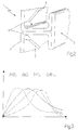
- the characteristics of the pollutant sound wave in fact, vary according to the pollutant sound source (moving vehicles and trains, machinery, etc.), whereas the curve representing attenuation of the incident sound wave as a function of the frequency of the sound-absorbing and/or soundproofing panel is of a given fixed shape (continuous line in Figure 3).
- a panel for acoustic barriers characterized by being defined exclusively by a sheet having, on one of the two lateral surfaces, a number of longitudinal sound-breaking fins parallel to and facing one another, and each for breaking the front of the incident sound wave.
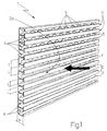
- Number 1 in Figures 1 and 2 indicates as a whole a soundproofing panel particularly suitable for forming acoustic barriers for preventing the propagation of pollutant sound waves in preferably, though not necessarily, open spaces.
- Soundproofing panel 1 is defined by a sheet 2 having, on one of the two lateral surfaces, a number of longitudinal sound-breaking fins 3 parallel to and facing one another, and each for breaking the front F of the incident sound wave.
- sheet 2 is made of metal, such as steel or aluminium, possibly painted and/or zinc plated to withstand atmospheric agents, but may obviously also be made of plastic material or similar.
- Longitudinal sound-breaking fins 3 are T-shaped in section and equally spaced over the whole of lateral surface 2a of sheet 2 to define a number of open gaps 4 for preventing propagation of the incident sound wave, in the same way as currently marketed double glazing. Being located side by side and full of air, in fact, gaps 4 define a layer of air, which simultaneously provides for soundproofing and sound absorption, in the same way as the layer of air trapped between the two panes of glass of a double-glazed window. Gaps 4 also act as sound boxes by more effectively attenuating a given sound frequency spectrum depending on the geometric dimensions of gaps 4.
- sheet 2 has a fretted profile, so that longitudinal sound-breaking fins 3 are defined by the stiffening ribs of sheet 2, and sheet 2 may thus be obtained directly by subjecting a flat rolled section to a succession of rolling, die-forming operations or similar production process.
- sheet 2 preferably, though not necessarily, comprises a number of stiffening drawings 5, which are X-shaped in the example shown, are equally spaced along the back of gaps 4, and provide for increasing the structural rigidity of sheet 2 and the soundproofing capacity of panel 1 by raising the natural resonance frequency of sheet 2.
- drawings 5 may vary to adjust the natural resonance frequency of sheet 2 as required.
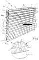
- soundproofing panel 1 also comprises a number of inserts 9 made of soundproofing and/or sound-absorbing material, and each housed inside a respective gap 4 on the panel. Inserts 9 extend the full length of respective gaps 4, may vary in thickness according to their position on soundproofing panel 1, and are all preferably, though not necessarily, made of the same soundproofing and/or sound-absorbing material.
- each insert 9 is retained inside respective gap 4 by a retaining grille 10 inserted inside gap 4, directly over insert 9.
- Each grille on soundproofing panel 1 is obviously fitted between the two longitudinal sound-breaking fins 3 defining respective gap 4, to prevent insert 9 from falling out when soundproofing panel 2 is set up.
- sheet 2 of soundproofing panel 1 also comprises a number of preferably, though not necessarily, semispherical auxiliary drawings 11 appropriately distributed along the back of gaps 4.
- the concavity of each drawing 11 may selectively face inwards or outwards of soundproofing panel 1, i.e. inwards or outwards of respective gap 4, so as to vary the total volume of each gap 4 of soundproofing panel 1 as required.
- the number, depth, shape and arrangement of auxiliary drawings 11 may obviously vary inside each gap 4.
- each gap 4 acts as a sound box for more effectively attenuating a given sound frequency spectrum, depending on the geometric dimensions, i.e. volume, of gap 4.
- FIG. 3 shows, as a function of frequency, the attenuation curve A 0 (f) of a conventional panel (continuous line), and the attenuation curves A 1 (f), A 2 (f), A 3 (f) of three different geometric configurations of soundproofing panel 1 (dash lines).
- Attenuation curve A(f) may obviously also be adjusted using different soundproofing and/or sound-absorbing materials for inserts 9.
- soundproofing panel 1 it is now possible to produce acoustic barriers specially designed to attenuate the sound waves generated by specific pollutant sound sources. This may obviously also be achieved using adjacent soundproofing panels 1 with appropriately differing attenuation curves.
- a further advantage of soundproofing panel 1 as described and illustrated above lies in it being much cheaper to produce than currently used panels, by having no sound-absorbing filler material.
Landscapes
- Engineering & Computer Science (AREA)
- Architecture (AREA)
- Civil Engineering (AREA)
- Structural Engineering (AREA)
- Building Environments (AREA)
- Devices Affording Protection Of Roads Or Walls For Sound Insulation (AREA)
- Soundproofing, Sound Blocking, And Sound Damping (AREA)
Abstract
Description
Claims (13)
- A soundproofing panel (1) for acoustic barriers, characterized by being defined exclusively by a sheet (2) having, on one of the two lateral surfaces, a number of longitudinal sound-breaking fins (3) parallel to and facing one another, and each for breaking the front of the incident sound wave.
- A soundproofing panel as claimed in Claim 1, characterized in that said longitudinal sound-breaking fins (3) are distributed along the whole lateral surface (2a) of the sheet (2) so as to define a number of open, side by side gaps (4) preventing propagation of the incident sound wave.
- A soundproofing panel as claimed in Claim 2, characterized in that said longitudinal sound-breaking fins (3) have a T-shaped section.
- A soundproofing panel as claimed in any one of the foregoing Claims, characterized in that said sheet (2) has a fretted profile, so that said longitudinal sound-breaking fins (3) are defined by the stiffening ribs of the sheet (2).
- A soundproofing panel as claimed in any one of the foregoing Claims, characterized in that said sheet (2) comprises a number of stiffening drawings (5) distributed along the back of said gaps (4).
- A soundproofing panel as claimed in Claim 5, characterized in that the dimensions and the distribution of said stiffening drawings (5) on the sheet (2) may vary so as to adjust the natural resonance frequency of said sheet (2).
- A soundproofing panel as claimed in any one of the foregoing Claims, characterized in that said sheet (2) is obtained directly by subjecting a flat rolled section to a succession of rolling operations.
- A soundproofing panel as claimed in any one of the foregoing Claims, characterized in that the dimensions of said longitudinal sound-breaking fins (3) and the distribution of said longitudinal sound-breaking fins (3) on the lateral surface (2a) of said sheet (2) may vary to adapt the attenuation curve of said panel (1) to the characteristics of the incident sound wave.
- A soundproofing panel as claimed in any one of the foregoing Claims, characterized in that said sheet (2) is made of metal.
- A soundproofing panel as claimed in any one of the foregoing Claims, characterized by comprising a number of inserts (9) made of soundproofing and/or sound-absorbing material, and each housed inside a respective gap (4) on said panel.
- A soundproofing panel as claimed in Claim 10, characterized by comprising a number of retaining grilles (10), each inserted inside a respective gap (4), directly over the corresponding insert (9), so as to retain the insert (9) inside said gap (4).
- A soundproofing panel as claimed in any one of the foregoing Claims, characterized in that said sheet (2) comprises a number of auxiliary drawings (11) appropriately distributed at the back of said gaps (4); the concavity of each of said auxiliary drawings (11) selectively facing inwards or outwards of the corresponding gap (4) to adjust the total volume of each gap (4) on the soundproofing panel (1) as required.
- A soundproofing panel as claimed in Claim 12, characterized in that the number, depth, shape and distribution of said auxiliary drawings (11) may vary inside each gap (4) on said soundproofing panel (1).
Applications Claiming Priority (6)
| Application Number | Priority Date | Filing Date | Title |
|---|---|---|---|
| ITBO990394 | 1999-07-14 | ||
| IT99BO000394 IT1309335B1 (en) | 1999-07-14 | 1999-07-14 | Attenuation curve of soundproofing panel for acoustic barriers can be adjusted during manufacture |
| ITBO990467 | 1999-09-01 | ||
| IT99BO000467 IT1310457B1 (en) | 1999-09-01 | 1999-09-01 | Attenuation curve of soundproofing panel for acoustic barriers can be adjusted during manufacture |
| ITBO990557 | 1999-10-15 | ||
| IT99BO000557 IT1311098B1 (en) | 1999-10-15 | 1999-10-15 | Attenuation curve of soundproofing panel for acoustic barriers can be adjusted during manufacture |
Publications (2)
| Publication Number | Publication Date |
|---|---|
| EP1069243A2 true EP1069243A2 (en) | 2001-01-17 |
| EP1069243A3 EP1069243A3 (en) | 2001-06-06 |
Family
ID=27273906
Family Applications (1)
| Application Number | Title | Priority Date | Filing Date |
|---|---|---|---|
| EP00115350A Withdrawn EP1069243A3 (en) | 1999-07-14 | 2000-07-14 | Soundproofing panel for acoustic barriers |
Country Status (6)
| Country | Link |
|---|---|
| EP (1) | EP1069243A3 (en) |
| AR (1) | AR029380A1 (en) |
| CA (1) | CA2314165A1 (en) |
| IL (1) | IL137249A0 (en) |
| MX (1) | MXPA00006895A (en) |
| TR (1) | TR200002066A3 (en) |
Cited By (4)
| Publication number | Priority date | Publication date | Assignee | Title |
|---|---|---|---|---|
| KR100507755B1 (en) * | 2003-04-25 | 2005-08-10 | 이근식 | A trap type soundproof plate |
| CN109192190A (en) * | 2018-09-19 | 2019-01-11 | 中国人民解放军国防科技大学 | A thin-layer metamaterial sound-absorbing structure |
| CN111749151A (en) * | 2019-03-29 | 2020-10-09 | 比亚迪股份有限公司 | Acoustic panels, sound barriers and track systems |
| CN116516856A (en) * | 2023-04-27 | 2023-08-01 | 武汉理工大学 | Array type vibration-damping noise-reducing barrier plate and assembly method thereof |
Family Cites Families (4)
| Publication number | Priority date | Publication date | Assignee | Title |
|---|---|---|---|---|
| DK142710B (en) * | 1977-11-10 | 1980-12-29 | Elektronikcentralen | Sound absorbing structure. |
| CH641228A5 (en) * | 1979-09-11 | 1984-02-15 | Gysi Gebr Ag | Sound-absorbing element which can be mounted on a load-bearing structure |
| EP0786759A4 (en) * | 1994-10-11 | 1999-12-22 | Nitto Boseki Co Ltd | MUFFLER BODY, MUFFLER PLATE AND MUFFLER UNIT |
| IT1286776B1 (en) * | 1996-11-19 | 1998-07-17 | Fracasso Metalmeccanica | ANTI-ACOUSTIC PANEL |
-
2000
- 2000-07-10 IL IL13724900A patent/IL137249A0/en unknown
- 2000-07-13 CA CA002314165A patent/CA2314165A1/en not_active Abandoned
- 2000-07-13 AR ARP000103589A patent/AR029380A1/en unknown
- 2000-07-13 MX MXPA00006895A patent/MXPA00006895A/en unknown
- 2000-07-13 TR TR2000/02066A patent/TR200002066A3/en unknown
- 2000-07-14 EP EP00115350A patent/EP1069243A3/en not_active Withdrawn
Cited By (6)
| Publication number | Priority date | Publication date | Assignee | Title |
|---|---|---|---|---|
| KR100507755B1 (en) * | 2003-04-25 | 2005-08-10 | 이근식 | A trap type soundproof plate |
| CN109192190A (en) * | 2018-09-19 | 2019-01-11 | 中国人民解放军国防科技大学 | A thin-layer metamaterial sound-absorbing structure |
| CN109192190B (en) * | 2018-09-19 | 2020-05-08 | 中国人民解放军国防科技大学 | Thin-layer metamaterial sound absorption structure |
| CN111749151A (en) * | 2019-03-29 | 2020-10-09 | 比亚迪股份有限公司 | Acoustic panels, sound barriers and track systems |
| CN111749151B (en) * | 2019-03-29 | 2022-01-07 | 比亚迪股份有限公司 | Sound insulation panel, sound barrier and rail system |
| CN116516856A (en) * | 2023-04-27 | 2023-08-01 | 武汉理工大学 | Array type vibration-damping noise-reducing barrier plate and assembly method thereof |
Also Published As
| Publication number | Publication date |
|---|---|
| TR200002066A2 (en) | 2001-02-21 |
| CA2314165A1 (en) | 2001-01-14 |
| AR029380A1 (en) | 2003-06-25 |
| MXPA00006895A (en) | 2004-10-28 |
| TR200002066A3 (en) | 2001-02-21 |
| IL137249A0 (en) | 2001-07-24 |
| EP1069243A3 (en) | 2001-06-06 |
Similar Documents
| Publication | Publication Date | Title |
|---|---|---|
| EP0341057B1 (en) | Sound absorption barriers | |
| US5268540A (en) | Sound barrier absorption panel | |
| EP0750777A1 (en) | Foil sound absorber | |
| CN213038228U (en) | Sound absorbing element barrier for wide-tone noise | |
| KR19990035296U (en) | Soundproofing Panel | |
| EP1069243A2 (en) | Soundproofing panel for acoustic barriers | |
| EP4276244A1 (en) | Acoustic barrier device and acoustic barrier for railway lines | |
| GB2305451A (en) | Noise barrier sytem | |
| KR100400886B1 (en) | Sound absorption type soundproofing panel | |
| JP4233992B2 (en) | Mounting structure of the sound absorbing panel on the back of the sound barrier | |
| JP2000148158A (en) | Slit structure sound absorbing panel | |
| RU2173372C2 (en) | Acoustical panel of noise shield | |
| KR200380479Y1 (en) | Soundproof tunnel | |
| KR102378580B1 (en) | An aluminium ceiling panel | |
| JPH1025712A (en) | Acoustic absorption panel | |
| JP2831562B2 (en) | Noise barrier | |
| EP3555370B1 (en) | Sound-absorbing construction component having extinguishing profiles and sound protection wall | |
| KR102585134B1 (en) | Transparent soundproof panel of sound absorption with hole bonded color micromesh | |
| KR100505844B1 (en) | Soundproof panel | |
| KR200208807Y1 (en) | Soundproof wall | |
| JP3870277B2 (en) | Soundproof panel mounting structure | |
| KR200298070Y1 (en) | Soundproofing | |
| ITBO990557A1 (en) | SOUND INSULATION PANEL FOR ACOUSTIC BARRIERS. | |
| ITBO990394A1 (en) | SOUND INSULATION PANEL FOR ACOUSTIC BARRIERS. | |
| KR910001951B1 (en) | Sound proof wall |
Legal Events
| Date | Code | Title | Description |
|---|---|---|---|
| PUAI | Public reference made under article 153(3) epc to a published international application that has entered the european phase |
Free format text: ORIGINAL CODE: 0009012 |
|
| AK | Designated contracting states |
Kind code of ref document: A2 Designated state(s): AT BE CH CY DE DK ES FI FR GB GR IE IT LI LU MC NL PT SE |
|
| AX | Request for extension of the european patent |
Free format text: AL;LT;LV;MK;RO;SI |
|
| PUAL | Search report despatched |
Free format text: ORIGINAL CODE: 0009013 |
|
| AK | Designated contracting states |
Kind code of ref document: A3 Designated state(s): AT BE CH CY DE DK ES FI FR GB GR IE IT LI LU MC NL PT SE |
|
| AX | Request for extension of the european patent |
Free format text: AL;LT;LV;MK;RO;SI |
|
| 17P | Request for examination filed |
Effective date: 20011205 |
|
| AKX | Designation fees paid |
Free format text: AT BE CH CY DE DK ES FI FR GB GR IE IT LI LU MC NL PT SE |
|
| STAA | Information on the status of an ep patent application or granted ep patent |
Free format text: STATUS: THE APPLICATION IS DEEMED TO BE WITHDRAWN |
|
| 18D | Application deemed to be withdrawn |
Effective date: 20040203 |