EP1069226A1 - Sewing machine needle with improved loop formation - Google Patents
Sewing machine needle with improved loop formation Download PDFInfo
- Publication number
- EP1069226A1 EP1069226A1 EP00106095A EP00106095A EP1069226A1 EP 1069226 A1 EP1069226 A1 EP 1069226A1 EP 00106095 A EP00106095 A EP 00106095A EP 00106095 A EP00106095 A EP 00106095A EP 1069226 A1 EP1069226 A1 EP 1069226A1
- Authority
- EP
- European Patent Office
- Prior art keywords
- needle
- eye
- thread
- tip
- needle according
- Prior art date
- Legal status (The legal status is an assumption and is not a legal conclusion. Google has not performed a legal analysis and makes no representation as to the accuracy of the status listed.)
- Granted
Links
Images


Classifications
-
- D—TEXTILES; PAPER
- D05—SEWING; EMBROIDERING; TUFTING
- D05B—SEWING
- D05B85/00—Needles
Definitions
- the invention relates to a needle, in particular for mechanical insertion of a thread into the material.
- a tufting needle for known the carpet manufacture, which serves a staple fiber yarn to pierce through a base fabric and with the To form staple yarn loops.
- the tufting needle for this purpose has an approximately cylindrical shaft which is pointed at one end. Is near the top a funnel-shaped eye is formed at an angle to the central axis of the needle.
- An air duct is provided in the tufting needle with which the eye can be pressurized with compressed air.
- the shaft is on the clamping side cylindrical and conical towards the tip. The inclination of the eye to the longitudinal axis is approximately 30 °.
- Another tufting needle is known from EP 0187925. This starts from a tubular body, which is cut obliquely to form a tip. On the opposite side of the slope is the tubular one Basic body also opened so that a through the open interior running thread at the slant arranged mouth surface of the tubular base body can leak. The eye thus formed has an oval Cross-section due to the tubular base body given deformation changes along the eye. On the open side of the tubular body opposite side is the tubular base body flattened so that an indentation or groove is formed is.
- Another tufting needle is from DE 2834738 C2 known.
- This needle has a flat needle body Cross-section based on one embodiment almost unchanged to an eye that extends across directed to the longitudinal axis of the needle and elongated oval is.
- a gutter leads to the eye, which is considerable is flatter than the thread.
- the length of the eye is at this Embodiment about the size of the mouth of the eye on the two corresponding opposite one another Needle sides.
- FIG. 5 of the patent specification is a tufting needle with an approximately spoon-shaped Head known.
- a thread groove extends along the shaft, whose depth is less than the thread thickness and essential is less than the eye width.
- the eye is oval trained and extends across the tufting needle.
- On the opposite side of the thread gutter is in Area of the eye and a subsequent shaft area a deflection is provided.
- From DE-OS 2412062 is also a sewing needle known to interact with a thread gripper is set up.
- the sewing needle serves the upper thread to pierce through the material, the forming The loop is then held and enlarged by a thread gripper becomes.
- the sewing needle has a shaft with a thread groove whose depth is slightly greater than that smallest eye diameter so that the thread is completely in the thread trough runs.
- the eye extends on one arcuate path across the needle and expanding thereby funnel-shaped.
- the ear cross-section is fixed oval.
- a trough is provided for the hook or gripper, who works with the needle.
- the needle according to the invention has a long thread well-leading eye and one adjacent to the eye exit Hump to clamp the thread in the material.
- the eye is through a preferably straight passage formed at an acute angle against the longitudinal direction of the needle is inclined. This results in a low friction of the through the eye of running thread on the eye and a good one Thread guidance.
- the thread is pulled back through the eye of the needle and thus a contraction of the needle during the puncturing process generated thread loop avoided.
- the needle according to the invention can therefore produce a loop which, when retracting the needle in its ideal full training is maintained.
- the stake a gripper that holds the sling is not required. This makes it possible to thread even thicker ones Just stab textile.
- E.g. can several Layers of material, e.g. Carbon fiber mats to be fixed. It then only one upper thread without bobbin thread is used.
- the height of the mats can be up to 40mm or more and does not have to be constant. This is the case, for example, with aircraft wings made of laminate material.
- Another advantage is the elimination of the knotting process.
- the gripper is superfluous. This will the thread is spared. Only the required amount of thread is running through the eye.
- one Lockstitch process with each loop formation longer thread lengths to pull through the eye to by means of a gripper pass the loop around a bobbin case to be able to. The hook therefore pulls a thread length through the eye, which then when tightening (knotting) the Upper thread is withdrawn again. Run this way Thread sections often in the conventional sewing process through the eye until it is finally part of the seam to the Come calm.
- the needle according to the invention allows this to be avoided such a thread load.
- the needle according to the invention can be stable be formed. It is not a groove for a gripper required. Accordingly, the otherwise existing one is dropped Cross-sectional weakening.
- the needle according to claim 2 provides the same advantages.
- the opening of the eye extends with a pointed one Angle through the needle body and thereby becomes relative long.
- the circular cross-section gives a good one Thread guide and the thread is stabilized.
- Needle for inserting thread into the material and forming loops, ideally in full training on the return stroke is preserved if the eye is in one very acute angle to the longitudinal direction of the needle is. If the input and the output of the ⁇ hrs are axially offset from each other, so that from Viewed from the side, the entrance and exit of the Do not overlap the needle (i.e. a positive one remains Axial distance between the entrance and exit of the eye) the thread is a good guide and runs with less Friction through the eye. Thus a thread take with the Needle return stroke avoided.
- the eye is preferably cylindrical, what also serves the stated purpose.
- the thread guide It is also useful to have the largest possible eye length, whereby the Length L of the eye is preferably greater than the thickness of the Needle.
- a groove on the shaft leading to the eye enables the thread guide and the almost frictionless drawing of thread into the material when the depth of the gutter approximately matches or is larger than the eye diameter than this.
- the thread channel can be a rectangular, have square or other cross-section.
- the eye is at the entrance of the thread gutter remote side preferably bounded by an edge, the (somewhat rounded and) on the outside of the needle is arranged.
- the edge serves to guide the thread during the needle return stroke and prevents friction between the thread and the sewing material. This will take you away of the thread avoided by the needle during the return stroke.
- the acute angle with which the eye against the longitudinal direction of the needle is preferably smaller than 30 °. Even better, it is below 20 °, preferably below 15 °.
- the distance it is also considered appropriate to use the distance to set a value between the tip and the eye which is less than the length of the eye.
- the comparatively large eye length results in good thread guidance and the comparatively small distance between the tips and eye exit results in a large penetration depth of the thread. This is especially true if the distance between the Tip and the eye exit is less than half the eye length.
- the one provided in the vicinity of the exit of the eye Bump used to clamp the thread in or on the Serves material preferably has a height that at about 80% of the diameter of the eye. In this way the thread is held firmly in the stitch hole, without increasing the friction too much. It results also a small compared to a hollow needle Taphole. This is, for example, for stapling or stabilizing of carbon fiber mats an advantage.
- the cusp is also considered beneficial to keep relatively short in the longitudinal direction of the needle, whereby it is preferably shorter than 80% of the length of the eye.
- hump and the eye is preferably one rounded transition trained. It can also be used for sensitive Threads are processed gently. In particular Kevlar threads can be inserted without damage.
- a long straight one, essentially constant Cross-section shaft allows piercing of threads even in thick layers of material. E.g. can with the needle according to the invention through several layers of material Plunging should be fixed, the layers not being punctured Need to become.
- Figure 1 is a needle 1 for piercing a thread 2 illustrated in material 3 ( Figures 7 to 12).
- the Needle 1 has a shaft 4, which at one end in a Clamping part 5 and at its other, free end in one Head 6 merges.
- the head 6 contains an eye 7 with the length L, the details of which can be seen in particular from FIGS. 2 and 3 emerge.
- the eye 7 is formed by a cylindrical bore 8, whose central axis 9 at an acute angle of approximately 13 ° to a direction determining the longitudinal direction of the shaft Longitudinal central axis 11 of the needle 1 stands.
- the eye 7 or the bore 8 has an input 12 and an output 14 on.
- the entrance 12 is relative to the longitudinal direction the needle 1 by a near-tip boundary or Edge 15 and a distant boundary or edge 16 limited.
- Between the bore 8 and the needle side 36, which is assigned to the thread trough 27 results in a material area 15a, the cross section of which starts from the Edge 15 increases towards the tip 21.
- An extension the bore 8, which touches the edge 15, results in the Needle side 36 an imaginary intersection 35. The distance between this intersection 35 and the bottom 28 of the needle groove 27 is larger than the bore diameter.
- the exit 14 is through a near edge 17 and delimits a distal edge 18.
- the entrance 12 and the output 14 are with respect to the axial direction of the Needle 1 spaced apart, i.e. between the edge 15 and the edge 18 there is a positive distance.
- the input 12 and the output 14 overlap not, i.e. they are in axially different places arranged.
- the needle 1 Approximately in the area of the opening 14 begins Taper head 6 of needle 1 to a tip 21. In near the tip 21 the needle 1, as illustrated in FIG. 4, a circular cross section. The Tip 21 sets the position of the longitudinal central axis 11 firmly. The tip-side edge 17 lies with respect to this of the output 14 on a different side than the distal one Edge 16 of the entrance 12. Despite a slight incline the bore 8 extends against the longitudinal central axis 11 completely from one side of the longitudinal central axis 11 the other.
- the bore 8 has a circular cross section on and is cylindrical.
- the distance between the tips Edge 17 of the exit 14 and the tip 21 is preferably at most as large as the needle size and thus significantly shorter than the length of the bore 8.
- the bore 8 goes at its edge 18 remote from the tip with a curve into a hump 22 that extends from a back 23 defined by the shaft 4 extends away.
- the height of the hump 22 is preferably too set about 80% of the diameter of the bore 8.
- the bump 22 preferably has a short straight line Section 24, which has a rounding in one against the
- the longitudinal central axis 11 passes over the inclined region 25 which the eye 7 connects.
- At the distance from the eye 7 Section 24 merges into an area 26 which is inclined against the longitudinal central axis 11. The transitions are rounded in each case.
- a thread groove 27 formed, which are from the clamping part 5 to extends to the entrance 12 of the eye 7.
- the thread groove 27 has, as shown in Figure 6, an approximately square Cross section on.
- the thread groove 27 is almost sufficient up to the longitudinal central axis 11 of the shaft 4, the rest also preferably a substantially square one Has cross section. Only in the area of the hump 22, the cross section is approximately rectangular, wherein the corners, i.e. the longitudinal edges of the shaft 4 continuously are rounded.
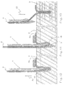
- FIG. 7 to 9 is the piercing of the thread 2 illustrated by the sewing material 3 in different working stages.
- Figure 7 shows the sewing material 3, for example. through several layers of mats on top of each other, For example, carbon fiber mats can be formed with a finished trained loop 31.
- the needle 1 has lengthways of the sewing material 3 moves one step further and is now in the direction indicated by an arrow 32 on the Material 3 too moved.
- the needle 1 opens with the tip 21 a stitch hole and pierces the sewing material 3.
- FIG. 8 illustrates, the thread lying on the sewing material 3 2a are fixed by a holder 33.
- the needle 1 pulls on the downward stroke with her eye 7 by means of the rounded Edge 18 thread 2 through the open stitch hole, the thread 2 runs with little friction in the thread groove 27.
- the hump 22 also fixes the thread 2 to the material to be sewn and prevents stabs that are already sticking to the material 3 Thread 2a is drawn.
- the hump 22 presses thread 2 to the wall of the taphole, i.e. to the Material 3 on.
- the loop 31 formed remains free stand below the material 3.
- the thread is free of play in the eye 7 and in the thread groove 27. It runs essentially stretched through the eye 7, being round, in the thread running direction inclined hole 8 the thread a certain Gives stability.
- the edge 15 moves the thread 2 in Direction of the eye 7 and prevents contact between the thread 2 and the sewing material 3. This promotes loop formation the needle of the invention 1.
- the thread 2 forming the loop 31 passes through eye 7 only once.
- the loop 31 is finished several layers of material are stabilized.
- the needle according to the invention enables this a controlled loop formation.
- FIGS. 10 to 12 the thread 2 is pierced illustrates a thicker sewing material 3, the needle 1 is not punctured. Otherwise the puncture process is correct largely with the process described above. However, no loops or loops are under the sewing material 3, but the pierced Thread 2 gets stuck in the stitch hole. That state is in Figure 10 for a previous puncture illustrated.
- the needle 1 begins in FIG. 10 with a Puncture direction according to arrow 32 a new stitching process. This is illustrated below in FIG. 11. How visible, the eye 7 pulls by means of the rounded edge 18 the thread 2 into the sewing material 3.
- the thread remains 2 stuck in the tap hole by holding it frictionally is. The comparatively lower friction between the thread 2 and the needle 1 allows them from the The stitch hole is pulled out in the direction of arrow 34, without taking the thread 2.
- a needle for inserting or piercing a thread 2 in or by sewing material 3 has a preferably cylindrical, inclined flat against the longitudinal direction of the needle long eye with a hump on the thread exit side is adjacent. This is used to clamp one in the material stitched thread in the stitch hole.
- a needle 1 with such a structure allows a good low-friction Guiding the thread 2, so that loop formation without additional Gripper is possible.
Landscapes
- Engineering & Computer Science (AREA)
- Textile Engineering (AREA)
- Sewing Machines And Sewing (AREA)
Abstract
Description
Die Erfindung betrifft eine Nadel, insbesondere zum maschinellen Einstechen eines Fadens in Nähgut.The invention relates to a needle, in particular for mechanical insertion of a thread into the material.
Beim Nähen von Nähgut wird ein Faden, der sogenannte Oberfaden, mittels einer Nadel, die in der Nähe ihrer Spitze mit einem Öhr versehen ist, fortlaufend durch das Nähgut gestochen. Beim jeweiligen Zurückziehen der Nadel ergibt sich eine Schlinge, die von einem Schlingengreifer erfasst und durch die ein weiterer Faden, der sogenannte Unterfaden, gezogen wird. Es entsteht eine aus Ober- und Unterfaden bestehende Naht. Um den Unterfaden durch die Schlinge ziehen zu können, wird die Schlinge mit dem Schlingengreifer erfasst und vergrößert, um sie um eine Spulenkapsel herumzuziehen, in der sich der Unterfaden befindet. Dazu wird vorn Schlingegreifer zunächst Oberfaden nachgezogen, der dann durch das Öhr wieder zurückgezogen wird. Der Oberfaden durchläuft deshalb das Öhr der Nadel vielmals und wird dadurch stark beansprucht.When sewing material, a thread, the so-called Upper thread, by means of a needle that is close to her Is provided with an eye, continuously through the Stitched material. Each time the needle is withdrawn results in a noose by a noose gripper captured and through which another thread, the so-called Bobbin thread. One arises from upper and Existing thread. To the bobbin thread through the To be able to pull the noose, the noose is with the Loop gripper grasped and enlarged by one Pull the bobbin case around, in which the bobbin thread located. For this purpose, the loop hook is first upper thread tightened, which then pulled back through the eye becomes. The upper thread therefore passes through the eye of the needle many times and is heavily used.
Darüber hinaus existieren Nähvorgänge, bei denen der Oberfaden in oder durch das Nähgut gestochen wird, ohne dass ein Greifer den Faden und die sich bildende Schlinge beim Zurückziehen der Nadel festhält. Soll sich hier zuverlässig eine Schlinge bilden, muss der Faden durch Reibung zwischen ihm und dem Nähgut gehalten werden.In addition, there are sewing processes in which the Upper thread is stuck in or through the material without that a gripper the thread and the loop formed holds when pulling back the needle. Should be reliable here form a loop, the thread must be rubbed be held between him and the material.
Aus der US-PS 3.523.510 ist eine Tufting-Nadel für die Teppichherstellung bekannt, die dazu dient, ein Stapelfasergarn durch ein Grundgewebe zu stechen und mit dem Stapelfasergarn Schlingen auszubilden. Die Tuftingnadel weist dazu einen etwa zylindrischen Schaft auf, der an einem Ende zugespitzt ist. In der Nähe der Spitze ist schräg zur Nadelmittelachse ein trichterförmiges Öhr ausgebildet. In der Tuftingnadel ist ein Luftkanal vorgesehen mit dem das Öhr mit Druckluft beaufschlagbar ist. Im Anschluss an das Öhr sind an beiden einander gegenüberliegenden Seiten der Tuftingnadel flache Rinnen ausgebildet, deren Tiefe geringer ist als der kleinste Durchmesser des Öhrs. Im Anschluss an das Öhr ist der Schaft zur Einspannseite hin zylindrisch und zur Spitze hin kegelförmig ausgebildet. Die Neigung des Öhrs zur Längsachse beträgt etwa 30°. From US-PS 3,523,510 is a tufting needle for known the carpet manufacture, which serves a staple fiber yarn to pierce through a base fabric and with the To form staple yarn loops. The tufting needle for this purpose has an approximately cylindrical shaft which is pointed at one end. Is near the top a funnel-shaped eye is formed at an angle to the central axis of the needle. An air duct is provided in the tufting needle with which the eye can be pressurized with compressed air. In connection at the eye are opposite each other on both Flat channels formed on the sides of the tufting needle, whose depth is less than the smallest diameter of the Öhrs. Following the eye, the shaft is on the clamping side cylindrical and conical towards the tip. The inclination of the eye to the longitudinal axis is approximately 30 °.
Die Schlingenbildung wird bei dieser Nadel durch die Wirkung der in das Öhr eingeführten Druckluft unterstützt. Andere Mittel zum Festhalten der Fadenschlinge sind nicht ersichtlich.The loop formation is with this needle by the Effect of the compressed air introduced into the eye supports. There are no other means of holding the thread loop evident.
Eine weitere Tuftingnadel ist aus der EP 0187925 bekannt. Diese geht von einem rohrförmigen Grundkörper aus, der zur Ausbildung einer Spitze schräg abgeschnitten ist. An der der Schräge gegenüberliegenden Seite ist der rohrförmige Grundkörper ebenfalls geöffnet, so dass ein durch den geöffneten Innenraum laufender Faden an der schräg angeordneten Mündungsfläche des rohrförmigen Grundkörpers austreten kann. Das so gebildete Öhr weist einen ovalen Querschnitt auf, der infolge einer dem rohrförmigen Grundkörper erteilten Deformation entlang des Öhrs wechselt. Auf der der offenen Seite des rohrförmigen Grundkörpers gegenüberliegenden Seite ist der rohrförmige Grundkörper abgeflacht, so dass eine Einbuchtung oder Hohlkehle ausgebildet ist.Another tufting needle is known from EP 0187925. This starts from a tubular body, which is cut obliquely to form a tip. On the opposite side of the slope is the tubular one Basic body also opened so that a through the open interior running thread at the slant arranged mouth surface of the tubular base body can leak. The eye thus formed has an oval Cross-section due to the tubular base body given deformation changes along the eye. On the open side of the tubular body opposite side is the tubular base body flattened so that an indentation or groove is formed is.
Eine weitere Tuftingnadel ist aus der DE 2834738 C2 bekannt. Diese Nadel weist einen Nadelgrundkörper mit flachem Querschnitt auf, der sich in einer Ausführungsform nahezu unverändert bis zu einem Öhr erstreckt, das quer zur Längsachse der Nadel gerichtet und länglich oval ausgebildet ist. Zu dem Öhr führt eine Rinne, die erheblich flacher ist als der Faden. Die Länge des Öhrs ist bei dieser Ausführungsform etwa so groß wie die Mündung des Öhrs an den beiden entsprechenden einander gegenüberliegenden Nadelseiten.Another tufting needle is from DE 2834738 C2 known. This needle has a flat needle body Cross-section based on one embodiment almost unchanged to an eye that extends across directed to the longitudinal axis of the needle and elongated oval is. A gutter leads to the eye, which is considerable is flatter than the thread. The length of the eye is at this Embodiment about the size of the mouth of the eye on the two corresponding opposite one another Needle sides.
Bei einer abgewandelten, aus der genannten DE 2834738 C2 vorbekannten, Ausführungsform (Figur 5 der Patentschrift) ist eine Tuftingnadel mit ungefähr löffelförmigem Kopf bekannt. Entlang des Schafts erstreckt sich eine Fadenrinne, deren Tiefe geringer als die Fadendicke und wesentlich geringer als die Öhrbreite ist. Das Öhr ist oval ausgebildet und erstreckt sich quer durch die Tuftingnadel. An der der Fadenrinne gegenüberliegenden Seite ist im Bereich des Öhrs und eines sich anschließenden Schaftbereichs eine Ausbiegung vorgesehen.In a modified, from the mentioned DE 2834738 C2 previously known embodiment (FIG. 5 of the patent specification) is a tufting needle with an approximately spoon-shaped Head known. A thread groove extends along the shaft, whose depth is less than the thread thickness and essential is less than the eye width. The eye is oval trained and extends across the tufting needle. On the opposite side of the thread gutter is in Area of the eye and a subsequent shaft area a deflection is provided.
Ähnliche Tuftingnadeln gehen aus der DE 3002345 C2, der US-PS 4.502.403 und der US-PS 4.233.917 hervor.Similar tufting needles can be found in DE 3002345 C2, U.S. Patent 4,502,403 and U.S. Patent 4,233,917.
Aus der DE-OS 2412062 ist darüber hinaus eine Nähnadel bekannt, die zum Zusammenwirken mit einem Fadengreifer eingerichtet ist. Die Nähnadel dient dazu, den Oberfaden durch das Nähgut zu stechen, wobei die sich bildende Schlinge dann von einem Fadengreifer gehalten und vergrößert wird. Die Nähnadel weist einen Schaft mit einer Fadenrinne auf, deren Tiefe geringfügig größer ist als der kleinste Öhrdurchmesser, so dass der Faden vollständig in der Fadenrinne läuft. Das Öhr erstreckt sich auf einem bogenförmigen Weg quer durch die Nadel und erweitert sich dabei trichterförmig. Der Öhrquerschnitt ist oval festgelegt. Unmittelbar anschließend an das Öhr ist an der von der Spitze abgewandten und der Fadenrinne gegenüberliegenden Seite eine Mulde für den Haken oder Greifer vorgesehen, der mit der Nadel zusammenarbeitet.From DE-OS 2412062 is also a sewing needle known to interact with a thread gripper is set up. The sewing needle serves the upper thread to pierce through the material, the forming The loop is then held and enlarged by a thread gripper becomes. The sewing needle has a shaft with a thread groove whose depth is slightly greater than that smallest eye diameter so that the thread is completely in the thread trough runs. The eye extends on one arcuate path across the needle and expanding thereby funnel-shaped. The ear cross-section is fixed oval. Immediately after the eye is at the of facing away from the tip and opposite the thread groove A trough is provided for the hook or gripper, who works with the needle.
Hiervon ausgehend ist es Aufgabe der Erfindung, eine Nadel mit verbesserter Schlingenbildung zu schaffen.Proceeding from this, it is an object of the invention to To create a needle with improved looping.
Diese Aufgabe wird mit einer Nadel gelöst, die die
Merkmale der Patentansprüche 1 oder 2 aufweist. This task is solved with a needle that the
Features of
Die erfindungsgemäße Nadel weist ein langes, den Faden gut führendes Öhr sowie einen dem Öhrausgang benachbarten Höcker zum Festklemmen des Fadens im Nähgut auf. Das Öhr wird durch einen vorzugsweise geraden Durchgang gebildet, der im spitzen Winkel gegen die Nadellängsrichtung geneigt ist. Dies ergibt eine geringe Reibung des durch das Öhr laufenden Fadens an dem Öhr und eine gute Führung des Fadens.The needle according to the invention has a long thread well-leading eye and one adjacent to the eye exit Hump to clamp the thread in the material. The eye is through a preferably straight passage formed at an acute angle against the longitudinal direction of the needle is inclined. This results in a low friction of the through the eye of running thread on the eye and a good one Thread guidance.
In Verbindung mit dem an dem Nadelrücken angeordneten Höcker wird ein Zurückziehen des Fadens durch das Nadelöhr und somit ein Zusammenziehen der von der Nadel beim Einstichvorgang erzeugten Fadenschlinge vermieden. Mit der erfindungsgemäßen Nadel kann deshalb eine Schlinge erzeugt werden, welche beim Zurückziehen der Nadel in ihrer idealerweise vollen Ausbildung erhalten bleibt. Der Einsatz eines Greifers, der die Schlinge festhält, ist nicht erforderlich. Dadurch wird es möglich, auch Fäden in dickere Textilien lediglich einzustechen. Bspw. können mehrere Lagen Material, z.B. Kohlefasermatten, fixiert werden. Es wird dann nur mit einem Oberfaden ohne Unterfaden gearbeitet. Die Höhe der Matten kann bis zu 40mm oder mehr betragen und muss nicht konstant sein. Dies ist bspw. bei Flugzeugtragflächen aus Laminatmaterial der Fall. Hierbei ist von Bedeutung, dass durch diese Art der Stabilisierung ohne Unterfaden die Kohlefasermatten nicht beschädigt werden und dass die Höhe des Nähguts nicht durch eine Verknotung mit einem Unterfaden beeinflusst wird. Dies kann bei einer herkömmlichen Steppstichnaht mit Oberfaden und mit diesem verknoteten Unterfaden nicht sichergestellt werden. Die Verfestigung des durch den Einstichvorgang stabilisierten Schichtmaterials kann, wenn die Matten vorimprägniert sind, durch einen Wärmeprozess erfolgen. Somit können Schlingen gebildet werden, ohne dass das Öhr der Nadel komplett durch das Nähgut sticht.In connection with the arranged on the needle back The thread is pulled back through the eye of the needle and thus a contraction of the needle during the puncturing process generated thread loop avoided. With the The needle according to the invention can therefore produce a loop which, when retracting the needle in its ideal full training is maintained. The stake a gripper that holds the sling is not required. This makes it possible to thread even thicker ones Just stab textile. E.g. can several Layers of material, e.g. Carbon fiber mats to be fixed. It then only one upper thread without bobbin thread is used. The height of the mats can be up to 40mm or more and does not have to be constant. This is the case, for example, with aircraft wings made of laminate material. Here is significant that through this type of stabilization the carbon fiber mats will not be damaged without the bobbin thread and that the height of the sewing material is not due to a knot is influenced with a bobbin thread. This can with a conventional lockstitch seam with upper thread and not ensured with this knotted bobbin thread become. The solidification of the puncture Stabilized layer material can be used if the mats are pre-impregnated are done through a heating process. Consequently can be formed without the eye of the The needle sticks completely through the material.
Ein weiterer Vorteil liegt dem Wegfall des Verknotungsprozess. Der Greifer ist überflüssig. Dadurch wird der Faden geschont. Es läuft lediglich der benötigte Fadenanteil durch das Öhr. Demgegenüber sind bei einem Steppstichvorgang bei jeder Schlingenbildung größere Fadenlängen durch das Öhr zu ziehen, um mittels eines Greifers die gebildete Schlinge um eine Spulenkapsel herumführen zu können. Der Greifer zieht deshalb eine Fadenlänge durch das Öhr, die dann beim Festziehen (Verknoten) des Oberfadens wieder zurückgezogen wird. Auf diese Weise laufen beim herkömmlichen Nähvorgang Fadenabschnitte vielfach durch das Öhr, bis sie letztendlich als Teil der Naht zur Ruhe kommen. Die erfindungsgemäße Nadel gestattet die Vermeidung einer solchen Fadenbelastung.Another advantage is the elimination of the knotting process. The gripper is superfluous. This will the thread is spared. Only the required amount of thread is running through the eye. In contrast, one Lockstitch process with each loop formation longer thread lengths to pull through the eye to by means of a gripper pass the loop around a bobbin case to be able to. The hook therefore pulls a thread length through the eye, which then when tightening (knotting) the Upper thread is withdrawn again. Run this way Thread sections often in the conventional sewing process through the eye until it is finally part of the seam to the Come calm. The needle according to the invention allows this to be avoided such a thread load.
Darüber hinaus kann die erfindungsgemäße Nadel stabil ausgebildet werden. Es ist keine Hohlkehle für einen Greifer erforderlich. Entsprechend entfällt die sonst vorhandene Querschnittsschwächung.In addition, the needle according to the invention can be stable be formed. It is not a groove for a gripper required. Accordingly, the otherwise existing one is dropped Cross-sectional weakening.
Die Nadel nach Anspruch 2 erbringt die gleichen Vorteile.
Die Öffnung des Öhrs erstreckt sich mit einem spitzen
Winkel durch den Nadelkörper und wird dadurch relativ
lang. Der kreisförmige Querschnitt ergibt dabei eine gute
Fadenführung und der Faden wird stabilisiert.The needle according to
Eine besonders gute Eignung der erfindungsgemäßen Nadel zum Einstechen von Faden in Nähgut und Schlingenbildung, welche beim Rückhub in idealerweise voller Ausbildung erhalten bleibt, ergibt sich, wenn das Öhr in einem sehr spitzen Winkel zu der Nadellängsrichtung ausgerichtet ist. Wenn dabei der Eingang und der Ausgang des Öhrs axial gegeneinander versetzt sind, so dass sich aus Seitenrichtung gesehen der Eingang und der Ausgang der Nadel nicht überschneiden (d.h. es verbleibt ein positiver Axialabstand zwischen Eingang und Ausgang des Öhrs), erhält der Faden eine gute Führung und läuft mit geringer Reibung durch das Öhr. Somit wird eine Fadenmitnahme beim Nadelrückhub vermieden.A particularly good suitability of the invention Needle for inserting thread into the material and forming loops, ideally in full training on the return stroke is preserved if the eye is in one very acute angle to the longitudinal direction of the needle is. If the input and the output of the Öhrs are axially offset from each other, so that from Viewed from the side, the entrance and exit of the Do not overlap the needle (i.e. a positive one remains Axial distance between the entrance and exit of the eye) the thread is a good guide and runs with less Friction through the eye. Thus a thread take with the Needle return stroke avoided.
Das Öhr ist vorzugsweise zylindrisch ausgebildet, was ebenfalls dem genannten Zweck dient. Der Fadenführung dienlich ist auch eine möglichst große Öhrlänge, wobei die Länge L des Öhrs vorzugsweise größer ist als die Dicke der Nadel.The eye is preferably cylindrical, what also serves the stated purpose. The thread guide It is also useful to have the largest possible eye length, whereby the Length L of the eye is preferably greater than the thickness of the Needle.
Eine zu dem Öhr führende Rinne an dem Schaft ermöglicht die Fadenführung und das nahezu reibungsfrei Einziehen des Fadens in das Nähgut, wenn die Tiefe der Rinne etwa mit dem Öhrdurchmesser übereinstimmt oder größer ist als dieser. Die Fadenrinne kann dabei einen rechteckigen, quadratischen oder auch anderweitigen Querschnitt aufweisen.A groove on the shaft leading to the eye enables the thread guide and the almost frictionless drawing of thread into the material when the depth of the gutter approximately matches or is larger than the eye diameter than this. The thread channel can be a rectangular, have square or other cross-section.
Das Öhr ist an seinem Eingang an der von der Fadenrinne abliegenden Seite vorzugsweise durch eine Kante begrenzt, die (etwas verrundet und) an der Nadelaußenseite angeordnet ist. Die Kante dient der Fadenführung beim Nadelrückhub und bewirkt eine Vermeidung von Reibung zwischen dem Faden und dem Nähgut. Dadurch wird eine Mitnahme des Fadens durch die Nadel beim Rückhub vermieden. The eye is at the entrance of the thread gutter remote side preferably bounded by an edge, the (somewhat rounded and) on the outside of the needle is arranged. The edge serves to guide the thread during the needle return stroke and prevents friction between the thread and the sewing material. This will take you away of the thread avoided by the needle during the return stroke.
Der spitze Winkel, mit dem das Öhr gegen die Nadellängsrichtung geneigt ist, ist vorzugsweise kleiner als 30°. Besser noch liegt er unter 20°, vorzugsweise unter 15°.The acute angle with which the eye against the longitudinal direction of the needle is preferably smaller than 30 °. Even better, it is below 20 °, preferably below 15 °.
Weiter wird es als zweckmäßig angesehen, den Abstand zwischen der Spitze und dem Öhr auf einen Wert festzulegen, der geringer ist als die Länge des Öhrs. Die vergleichsweise große Öhrlänge ergibt eine gute Fadenführung und der vergleichsweise geringe Abstand zwischen Spitze und Öhrausgang ergibt eine große Einstichtiefe des Fadens. Dies gilt insbesondere, wenn der Abstand zwischen der Spitze und dem Öhrausgang geringer ist als die halbe Öhrlänge.It is also considered appropriate to use the distance to set a value between the tip and the eye which is less than the length of the eye. The comparatively large eye length results in good thread guidance and the comparatively small distance between the tips and eye exit results in a large penetration depth of the thread. This is especially true if the distance between the Tip and the eye exit is less than half the eye length.
Der in Nachbarschaft des Ausgangs des Öhrs vorgesehene Höcker, der zum Festklemmen des Fadens in oder an dem Nähgut dient, weist vorzugsweise eine Höhe auf, die bei etwa 80% des Durchmessers des Öhrs liegt. Auf diese Weise ergibt sich ein gutes Festhalten des Fadens in dem Stichloch, ohne eine zu große Erhöhung der Reibung. Es ergibt sich außerdem im Vergleich zu einer Hohlnadel ein kleines Stichloch. Dies ist bspw. für das Heften bzw. Stabilisieren von Kohlefasermatten von Vorteil.The one provided in the vicinity of the exit of the eye Bump used to clamp the thread in or on the Serves material, preferably has a height that at about 80% of the diameter of the eye. In this way the thread is held firmly in the stitch hole, without increasing the friction too much. It results also a small compared to a hollow needle Taphole. This is, for example, for stapling or stabilizing of carbon fiber mats an advantage.
Außerdem wird es als vorteilhaft angesehen, den Höcker in Nadellängsrichtung relativ kurz zu halten, wobei er vorzugsweise kürzer als 80% der Länge des Öhrs ist.The cusp is also considered beneficial to keep relatively short in the longitudinal direction of the needle, whereby it is preferably shorter than 80% of the length of the eye.
Zwischen dem Höcker und dem Öhr ist vorzugsweise ein verrundeter Übergang ausgebildet. Damit können auch empfindliche Fäden schonend verarbeitet werden. Insbesondere können Kevlarfäden beschädigungsfrei eingestochen werden. Between the hump and the eye is preferably one rounded transition trained. It can also be used for sensitive Threads are processed gently. In particular Kevlar threads can be inserted without damage.
Ein langer gerader, einen im Wesentlichen konstanten Querschnitt aufweisender Schaft ermöglicht das Einstechen von Fäden auch in dicke Nähgutschichten. Bspw. können mit der erfindungsgemäßen Nadel mehrere Lagen Material durch Einstechen fixiert werden, wobei die Lagen nicht durchstochen werden müssen.A long straight one, essentially constant Cross-section shaft allows piercing of threads even in thick layers of material. E.g. can with the needle according to the invention through several layers of material Plunging should be fixed, the layers not being punctured Need to become.
Weitere Einzelheiten von vorteilhaften Ausführungsformen der Erfindung sind Gegenstand der Zeichnung, der Beschreibung oder von Unteransprüchen.Further details of advantageous embodiments the invention are the subject of the drawing, the Description or subclaims.
In der Zeichnung ist ein Ausführungsbeispiel der Erfindung
veranschaulicht. Es zeigen:
In Figur 1 ist eine Nadel 1 zum Einstechen eines Fadens
2 in Nähgut 3 (Figuren 7 bis 12) veranschaulicht. Die
Nadel 1 weist einen Schaft 4 auf, der an einem Ende in ein
Einspannteil 5 und an seinem anderen, freien Ende in einen
Kopf 6 übergeht. Der Kopf 6 enthält ein Öhr 7 mit der Länge
L, dessen Einzelheiten insbesondere aus den Figuren 2
und 3 hervorgehen.In Figure 1 is a
Das Öhr 7 wird durch eine zylindrische Bohrung 8 gebildet,
deren Bohrungsmittelachse 9 in einem spitzen Winkel
von etwa 13° zu einer die Schaftlängsrichtung bestimmenden
Längsmittelachse 11 der Nadel 1 steht. Das Öhr
7 bzw. die Bohrung 8 weist einen Eingang 12 und einen Ausgang
14 auf. Der Eingang 12 wird bezüglich der Längsrichtung
der Nadel 1 durch eine spitzennahe Begrenzung oder
Kante 15 und eine spitzenferne Begrenzung oder Kante 16
begrenzt. Zwischen der Bohrung 8 und der Nadelseite 36,
die der Fadenrinne 27 zugeordnet ist, ergibt sich ein Materialbereich
15a, dessen Querschnitt ausgehend von der
Kante 15 zu der Spitze 21 hin zunimmt. Eine Verlängerung
der Bohrung 8, die die Kante 15 berührt, ergibt mit der
Nadelseite 36 einen gedachten Schnittpunkt 35. Der Abstand
zwischen diesem Schnittpunkt 35 und dem Boden 28 der Nadelrinne
27 ist größer als der Bohrungsdurchmesser.The
Der Ausgang 14 wird durch eine spitzennahe Kante 17
und eine spitzenferne Kante 18 begrenzt. Der Eingang 12
und der Ausgang 14 sind bezüglich der Axialrichtung der
Nadel 1 voneinander beabstandet, d.h. zwischen der Kante
15 und der Kante 18 ist ein positiver Abstand vorhanden.
Der Eingang 12 und der Ausgang 14 überschneiden einander
nicht, d.h. sie sind an axial unterschiedlichen Stellen
angeordnet.The
Ungefähr im Bereich der Öffnung 14 beginnt sich der
Kopf 6 der Nadel 1 zu einer Spitze 21 hin zu verjüngen. In
der Nähe der Spitze 21 weist die Nadel 1, wie Figur 4 veranschaulicht,
einen kreisförmigen Querschnitt auf. Die
Spitze 21 legt dabei die Lage der Längsmittelachse 11
fest. Bezüglich dieser liegt die spitzenseitige Kante 17
des Ausgangs 14 auf einer anderen Seite als die spitzenferne
Kante 16 des Eingangs 12. Trotz geringer Neigung
gegen die Längsmittelachse 11 erstreckt sich die Bohrung 8
vollständig von einer Seite der Längsmittelachse 11 auf
die andere.Approximately in the area of the
Die Bohrung 8 weist einen kreisförmigen Querschnitt
auf und ist zylinderförmig. Der Abstand zwischen der spitzennahen
Kante 17 des Ausgangs 14 und der Spitze 21 ist
vorzugsweise höchstens so groß wie die Nadelstärke und
somit deutlich kürzer als die Länge der Bohrung 8.The
Die Bohrung 8 geht an ihrer spitzenfernen Kante 18
mit einer Rundung in einen Höcker 22 über, der sich von
einem von dem Schaft 4 definierten Rücken 23 weg erstreckt.
Die Höhe des Höckers 22 ist dabei vorzugsweise zu
etwa 80% des Durchmessers der Bohrung 8 festgelegt.The
Der Höcker 22 weist vorzugsweise einen kurzen geraden
Abschnitt 24 auf, der mit einer Rundung in einen gegen die
Längsmittelachse 11 geneigten Bereich 25 übergeht, der an
das Öhr 7 anschließt. An der von dem Öhr 7 abliegenden
Seite geht der Abschnitt 24 in einen Bereich 26 über, der
gegen die Längsmittelachse 11 geneigt ist. Die Übergänge
sind jeweils verrundet.The
An der dem Höcker 22 gegenüberliegenden Schaftseite
ist, wie aus Figur 2 und 3 ersichtlich ist, eine Fadenrinne
27 ausgebildet, die sich von dem Einspannteil 5 bis
zu dem Eingang 12 des Öhrs 7 erstreckt. Die Fadenrinne 27
weist, wie aus Figur 6 hervorgeht, einen etwa quadratischen
Querschnitt auf. Die Fadenrinne 27 reicht dabei fast
bis zu der Längsmittelachse 11 des Schafts 4, der im Übrigen
ebenfalls einen vorzugsweise im Wesentlichen quadratischen
Querschnitt aufweist. Lediglich im Bereich des Höckers
22 ist der Querschnitt ungefähr rechteckig, wobei
die Ecken, d.h. die Längskanten des Schafts 4 durchgehend
verrundet sind.On the shaft side opposite the
Mit der insoweit beschriebenen Nadel 1 wird ein
Einstech- oder Nähvorgang folgendermaßen durchgeführt:With the
In Figur 7 bis 9 ist das Durchstechen des Fadens 2
durch das Nähgut 3 in verschiedenen Arbeitsstadien veranschaulicht.
Figur 7 zeigt dabei das Nähgut 3, das bspw.
durch mehrere Schichten übereinanderliegender Matten,
bspw. Kohlefasermatten, gebildet sein kann, mit einer fertig
ausgebildeten Schlinge 31. Die Nadel 1 hat sich längs
des Nähguts 3 einen Schritt weiterbewegt und wird nun in
der durch einen Pfeil 32 bezeichneten Richtung auf das
Nähgut 3 zu bewegt. Mit der Spitze 21 öffnet die Nadel 1
ein Stichloch und durchsticht das Nähgut 3. Wie Figur 8
veranschaulicht, kann der auf dem Nähgut 3 liegende Faden
2a dabei durch einen Halter 33 fixiert werden. Die Nadel 1
zieht beim Abwärtshub mit ihrem Öhr 7 mittels der verrundeten
Kante 18 den Faden 2 durch das geöffnete Stichloch,
wobei der Faden 2 reibungsarm in der Fadenrinne 27 läuft.
Auch der Höcker 22 fixiert den Faden 2 an dem Nähgut und
verhindert, dass bereits auf dem Nähgut 3 liegender, eingestochender
Faden 2a nachgezogen wird.7 to 9 is the piercing of the
Beim Rückhub der Nadel 1 in der in Figur 9 durch einen
Pfeil 34 bezeichneten Richtung, drückt der Höcker 22
den Faden 2 an die Wandung des Stichlochs, d.h. an das
Nähgut 3 an. Die gebildete Schlinge 31 bleibt dabei frei
unterhalb des Nähguts 3 stehen. Der Faden liegt spielfrei
in dem Öhr 7 und in der Fadenrinne 27. Er läuft im Wesentlichen
gestreckt durch das Öhr 7, wobei die runde, in Fadenlaufrichtung
geneigte Bohrung 8 dem Faden eine gewisse
Stabilität verleiht. Die Kante 15 bewegt den Faden 2 in
Richtung des Öhrs 7 und verhindert eine Berührung zwischen
dem Faden 2 und dem Nähgut 3 ab. Dies fördert die Schlingenbildung
der erfindungsgemäßen Nadel 1. Die geringe Reibung
zwischen dem Faden und dem runden, in Fadenlaufrichtung
geneigten Öhr 7, unterstützt die Schlingenbildung
zusätzlich. Es wird kein Greifer benötigt, der die Schlinge
31 festhält und um eine Spulenkapsel wickelt. Somit
wird beim Einstich der benötigte Faden 2 komplett von einer
Spule abgezogen. Der die Schlinge 31 bildende Faden 2
durchläuft das Öhr 7 nur einmal. Ist die Schlinge 31 fertig
ausgebildet, werden damit mehrere Nähgutschichten stabilisiert.
Dabei ermöglicht die erfindungsgemäße Nadel
eine kontrollierte Schlaufenbildung.During the return stroke of the
In Figur 10 bis 12 ist das Einstechen des Fadens 2 in
ein dickeres Nähgut 3 veranschaulicht, das von der Nadel 1
nicht durchstochen wird. Der Einstichvorgang stimmt ansonsten
weitgehend mit dem vorbeschriebenen Vorgang überein.
Allerdings werden keine Schleifen bzw. Schlingen unter
dem Nähgut 3 ausgebildet, sondern der eingestochene
Faden 2 bleibt in dem Stichloch stecken. Dieser Zustand
ist in Figur 10 für einen vorangegangenen Einstichvorgang
veranschaulicht. Die Nadel 1 beginnt in Figur 10 mit einer
Einstichrichtung gemäß Pfeil 32 einen neuen Stichvorgang.
Dieser ist im Weiteren in Figur 11 veranschaulicht. Wie
ersichtlich, zieht das Öhr 7 mittels der abgerundeten Kante
18 den Faden 2 in das Nähgut 3 ein. Bei dem Rückhub
gemäß Figur 12 in Richtung des Pfeils 34, bleibt der Faden
2 in dem Stichloch stecken, indem er reibschlüssig gehalten
ist. Die vergleichsweise geringere Reibung zwischen
dem Faden 2 und der Nadel 1 gestattet, dass diese aus dem
Stichloch in Richtung des Pfeils 34 herausgezogen wird,
ohne den Faden 2 mitzunehmen.In FIGS. 10 to 12 the
Eine Nadel für das Ein- oder Durchstechen eines Fadens
2 in oder durch Nähgut 3 weist ein vorzugsweise zylindrisches,
flach gegen die Nadellängsrichtung geneigtes
langes Öhr auf, dem an der Fadenaustrittsseite ein Höcker
benachbart ist. Dieser dient dem Festklemmen eines in Nähgut
eingestochenen Fadens in dem Stichloch. Eine Nadel 1
mit einem solchen Aufbau gestattet eine gute reibungsarme
Führung des Fadens 2, so dass Schlingenbildung ohne zusätzliche
Greifer möglich ist. A needle for inserting or piercing a
- 11
- Nadelneedle
- 2,2a2.2a
- Fadenthread
- 33rd
- NähgutMaterial
- 44th
- Schaftshaft
- 55
- EinspannteilClamping part
- 66
- Kopfhead
- 77
- ÖhrEye
- 88th
- Bohrungdrilling
- 99
- BohrungsmittelachseCentral bore axis
- 1111
- LängsmittelachseLongitudinal central axis
- 1212th
- Eingangentrance
- 1414
- Ausgangoutput
- 1515
- spitzennahe Kante d. Eingangsedge close to the tip d. Input
- 1616
- spitzenferne Kante d. Eingangsdistant edge d. Input
- 1717th
- spitzennahe Kante des Ausgangsedge of the exit near the point
- 1818th
- spitzenferne Kante des Ausgangstip distant edge of the exit
- 2121
- Spitzetop
- 2222
- HöckerHump
- 2323
- Rückenmove
- 2424th
- Abschnittsection
- 2525th
- BereichArea
- 2626
- BereichArea
- 2727
- FadenrinneThread gutter
- 2828
- Bodenground
- 3131
- Schlingeloop
- 3232
- Pfeilarrow
- 3333
- Halterholder
- 3434
- Pfeilarrow
- 3535
- SchnittpunktIntersection
- 3636
- NadelseiteNeedle side
- LL
- Längelength
Claims (21)
Applications Claiming Priority (2)
| Application Number | Priority Date | Filing Date | Title |
|---|---|---|---|
| DE19932288 | 1999-07-10 | ||
| DE19932288A DE19932288C2 (en) | 1999-07-10 | 1999-07-10 | Sewing machine needle with improved looping |
Publications (2)
| Publication Number | Publication Date |
|---|---|
| EP1069226A1 true EP1069226A1 (en) | 2001-01-17 |
| EP1069226B1 EP1069226B1 (en) | 2003-05-21 |
Family
ID=7914330
Family Applications (1)
| Application Number | Title | Priority Date | Filing Date |
|---|---|---|---|
| EP00106095A Expired - Lifetime EP1069226B1 (en) | 1999-07-10 | 2000-03-30 | Sewing machine needle with improved loop formation |
Country Status (4)
| Country | Link |
|---|---|
| US (1) | US6332416B1 (en) |
| EP (1) | EP1069226B1 (en) |
| DE (2) | DE19932288C2 (en) |
| ES (1) | ES2199717T3 (en) |
Families Citing this family (4)
| Publication number | Priority date | Publication date | Assignee | Title |
|---|---|---|---|---|
| DE10008447C2 (en) * | 2000-02-23 | 2002-07-25 | Groz Beckert Kg | Sewing needle for multi-directional sewing |
| JP4043319B2 (en) * | 2002-08-23 | 2008-02-06 | オルガン針株式会社 | Sewing needle |
| JP2004141468A (en) | 2002-10-25 | 2004-05-20 | Organ Needle Co Ltd | Sewing needle |
| IL163209A (en) * | 2004-07-26 | 2009-08-03 | Yair Eilam | Sewing machine needle for stitching with a composite thread |
Citations (5)
| Publication number | Priority date | Publication date | Assignee | Title |
|---|---|---|---|---|
| US3523510A (en) * | 1969-03-20 | 1970-08-11 | Bigelow Sanford Inc | Tufting needle |
| DE2412062A1 (en) * | 1973-03-13 | 1974-10-10 | Manta Fa | Sewing machine needle - with eye running into groove on one side of shank |
| US4458614A (en) * | 1982-01-08 | 1984-07-10 | Organ Needle Co. Ltd. | Sewing machine needle |
| US4502403A (en) * | 1982-08-02 | 1985-03-05 | Wool Research Organization Of New Zealand (Inc.) | Tufting machine needles |
| EP0187925A1 (en) * | 1984-12-14 | 1986-07-23 | Firma Jos. Zimmermann | Tufting machine needle |
Family Cites Families (4)
| Publication number | Priority date | Publication date | Assignee | Title |
|---|---|---|---|---|
| DE2834738C2 (en) * | 1977-08-10 | 1984-07-12 | Wool Research Organisation of New Zealand (Inc.), Lincoln, Canterbury | Needle for tufting machines |
| DE7923552U1 (en) * | 1979-01-25 | 1980-01-24 | Wool Research Organisation Of New Zealand Inc., Canterbury (Neuseeland) | NEEDLE FOR TUFTING, SEWING, STAPLING MACHINES AND THE LIKE |
| JPS6018774U (en) * | 1983-07-14 | 1985-02-08 | 蛇の目ミシン工業株式会社 | Structure of sewing machine needle |
| AU1686692A (en) * | 1991-05-10 | 1992-12-30 | Organ Needle Co., Ltd. | Sewing machine needle and method of manufacturing same |
-
1999
- 1999-07-10 DE DE19932288A patent/DE19932288C2/en not_active Expired - Fee Related
-
2000
- 2000-03-30 DE DE50002240T patent/DE50002240D1/en not_active Expired - Lifetime
- 2000-03-30 ES ES00106095T patent/ES2199717T3/en not_active Expired - Lifetime
- 2000-03-30 EP EP00106095A patent/EP1069226B1/en not_active Expired - Lifetime
- 2000-07-10 US US09/613,506 patent/US6332416B1/en not_active Expired - Lifetime
Patent Citations (5)
| Publication number | Priority date | Publication date | Assignee | Title |
|---|---|---|---|---|
| US3523510A (en) * | 1969-03-20 | 1970-08-11 | Bigelow Sanford Inc | Tufting needle |
| DE2412062A1 (en) * | 1973-03-13 | 1974-10-10 | Manta Fa | Sewing machine needle - with eye running into groove on one side of shank |
| US4458614A (en) * | 1982-01-08 | 1984-07-10 | Organ Needle Co. Ltd. | Sewing machine needle |
| US4502403A (en) * | 1982-08-02 | 1985-03-05 | Wool Research Organization Of New Zealand (Inc.) | Tufting machine needles |
| EP0187925A1 (en) * | 1984-12-14 | 1986-07-23 | Firma Jos. Zimmermann | Tufting machine needle |
Also Published As
| Publication number | Publication date |
|---|---|
| US6332416B1 (en) | 2001-12-25 |
| DE50002240D1 (en) | 2003-06-26 |
| DE19932288C2 (en) | 2001-11-29 |
| DE19932288A1 (en) | 2001-01-25 |
| ES2199717T3 (en) | 2004-03-01 |
| EP1069226B1 (en) | 2003-05-21 |
Similar Documents
| Publication | Publication Date | Title |
|---|---|---|
| DE10305797B4 (en) | Sewing instrument with deformable needle | |
| DE2552098C2 (en) | Needle-suture combination | |
| DE102005015064A1 (en) | Compact sewing punch with deformable needle | |
| DE2905226A1 (en) | DEVICE FOR CUTTING AND POSITIONING A STITCH CHAIN ON A SEWING MACHINE | |
| EP1052323B1 (en) | Needle for sewing machine with slender eye | |
| EP1069226B1 (en) | Sewing machine needle with improved loop formation | |
| DE3642693C1 (en) | Hook needle (also hook tube needle) for sewing, embroidery, stitching machines and the like. | |
| DE10330660B3 (en) | Wound-closing device for stitching wounds comprises a through bore crossing the longitudinal axis of the device and extending through a proximal section from the proximal end to a transition region between the proximal and distal sections | |
| WO2001017434A2 (en) | Device for guiding at least two sutures through a wall, in particular an arterial wall of an individual, in close proximity to the edge of an opening in said wall | |
| EP1127973B1 (en) | Sewing needle for multidirectional sewing | |
| DE2339538A1 (en) | NEEDLE | |
| DD270326A5 (en) | UEBERWENDLICHSTICHTYP | |
| DE1585442A1 (en) | Two-part needle for knitting through textile structures | |
| EP1052324B1 (en) | Sewing machine needle with offset eye lips | |
| DE102009004033B4 (en) | Sewing machine needle | |
| DE10333656B3 (en) | Knitting needle, for the production of industrial fabrics by stitch-knitting, has a hooked recess to hold a yarn and a structured tapering point for a longer life without breakages and less yarn damage | |
| DE19706086C2 (en) | Surgical tool | |
| DE202007015955U1 (en) | Needle for piercing tissue and cartilage for atraumatic transport of a suture | |
| EP1577431B1 (en) | Chain stitch sewing machine | |
| DE2146981A1 (en) | Compound needles for loop-forming textile machines, such as warp knitting, sewing knitting, hakelgalon or similar machines | |
| DE2440306A1 (en) | NEEDLE | |
| DE7306932U (en) | FORK NEEDLE | |
| DE2745977A1 (en) | Sewing machine upper thread control - has an airstream to deflect upper thread while needle travels downwards | |
| DE9214276U1 (en) | Laparoscopic suturing device | |
| DE3512661C2 (en) |
Legal Events
| Date | Code | Title | Description |
|---|---|---|---|
| PUAI | Public reference made under article 153(3) epc to a published international application that has entered the european phase |
Free format text: ORIGINAL CODE: 0009012 |
|
| AK | Designated contracting states |
Kind code of ref document: A1 Designated state(s): DE ES FR GB IT |
|
| AX | Request for extension of the european patent |
Free format text: AL;LT;LV;MK;RO;SI |
|
| 17P | Request for examination filed |
Effective date: 20010618 |
|
| AKX | Designation fees paid |
Free format text: DE ES FR GB IT |
|
| GRAH | Despatch of communication of intention to grant a patent |
Free format text: ORIGINAL CODE: EPIDOS IGRA |
|
| GRAH | Despatch of communication of intention to grant a patent |
Free format text: ORIGINAL CODE: EPIDOS IGRA |
|
| GRAA | (expected) grant |
Free format text: ORIGINAL CODE: 0009210 |
|
| AK | Designated contracting states |
Designated state(s): DE ES FR GB IT |
|
| REG | Reference to a national code |
Ref country code: GB Ref legal event code: FG4D Free format text: NOT ENGLISH |
|
| GBT | Gb: translation of ep patent filed (gb section 77(6)(a)/1977) |
Effective date: 20030521 |
|
| REF | Corresponds to: |
Ref document number: 50002240 Country of ref document: DE Date of ref document: 20030626 Kind code of ref document: P |
|
| REG | Reference to a national code |
Ref country code: ES Ref legal event code: FG2A Ref document number: 2199717 Country of ref document: ES Kind code of ref document: T3 |
|
| ET | Fr: translation filed | ||
| PLBE | No opposition filed within time limit |
Free format text: ORIGINAL CODE: 0009261 |
|
| STAA | Information on the status of an ep patent application or granted ep patent |
Free format text: STATUS: NO OPPOSITION FILED WITHIN TIME LIMIT |
|
| 26N | No opposition filed |
Effective date: 20040224 |
|
| REG | Reference to a national code |
Ref country code: FR Ref legal event code: PLFP Year of fee payment: 17 |
|
| REG | Reference to a national code |
Ref country code: FR Ref legal event code: PLFP Year of fee payment: 18 |
|
| REG | Reference to a national code |
Ref country code: FR Ref legal event code: PLFP Year of fee payment: 19 |
|
| PGFP | Annual fee paid to national office [announced via postgrant information from national office to epo] |
Ref country code: GB Payment date: 20180329 Year of fee payment: 19 |
|
| PGFP | Annual fee paid to national office [announced via postgrant information from national office to epo] |
Ref country code: IT Payment date: 20180321 Year of fee payment: 19 Ref country code: FR Payment date: 20180223 Year of fee payment: 19 |
|
| PGFP | Annual fee paid to national office [announced via postgrant information from national office to epo] |
Ref country code: ES Payment date: 20180402 Year of fee payment: 19 Ref country code: DE Payment date: 20180331 Year of fee payment: 19 |
|
| REG | Reference to a national code |
Ref country code: DE Ref legal event code: R119 Ref document number: 50002240 Country of ref document: DE |
|
| GBPC | Gb: european patent ceased through non-payment of renewal fee |
Effective date: 20190330 |
|
| PG25 | Lapsed in a contracting state [announced via postgrant information from national office to epo] |
Ref country code: DE Free format text: LAPSE BECAUSE OF NON-PAYMENT OF DUE FEES Effective date: 20191001 Ref country code: GB Free format text: LAPSE BECAUSE OF NON-PAYMENT OF DUE FEES Effective date: 20190330 |
|
| PG25 | Lapsed in a contracting state [announced via postgrant information from national office to epo] |
Ref country code: FR Free format text: LAPSE BECAUSE OF NON-PAYMENT OF DUE FEES Effective date: 20190331 Ref country code: IT Free format text: LAPSE BECAUSE OF NON-PAYMENT OF DUE FEES Effective date: 20190330 |
|
| REG | Reference to a national code |
Ref country code: ES Ref legal event code: FD2A Effective date: 20200728 |
|
| PG25 | Lapsed in a contracting state [announced via postgrant information from national office to epo] |
Ref country code: ES Free format text: LAPSE BECAUSE OF NON-PAYMENT OF DUE FEES Effective date: 20190331 |