EP1069218B1 - Jacquard shedding mechanism and weaving loom with such a mechanism - Google Patents
Jacquard shedding mechanism and weaving loom with such a mechanism Download PDFInfo
- Publication number
- EP1069218B1 EP1069218B1 EP00420105A EP00420105A EP1069218B1 EP 1069218 B1 EP1069218 B1 EP 1069218B1 EP 00420105 A EP00420105 A EP 00420105A EP 00420105 A EP00420105 A EP 00420105A EP 1069218 B1 EP1069218 B1 EP 1069218B1
- Authority
- EP
- European Patent Office
- Prior art keywords
- panels
- actuators
- compartment
- mechanism according
- loom
- Prior art date
- Legal status (The legal status is an assumption and is not a legal conclusion. Google has not performed a legal analysis and makes no representation as to the accuracy of the status listed.)
- Expired - Lifetime
Links
- 238000009941 weaving Methods 0.000 title description 6
- 238000009423 ventilation Methods 0.000 claims description 13
- 238000001816 cooling Methods 0.000 claims description 12
- 238000012423 maintenance Methods 0.000 description 5
- BASFCYQUMIYNBI-UHFFFAOYSA-N platinum Chemical compound [Pt] BASFCYQUMIYNBI-UHFFFAOYSA-N 0.000 description 4
- 210000000078 claw Anatomy 0.000 description 3
- 238000004891 communication Methods 0.000 description 3
- 238000012549 training Methods 0.000 description 2
- 238000009825 accumulation Methods 0.000 description 1
- 230000005540 biological transmission Effects 0.000 description 1
- 239000000470 constituent Substances 0.000 description 1
- 238000010276 construction Methods 0.000 description 1
- 239000000428 dust Substances 0.000 description 1
- 230000000694 effects Effects 0.000 description 1
- 238000000034 method Methods 0.000 description 1
- 235000012830 plain croissants Nutrition 0.000 description 1
- 229910052697 platinum Inorganic materials 0.000 description 1
- 230000035939 shock Effects 0.000 description 1
- 238000012546 transfer Methods 0.000 description 1
- 238000004804 winding Methods 0.000 description 1
Images

Classifications
-
- D—TEXTILES; PAPER
- D03—WEAVING
- D03J—AUXILIARY WEAVING APPARATUS; WEAVERS' TOOLS; SHUTTLES
- D03J1/00—Auxiliary apparatus combined with or associated with looms
- D03J1/008—Cooling systems
-
- D—TEXTILES; PAPER
- D03—WEAVING
- D03C—SHEDDING MECHANISMS; PATTERN CARDS OR CHAINS; PUNCHING OF CARDS; DESIGNING PATTERNS
- D03C3/00—Jacquards
- D03C3/20—Electrically-operated jacquards
-
- D—TEXTILES; PAPER
- D03—WEAVING
- D03C—SHEDDING MECHANISMS; PATTERN CARDS OR CHAINS; PUNCHING OF CARDS; DESIGNING PATTERNS
- D03C3/00—Jacquards
- D03C3/20—Electrically-operated jacquards
- D03C3/205—Independently actuated lifting cords
-
- D—TEXTILES; PAPER
- D03—WEAVING
- D03C—SHEDDING MECHANISMS; PATTERN CARDS OR CHAINS; PUNCHING OF CARDS; DESIGNING PATTERNS
- D03C3/00—Jacquards
- D03C3/24—Features common to jacquards of different types
- D03C3/26—General arrangements of jacquards, or disposition in relation to loom
-
- D—TEXTILES; PAPER
- D03—WEAVING
- D03J—AUXILIARY WEAVING APPARATUS; WEAVERS' TOOLS; SHUTTLES
- D03J1/00—Auxiliary apparatus combined with or associated with looms
- D03J1/002—Climatic conditioning or removing lint or dust
Definitions
- the invention relates to machines used for crowd training on looms. It relates to, more particularly, the Jacquard type armor mechanics. The invention also relates to a loom equipped with such a mechanical.
- the Jacquard mechanics include a head actuator located above of the trade, and a harness connecting this head to the wires of chain stretched on this job.
- This harness itself includes a series of arcades directly and individually controlled by the head in a vertical movement.
- Each of arches is assembled by a collar with one or more beams, each stringer carrying an eyelet crossed by a chain wire.
- Known devices most often include claw frames carrying claws or knives intended for whether or not to raise hooks kinematically linked to the arches.
- the fact of dragging these claw frames with a movement vertical reciprocating requires the use of a transmission mechanics developed, from the central tree of the trade, while the precision of the crowd obtained depends on the games mechanics of this kinematic assembly.
- the devices known mechanics are complex and inaccessible, which disrupts their assembly and maintenance.
- FR 2 680 526 A discloses an equipped weaving loom of actuators using Laplace forces. This job is a significant bulk.
- the invention aims to overcome the above limitations by offering armor mechanics and a loom compact, economical and easily accessible, so that their implementation is facilitated.
- the invention relates to a mechanical of Jacquard type armor for crowd training on a loom, this mechanism being associated with a harness comprising arches, integral with beams associated with the wires of the trade chain, the arches being controlled by electric actuators, characterized in that said actuators are ordered in rows and / or in columns forming two panels arranged above the profession and in that a power supply and control unit these actuators is housed in a compartment defined between these panels.
- the invention it is possible to make cohabit the panels formed by these actuators and the power unit and control of these actuators in a compact package economical and easily accessible for operations assembly and maintenance of the loom.
- the compartment thus formed effectively protects the power unit and control of its environment, especially shocks mechanical and dust or surrounding fluff.
- the invention also relates to a weaving loom equipped armor mechanics as previously described.
- This weaving loom is easier to implement and maintain that the trades of the prior art. Its performance is significantly improved compared to the known technique and it allows wire-to-wire or group control of several son of a Jacquard harness.
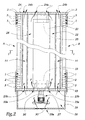
- FIGS. 1 to 4 The mechanics schematically represented in FIGS. 1 to 4 is formed by the mutual assembly of a multitude of housings 1 each of which contains several rotary actuators 2, the output shaft of which carries a pulley 3 for winding a yoke 4 connected to a rail 5 intended to control the wires of chain 6 of the loom.
- Each stringer is connected to the frame of the loom by an elastic return system 7.
- the different boxes 1 are assembled in rows perpendicular to the plane of Figure 1 and in parallel columns to this plane, so that they form two panels A and B arranged above the weaving area, that is to say above of the trade itself.
- Panels A and B form a V-shaped structure open upwards and carry plates 8 of guiding the arches 4 so as to avoid interference between these arches, while a drip board 9 is provided above beams 5.
- a frame 10 supports the panels A and B above of the trade in the above configuration.
- This frame includes a passageway 11 accessible by a staircase 12.
- the unit 20 includes, among others, a transformer, a rectifier-regulator block for power supply and for supplying one or more electronic cards actuator control 2.
- Unit 20 also includes a battery and a back-up battery, as well as a switching between the different possible sources of voltage.
- the unit 20 is connected by layers of conductive wires or conductive rods to the actuators 2 of each of the panels A and B. In practice, the conductive layers or rods are connected to electronic control cards 2 'associated with motors 2 in each of the housings 1, such a card being shown only in Figure 4.
- a cover 21 covers the unit 20 and the panels A and B.
- the aforementioned space forms a compartment 22 of reception and protection of the unit 20.
- the cover 21 is advantageously mounted in leaktight manner on the panels A and B, in order to close the upper opening 22 a of the compartment 22, which allows it to effectively protect the unit 20 from the wads of the ambient atmosphere.
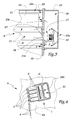
- Two plates 23 and 24 are provided at the ends of the compartment 22 and extend in planes overall perpendicular to panels A and B.
- Unit 20 is supported in compartment 22 thanks to two brackets 25 respectively fixed on the plates 23 and 24.
- the plate 23 also supports, thanks to a bracket 26, a ventilation unit 27 arranged inside a chamber 28 formed by a cover 29 mounted on the plate 23 and provided with an air inlet orifice 29 is equipped with a filter 30.
- the unit 27 to create an overpressure in the chamber 28, this pressure being distributed toward the inside of compartment 22 as an air flow shown by the arrows F in figures 2 and 3.
- This air flow has the effect of cooling the unit 20 which tends to heat up due to the current consumption.
- several ports 23a are provided in the plate 23 for the passage of cooling air, so that corresponding holes 24 a are provided on the plate 24 for the escape of cooling air.
- Channels 31 for cooling the actuators 2 are also provided in the panels A and B behind the actuators 2, these channels 31 being in communication with the chamber 28 by means of specific orifices 23 b aligned with exhaust orifices 24 b provided in plate 24.
- channels 31 can be provided with internal cooling fins boxes 1.
- the access to the unit 20 is done by removing the cover 21 from the opening 22 a which it seals at the upper edges of the panels A and B. An operator who stands on the passageway 11 can then easily proceed to mounting operations, control or maintenance of the constituent elements of the unit 20 by working in a satisfactory position in terms of ergonomics and with very good accessibility to these elements.
- the passageway 11 also provides access to the actuators 2 and / or to the arches 4 for their assembly and maintenance.
- the invention therefore makes it possible to increase the reliability of operator intervention and to save time when assembly and maintenance of a conforming loom to its principle. In fact, almost all of the cables and electrical connections can be made in the workshop and tested before shipping to the job site, then that the assembly obtained is compact, robust and economical.
Landscapes
- Engineering & Computer Science (AREA)
- Textile Engineering (AREA)
- Looms (AREA)
- Auxiliary Weaving Apparatuses, Weavers' Tools, And Shuttles (AREA)
- Knitting Machines (AREA)
Description
L'invention a trait aux machines utilisées pour la formation de la foule sur les métiers à tisser. Elle concerne, plus particulièrement, les mécaniques d'armure du type Jacquard. L'invention a également trait à un métier à tisser équipé d'une telle mécanique.The invention relates to machines used for crowd training on looms. It relates to, more particularly, the Jacquard type armor mechanics. The invention also relates to a loom equipped with such a mechanical.
Dans leur construction classique, les mécaniques Jacquard comprennent un dispositif d'actionnement de tête, placé au-dessus du métier, et un harnais reliant cette tête aux fils de chaíne tendus sur ce métier. Ce harnais comprend lui-même une série d'arcades directement et individuellement commandées par la tête dans un mouvement de déplacement vertical. Chacune des arcades est assemblée par un collet à une ou plusieurs lisses, chaque lisse portant un oeillet traversé par un fil de chaíne.In their classic construction, the Jacquard mechanics include a head actuator located above of the trade, and a harness connecting this head to the wires of chain stretched on this job. This harness itself includes a series of arcades directly and individually controlled by the head in a vertical movement. Each of arches is assembled by a collar with one or more beams, each stringer carrying an eyelet crossed by a chain wire.
Les dispositifs connus comprennent le plus souvent des cadres de griffes portant des griffes ou couteaux destinés à soulever ou non des crochets cinématiquement liés aux arcades. Le fait d'entraíner ces cadres de griffes avec un mouvement alternatif vertical nécessite l'utilisation d'une transmission mécanique élaborée, à partir de l'arbre central du métier, alors que la précision de la foule obtenue dépend des jeux mécaniques de cet ensemble cinématique. Les dispositifs mécaniques connus sont complexes et peu accessibles, ce qui perturbe leur assemblage et leur maintenance.Known devices most often include claw frames carrying claws or knives intended for whether or not to raise hooks kinematically linked to the arches. The fact of dragging these claw frames with a movement vertical reciprocating requires the use of a transmission mechanics developed, from the central tree of the trade, while the precision of the crowd obtained depends on the games mechanics of this kinematic assembly. The devices known mechanics are complex and inaccessible, which disrupts their assembly and maintenance.
Par ailleurs, FR 2 680 526 A divulgue un métier à tisser équipé
d'actionneurs utilisant des forces de Laplace. Ce métier est
d'un encombrement important.Furthermore,
L'invention vise à s'affranchir des limitations précitées en proposant une mécanique d'armure et un métier à tisser compacts, économiques et aisément accessibles, de telle sorte que leur mise en oeuvre est facilitée.The invention aims to overcome the above limitations by offering armor mechanics and a loom compact, economical and easily accessible, so that their implementation is facilitated.
Dans cet esprit, l'invention concerne une mécanique d'armure du type Jacquard pour la formation de la foule sur un métier à tisser, cette mécanique étant associée à un harnais comprenant des arcades, solidaires de lisses associées aux fils de chaíne du métier, les arcades étant commandées par des actionneurs électriques, caracterisée en ce que lesdits actionneurs sont ordonnés en rangées et/ou en colonnes formant deux panneaux disposés au-dessus du métier et en ce qu'une unité d'alimentation et de contrôle de ces actionneurs est logée dans un compartiment défini entre ces panneaux.In this spirit, the invention relates to a mechanical of Jacquard type armor for crowd training on a loom, this mechanism being associated with a harness comprising arches, integral with beams associated with the wires of the trade chain, the arches being controlled by electric actuators, characterized in that said actuators are ordered in rows and / or in columns forming two panels arranged above the profession and in that a power supply and control unit these actuators is housed in a compartment defined between these panels.
Grâce à l'invention, il est possible de faire cohabiter les panneaux formés de ces actionneurs et l'unité d'alimentation et de contrôle de ces actionneurs dans un ensemble compact et économique auquel on peut accéder aisément pour les opérations de montage et de maintenance du métier à tisser. Le compartiment ainsi formé protège efficacement l'unité d'alimentation et de contrôle de son environnement, notamment des chocs mécaniques et des poussières ou de la bourre environnante.Thanks to the invention, it is possible to make cohabit the panels formed by these actuators and the power unit and control of these actuators in a compact package economical and easily accessible for operations assembly and maintenance of the loom. The compartment thus formed effectively protects the power unit and control of its environment, especially shocks mechanical and dust or surrounding fluff.
Selon des aspects avantageux mais non obligatoires de l'invention, la mécanique incorpore une ou plusieurs des caractéristiques suivantes :
- Deux platines disposées aux extrémités des panneaux bordent le compartiment, l'une de ces platines supportant des moyens de contrôle en température de ce compartiment et/ou des actionneurs. Dans ce cas, les moyens de contrôle en température comprennent avantageusement une unité de ventilation apte à diriger vers l'unité d'alimentation et/ou de contrôle et/ou vers les actionneurs un courant d'air de refroidissement. Grâce à cet aspect de l'invention, l'unité de contrôle et les actionneurs peuvent être refroidis avec un même dispositif, ce qui est avantageux sur le plan de la fiabilité et du prix de revient de la mécanique de l'invention. On peut également prévoir que des panneaux forment ou portent des canaux de circulation d'air de ventilation des actionneurs, ces panneaux s'étendant globalement entre les platines à partir de l'unité de ventilation.
- La mécanique comprend une chambre de mise en surpression de l'air de refroidissement par l'unité de ventilation, cette chambre étant en communication, avec le compartiment et/ou des canaux formés ou portés par les panneaux, à travers des orifices ménagés dans la platine. Dans ce cas, la platine opposée est avantageusement pourvue d'orifices d'échappement de l'air de refroidissement en provenance du compartiment ou des canaux.
- Les panneaux sont inclinés l'un par rapport à l'autre, leur écartement allant croissant vers le haut, une ouverture d'accès au compartiment étant prévue au niveau des bords supérieurs de ces panneaux. Dans ce cas, un capot amovible de fermeture de cette ouverture est avantageusement prévu. On peut également intégrer à la structure du métier une coursive d'accès à cette ouverture.
- Les panneaux sont formés de boítiers de réception des actionneurs, ces boítiers étant assemblés les uns aux autres selon des rangées et/ou des colonnes.
- Two plates arranged at the ends of the panels border the compartment, one of these plates supporting means for controlling the temperature of this compartment and / or the actuators. In this case, the temperature control means advantageously comprise a ventilation unit capable of directing towards the supply and / or control unit and / or towards the actuators a stream of cooling air. Thanks to this aspect of the invention, the control unit and the actuators can be cooled with the same device, which is advantageous in terms of reliability and cost price of the mechanics of the invention. It is also possible to provide for panels to form or carry channels for circulating the ventilation air of the actuators, these panels extending generally between the plates from the ventilation unit.
- The mechanics comprises a chamber for boosting the cooling air by the ventilation unit, this chamber being in communication with the compartment and / or channels formed or carried by the panels, through orifices provided in the platinum. In this case, the opposite plate is advantageously provided with outlets for cooling air from the compartment or the channels.
- The panels are inclined relative to each other, their spacing increasing upward, an access opening to the compartment being provided at the upper edges of these panels. In this case, a removable cover for closing this opening is advantageously provided. One can also integrate into the structure of the trade a passageway to access this opening.
- The panels are formed from actuator receiving boxes, these boxes being assembled to each other in rows and / or columns.
L'invention concerne également un métier à tisser équipé d'une mécanique d'armure telle que précédemment décrite. Ce métier à tisser est plus simple à mettre en oeuvre et à entretenir que les métiers de l'art antérieur. Son rendement est sensiblement amélioré par rapport à la technique connue et il permet la commande fil à fil ou par groupes de plusieurs fils d'un harnais Jacquard.The invention also relates to a weaving loom equipped armor mechanics as previously described. This weaving loom is easier to implement and maintain that the trades of the prior art. Its performance is significantly improved compared to the known technique and it allows wire-to-wire or group control of several son of a Jacquard harness.
L'invention sera mieux comprise et d'autres avantages de celle-ci apparaítront plus clairement à la lumière de la description qui va suivre d'un mode de réalisation d'une mécanique d'armure et d'un métier à tisser conformes à son principe, donnée uniquement à titre d'exemple et faite en référence aux dessins annexés dans lesquels :
- la figure 1 est une coupe verticale schématique d'un métier à tisser conforme à l'invention ;
- la figure 2 est une coupe partielle à plus grande échelle selon la ligne II-II à la figure 1, on y a indiqué en I-I le plan de coupe de la figure 1 ;
- la figure 3 est une coupe partielle à plus grande échelle selon la ligne III-III à la figure 1 et
- la figure 4 est une vue de détail d'un boítier visible à la figure 1.
- Figure 1 is a schematic vertical section of a weaving loom according to the invention;
- Figure 2 is a partial section on a larger scale along the line II-II in Figure 1, there is indicated in II the section plane of Figure 1;
- FIG. 3 is a partial section on a larger scale along the line III-III in FIG. 1 and
- Figure 4 is a detail view of a housing visible in Figure 1.
La mécanique schématiquement représentée aux figures 1 à
4 est formée par l'assemblage mutuel d'une multitude de
boítiers 1 dont chacun renferme plusieurs actionneurs rotatifs
2 dont l'arbre de sortie porte une poulie 3 d'enroulement d'une
arcade 4 reliée à une lisse 5 destinée à commander les fils de
chaíne 6 du métier à tisser. Chaque lisse est reliée au bâti du
métier par un système de rappel élastique 7.The mechanics schematically represented in FIGS. 1 to
4 is formed by the mutual assembly of a multitude of
Les différents boítiers 1 sont assemblés en rangées
perpendiculaires au plan de la figure 1 et en colonnes parallèles
à ce plan, de telle sorte qu'ils forment deux panneaux A
et B disposés au-dessus de la zone de tissage, c'est-à-dire au-dessus
du métier lui même. Les panneaux A et B forment une
structure en V ouvert vers le haut et portent des plaques 8 de
guidage des arcades 4 de façon à éviter les interférences entre
ces arcades, alors qu'une planche d'empoutage 9 est prévue au-dessus
des lisses 5.The
Une ossature 10 permet de soutenir les panneaux A et B au-dessus
du métier dans la configuration précitée. Cette ossature
comprend une coursive 11 accessible par un escalier 12.A
Entre les panneaux A et B est défini un espace dont la
section dans le plan de la figure 1 est globalement triangulaire
et à l'intérieur duquel est logée une unité 20 d'alimentation
électrique et de contrôle des actionneurs 2.Between panels A and B is defined a space whose
section in the plane of Figure 1 is generally triangular
and inside which is housed a
L'unité 20 comprend, entre autres, un transformateur, un
bloc redresseur-régulateur pour l'alimentation de puissance et
pour l'alimentation d'une ou plusieurs cartes électroniques de
commande des actionneurs 2. L'unité 20 comprend également une
batterie et une batterie de secours, ainsi qu'un système de
commutation entre les différentes sources possibles de tension.
L'unité 20 est reliée par des nappes de fils conducteurs ou des
tiges conductrices aux actionneurs 2 de chacun des panneaux A
et B. En pratique, les nappes ou tiges conductrices sont
reliées à des cartes électroniques de commande 2' associées aux
moteurs 2 dans chacun des boítiers 1, une telle carte étant
représentée uniquement en figure 4.The
Un capot 21 couvre l'unité 20 et les panneaux A et B.A
Ainsi, l'espace précité forme un compartiment 22 de
réception et de protection de l'unité 20.Thus, the aforementioned space forms a
Le capot 21 est avantageusement monté de façon étanche sur
les panneaux A et B, pour obturer l'ouverture supérieure 22a du
compartiment 22, ce qui lui permet de protéger efficacement
l'unité 20 des bourres de l'atmosphère ambiante.The
Deux platines 23 et 24 sont prévues aux extrémités du
compartiment 22 et s'étendent dans des plans globalement
perpendiculaires aux panneaux A et B.Two
L'unité 20 est supportée dans le compartiment 22 grâce à
deux équerres 25 respectivement fixées sur les platines 23 et
24.
La platine 23 supporte également, grâce à une équerre 26,
une unité de ventilation 27 disposée à l'intérieur d'une
chambre 28 formée par un capot 29 monté sur la platine 23 et
pourvu d'un orifice d'entrée d'air 29a équipé d'un filtre 30.
L'unité 27 permet de créer une surpression dans la chambre 28,
cette surpression étant répartie vers l'intérieur du compartiment
22 sous forme d'un écoulement d'air représenté par les
flèches F aux figures 2 et 3. Cet écoulement d'air a pour effet
de refroidir l'unité 20 qui a tendance à s'échauffer du fait de
la consommation de courant. Pour ce faire, plusieurs orifices
23a sont prévus dans la platine 23 pour le passage de l'air de
refroidissement, alors que des orifices correspondants 24a sont
prévus sur la platine 24 pour l'échappement de l'air de
refroidissement.The
Des canaux 31 de refroidissement des actionneurs 2 sont
également prévus dans les panneaux A et B à l'arrière des
actionneurs 2, ces canaux 31 étant en communication avec la
chambre 28 grâce à des orifices spécifiques 23b alignés avec
des orifices d'échappement 24b prévus dans la platine 24.
Du fait de l'écoulement F de l'air en provenance de la
chambre 28, il est créé une surpression dans le compartiment 22
et dans les canaux 31, ce qui évite l'accumulation de bourre
dans ces volumes. Pour améliorer le transfert thermique, les
canaux 31 peuvent être pourvus d'ailettes internes de refroidissement
des boítiers 1.Due to the flow F of air from the
L'accès à l'unité 20 se fait en retirant le capot 21 de
l'ouverture 22a qu'il obture au niveau des bords supérieurs des
panneaux A et B. Un opérateur qui se tient sur la coursive 11
peut alors facilement procéder à des opérations de montage, de
contrôle ou de maintenance des éléments constitutifs de l'unité
20 en travaillant dans une position satisfaisante sur le plan
de l'ergonomie et avec une très bonne accessibilité à ces éléments.
La coursive 11 permet également d'accéder aux actionneurs
2 et/ou aux arcades 4 pour leur montage et leur maintenance.The access to the
L'invention permet donc d'augmenter la fiabilité des interventions d'un opérateur et de gagner du temps lors du montage et lors de la maintenance d'un métier à tisser conforme à son principe. En effet, la quasi totalité des câblages et des connections électriques peut être réalisée en atelier et testée avant expédition vers le site d'utilisation du métier, alors que l'ensemble obtenu est compact, robuste et économique.The invention therefore makes it possible to increase the reliability of operator intervention and to save time when assembly and maintenance of a conforming loom to its principle. In fact, almost all of the cables and electrical connections can be made in the workshop and tested before shipping to the job site, then that the assembly obtained is compact, robust and economical.
Claims (10)
- A dobby mechanism of Jacquard type for forming the shed on a loom, said mechanism being associated with a harness comprising harness cords (4) joined to healds (5) which are associated with the warp threads (6) of said loom, said harness cords being controlled by electric actuators (2), characterised in that said actuators are arranged in rows and/or in columns forming two panels (A, B) arranged above the loom and in that a unit (20) for supplying and controlling said actuators is housed in a compartment (22) defined between said panels.
- A mechanism according to Claim 1, characterised in that it comprises two plates (23, 24) arranged at the ends of said panels (A, B) and bordering said compartment (22), one of said plates supporting means (27-30) for controlling the temperature of said compartment and/or of said actuators (2).
- A mechanism according to Claim 2, characterised in that said temperature control means comprise a ventilation unit (27) able to direct a current of cooling air (F) towards said supply and/or control unit (20) and/or towards said actuators (2).
- A mechanism according to Claim 3, characterised in that said ventilation unit (27) is capable of creating an excess pressure in said compartment (22) compared with the ambient atmosphere.
- A mechanism according to one of Claims 3 or 4, characterised in that said panels form or bear channels (31) for circulating air for ventilating said actuators (2), said channels being supplied with cooling air via said ventilation unit (27) and extending overall between said plates (23, 24).
- A mechanism according to one of Claims 3 to 5, characterised in that it comprises a chamber (28) for pressurising the cooling air via said ventilation unit, said chamber communicating with said compartment (22) and/or channels (31) formed or borne by said panels (A, B) via orifices (23a, 23b) formed in said plate (23).
- A mechanism according to Claim 6, characterised in that the plate (24) opposing said plate (23) is provided with exhaust ports (24a, 24b) for the cooling air coming from said compartment (22) and/or said channels (31).
- A mechanism according to one of the preceding claims, characterised in that said panels are inclined relative to each other, the distance between them increasing upwards, an access opening (22a) to said compartment (22) being provided at the level of the upper edges of said panels.
- A mechanism according to one of the preceding claims, characterised in that said panels (A, B) are formed of box elements (1) for receiving said actuators (2), said box elements being assembled together in rows and/or columns.
- A loom, characterised in that it comprises a dobby mechanism (1-28) according to any one of the preceding claims.
Applications Claiming Priority (2)
| Application Number | Priority Date | Filing Date | Title |
|---|---|---|---|
| FR9907029A FR2794140B1 (en) | 1999-05-31 | 1999-05-31 | JACQUARD WEAPON MECHANICS AND WEAVING MACHINE EQUIPPED WITH SUCH MECHANICS |
| FR9907029 | 1999-05-31 |
Publications (2)
| Publication Number | Publication Date |
|---|---|
| EP1069218A1 EP1069218A1 (en) | 2001-01-17 |
| EP1069218B1 true EP1069218B1 (en) | 2002-07-24 |
Family
ID=9546344
Family Applications (1)
| Application Number | Title | Priority Date | Filing Date |
|---|---|---|---|
| EP00420105A Expired - Lifetime EP1069218B1 (en) | 1999-05-31 | 2000-05-23 | Jacquard shedding mechanism and weaving loom with such a mechanism |
Country Status (7)
| Country | Link |
|---|---|
| US (1) | US6216750B1 (en) |
| EP (1) | EP1069218B1 (en) |
| JP (1) | JP4447735B2 (en) |
| DE (1) | DE60000279T2 (en) |
| ES (1) | ES2179010T3 (en) |
| FR (1) | FR2794140B1 (en) |
| TW (1) | TW513496B (en) |
Cited By (1)
| Publication number | Priority date | Publication date | Assignee | Title |
|---|---|---|---|---|
| WO2016110764A1 (en) | 2015-01-07 | 2016-07-14 | Nv Michel Van De Wiele | Shed forming device with ventilation means |
Families Citing this family (13)
| Publication number | Priority date | Publication date | Assignee | Title |
|---|---|---|---|---|
| FR2826671B1 (en) * | 2001-06-29 | 2003-09-12 | Staubli Lyon | DEVICE FOR FORMING A CROWD ON A JACQUARD-TYPE WEAVING MATERIAL |
| FR2856705B1 (en) * | 2003-06-30 | 2005-08-05 | Staubli Sa Ets | ARMOR MECHANICS OF THE JACQUART TYPE, WEAVING EQUIPPED WITH SUCH A MECHANICAL AND METHODS OF ASSEMBLING AND DISASSEMBLING SUCH A MECHANICAL |
| JP2007507623A (en) * | 2003-10-02 | 2007-03-29 | アルバニー インターナショナル コーポレイション | Compact jacquard sorting card using piezoelectric elements |
| ITMI20030537U1 (en) * | 2003-11-19 | 2005-05-20 | Startes Jacquard S P A | TEXTILE FRAME EQUIPPED WITH A COOLING SYSTEM |
| EP1607501B1 (en) * | 2004-06-18 | 2007-07-25 | SCHÖNHERR Textilmaschinenbau GmbH | Method and device for shedding jacquard patterned pile warp yarns in a face to face weaving machine |
| WO2006119793A1 (en) * | 2005-05-12 | 2006-11-16 | Picanol N.V. | Actuator for a shed-forming device for a weaving machine |
| CN100349374C (en) * | 2005-11-21 | 2007-11-14 | 西北工业大学 | Motor operation control method of electron pattern machine |
| FR2990958B1 (en) * | 2012-05-24 | 2014-06-13 | Staubli Sa Ets | CROWN FORMING DEVICE AND WOVEN WEAVING EQUIPPED WITH SUCH A DEVICE |
| CN103034168A (en) * | 2012-12-11 | 2013-04-10 | 中国船舶重工集团公司第七〇五研究所 | Motion control structure of electronic pattern machine |
| CN106120074A (en) * | 2016-08-30 | 2016-11-16 | 海宁市舒雅达纺织有限公司 | A kind of jacquard faucet heat sink |
| JP7358335B2 (en) * | 2017-04-28 | 2023-10-10 | アンスパン, インコーポレイテッド | System and method for creating topographical woven fabrics |
| WO2018228694A1 (en) | 2017-06-15 | 2018-12-20 | Staubli Bayreuth Gmbh | Weaving machine, method for simultaneously weaving two pile fabrics on such a machine and pile fabric obtainable with such a method |
| CN108037746B (en) * | 2017-12-11 | 2019-09-03 | 江南大学 | A distributed high-speed multijacca control system and control method |
Family Cites Families (17)
| Publication number | Priority date | Publication date | Assignee | Title |
|---|---|---|---|---|
| US3733855A (en) * | 1970-12-02 | 1973-05-22 | Stibbe Machinery Ltd | Electronically controlled needle selection system for knitting machines |
| BE790077A (en) * | 1971-10-16 | 1973-04-13 | Sulzer Ag | ELECTROMECHANICAL DEVICE FOR TRAINING THE CROWD OF TRADE |
| SE8503794L (en) * | 1985-08-14 | 1987-02-15 | William E N Lauritsen | DEVICE FOR INDIVIDUAL CONTROL OF OSCILLATING MOVEMENTS OF PLATINES, SOLVES, NALAR OR SIMILAR TRADING ORGANIZATIONS IN A QUICK TEXTILE MACHINE |
| DE3713832C1 (en) * | 1987-04-24 | 1988-06-23 | Grosse Webereimaschinen Gmbh | Circuit board control device for open compartment jacquard machine |
| BE1000884A3 (en) * | 1987-08-26 | 1989-05-02 | De Vree & Co J | Device for forming of gaap to looms. |
| JPH01292135A (en) * | 1988-05-13 | 1989-11-24 | Murata Mach Ltd | Dobby machine |
| GB8902849D0 (en) * | 1989-02-09 | 1989-03-30 | Bonas Machine Co | Heald rod retention system for use with an electronic jacquard system |
| FR2662710B1 (en) * | 1990-05-31 | 1992-08-28 | Staubli Sa Ets | ELECTRO-MAGNETIC UNIT FOR THE CONTROL OF RATIERES AND OTHER WEAVING MECHANICS. |
| JP2922689B2 (en) * | 1991-05-28 | 1999-07-26 | 津田駒工業株式会社 | Loom abnormality detection method |
| FR2680526A1 (en) * | 1991-08-19 | 1993-02-26 | Galineau Edouard | Weaving loom |
| JPH0571036A (en) * | 1991-09-10 | 1993-03-23 | Nippon Filcon Co Ltd | Device for shed using heald having one supported end and method for weaving and joining using the same device |
| US5462097A (en) | 1992-07-03 | 1995-10-31 | Textilma Ag | Piezoelectric devices for yarn control apparatus in a textile machine |
| FR2772796B1 (en) | 1997-12-24 | 2000-01-28 | Staubli Sa Ets | METHOD FOR MOUNTING A FUNICULAR ELEMENT, A CROWD FORMING DEVICE AND A WEAVING MATERIAL |
| FR2772791B1 (en) | 1997-12-24 | 2000-01-28 | Staubli Sa Ets | ELECTRIC ROTARY ACTUATOR FOR CROWD FORMATION ON WEAVING MATERIAL, WEAVING MECHANICS AND WEAVING MATERIAL |
| FR2772794B1 (en) | 1997-12-24 | 2000-01-28 | Staubli Sa Ets | JACQUARD WEAPON MECHANICS AND WEAVING MACHINE EQUIPPED WITH SUCH MECHANICS |
| FR2772793B1 (en) | 1997-12-24 | 2000-01-28 | Staubli Sa Ets | LOCKING DEVICE OF AN ELECTRIC ROTARY ACTUATOR FOR FORMING CROWD ON WEAVING MATERIAL, WEAVING MECHANICS AND WEAVING MATERIAL |
| FR2772792B1 (en) | 1997-12-24 | 2000-01-28 | Staubli Sa Ets | ELECTRIC ACTUATOR POSITIONING BOX FOR CROWD FORMATION AND WEAVING |
-
1999
- 1999-05-31 FR FR9907029A patent/FR2794140B1/en not_active Expired - Fee Related
-
2000
- 2000-05-15 TW TW089109236A patent/TW513496B/en not_active IP Right Cessation
- 2000-05-22 US US09/575,752 patent/US6216750B1/en not_active Expired - Fee Related
- 2000-05-23 ES ES00420105T patent/ES2179010T3/en not_active Expired - Lifetime
- 2000-05-23 EP EP00420105A patent/EP1069218B1/en not_active Expired - Lifetime
- 2000-05-23 DE DE60000279T patent/DE60000279T2/en not_active Expired - Lifetime
- 2000-05-24 JP JP2000153256A patent/JP4447735B2/en not_active Expired - Fee Related
Cited By (1)
| Publication number | Priority date | Publication date | Assignee | Title |
|---|---|---|---|---|
| WO2016110764A1 (en) | 2015-01-07 | 2016-07-14 | Nv Michel Van De Wiele | Shed forming device with ventilation means |
Also Published As
| Publication number | Publication date |
|---|---|
| DE60000279D1 (en) | 2002-08-29 |
| US6216750B1 (en) | 2001-04-17 |
| EP1069218A1 (en) | 2001-01-17 |
| JP4447735B2 (en) | 2010-04-07 |
| DE60000279T2 (en) | 2003-04-03 |
| TW513496B (en) | 2002-12-11 |
| FR2794140B1 (en) | 2001-07-13 |
| FR2794140A1 (en) | 2000-12-01 |
| ES2179010T3 (en) | 2003-01-16 |
| JP2000345443A (en) | 2000-12-12 |
Similar Documents
| Publication | Publication Date | Title |
|---|---|---|
| EP1069218B1 (en) | Jacquard shedding mechanism and weaving loom with such a mechanism | |
| EP1844646A3 (en) | Hedge shears | |
| EP3767825B1 (en) | Inspection system for concentrating photovoltaic apparatus and inspection method for light receiving part | |
| EP0382605B1 (en) | Device for depositing a piece of wiring in a plane | |
| EP0926282B1 (en) | Jacquard shedding mechanism and weaving loom with such a mechanism | |
| EP1953276B1 (en) | Shed forming device including electric motor blocks and loom equipped with such a device | |
| JP4173441B2 (en) | Jacquard type loom opening device | |
| US5563774A (en) | Lawnmower headlight system | |
| FR2802219A1 (en) | Device moving laths in Jacquard loom has single input shaft driving two superposed parallel drive shafts fitted with rocker arms connected to laths | |
| EP1270779B1 (en) | Guiding device, Jacquard harness and shedding machanism with such a device and guiding method for the harness cords of a Jacquard loom | |
| EP0926280B1 (en) | Positioning housing for the electrical actuators of a shedding mechanism and weaving loom | |
| FR2650311A1 (en) | Machine for continuously dyeing textile yarns | |
| EP0570318B1 (en) | Process for weaving thick reinforcement with several undelaminable layers for composite material and loom for its manufacture | |
| DE102010006465A1 (en) | LED-structural unit for lighting application, has LED-carrier formed as flat panel, arranged on tray and locked by sealing compound, lens enclosing bottom of housing so as to form tray, and frame held by laces | |
| BE898160A (en) | Heald control system for a moving loom with moving ripples. | |
| EP3150754B1 (en) | Control system for a jacquard mechanism, jacquard mechanism and weaving machine equipped with such a system | |
| CA2348583C (en) | Arrangement for noise reduction, air-conditioning and accident prevention for a jacquard weaving machine and jacquard weaving machine with an arrangement | |
| FR2485573A1 (en) | DEVICE FOR INSERTING FRAME WIRE FOR WORKINGS WITHOUT SHUTTLE | |
| JP2019202709A (en) | Battery module | |
| EP0556165A1 (en) | Single heald selection and control device | |
| EP1069219B1 (en) | Selvedge shedding device and weaving loom with such a device | |
| JP3888726B2 (en) | Mouth forming device for textile machinery | |
| KR100860572B1 (en) | Observation | |
| EP1014068A1 (en) | Machine for testing at least two different types of pieces | |
| BE905884Q (en) | DEVICE FOR CONTROLLING WEAVING HANDLES. |
Legal Events
| Date | Code | Title | Description |
|---|---|---|---|
| PUAI | Public reference made under article 153(3) epc to a published international application that has entered the european phase |
Free format text: ORIGINAL CODE: 0009012 |
|
| AK | Designated contracting states |
Kind code of ref document: A1 Designated state(s): BE DE ES FR GB IT |
|
| AX | Request for extension of the european patent |
Free format text: AL;LT;LV;MK;RO;SI |
|
| 17P | Request for examination filed |
Effective date: 20010322 |
|
| AKX | Designation fees paid |
Free format text: BE DE ES FR GB IT |
|
| GRAG | Despatch of communication of intention to grant |
Free format text: ORIGINAL CODE: EPIDOS AGRA |
|
| 17Q | First examination report despatched |
Effective date: 20011108 |
|
| GRAG | Despatch of communication of intention to grant |
Free format text: ORIGINAL CODE: EPIDOS AGRA |
|
| GRAH | Despatch of communication of intention to grant a patent |
Free format text: ORIGINAL CODE: EPIDOS IGRA |
|
| GRAH | Despatch of communication of intention to grant a patent |
Free format text: ORIGINAL CODE: EPIDOS IGRA |
|
| GRAA | (expected) grant |
Free format text: ORIGINAL CODE: 0009210 |
|
| AK | Designated contracting states |
Kind code of ref document: B1 Designated state(s): BE DE ES FR GB IT |
|
| REG | Reference to a national code |
Ref country code: GB Ref legal event code: FG4D Free format text: NOT ENGLISH |
|
| GBT | Gb: translation of ep patent filed (gb section 77(6)(a)/1977) |
Effective date: 20020724 |
|
| REF | Corresponds to: |
Ref document number: 60000279 Country of ref document: DE Date of ref document: 20020829 |
|
| REG | Reference to a national code |
Ref country code: ES Ref legal event code: FG2A Ref document number: 2179010 Country of ref document: ES Kind code of ref document: T3 |
|
| PLBE | No opposition filed within time limit |
Free format text: ORIGINAL CODE: 0009261 |
|
| STAA | Information on the status of an ep patent application or granted ep patent |
Free format text: STATUS: NO OPPOSITION FILED WITHIN TIME LIMIT |
|
| 26N | No opposition filed |
Effective date: 20030425 |
|
| PGFP | Annual fee paid to national office [announced via postgrant information from national office to epo] |
Ref country code: ES Payment date: 20080522 Year of fee payment: 9 |
|
| PGFP | Annual fee paid to national office [announced via postgrant information from national office to epo] |
Ref country code: GB Payment date: 20080506 Year of fee payment: 9 |
|
| GBPC | Gb: european patent ceased through non-payment of renewal fee |
Effective date: 20090523 |
|
| PG25 | Lapsed in a contracting state [announced via postgrant information from national office to epo] |
Ref country code: GB Free format text: LAPSE BECAUSE OF NON-PAYMENT OF DUE FEES Effective date: 20090523 |
|
| REG | Reference to a national code |
Ref country code: ES Ref legal event code: FD2A Effective date: 20090525 |
|
| PG25 | Lapsed in a contracting state [announced via postgrant information from national office to epo] |
Ref country code: ES Free format text: LAPSE BECAUSE OF NON-PAYMENT OF DUE FEES Effective date: 20090525 |
|
| REG | Reference to a national code |
Ref country code: FR Ref legal event code: PLFP Year of fee payment: 17 |
|
| PGFP | Annual fee paid to national office [announced via postgrant information from national office to epo] |
Ref country code: DE Payment date: 20160527 Year of fee payment: 17 |
|
| PGFP | Annual fee paid to national office [announced via postgrant information from national office to epo] |
Ref country code: FR Payment date: 20160530 Year of fee payment: 17 Ref country code: IT Payment date: 20160520 Year of fee payment: 17 Ref country code: BE Payment date: 20160527 Year of fee payment: 17 |
|
| REG | Reference to a national code |
Ref country code: DE Ref legal event code: R119 Ref document number: 60000279 Country of ref document: DE |
|
| REG | Reference to a national code |
Ref country code: FR Ref legal event code: ST Effective date: 20180131 |
|
| REG | Reference to a national code |
Ref country code: BE Ref legal event code: MM Effective date: 20170531 |
|
| PG25 | Lapsed in a contracting state [announced via postgrant information from national office to epo] |
Ref country code: DE Free format text: LAPSE BECAUSE OF NON-PAYMENT OF DUE FEES Effective date: 20171201 |
|
| PG25 | Lapsed in a contracting state [announced via postgrant information from national office to epo] |
Ref country code: FR Free format text: LAPSE BECAUSE OF NON-PAYMENT OF DUE FEES Effective date: 20170531 Ref country code: IT Free format text: LAPSE BECAUSE OF NON-PAYMENT OF DUE FEES Effective date: 20170523 |
|
| PG25 | Lapsed in a contracting state [announced via postgrant information from national office to epo] |
Ref country code: BE Free format text: LAPSE BECAUSE OF NON-PAYMENT OF DUE FEES Effective date: 20170531 |