EP1069015A2 - Druckmittelbetätigte Fahrzeugbremsanlage - Google Patents
Druckmittelbetätigte Fahrzeugbremsanlage Download PDFInfo
- Publication number
- EP1069015A2 EP1069015A2 EP00111081A EP00111081A EP1069015A2 EP 1069015 A2 EP1069015 A2 EP 1069015A2 EP 00111081 A EP00111081 A EP 00111081A EP 00111081 A EP00111081 A EP 00111081A EP 1069015 A2 EP1069015 A2 EP 1069015A2
- Authority
- EP
- European Patent Office
- Prior art keywords
- pressure
- valve
- brake
- control
- input
- Prior art date
- Legal status (The legal status is an assumption and is not a legal conclusion. Google has not performed a legal analysis and makes no representation as to the accuracy of the status listed.)
- Granted
Links
Images


Classifications
-
- B—PERFORMING OPERATIONS; TRANSPORTING
- B60—VEHICLES IN GENERAL
- B60T—VEHICLE BRAKE CONTROL SYSTEMS OR PARTS THEREOF; BRAKE CONTROL SYSTEMS OR PARTS THEREOF, IN GENERAL; ARRANGEMENT OF BRAKING ELEMENTS ON VEHICLES IN GENERAL; PORTABLE DEVICES FOR PREVENTING UNWANTED MOVEMENT OF VEHICLES; VEHICLE MODIFICATIONS TO FACILITATE COOLING OF BRAKES
- B60T8/00—Arrangements for adjusting wheel-braking force to meet varying vehicular or ground-surface conditions, e.g. limiting or varying distribution of braking force
- B60T8/32—Arrangements for adjusting wheel-braking force to meet varying vehicular or ground-surface conditions, e.g. limiting or varying distribution of braking force responsive to a speed condition, e.g. acceleration or deceleration
- B60T8/88—Arrangements for adjusting wheel-braking force to meet varying vehicular or ground-surface conditions, e.g. limiting or varying distribution of braking force responsive to a speed condition, e.g. acceleration or deceleration with failure responsive means, i.e. means for detecting and indicating faulty operation of the speed responsive control means
- B60T8/92—Arrangements for adjusting wheel-braking force to meet varying vehicular or ground-surface conditions, e.g. limiting or varying distribution of braking force responsive to a speed condition, e.g. acceleration or deceleration with failure responsive means, i.e. means for detecting and indicating faulty operation of the speed responsive control means automatically taking corrective action
- B60T8/94—Arrangements for adjusting wheel-braking force to meet varying vehicular or ground-surface conditions, e.g. limiting or varying distribution of braking force responsive to a speed condition, e.g. acceleration or deceleration with failure responsive means, i.e. means for detecting and indicating faulty operation of the speed responsive control means automatically taking corrective action on a fluid pressure regulator
-
- B—PERFORMING OPERATIONS; TRANSPORTING
- B60—VEHICLES IN GENERAL
- B60T—VEHICLE BRAKE CONTROL SYSTEMS OR PARTS THEREOF; BRAKE CONTROL SYSTEMS OR PARTS THEREOF, IN GENERAL; ARRANGEMENT OF BRAKING ELEMENTS ON VEHICLES IN GENERAL; PORTABLE DEVICES FOR PREVENTING UNWANTED MOVEMENT OF VEHICLES; VEHICLE MODIFICATIONS TO FACILITATE COOLING OF BRAKES
- B60T13/00—Transmitting braking action from initiating means to ultimate brake actuator with power assistance or drive; Brake systems incorporating such transmitting means, e.g. air-pressure brake systems
- B60T13/10—Transmitting braking action from initiating means to ultimate brake actuator with power assistance or drive; Brake systems incorporating such transmitting means, e.g. air-pressure brake systems with fluid assistance, drive, or release
- B60T13/66—Electrical control in fluid-pressure brake systems
- B60T13/68—Electrical control in fluid-pressure brake systems by electrically-controlled valves
- B60T13/683—Electrical control in fluid-pressure brake systems by electrically-controlled valves in pneumatic systems or parts thereof
-
- B—PERFORMING OPERATIONS; TRANSPORTING
- B60—VEHICLES IN GENERAL
- B60T—VEHICLE BRAKE CONTROL SYSTEMS OR PARTS THEREOF; BRAKE CONTROL SYSTEMS OR PARTS THEREOF, IN GENERAL; ARRANGEMENT OF BRAKING ELEMENTS ON VEHICLES IN GENERAL; PORTABLE DEVICES FOR PREVENTING UNWANTED MOVEMENT OF VEHICLES; VEHICLE MODIFICATIONS TO FACILITATE COOLING OF BRAKES
- B60T15/00—Construction arrangement, or operation of valves incorporated in power brake systems and not covered by groups B60T11/00 or B60T13/00
- B60T15/02—Application and release valves
- B60T15/04—Driver's valves
- B60T15/14—Driver's valves influencing electric control means
-
- B—PERFORMING OPERATIONS; TRANSPORTING
- B60—VEHICLES IN GENERAL
- B60T—VEHICLE BRAKE CONTROL SYSTEMS OR PARTS THEREOF; BRAKE CONTROL SYSTEMS OR PARTS THEREOF, IN GENERAL; ARRANGEMENT OF BRAKING ELEMENTS ON VEHICLES IN GENERAL; PORTABLE DEVICES FOR PREVENTING UNWANTED MOVEMENT OF VEHICLES; VEHICLE MODIFICATIONS TO FACILITATE COOLING OF BRAKES
- B60T8/00—Arrangements for adjusting wheel-braking force to meet varying vehicular or ground-surface conditions, e.g. limiting or varying distribution of braking force
- B60T8/32—Arrangements for adjusting wheel-braking force to meet varying vehicular or ground-surface conditions, e.g. limiting or varying distribution of braking force responsive to a speed condition, e.g. acceleration or deceleration
- B60T8/321—Arrangements for adjusting wheel-braking force to meet varying vehicular or ground-surface conditions, e.g. limiting or varying distribution of braking force responsive to a speed condition, e.g. acceleration or deceleration deceleration
- B60T8/3255—Systems in which the braking action is dependent on brake pedal data
- B60T8/327—Pneumatic systems
-
- B—PERFORMING OPERATIONS; TRANSPORTING
- B60—VEHICLES IN GENERAL
- B60T—VEHICLE BRAKE CONTROL SYSTEMS OR PARTS THEREOF; BRAKE CONTROL SYSTEMS OR PARTS THEREOF, IN GENERAL; ARRANGEMENT OF BRAKING ELEMENTS ON VEHICLES IN GENERAL; PORTABLE DEVICES FOR PREVENTING UNWANTED MOVEMENT OF VEHICLES; VEHICLE MODIFICATIONS TO FACILITATE COOLING OF BRAKES
- B60T8/00—Arrangements for adjusting wheel-braking force to meet varying vehicular or ground-surface conditions, e.g. limiting or varying distribution of braking force
- B60T8/32—Arrangements for adjusting wheel-braking force to meet varying vehicular or ground-surface conditions, e.g. limiting or varying distribution of braking force responsive to a speed condition, e.g. acceleration or deceleration
- B60T8/34—Arrangements for adjusting wheel-braking force to meet varying vehicular or ground-surface conditions, e.g. limiting or varying distribution of braking force responsive to a speed condition, e.g. acceleration or deceleration having a fluid pressure regulator responsive to a speed condition
- B60T8/343—Systems characterised by their lay-out
-
- B—PERFORMING OPERATIONS; TRANSPORTING
- B60—VEHICLES IN GENERAL
- B60T—VEHICLE BRAKE CONTROL SYSTEMS OR PARTS THEREOF; BRAKE CONTROL SYSTEMS OR PARTS THEREOF, IN GENERAL; ARRANGEMENT OF BRAKING ELEMENTS ON VEHICLES IN GENERAL; PORTABLE DEVICES FOR PREVENTING UNWANTED MOVEMENT OF VEHICLES; VEHICLE MODIFICATIONS TO FACILITATE COOLING OF BRAKES
- B60T8/00—Arrangements for adjusting wheel-braking force to meet varying vehicular or ground-surface conditions, e.g. limiting or varying distribution of braking force
- B60T8/32—Arrangements for adjusting wheel-braking force to meet varying vehicular or ground-surface conditions, e.g. limiting or varying distribution of braking force responsive to a speed condition, e.g. acceleration or deceleration
- B60T8/34—Arrangements for adjusting wheel-braking force to meet varying vehicular or ground-surface conditions, e.g. limiting or varying distribution of braking force responsive to a speed condition, e.g. acceleration or deceleration having a fluid pressure regulator responsive to a speed condition
- B60T8/36—Arrangements for adjusting wheel-braking force to meet varying vehicular or ground-surface conditions, e.g. limiting or varying distribution of braking force responsive to a speed condition, e.g. acceleration or deceleration having a fluid pressure regulator responsive to a speed condition including a pilot valve responding to an electromagnetic force
- B60T8/3605—Arrangements for adjusting wheel-braking force to meet varying vehicular or ground-surface conditions, e.g. limiting or varying distribution of braking force responsive to a speed condition, e.g. acceleration or deceleration having a fluid pressure regulator responsive to a speed condition including a pilot valve responding to an electromagnetic force wherein the pilot valve is mounted in a circuit controlling the working fluid system
Definitions
- the invention relates to a vehicle brake system according to the Genus of the main claim.
- Such a vehicle brake system is known from EP 0 726 190 known and intended for a commercial vehicle.
- a first serves Brake circuit as a pneumatically operated rear axle brake circuit for the two wheels on the rear axle and a second brake circuit as pneumatic Actuable front axle brake circuit for the front axle. In the event of failure one brake circuit should be the other brake circuit of the commercial vehicle delay enough.
- the brake cylinders of the rear axle brake circuit are each designed as a combination brake cylinder, which has a first control valve device as a function of a rear axle brake circuit assigned control signal of a multi-circuit brake value transmitter can be connected to a compressed air reservoir for the rear axle brake circuit.
- the brake cylinders of the front axle brake circuit have a second one Control valve device as a function of a front axle brake circuit assigned control signal of the multi-circuit brake value transmitter can be connected to a compressed air reservoir for the front axle brake circuit.
- the second control valve device has one with the compressed air reservoir for the front axle brake circuit connected first pressure input and one with a control output of the multi-circuit brake value transmitter or Service brake valve connected second pressure input through which a front axle control pressure derived from the service brake valve is controlled.
- the second control valve device also has the Brake cylinders on the front axle connected pressure outputs.
- the known vehicle brake system one between the second control valve device and a brake cylinder of the right front wheel arranged changeover valve device is provided, the pressure medium in the event of failure of the front axle brake circuit the compressed air reservoir independent of the front axle brake circuit Brake cylinder switches to there as a replacement for the failed one Serve front axle brake pressure.
- Unsatisfactory at this level Technology is that this asymmetrical circuit construction different flow resistances for the axle sides of the front axle result that there is too dynamic with intact braking lead to unequal brake pressure profiles.
- the pressure-operated vehicle brake system according to the invention has the advantage that due to intact braking the arrangement of the switching valve device according to the invention between the inflow side of the second control valve device and the Downstream side of the two pressure medium sources symmetrical flow resistances for both axle sides of the front axle, while at A failure of the front axle brake circuit by the auxiliary braking effect Switch to a pressure medium source that is independent of the front axle brake circuit both brake cylinders of the front axle can be fed.
- Vehicle braking system is an electronically controlled braking system for commercial vehicles with priority electro-pneumatic brake circuits and with subordinate pneumatic restraint circuits as an underlying safety level.
- the front axle brakes are in the electronically controlled brake system 1 by a brake cylinder 2 of the left front wheel and represents a brake cylinder 4 of the right front wheel, which of a pressure control module 6 are controlled.
- the pressure control module 6 of the Front axle is with its first pressure input 7 via a changeover valve device 100 connectable to compressed air reservoirs 12 or 14 while its second pressure inlet 9 to the control side of a front axle channel 15 'of a service brake valve 15 is connected.
- the front axle channel 15 'of the service brake valve 15 is on the input side by means of the switching valve device 100 via a supply pressure line 16 can be connected to the compressed air reservoir 14 of the front axle, to depending on the force with which the driver depresses the control pedal actuated, proportional control pressure signals into a control pressure line 17 the front axle.
- a proportional electrical control signal generated and on via an electrical line 18 a central electronic control unit 20 directed, which by means of a not shown - electrical control line, the pressure control module 6 Controls the front axle.
- a modulated control pressure is generated and via pneumatic brake pressure lines 23 controlled in the brake cylinders 2, 4.
- the compressed air reservoir 14 for the front axle, the electrical part 15 '' 'of the service brake valve 15, the central electronic control unit 20, the associated electrical Control lines, the pressure control module 6, the brake pressure lines 23 and the brake cylinders 2, 4 together form an electropneumatic Front axle brake circuit.
- the circuit logic of the pressure control module 6 deals with the electrical Control signals of the electropneumatic front axle brake circuit primarily over the control pressure signals controlled via the control pressure line 17 of a pneumatic front axle brake circuit, which as a restraint brake circuit performs a redundant control function if the electro-pneumatic front axle brake circuit is faulty.
- the electropneumatic Front axle brake circuit partially overlaps the pneumatic front axle brake circuit, which the compressed air reservoir 14 for the front axle, the front axle duct 15 'of the service brake valve 15, the control pressure line 17, the pressure control module 6, the brake pressure lines 23 and the two brake cylinders 2, 4 comprises.
- the pressure control module 6 of the front axle enables in addition to the Regulation of the brake pressure through integrated ABS (anti-lock braking system) - Functions an individual adjustment of the brake pressure to the turning behavior the braked front wheels, which from wheel-related speed sensors measured and by means of electrical lines to the pressure control module 6 is directed.
- ABS anti-lock braking system
- An electro-pneumatic rear axle brake circuit is analogous and a subordinate pneumatic rear axle brake circuit built, with a separate one for the rear axle Compressed air reservoir 27 is provided, which is through a supply pressure line 30 on the one hand with the input of a rear axle duct 15 '' of the service brake valve 15 and on the other hand with a pressure control module 31 Rear axle is connected.
- the service brake valve 15 controls on the one hand a control pressure line 32 control pressure signals into the pressure control module 31 of the rear axle via pneumatic brake pressure lines 33 with combination brake cylinders 34 of the right and left rear wheel in Connection is established.
- the service brake valve 15 via the electrical line 18 to the central electronic control unit 20 driven electrical signals by means of a - not shown - Electrical control line in the pressure control module 31 of the rear axle controlled.
- the switching valve device 100 is equipped with a first pressure input 50 'via a pneumatic connecting line 16' connected to the compressed air reservoir 14 assigned to the front axle, while a second pressure inlet 50 ′′ via the supply pressure line 36 with the compressed air reservoir 12 serving as an auxiliary store pneumatically connected is.
- a pressure outlet 51 of the switching valve device 100 is via the supply pressure line 16 on the one hand to the front axle duct 15 ' of the service brake valve 15 connected and on the other hand with the Pressure input 7 of the pressure control module 6 connected.
- Fig. 2 shows a first embodiment of the invention Umschaltventileinnchtung 100, which a shuttle valve 101 with a first pressure input 50 ', a second pressure input 50' 'and one Pressure outlet 51 includes, the first pressure inlet 50 'by a predetermined Pressure measure ⁇ p is preferred to the second pressure input is, so that the one with the higher supply pressure Pressure input 50 ', 50' 'is switched through to pressure output 51.
- ⁇ p a predetermined Pressure measure
- the first pressure input 50 'over the connecting line 16 'with the compressed air reservoir 14 for the front axle and the second pressure inlet 50 ′′ via line 36 with the Auxiliary storage 12 is connected remains in normal printing conditions Front axle brake circuit, i.e. if in the compressed air reservoir 14 of the front axle or no pressure losses occur in line 16, the first Pressure input 50 'connected to the pressure output 51.
- the supply pressure comes from the compressed air reservoir 14 via the line 16 on the one hand to the front axle duct 15 'of the service brake valve 15 and on the other hand to the pressure input 7 of the pressure control module 6.
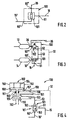
- Fig. 3 shows a second embodiment of the changeover valve device 100 according to the invention, which comprises a shuttle valve 101 and a spring-loaded pressure limiter 102, the first pressure inlet 50 'of the shuttle valve 101 via the supply pressure line 16' with the compressed air reservoir 14 assigned to the front axle and one as a second pressure inlet 50 ′′ of the changeover valve device 100 acting pressure input of the pressure limiter 102 is connected via line 36 to the auxiliary accumulator 12. On the pressure outlet side, the pressure limiter 102 is connected via line 53 to the second pressure inlet of the shuttle valve 101.
- the pressure limiter 102 has a control connection 52 which is connected to a branch of the control pressure line 32.
- the pressure limiter 102 opens the supply pressure line 36 only when the service brake valve 15 is actuated, pressure medium coming from the auxiliary reservoir 12 via the line 53 to the second pressure input of the shuttle valve 101.
- the pressure limiter 102 switches from its blocking rest position at a predetermined pressure level as a function of the control pressure p HA controlled by the service brake valve 15.
- this embodiment is switched by the brake pressure, which is controlled from the service brake valve 15 to the rear axle. In this case, the tightness and circular separation of the compressed air accumulators 12, 14 can be checked by the intermittent action on both sides of the shuttle valve 101.
- the pressure limiter 102 has a valve housing 150, within which a valve piston 151 is arranged to be longitudinally movable in order to actuate an inlet and an outlet valve 152, 153.
- a valve spring 154 By means of a valve spring 154, the valve piston 151 is biased with its end-side piston pin 155 against a closing body 156 mounted on the inlet valve 152.
- a control chamber 157 is delimited by an active surface of the valve piston 151 and an intermediate floor 158 of the valve housing 150 and has an inlet 159 for the control connection 52 of the changeover valve device 100.
- Seals 160 between the valve piston 151 and the valve housing 150 serve to seal the control chamber 157 from the inlet and outlet valve 152, 153. Furthermore, an intermediate ventilation duct 161 is arranged between the inlet 159 to the control chamber 157 and the outlet valve 153. If there is not sufficient control pressure p HA at the inlet 159 and thus in the control chamber 157, the valve piston 151 acts on the closing body 156 under the action of the valve spring 154, the closing body 156 sealing the inlet valve 152, so that a through the inlet and Exhaust valve 152, 153 defined flow channel is closed.
- valve piston 151 experiences a resultant upward force, the piston pin 155 and the adjacent closing body 156 lifting off the inlet valve 152 and thus releasing the flow channel from the inlet valve 152 to the outlet valve 153.
- the inlet valve 152 corresponds to the pressure input 50 ′′
- pressure medium flows from the auxiliary accumulator 12 to the outlet valve 153 via this flow channel, the pressure present at the outlet valve 153 being a function of the control pressure p HA supplied to the control chamber 157 and thus being stepped.
- the outlet valve 153 of the pressure limiter 102 is connected to the second pressure input of the shuttle valve 101, the shuttle valve 101 comprising a valve housing 162 with a valve body 163 which is then accommodated and which is provided for alternately actuating the first and second pressure inputs of the shuttle valve 101 .
- the first pressure inlet 50 'of the shuttle valve 101 is connected to the front axle compressed air reservoir 14 via the supply pressure line 16'.
- valve body 163 acts on a valve seat assigned to the pressure input located opposite. As a result, this pressure input is shut off and a flow channel is formed which extends from the pressure input to which the higher pressure is applied to the pressure output 51.
- Changeover valve device 100 which is a spring-loaded 3/2-way valve 103 includes.
- a first inlet 50 'of the 3/2 way valve 103 the supply pressure line 16 'of the front axle compressed air reservoir 14 is connected, while a second input 50 '' of the valve 103 with the for Auxiliary storage 12 leading supply pressure line 36 is connected.
- the 3/2-way valve 103 with a first control input 52 on the pneumatic control pressure signals of the rear axle brake circuit leading connecting line 32 is connected and stands with a second control input 170 via a branched off from the supply pressure line 16 ' Line in connection.
- the 3/2-way valve blocks 103 the supply pressure line 36 and connects at the same time the supply pressure line 16 with its outlet 51, while in its second position shut off the supply pressure line 16 and the supply pressure line 36 is connected to the output 51.
- This output is 51 via line 16 to the first pressure inlet 7 of the pressure control module 6 connected.
- the 3/2-way valve 103 is thus activated via the control pressure line 32 of the rear axle restraint brake circuit.
- the 3/2-way valve 103 When the front axle brake circuit is intact, the 3/2-way valve 103 remains in its rest position, so that the pressure from the compressed air reservoir 14 is present at the first pressure input 7 of the pressure control module 6, while the control pressure p VA supplied via the control pressure line 17 is present at the second pressure input 9 reached. If the pressure in the pneumatic front axle brake circuit drops, both the pressure at the inlet 50 'of the 3/2-way valve 103 and at its control inlet 170 drops, so that the 3/2-way valve 103 during braking as a result of the pressure p HA in the control pressure line 32 switches to its second position, the stepped auxiliary pressure from the auxiliary store 12 now being present at its output 51 and thus at the first pressure input 7 of the pressure control module 6.
- FIG. 6 illustrates a highly schematic implementation of the third embodiment of the changeover valve device 100 according to the invention.
- the 3/2-way valve 103 has a valve housing 180 within which a valve piston 181 is arranged to be longitudinally movable, alternately one from a first or a second Inlet valve 50 ', 50''to switch to an outlet valve 51 extending flow channel.
- a first control chamber 182 is delimited by a first active surface 183 of the valve piston 181 and an abutment wall 184 of the valve housing 180, the valve piston 181 being pretensioned by means of a valve spring 185 arranged in the control chamber 182 and the control chamber 182 having an inlet channel 195 opening to the pressure input 50 ' .
- a second control chamber 186 is delimited by a second active surface 187 of the valve piston 181 and an intermediate wall 188 of the valve housing 180 and has a laterally arranged control input 52 for the control pressure p HA .
- the valve piston 181 protrudes into a working chamber 189, which contains the first and second inlet valves 50 ', 50'', the outlet valve 51 and a closing body 191 upstream of the second inlet valve by means of a valve spring 190, the End of the valve piston 181 faces the closing body 191.
- FIG. 7 shows a fourth embodiment of the invention Changeover valve device 100, in which the 3/2-way valve 103 of the third Embodiment as an electrically controllable spring-loaded solenoid valve is trained.
- the pneumatic connections 50 ', 50' ', 51 are in in the same way in the embodiment illustrated in FIG. 5, while the pneumatic control of the third embodiment is replaced by an electrical control.
- a pilot solenoid is used for this 103 'of the solenoid valve 103, the electrical connection via an electrical control line 45 with the electronic control unit 20 is connected.
- the fourth mode of operation thus has the following mode of operation: Occur in the front axle compressed air reservoir 14 and in the associated one Supply pressure line no pressure losses, so the solenoid valve remains 103 in its de-energized position, in which the pressure outlet 51 is connected to the compressed air reservoir 14. If there is a loss of pressure The central electronic in the front axle brake circuit transmits Control device 20 an electrical control signal to the electromagnetic Pilot control 103 'of the solenoid valve 103, which is thereby energized in its second position changes, in which the pressure outlet 51 with the auxiliary memory 12 is connected.
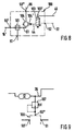
- FIG. 8 finally shows a fifth embodiment of the changeover valve device 100 according to the invention, which comprises a shuttle valve 101, a relay valve 104 and a 3/2-way valve 103 designed as a spring-loaded solenoid valve.
- shuttle valve 101 is connected with its first pressure input 50 'via line 16' to the front axle compressed air accumulator 14, while a pressure input 50 '' of relay valve 104 is connected via line 36 to the auxiliary accumulator 12.
- the shuttle valve 101 With its second pressure input, the shuttle valve 101 is connected to the pressure output of the relay valve 104 via a connecting line 61, while the pressure output 51 of the shuttle valve 101 leads to the pressure input 7 of the pressure control module 6.
- the 3/2-way valve 103 is connected to the atmosphere with its first pressure input, while its second pressure input is connected to the control pressure line 32 of the rear axle restraint circuit and its pressure output is connected via a line 44 to a control chamber 104 'of the Relay valve 104 is connected.
- the electromagnetic pilot control 103 'of the 3/2-way valve 103 is operatively connected to the central electronic control unit 20 via an electrical line 45.
- the 3/2-way valve 103 In its de-energized first position defining the rest position, the 3/2-way valve 103 shuts off the second pressure inlet with the control pressure line 32 connected to it and simultaneously connects its outlet to the atmospheric pressure present at the first pressure inlet, so that the control chamber 104 connected to this outlet 'of the relay valve 104 is vented.
- the control pressure line 32 of the rear axle restraint circuit In the energized second switching position of the 3/2-way valve 103 whose first pressure input is shut off and at the same time the control pressure line 32 of the rear axle restraint circuit is switched through to the output and thus to the control chamber 104 'of the relay valve 104, so that the control chamber 104' under the Control pressure p HA of the rear axle restraint circuit is set.
- the central electronic control unit 20 transmits an electrical control signal via line 45 to the electromagnetic pilot control 103 'of the 3/2-way valve 103 due to a pressure control valve or pressure sensor which detects the pressure drop, so that switches the 3/2-way valve 103 from its rest position into its energized second position.
- the 3/2-way valve 103 switches through the control pressure p HA of the rear axle restraint circuit present at the second pressure input to its pressure output and thus to the control chamber 104 'of the relay valve 104.
- the relay valve 104 Since the relay valve 104 is now controlled by the stepped control pressure p HA controlled by the service brake valve 15, the pressure derived from the auxiliary accumulator 12 and switched to its pressure outlet via the relay valve 104 is correspondingly stepped.
- This pressure which is stepped as a function of p HA , reaches the second pressure inlet of the shuttle valve 101 via the connecting line 61, while at the first pressure inlet 50 ′ there is insufficient pressure from the front axle compressed air reservoir 14, so that the stepped pressure p HA fed to the second pressure inlet is switched through to the pressure outlet 51 and driven into the pressure inlet 7 of the pressure control module 6.
- the switching valve device 100 between the second pressure input 50 '' and the one connected via the supply pressure line 36 Auxiliary store 12 an additional pressure limiter 107 may be arranged, its pneumatic control short-circuited with the supply pressure line is, so that at the second pressure input 50 '' a pressure level limited Supply pressure pending.
Landscapes
- Engineering & Computer Science (AREA)
- Transportation (AREA)
- Mechanical Engineering (AREA)
- Physics & Mathematics (AREA)
- Fluid Mechanics (AREA)
- Electromagnetism (AREA)
- Braking Systems And Boosters (AREA)
- Valves And Accessory Devices For Braking Systems (AREA)
Abstract
Description
Claims (11)
- Druckmittelbetätigte Fahrzeugbremsanlage mit wenigstens einem ersten Bremskreis und einem zweiten Bremskreis mit folgenden Merkmalen:a) Dem ersten Bremskreis ist wenigstens ein Bremszylinder zugeordnet, der über eine erste Steuerventileinnchtung in Abhängigkeit von einem dem ersten Bremskreis zugeordneten Steuersignal eines Mehrkreis-Bremswertgebers mit einer Druckmittelquelle für den ersten Bremskreis verbindbar ist,b) dem zweiten Bremskreis sind ein erster Bremszylinder und ein zweiter Bremszylinder zugeordnet, die über eine zweite Steuerventileinrichtung in Abhängigkeit von einem dem zweiten Bremskreis zugeordneten Steuersignal des Mehrkreis-Bremswertgebers mit einer zweiten Druckmittelquelle für den zweiten Bremskreis verbindbar sind,c) eine Umschaltventileinrichtung ist vorgesehen, die derart steuerbar ist, daß eine von der Druckmittelquelle des zweiten Bremskreises unabhängige Druckmittelquelle mit wenigstens einem Bremszylinder des zweiten Bremskreises verbindbar ist,
dadurch gekennzeichnet, daß die Umschaltventileinrichtung (100) mit einem ersten Druckeingang (50') an die dem zweiten Bremskreis zugeordnete Druckmittelquelle (14), mit einem zweiten Druckeingang (50'') an die unabhängige Druckmittelquelle (12) und mit ihrem Druckausgang (51) sowohl an einen Steuereingang (15') des Mehrkreis-Bremswertgebers (15) als auch an einen Druckeingang (7) der zweiten Steuerventileinrichtung (6) angeschlossen ist. - Druckmittelbetätigte Fahrzeugbremsanlage nach Anspruch 1, dadurch gekennzeichnet, daß die Umschaltventileinrichtung (100) wenigstens einen durch ein dem ersten Bremskreis zugeordnetes Steuersignal ansteuerbaren pneumatischen Steuereingang (52) aufweist.
- Druckmittelbetätigte Fahrzeugbremsanlage nach Anspruch 1 oder 2, dadurch gekennzeichnet, daß die Umschaltventileinrichtung (100) als Wechselventil (101) mit einem ersten und zweiten Druckeingang (50', 50'') und einem Druckausgang (51) ausgebildet ist.
- Druckmittelbetätigte Fahrzeugbremsanlage nach Anspruch 3, dadurch gekennzeichnet, daß die Umschaltventileinrichtung (100) wenigstens ein Zuschaltventil (102) umfaßt, das mit seinem Eingang zuströmseitig mit der unabhängigen Druckmittelquelle (12) und mit seinem Ausgang abströmseitig mit dem zweiten Druckeingang des Wechselventils (101) in Verbindung steht.
- Druckmittelbetätigte Fahrzeugbremsanlage nach Anspruch 4, dadurch gekennzeichnet, daß das Zuschaltventil (102) durch ein dem ersten Bremskreis zugeordnetes Steuersignal ansteuerbar ist.
- Druckmittelbetätigte Fahrzeugbremsanlage nach Anspruch 4 oder 5, dadurch gekennzeichnet, daß das Zuschaltventil (102) als Druckbegrenzer ausgebildet ist.
- Druckmittelbetätigte Fahrzeugbremsanlage nach Anspruch 1 oder 2, dadurch gekennzeichnet, daß die Umschaltventileinrichtung (100) als 3/2-Wegeventil (103) ausgebildet ist, wobei ein erster Druckeingang (50') mit der Druckmittelquelle (14) und ein zweiter Druckeingang (50'') mit der unabhängigen Druckmittelquelle (12) in Verbindung steht und in seiner Ruhestellung seinen Ausgang mit der Druckmittelquelle (14) und in seiner zweiten Stellung seinen Ausgang mit der unabhängigen Druckmittetquelle (12) verbindet.
- Druckmittelbetätigte Fahrzeugbremsanlage nach Anspruch 7, dadurch gekennzeichnet, daß an einem ersten Steuereingang (52) des 3/2-Wegeventils (103) das dem ersten Bremskreis zugeordnete Steuersignal ansteht und ein zweiter Steuereingang (170) mit der Druckmittelquelle (14) in Verbindung steht.
- Druckmittelbetätigte Fahrzeugbremsanlage nach Anspruch 7, dadurch gekennzeichnet, daß das 3/2-Wegeventil (103) als Magnetventil mit einer elektrisch betätigbaren Vorsteuerung (103') ausgebildet ist.
- Druckmittelbetätigte Fahrzeugbremsanlage nach Anspruch 9, dadurch gekennzeichnet, daß das 3/2-Wegeventil (103) im unbestromten Zustand der Vorsteuerung (103') seine Ruhestellung einnimmt und im bestromten Zustand in seine zweite Stellung wechselt.
- Druckmittelbetätigte Fahrzeugbremsanlage nach Anspruch 1, dadurch gekennzeichnet, daß die Umschaltventileinnchtung (100) wenigstens ein Wechselventil (101), ein Relaisventil (104) und ein als Magnetventil ausgebildetes 3/2-Wegeventil (103) mit zumindest zwei Schaltzuständen umfaßt, daß der erste Druckeingang (50') der Umschaltventileinrichtung (100) dem ersten Druckeingang des Wechselventils (101) und der zweite Druckeingang (50'') der Umschaltventileinrichtung (100) einem Druckeingang des Relaisventils (104) sowie der Druckausgang der Umschaltventileinrichtung (100) dem Druckausgang des Wechselventils (101) entspricht, wobei das Relaisventil (104) druckausgangsseitig mit dem zweiten Druckeingang des Wechselventils (101) verbunden ist und daß in einem von einem elektrischen Steuersignal abhängigen Schaltzustand des Magnetventils (103) ein druckeingangsseitig des Magnetventils (103) anstehendes pneumatisches Steuersignal einem Betätigungsmittel (104') des Relaisventils (104) zuschaltbar ist.
Applications Claiming Priority (2)
| Application Number | Priority Date | Filing Date | Title |
|---|---|---|---|
| DE19933483 | 1999-07-16 | ||
| DE19933483A DE19933483C1 (de) | 1999-07-16 | 1999-07-16 | Druckmittelbetätigte Fahrzeugbremsanlage |
Publications (3)
| Publication Number | Publication Date |
|---|---|
| EP1069015A2 true EP1069015A2 (de) | 2001-01-17 |
| EP1069015A3 EP1069015A3 (de) | 2002-08-28 |
| EP1069015B1 EP1069015B1 (de) | 2003-11-26 |
Family
ID=7915078
Family Applications (1)
| Application Number | Title | Priority Date | Filing Date |
|---|---|---|---|
| EP00111081A Expired - Lifetime EP1069015B1 (de) | 1999-07-16 | 2000-06-02 | Druckmittelbetätigte Fahrzeugbremsanlage |
Country Status (2)
| Country | Link |
|---|---|
| EP (1) | EP1069015B1 (de) |
| DE (2) | DE19933483C1 (de) |
Cited By (4)
| Publication number | Priority date | Publication date | Assignee | Title |
|---|---|---|---|---|
| US9421961B2 (en) | 2012-02-16 | 2016-08-23 | Knorr-Bremse Systeme Fuer Nutzfahrzeuge Gmbh | Method for determining a brake pressure value on the basis of characteristic curves |
| WO2019192861A1 (de) * | 2018-04-05 | 2019-10-10 | Wabco Gmbh | Elektropneumatischer zweikanalachsmodulator mit einem kanal für die vorderachse und einem kanal für die hinterachse |
| CN116691630A (zh) * | 2023-06-13 | 2023-09-05 | 中国重汽集团济南动力有限公司 | 一种提升车型后桥制动控制系统及方法 |
| WO2024235658A1 (de) * | 2023-05-12 | 2024-11-21 | Daimler Truck AG | Druckluft-bremsvorrichtung und kraftfahrzeug mit einer solchen druckluft-bremsvorrichtung |
Families Citing this family (8)
| Publication number | Priority date | Publication date | Assignee | Title |
|---|---|---|---|---|
| DE19935979C2 (de) * | 1999-07-30 | 2001-07-19 | Knorr Bremse Systeme | Druckmittelbetätigte Fahrzeugbremsanlage |
| DE10004086C2 (de) * | 2000-01-31 | 2001-12-06 | Knorr Bremse Systeme | Bremsanlage für Fahrzeuge, insbesondere Nutzfahrzeuge |
| DE10130541A1 (de) * | 2001-06-25 | 2003-01-09 | Knorr Bremse Systeme | Kombinierte elektro-pneumatisch und mechanisch betätigbare Ventileinrichtung und Steuervorrichtung für ein Bremssystem |
| DE10230314B4 (de) * | 2002-07-05 | 2013-10-24 | Iveco Magirus Ag | Bremsvorrichtung für Fahrzeuge, insbesondere Lastkraftwagen |
| RU2248284C1 (ru) * | 2004-04-15 | 2005-03-20 | Открытое акционерное общество МТЗ ТРАНСМАШ | Воздухораспределитель тормоза железнодорожного транспортного средства |
| DE102007004759B4 (de) * | 2007-01-31 | 2010-09-30 | Knorr-Bremse Systeme für Nutzfahrzeuge GmbH | Bremsanlage und Verfahren zum Steuern einer Bremsanlage für ein Nutzfahrzeug |
| DE102008035335A1 (de) * | 2008-07-29 | 2010-02-04 | Man Nutzfahrzeuge Aktiengesellschaft | Druckmittelbetätigte Bremsvorrichtung für Kraftfahrzeuge |
| WO2013093545A1 (en) | 2011-12-23 | 2013-06-27 | Renault Trucks | Electronically controlled pneumatic brake system for an automotive vehicle and automotive vehicle equipped with such a system |
Citations (1)
| Publication number | Priority date | Publication date | Assignee | Title |
|---|---|---|---|---|
| EP0726190A1 (de) | 1995-02-10 | 1996-08-14 | WABCO GmbH | Druckmittelbetätigte Fahrzeugbremsanlage |
Family Cites Families (2)
| Publication number | Priority date | Publication date | Assignee | Title |
|---|---|---|---|---|
| DE19504394C1 (de) * | 1995-02-10 | 1996-03-07 | Wabco Gmbh | Druckmittelbetätigte Fahrzeugbremsanlage |
| DE19514603C2 (de) * | 1995-04-20 | 1997-04-03 | Daimler Benz Ag | Druckluft-Bremsanlage für ein Nutzfahrzeug |
-
1999
- 1999-07-16 DE DE19933483A patent/DE19933483C1/de not_active Expired - Fee Related
-
2000
- 2000-06-02 EP EP00111081A patent/EP1069015B1/de not_active Expired - Lifetime
- 2000-06-02 DE DE50004538T patent/DE50004538D1/de not_active Expired - Lifetime
Patent Citations (1)
| Publication number | Priority date | Publication date | Assignee | Title |
|---|---|---|---|---|
| EP0726190A1 (de) | 1995-02-10 | 1996-08-14 | WABCO GmbH | Druckmittelbetätigte Fahrzeugbremsanlage |
Cited By (7)
| Publication number | Priority date | Publication date | Assignee | Title |
|---|---|---|---|---|
| US9421961B2 (en) | 2012-02-16 | 2016-08-23 | Knorr-Bremse Systeme Fuer Nutzfahrzeuge Gmbh | Method for determining a brake pressure value on the basis of characteristic curves |
| WO2019192861A1 (de) * | 2018-04-05 | 2019-10-10 | Wabco Gmbh | Elektropneumatischer zweikanalachsmodulator mit einem kanal für die vorderachse und einem kanal für die hinterachse |
| CN111867905A (zh) * | 2018-04-05 | 2020-10-30 | 威伯科有限公司 | 具有前桥通道和后桥通道的电动气动的双通道车桥调制器 |
| CN111867905B (zh) * | 2018-04-05 | 2022-08-16 | 威伯科有限公司 | 具有前桥通道和后桥通道的电动气动的双通道车桥调制器 |
| US11945420B2 (en) | 2018-04-05 | 2024-04-02 | Zf Cv Systems Europe Bv | Electro-pneumatic two-channel axle modulator |
| WO2024235658A1 (de) * | 2023-05-12 | 2024-11-21 | Daimler Truck AG | Druckluft-bremsvorrichtung und kraftfahrzeug mit einer solchen druckluft-bremsvorrichtung |
| CN116691630A (zh) * | 2023-06-13 | 2023-09-05 | 中国重汽集团济南动力有限公司 | 一种提升车型后桥制动控制系统及方法 |
Also Published As
| Publication number | Publication date |
|---|---|
| DE19933483C1 (de) | 2000-10-26 |
| EP1069015B1 (de) | 2003-11-26 |
| DE50004538D1 (de) | 2004-01-08 |
| EP1069015A3 (de) | 2002-08-28 |
Similar Documents
| Publication | Publication Date | Title |
|---|---|---|
| DE102007038472B4 (de) | Ventilanordnung zur Steuerung einer Bremsanlage eines Anhängerfahrzeugs | |
| DE102017005979A1 (de) | Elektro-Pneumatische Handbremse (EPH) mit integrierten TCV (skandinavische Ansteuerung | |
| EP0738640B1 (de) | Druckluft-Bremsanlage für ein Nutzfahrzeug | |
| EP3414138B1 (de) | Relaisventileinrichtung einer pneumatischen oder elektro-pneumatischen kraftfahrzeugbremseinrichtung | |
| EP2133250A1 (de) | Parkbremsventilanordnung für ein Bremssystem eines Nutzfahrzeuges | |
| DE19918070B4 (de) | Druckregelvorrichtung für elektro-pneumatische Bremsanlagen von Fahrzeugen, insbesondere Nutzfahrzeugen | |
| EP0478953B1 (de) | Elektropneumatische Bremsanlage | |
| EP1069015B1 (de) | Druckmittelbetätigte Fahrzeugbremsanlage | |
| EP1220772B1 (de) | Druckmittelbetätigte fahrzeugbremsanlage | |
| EP1185447B1 (de) | Druckmittelbetätigte fahrzeugbremsanlage | |
| EP3277551B1 (de) | Drucklufteinrichtung für fahrzeuge mit doppelrelaisventil | |
| EP2371641A2 (de) | Pneumatisch vorgesteuertes Anhängersteuermodul mit beiden Steuerkammern vorgeordnetem Backup-Ventil | |
| DE19932470B4 (de) | Druckmittelbetätigte Fahrzeugbremsanlage | |
| EP4237298B1 (de) | Elektropneumatische einrichtung mit einer schutzventileinheit | |
| EP1069016B1 (de) | Druckmittelbetätigte Fahrzeugbremsanlage | |
| DE10042215C5 (de) | Druckmittelbetätigte Fahrzeugbremsanlage mit redundanter Ansteuerung wenigstens eines Bremszylinders | |
| EP1099611B1 (de) | Druckmittelbetätigte Fahrzeugbremsanlage | |
| DE10139748A1 (de) | Anhängerbremsventil für einen Anhänger mit elektronischer Bremsregelung | |
| DE10139757A1 (de) | Anhängerbremsventil für Anhängefahrzeuge mit elektronischer Bremsregelung und erweiterter Sicherheit des geparkten Anhängers | |
| EP1530530B1 (de) | Elektronisches bremssystem, insbesondere für nutzfathrzeuganhänger | |
| EP1188635B1 (de) | Anhängerbremsventil für einen Anhänger mit elektronischer Bremsregelung |
Legal Events
| Date | Code | Title | Description |
|---|---|---|---|
| PUAI | Public reference made under article 153(3) epc to a published international application that has entered the european phase |
Free format text: ORIGINAL CODE: 0009012 |
|
| AK | Designated contracting states |
Kind code of ref document: A2 Designated state(s): AT BE CH CY DE DK ES FI FR GB GR IE IT LI LU MC NL PT SE |
|
| AX | Request for extension of the european patent |
Free format text: AL;LT;LV;MK;RO;SI |
|
| PUAL | Search report despatched |
Free format text: ORIGINAL CODE: 0009013 |
|
| AK | Designated contracting states |
Kind code of ref document: A3 Designated state(s): AT BE CH CY DE DK ES FI FR GB GR IE IT LI LU MC NL PT SE |
|
| AX | Request for extension of the european patent |
Free format text: AL;LT;LV;MK;RO;SI |
|
| 17P | Request for examination filed |
Effective date: 20030228 |
|
| GRAH | Despatch of communication of intention to grant a patent |
Free format text: ORIGINAL CODE: EPIDOS IGRA |
|
| AKX | Designation fees paid |
Designated state(s): DE FR SE |
|
| GRAS | Grant fee paid |
Free format text: ORIGINAL CODE: EPIDOSNIGR3 |
|
| GRAA | (expected) grant |
Free format text: ORIGINAL CODE: 0009210 |
|
| AK | Designated contracting states |
Kind code of ref document: B1 Designated state(s): DE FR SE |
|
| REG | Reference to a national code |
Ref country code: SE Ref legal event code: TRGR |
|
| REF | Corresponds to: |
Ref document number: 50004538 Country of ref document: DE Date of ref document: 20040108 Kind code of ref document: P |
|
| REG | Reference to a national code |
Ref country code: IE Ref legal event code: FG4D Free format text: GERMAN |
|
| PGFP | Annual fee paid to national office [announced via postgrant information from national office to epo] |
Ref country code: SE Payment date: 20040604 Year of fee payment: 5 |
|
| PGFP | Annual fee paid to national office [announced via postgrant information from national office to epo] |
Ref country code: FR Payment date: 20040608 Year of fee payment: 5 |
|
| REG | Reference to a national code |
Ref country code: IE Ref legal event code: FD4D |
|
| ET | Fr: translation filed | ||
| PLBE | No opposition filed within time limit |
Free format text: ORIGINAL CODE: 0009261 |
|
| STAA | Information on the status of an ep patent application or granted ep patent |
Free format text: STATUS: NO OPPOSITION FILED WITHIN TIME LIMIT |
|
| 26N | No opposition filed |
Effective date: 20040827 |
|
| PG25 | Lapsed in a contracting state [announced via postgrant information from national office to epo] |
Ref country code: SE Free format text: LAPSE BECAUSE OF NON-PAYMENT OF DUE FEES Effective date: 20050603 |
|
| EUG | Se: european patent has lapsed | ||
| PG25 | Lapsed in a contracting state [announced via postgrant information from national office to epo] |
Ref country code: FR Free format text: LAPSE BECAUSE OF NON-PAYMENT OF DUE FEES Effective date: 20060228 |
|
| REG | Reference to a national code |
Ref country code: FR Ref legal event code: ST Effective date: 20060228 |
|
| PGFP | Annual fee paid to national office [announced via postgrant information from national office to epo] |
Ref country code: DE Payment date: 20120827 Year of fee payment: 13 |
|
| REG | Reference to a national code |
Ref country code: DE Ref legal event code: R119 Ref document number: 50004538 Country of ref document: DE Effective date: 20140101 |
|
| PG25 | Lapsed in a contracting state [announced via postgrant information from national office to epo] |
Ref country code: DE Free format text: LAPSE BECAUSE OF NON-PAYMENT OF DUE FEES Effective date: 20140101 |