EP1068912A2 - Hypoid ring gear for differentials and method of producing the same - Google Patents
Hypoid ring gear for differentials and method of producing the same Download PDFInfo
- Publication number
- EP1068912A2 EP1068912A2 EP99308827A EP99308827A EP1068912A2 EP 1068912 A2 EP1068912 A2 EP 1068912A2 EP 99308827 A EP99308827 A EP 99308827A EP 99308827 A EP99308827 A EP 99308827A EP 1068912 A2 EP1068912 A2 EP 1068912A2
- Authority
- EP
- European Patent Office
- Prior art keywords
- intermediate article
- forging
- end product
- outer diameters
- hypoid
- Prior art date
- Legal status (The legal status is an assumption and is not a legal conclusion. Google has not performed a legal analysis and makes no representation as to the accuracy of the status listed.)
- Granted
Links
Images


Classifications
-
- B—PERFORMING OPERATIONS; TRANSPORTING
- B21—MECHANICAL METAL-WORKING WITHOUT ESSENTIALLY REMOVING MATERIAL; PUNCHING METAL
- B21J—FORGING; HAMMERING; PRESSING METAL; RIVETING; FORGE FURNACES
- B21J9/00—Forging presses
- B21J9/02—Special design or construction
- B21J9/025—Special design or construction with rolling or wobbling dies
-
- B—PERFORMING OPERATIONS; TRANSPORTING
- B21—MECHANICAL METAL-WORKING WITHOUT ESSENTIALLY REMOVING MATERIAL; PUNCHING METAL
- B21K—MAKING FORGED OR PRESSED METAL PRODUCTS, e.g. HORSE-SHOES, RIVETS, BOLTS OR WHEELS
- B21K1/00—Making machine elements
- B21K1/28—Making machine elements wheels; discs
- B21K1/30—Making machine elements wheels; discs with gear-teeth
-
- Y—GENERAL TAGGING OF NEW TECHNOLOGICAL DEVELOPMENTS; GENERAL TAGGING OF CROSS-SECTIONAL TECHNOLOGIES SPANNING OVER SEVERAL SECTIONS OF THE IPC; TECHNICAL SUBJECTS COVERED BY FORMER USPC CROSS-REFERENCE ART COLLECTIONS [XRACs] AND DIGESTS
- Y10—TECHNICAL SUBJECTS COVERED BY FORMER USPC
- Y10T—TECHNICAL SUBJECTS COVERED BY FORMER US CLASSIFICATION
- Y10T29/00—Metal working
- Y10T29/49—Method of mechanical manufacture
- Y10T29/49462—Gear making
- Y10T29/49467—Gear shaping
- Y10T29/49472—Punching or stamping
-
- Y—GENERAL TAGGING OF NEW TECHNOLOGICAL DEVELOPMENTS; GENERAL TAGGING OF CROSS-SECTIONAL TECHNOLOGIES SPANNING OVER SEVERAL SECTIONS OF THE IPC; TECHNICAL SUBJECTS COVERED BY FORMER USPC CROSS-REFERENCE ART COLLECTIONS [XRACs] AND DIGESTS
- Y10—TECHNICAL SUBJECTS COVERED BY FORMER USPC
- Y10T—TECHNICAL SUBJECTS COVERED BY FORMER US CLASSIFICATION
- Y10T29/00—Metal working
- Y10T29/49—Method of mechanical manufacture
- Y10T29/49462—Gear making
- Y10T29/49467—Gear shaping
- Y10T29/49474—Die-press shaping
-
- Y—GENERAL TAGGING OF NEW TECHNOLOGICAL DEVELOPMENTS; GENERAL TAGGING OF CROSS-SECTIONAL TECHNOLOGIES SPANNING OVER SEVERAL SECTIONS OF THE IPC; TECHNICAL SUBJECTS COVERED BY FORMER USPC CROSS-REFERENCE ART COLLECTIONS [XRACs] AND DIGESTS
- Y10—TECHNICAL SUBJECTS COVERED BY FORMER USPC
- Y10T—TECHNICAL SUBJECTS COVERED BY FORMER US CLASSIFICATION
- Y10T29/00—Metal working
- Y10T29/49—Method of mechanical manufacture
- Y10T29/49462—Gear making
- Y10T29/49467—Gear shaping
- Y10T29/49478—Gear blank making
Definitions
- the present invention relates to a hypoid ring gear for FR (front engine rear drive) vehicle differentials and a method of producing the same.
- hypoid ring gear for differentials
- Fig. 6 This type of hypoid ring gear for differentials
- Fig. 6 This type of hypoid ring gear for differentials
- Fig. 6 by heating a round rod blank A1, upset-forging it to forma first disk-like intermediate article A2, die-forging said first intermediate article A2 to form a second intermediate article A3 in the form of a bottom-closed annular body having substantially the same inner and outer diameters as the end product, punching out the bottom A3' of said second intermediate article A3 to form a third intermediate article A4 in the form of a bottom-opened annular body, normalizing and shot-blasting said third intermediate article A4, lathing said third intermediate article A4 as by an NC lathe to form a fourth intermediate article A5 in the form of a crude product, roughly gear-cutting said fourth intermediate article A5 on a Gleason gear cutting machine for rough machining, and finish-gear-cutting it on a Gleason gear cutting machine for finish machining,
- the conventional method of producing hypoid ring gears includes the step of directly die-forging the first disk-like intermediate article A2 to form said second intermediate article A3 in the form of a bottom-closed annular body having substantially the same inner and outer diameters as the end product A6, it needs a large-sized forge press. Besides this, it has to use two expensive Gleason gear cutting machines for cutting hypoid teeth g , thus presenting the drawback of the installation cost being very high. Further, since hypoid teeth g are formed by cutting , there are drawbacks in that the allowance for cutting (the amount to be lathed and the amount to be cut for tooth formation) increases, thus not only decreasing the yield of material but also prolonging the cutting time, thereby increasing the running cost.
- a hypoid ring gear produced by the conventional method has its hypoid teeth g formed by cutting, with the result that the flow of metal in the hypoid teeth g has been cut away by the cutter, thus decreasing the tooth surface strength. Therefore, a larger hypoid ring gear is required for transmission of a heavier load, thus presenting the drawback that the differential has to be increased in size.
- the present invention has been proposed with the above drawback in the prior art in mind, and its object is to provide a hypoid ring gear for differentials and a method of producing the same, which are capable of reducing the installation cost and the running cost, minimizing the production cost and improving the tooth surface strength of the hypoid gear.
- hypoid ring gears for differentials characterised by the step of orbitally forging a crude product slightly smaller in inner and outer diameters and slightly larger in axial thickness than the end product to form the end product having hypoid teeth formed therein.
- annular blank smaller in inner and outer diameters and larger in axial thickness than the end product is subjected to ring-rolling to form the crude product.
- a preferred method of producing hypoid ring gears for differentials comprises the steps of upset-forging a round bar blank heated to a predetermined temperature to form a first disk-like intermediate article, die-forging said first intermediate article to form a second intermediate article in the form of a bottom-closed annular body which is smaller in inner and outer diameters and larger in axial thickness than the end product, punching out the bottom of said second intermediate article to form a third intermediate article in the form of a bottom-opened annular body which is smaller in inner and outer diameters and larger in axial thickness than the end product, shot-blasting said third intermediate article to remove the scale and then reheating it to a predetermined temperature and ring-rolling it to form a fourth intermediate article in the form of a crude product which is somewhat smaller in inner and outer diameters and somewhat larger in axial thickness than the end product, orbitally forging said fourth intermediate article to form a fifth intermediate article having hypoid teeth formed therein, normalising and shot-blasting said fifth intermediate article to effect normal
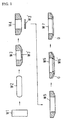
- Fig. 1 is a process-explanatory view showing a method of producing hypoid ring gears according to the present invention.
- the method of producing hypoid ring gears according to the invention includes the steps of first heating a round bar blank W1 cut to a fixed length to a predetermined temperature (e.g., 1,200°C) by an induction heater, and upset-forging it by a forge press to form a first disk-like intermediate article W2 . Then follows the step of die-forging said first intermediate article W2 by a forge press to form a second intermediate article W3 in the form of a bottom-closed annular body which is smaller in inner and outer diameters and larger in axial thickness than the end product.
- a predetermined temperature e.g. 1,200°C
- the aforesaid forge press comprises a plurality of equispaced punches and dies operatively associated with each other to perform their forming operation, with a transfer feeder used to feed parts to be forged successively to the operating position of the punch and die.
- a round bar blank W1 heated to a predetermined temperature by an induction heater 1 is upset-forged using an upsetting set of punch 2 and die 3 to form a first disk-like intermediate article W2.
- This first intermediate article W2 is die-formed by a punch 4 and a die 5 which are smaller in inner and outer diameters than the end product to form a second intermediate article W3 in the form of a bottom-closed annular body which is smaller in inner and outer diameters and larger in axial thickness than the end product.
- the bottom W3' of the second intermediate article W3 is punched out by a punching-out set of punch 6 and die 7 to form a third intermediate article W4 in the form of a bottom-openedbody which is smaller in inner and outer diameters and larger in axial thickness than the end product.
- the aforesaid rolling machine as shown in Fig. 3, comprises a forming roll 8 supported for being driven for rotation and having on its inner peripheral surface a shape which is the same as the outer peripheral shape of the fourth intermediate article W5, a mandrel 9 supported for rotation and for radial slide movement and having on its outer peripheral surface a shape which is the same as the inner peripheral shape of the fourth intermediate article W5, and a pair of mandrel support rolls 10 for the radial sliding under pressure of the mandrel 9 through a pressure applying means (not shown), wherein with the third intermediate article W4 held between the forming roll 8 and the mandrel 9, the forming roll 8 is rotated to cause the contact rotation of the third intermediate article W4 while the mandrel 9 is radially slid under pressure by the mandrel support rolls 10 to apply a radial holding pressure to the third intermediate article W4, whereby the latter is ring-rolled by the forming roll 8 and mandrel 9 to form the forth intermediate article W5 which is somewhat smaller in inner
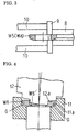
- the aforesaid orbital forging machine as shown in Fig. 4, comprises a pressure-forming die 11 having a pressure-forming surface 11a conforming in outer shape to the end product and installed so that it can be raised and lowered by pressure applying means (not shown), and a punch 12 having a conical pressing surface 12a and adapted to be rotated while orbiting along a circumference with its center axis inclined with respect to the center axis of the pressure-forming die 11, the arrangement being such that with the fourth intermediate article W5 fed into the pressure-forming die 11 and with the punch 12 rotating while orbiting along a circumference, the pressure-forming die 11 is raised to urge the fourth intermediate article W5 against the pressing surface 12a of the punch 12, whereupon the punch 12 locally urges the fourth intermediate article W5 against the pressure-forming surface 11a of the pressure-forming die 11 to progressively circumferentially press it, thereby leaving the impression of the pressure-rolling surface 11a of the pressure-forming die 11 on the fourth intermediate article W5, thus forming the fifth intermediate article W6 having
- the aforesaid punching machine as shown in Fig. 5, comprises a die 13 having an inner shape conforming in outer shape to the end product and a punch 14 having a diameter which is the same as the inner diameter of the end product, the arrangement being such that the punch 14 is urged into the fifth intermediate article W6 fed into the die 13, whereby the fifth intermediate article W6 has its inner burr W6', which is formed thereon during tooth forming operation based on orbital forging, punched out by the punch 14 and is cold-coined to provide the end product W7.
- the hypoid ring gear producing method of the present invention includes the steps of forming the first disk-like intermediate article W2 into the second intermediate article W3 in the form of a bottom-closed body which is smaller in inner and outer diameters and larger in axial thickness than the end product, punching out the bottom W3' of the second intermediate article W3 while securing the condition in which the inner and outer diameters are smaller than those of the end product and the axial thickness is larger than that of the end product, and ring-rolling it to form the fourth intermediate article W5 in the form of a crude product which is somewhat smaller in inner and outer diameters and somewhat larger in axial thickness than the end product; therefore, the large-sized forge press is no longer necessary and the installation cost can be reduced.
- hypoid teeth G are generated by locally pressing the pressure-forming surface 11a of the pressure-forming die 11 against the fourth intermediate article W5 so as to circumferentially and progressively press the press-rolling surface 11a of the pressure-forming die 11 against the forth intermediate article W5, thereby leaving the impression of the pressure-rolling surface 11a of the pressure-forming die 11 on the fourth intermediate article W5; therefore, as compared with the conventional tooth cutting using two Gleason gear cutting machines, the installation cost can be reduced while increasing the yield of material and reducing the processing time and the running cost.
- hypoid ring gear produced by the present production method has hypoid teeth G formed by orbital forging, the hypoid teeth G are formed with flow of grains extending along the tooth surface, so that the tooth surface strength is considerably increased as compared with that of hypoid teeth formed by cutting.
- a heavier load can be transmitted with a smaller hypoid gear, so that size-reduction of the differential is possible.
- the processing time can be reduced and so can be the running cost.
- hypoid ring gears which is capable of decreasing the installation cost and running cost and minimizing the production cost, and to provide a hypoid ring gear having the tooth surface strength of the hypoid teeth increased to the extent of enabling the differential to be reduced in size.
Landscapes
- Engineering & Computer Science (AREA)
- Mechanical Engineering (AREA)
- Forging (AREA)
- Gears, Cams (AREA)
Abstract
Description
- The present invention relates to a hypoid ring gear for FR (front engine rear drive) vehicle differentials and a method of producing the same.
- This type of hypoid ring gear for differentials (hereinafter referred to as the hypoid ring gear) has heretofore been produced, as shown in Fig. 6, by heating a round rod blank A1, upset-forging it to forma first disk-like intermediate article A2, die-forging said first intermediate article A2 to form a second intermediate article A3 in the form of a bottom-closed annular body having substantially the same inner and outer diameters as the end product, punching out the bottom A3' of said second intermediate article A3 to form a third intermediate article A4 in the form of a bottom-opened annular body, normalizing and shot-blasting said third intermediate article A4, lathing said third intermediate article A4 as by an NC lathe to form a fourth intermediate article A5 in the form of a crude product, roughly gear-cutting said fourth intermediate article A5 on a Gleason gear cutting machine for rough machining, and finish-gear-cutting it on a Gleason gear cutting machine for finish machining, thereby providing an end product A6 having hypoid teeth g cut therein.
- Since the conventional method of producing hypoid ring gears includes the step of directly die-forging the first disk-like intermediate article A2 to form said second intermediate article A3 in the form of a bottom-closed annular body having substantially the same inner and outer diameters as the end product A6, it needs a large-sized forge press. Besides this, it has to use two expensive Gleason gear cutting machines for cutting hypoid teeth g, thus presenting the drawback of the installation cost being very high. Further, since hypoid teeth g are formed by cutting , there are drawbacks in that the allowance for cutting (the amount to be lathed and the amount to be cut for tooth formation) increases, thus not only decreasing the yield of material but also prolonging the cutting time, thereby increasing the running cost.
- Further, a hypoid ring gear produced by the conventional method has its hypoid teeth g formed by cutting, with the result that the flow of metal in the hypoid teeth g has been cut away by the cutter, thus decreasing the tooth surface strength. Therefore, a larger hypoid ring gear is required for transmission of a heavier load, thus presenting the drawback that the differential has to be increased in size.
- The present invention has been proposed with the above drawback in the prior art in mind, and its object is to provide a hypoid ring gear for differentials and a method of producing the same, which are capable of reducing the installation cost and the running cost, minimizing the production cost and improving the tooth surface strength of the hypoid gear.
- According to the present invention, there is provided a method of producing hypoid ring gears for differentials, characterised by the step of orbitally forging a crude product slightly smaller in inner and outer diameters and slightly larger in axial thickness than the end product to form the end product having hypoid teeth formed therein.
- Preferably prior to the orbital forging, or rocking die forging, an annular blank smaller in inner and outer diameters and larger in axial thickness than the end product is subjected to ring-rolling to form the crude product.
- A preferred method of producing hypoid ring gears for differentials according to the present invention, comprises the steps of upset-forging a round bar blank heated to a predetermined temperature to form a first disk-like intermediate article, die-forging said first intermediate article to form a second intermediate article in the form of a bottom-closed annular body which is smaller in inner and outer diameters and larger in axial thickness than the end product, punching out the bottom of said second intermediate article to form a third intermediate article in the form of a bottom-opened annular body which is smaller in inner and outer diameters and larger in axial thickness than the end product, shot-blasting said third intermediate article to remove the scale and then reheating it to a predetermined temperature and ring-rolling it to form a fourth intermediate article in the form of a crude product which is somewhat smaller in inner and outer diameters and somewhat larger in axial thickness than the end product, orbitally forging said fourth intermediate article to form a fifth intermediate article having hypoid teeth formed therein, normalising and shot-blasting said fifth intermediate article to effect normalisation and scale removal, punching out the internal burr formed on said fifth intermediate article during tooth forming operation based on orbital forging, and cold-coining thereby forming the end product.
-
- Fig. 1 is a view explaining a process for producing hypoid ring gears for differentials according to the present invention;
- Fig. 2 is a schematic explanatory view of a forge press used in the invention;
- Fig. 3 is a schematic explanatory view of a rolling machine used in the invention;
- Fig. 4 is a schematic explanatory view of an orbital forging machine used in the invention;
- Fig. 5 is a schematic explanatory view of a punching machine used in the invention; and
- Fig. 6 is a view explaining the conventional process for producing hypoid ring gears for differentials.
-
- Fig. 1 is a process-explanatory view showing a method of producing hypoid ring gears according to the present invention. The method of producing hypoid ring gears according to the invention includes the steps of first heating a round bar blank W1 cut to a fixed length to a predetermined temperature (e.g., 1,200°C) by an induction heater, and upset-forging it by a forge press to form a first disk-like intermediate article W2 . Then follows the step of die-forging said first intermediate article W2 by a forge press to form a second intermediate article W3 in the form of a bottom-closed annular body which is smaller in inner and outer diameters and larger in axial thickness than the end product. Then follows the step of punching out the bottom W3' of said second intermediate article W3 by a forge press to forma third intermediate article W4 in the formof a bottom-opened annular body which is smaller in inner and outer diameters and larger in axial thickness than the end product. Then follows the step of shot-blasting said third intermediate article W4 to remove the scale and then reheating said third intermediate article W4 to a predetermined temperature (e.g., 900 - 950°C) by an induction heater and ring-rolling it by a ring-rolling machine to form a fourth intermediate article W5 in the form of a crude product which is somewhat smaller in inner and outer diameters and somewhat larger in axial thickness than the end product. Then follows the step of orbitally forging said fourth intermediate article W5 by an orbital forging machine to form a fifth intermediate article W6 having hypoid teeth G formed therein by orbital forging. Then follows the step of normalizing and shot-blasting said fifth intermediate article W6 to effect normalization and scale removal and then punching out by a punching machine the internal burr W6' formed on said fifth intermediate article W6 during tooth forming operation based on orbital forging, and cold-coining it to form the end product W7.
- The aforesaid forge press comprises a plurality of equispaced punches and dies operatively associated with each other to perform their forming operation, with a transfer feeder used to feed parts to be forged successively to the operating position of the punch and die. Thus, as shown in Fig. 2, a round bar blank W1 heated to a predetermined temperature by an
induction heater 1 is upset-forged using an upsetting set ofpunch 2 and die 3 to form a first disk-like intermediate article W2. This first intermediate article W2 is die-formed by apunch 4 and adie 5 which are smaller in inner and outer diameters than the end product to form a second intermediate article W3 in the form of a bottom-closed annular body which is smaller in inner and outer diameters and larger in axial thickness than the end product. The bottom W3' of the second intermediate article W3 is punched out by a punching-out set of punch 6 and die 7 to form a third intermediate article W4 in the form of a bottom-openedbody which is smaller in inner and outer diameters and larger in axial thickness than the end product. - The aforesaid rolling machine, as shown in Fig. 3, comprises a forming
roll 8 supported for being driven for rotation and having on its inner peripheral surface a shape which is the same as the outer peripheral shape of the fourth intermediate article W5, amandrel 9 supported for rotation and for radial slide movement and having on its outer peripheral surface a shape which is the same as the inner peripheral shape of the fourth intermediate article W5, and a pair ofmandrel support rolls 10 for the radial sliding under pressure of themandrel 9 through a pressure applying means (not shown), wherein with the third intermediate article W4 held between the formingroll 8 and themandrel 9, the formingroll 8 is rotated to cause the contact rotation of the third intermediate article W4 while themandrel 9 is radially slid under pressure by themandrel support rolls 10 to apply a radial holding pressure to the third intermediate article W4, whereby the latter is ring-rolled by the formingroll 8 andmandrel 9 to form the forth intermediate article W5 which is somewhat smaller in inner and outer diameters and somewhat larger in axial thickness than the end product. - The aforesaid orbital forging machine, as shown in Fig. 4, comprises a pressure-forming die 11 having a pressure-forming surface 11a conforming in outer shape to the end product and installed so that it can be raised and lowered by pressure applying means (not shown), and a
punch 12 having a conical pressing surface 12a and adapted to be rotated while orbiting along a circumference with its center axis inclined with respect to the center axis of the pressure-formingdie 11, the arrangement being such that with the fourth intermediate article W5 fed into the pressure-formingdie 11 and with thepunch 12 rotating while orbiting along a circumference, the pressure-formingdie 11 is raised to urge the fourth intermediate article W5 against the pressing surface 12a of thepunch 12, whereupon thepunch 12 locally urges the fourth intermediate article W5 against the pressure-forming surface 11a of the pressure-formingdie 11 to progressively circumferentially press it, thereby leaving the impression of the pressure-rolling surface 11a of the pressure-forming die 11 on the fourth intermediate article W5, thus forming the fifth intermediate article W6 having hypoid teeth G formed therein by orbital forging. - The aforesaid punching machine, as shown in Fig. 5, comprises a die 13 having an inner shape conforming in outer shape to the end product and a
punch 14 having a diameter which is the same as the inner diameter of the end product, the arrangement being such that thepunch 14 is urged into the fifth intermediate article W6 fed into the die 13, whereby the fifth intermediate article W6 has its inner burr W6', which is formed thereon during tooth forming operation based on orbital forging, punched out by thepunch 14 and is cold-coined to provide the end product W7. - The hypoid ring gear producing method of the present invention includes the steps of forming the first disk-like intermediate article W2 into the second intermediate article W3 in the form of a bottom-closed body which is smaller in inner and outer diameters and larger in axial thickness than the end product, punching out the bottom W3' of the second intermediate article W3 while securing the condition in which the inner and outer diameters are smaller than those of the end product and the axial thickness is larger than that of the end product, and ring-rolling it to form the fourth intermediate article W5 in the form of a crude product which is somewhat smaller in inner and outer diameters and somewhat larger in axial thickness than the end product; therefore, the large-sized forge press is no longer necessary and the installation cost can be reduced. Further, the hypoid teeth G are generated by locally pressing the pressure-forming surface 11a of the pressure-forming die 11 against the fourth intermediate article W5 so as to circumferentially and progressively press the press-rolling surface 11a of the pressure-forming die 11 against the forth intermediate article W5, thereby leaving the impression of the pressure-rolling surface 11a of the pressure-forming die 11 on the fourth intermediate article W5; therefore, as compared with the conventional tooth cutting using two Gleason gear cutting machines, the installation cost can be reduced while increasing the yield of material and reducing the processing time and the running cost.
- Further, since the hypoid ring gear produced by the present production method has hypoid teeth G formed by orbital forging, the hypoid teeth G are formed with flow of grains extending along the tooth surface, so that the tooth surface strength is considerably increased as compared with that of hypoid teeth formed by cutting. Thus, a heavier load can be transmitted with a smaller hypoid gear, so that size-reduction of the differential is possible. Furthermore, as compared with the case of cutting teeth by a Gleason gear-cutting machine, the processing time can be reduced and so can be the running cost.
- As has been described so far, according to the present invention, it is possible to provide a method of producing hypoid ring gears which is capable of decreasing the installation cost and running cost and minimizing the production cost, and to provide a hypoid ring gear having the tooth surface strength of the hypoid teeth increased to the extent of enabling the differential to be reduced in size.
Claims (4)
- A method of producing hypoid ring gears for differentials, characterised by the step of orbitally forging a crude product slightly smaller in inner and outer diameters and slightly larger in axial thickness than the end product to form the end product having hypoid teeth formed therein.
- A method according to claim 1, characterised in that prior to the orbital forging, or rocking die forging, an annular blank smaller in inner and outer diameters and larger in axial thickness than the end product is subjected to ring-rolling to form the crude product.
- A method of producing hypoid ring gears for differentials according to claim 1, comprising the steps ofupset-forging a round bar blank heated to a predetermined temperature to form a first disk-like intermediate article,die-forging said first intermediate article to form a second intermediate article in the form of a bottom-closed annular body which is smaller in inner and outer diameters and large in axial thickness than the end product,punching out the bottom of said second intermediate article to form a third intermediate article in the form of a bottom-opened annular body which is smaller in inner and outer diameters and larger in axial thickness than the end product,shot-blasting said third intermediate article to remove the scale and reheating it to a predetermined temperature and ring-rolling it to form a fourth intermediate article in the form of a crude product which is somewhat smaller in inner and outer diameters and somewhat larger in axial thickness than the end product,orbitally forging said fourth intermediate article to form a fifth intermediate article having hypoid teeth formed therein, andnormalising and shot-blasting said fifth intermediate article to effect normalisation and scale removal and then punching out the inner burr which is formed on said fifth intermediate article during tooth forming operation based on orbital forging and cold-coining it, thereby forming the end product.
- A hypoid ring gear for differentials produced by a method according to any of claims 1 to 3.
Applications Claiming Priority (4)
| Application Number | Priority Date | Filing Date | Title |
|---|---|---|---|
| JP19932799 | 1999-07-13 | ||
| JP19932799 | 1999-07-13 | ||
| JP22995699 | 1999-08-16 | ||
| JP22995699A JP3328234B2 (en) | 1999-07-13 | 1999-08-16 | Hypoid ring gear for differential and manufacturing method thereof |
Publications (3)
| Publication Number | Publication Date |
|---|---|
| EP1068912A2 true EP1068912A2 (en) | 2001-01-17 |
| EP1068912A3 EP1068912A3 (en) | 2002-01-09 |
| EP1068912B1 EP1068912B1 (en) | 2004-02-25 |
Family
ID=26511469
Family Applications (1)
| Application Number | Title | Priority Date | Filing Date |
|---|---|---|---|
| EP99308827A Expired - Lifetime EP1068912B1 (en) | 1999-07-13 | 1999-11-05 | Hypoid ring gear for differentials and method of producing the same |
Country Status (4)
| Country | Link |
|---|---|
| US (1) | US6711817B2 (en) |
| EP (1) | EP1068912B1 (en) |
| JP (1) | JP3328234B2 (en) |
| DE (1) | DE69915046T2 (en) |
Cited By (21)
| Publication number | Priority date | Publication date | Assignee | Title |
|---|---|---|---|---|
| CN103506809A (en) * | 2012-06-28 | 2014-01-15 | 宝山钢铁股份有限公司 | Constant loading stress ring manufacturing method for high-temperature high-pressure environment containing poisonous and harmful gas |
| CN103769814A (en) * | 2014-01-10 | 2014-05-07 | 重庆创精温锻成型有限公司 | Method for manufacturing automobile transmission limiting ring |
| CN104384826A (en) * | 2014-08-18 | 2015-03-04 | 贵州航宇科技发展股份有限公司 | Forging method of GH4169 alloy inner cartridge receiver special-shaped ring part |
| CN104985413A (en) * | 2015-08-11 | 2015-10-21 | 重庆创精温锻成型有限公司 | Automobile gearbox P-gear gear manufacturing method |
| WO2016205052A1 (en) | 2015-06-15 | 2016-12-22 | American Axle & Manufacturing, Inc. | Net forged spiral bevel gear |
| CN107052729A (en) * | 2017-04-17 | 2017-08-18 | 常州机电职业技术学院 | Method for machining gear |
| WO2017163189A1 (en) * | 2016-03-22 | 2017-09-28 | Bharat Forge Limited | A method of manufacturing a crown wheel, and a crown wheel |
| CN107350724A (en) * | 2016-05-09 | 2017-11-17 | 南京晨伟机械设备制造有限公司 | A kind of processing technology of high intensity plunger pump end casing |
| CN107350730A (en) * | 2016-05-09 | 2017-11-17 | 南京晨伟机械设备制造有限公司 | A kind of processing technology of valve seat |
| CN107350731A (en) * | 2016-05-09 | 2017-11-17 | 南京晨伟机械设备制造有限公司 | A kind of processing technology of high intensity plunger pump bonnet |
| CN107350729A (en) * | 2016-05-09 | 2017-11-17 | 南京晨伟机械设备制造有限公司 | A kind of preparation technology of high-strength valve cover for plunger pump |
| CN107350736A (en) * | 2016-05-09 | 2017-11-17 | 南京晨伟机械设备制造有限公司 | A kind of manufacturing process of high intensity stopper ring for plunger pump |
| CN108188673A (en) * | 2018-02-06 | 2018-06-22 | 山东金马工业集团股份有限公司 | A kind of gear member forging technology for improving product qualification rate |
| CN108817873A (en) * | 2018-08-20 | 2018-11-16 | 重庆市璧山区隆翔机械有限公司 | Differential casing hemisphere face processing technology |
| CN108971890A (en) * | 2017-06-01 | 2018-12-11 | 林德潇 | The processing method of retaining ring |
| CN109175926A (en) * | 2018-11-15 | 2019-01-11 | 河北澳晟汽车配件有限公司 | A kind of truck vehicle bridge ABS ring gear machining technique |
| CN109702434A (en) * | 2018-12-13 | 2019-05-03 | 贵州航宇科技发展股份有限公司 | A kind of manufacturing method with flange GH4169 low-pressure turbine casing forging |
| CN111015137A (en) * | 2019-12-30 | 2020-04-17 | 江西江铃集团车桥齿轮有限责任公司 | Method for improving NVH (noise, vibration and harshness) performance of extended epicycloid hypoid gear |
| CN111266816A (en) * | 2020-02-24 | 2020-06-12 | 章丘市凯惠锻造有限公司 | Machining process and forging equipment for forging inner gear ring |
| CN111761308A (en) * | 2020-06-23 | 2020-10-13 | 马鞍山市广源法兰环件有限公司 | Manufacturing method of large conical ring piece |
| CN112404337A (en) * | 2020-10-21 | 2021-02-26 | 洛阳市洛凌轴承科技股份有限公司 | NU2300 series bearing sleeve forging process |
Families Citing this family (27)
| Publication number | Priority date | Publication date | Assignee | Title |
|---|---|---|---|---|
| DE102005024908B4 (en) * | 2005-05-31 | 2017-11-09 | Volkswagen Ag | Method for producing a bevel gear |
| US8069698B2 (en) * | 2008-04-11 | 2011-12-06 | Musashi Seimitsu Kogyo Kabushiki Kaisha | Trim and pierce press assembly and method of use |
| US20110126654A1 (en) * | 2009-12-02 | 2011-06-02 | Gm Global Technology Operations, Inc. | Bevel and hypoid gear and method of manufacture |
| DE102010035590B4 (en) * | 2010-08-27 | 2023-08-31 | Volkswagen Ag | Method and device for manufacturing a structural component |
| CN102172734B (en) * | 2010-12-31 | 2013-03-20 | 莫亚夫 | Rolling blank making method for automobile transmission gear ring |
| JP5700448B2 (en) * | 2011-09-09 | 2015-04-15 | 株式会社神戸製鋼所 | Manufacturing method of assembly type crank throw |
| DE102012017525B4 (en) | 2011-09-10 | 2022-04-28 | Volkswagen Aktiengesellschaft | Method for the forming production of a gear wheel with external teeth, as well as a gear wheel with external teeth that can be produced by this method |
| CN103157760B (en) * | 2011-12-09 | 2015-03-11 | 韶关市中机重工锻压有限公司 | Gear blank production technology method with hammer forging and die forging combined |
| CN103157758A (en) * | 2011-12-09 | 2013-06-19 | 江苏威鹰机械有限公司 | Precision forging plastic forming process for inner gear ring in planetary reducer |
| JP5824356B2 (en) * | 2011-12-27 | 2015-11-25 | 豊精密工業株式会社 | Swing forging method and swing forging apparatus |
| JP5429506B2 (en) * | 2012-05-30 | 2014-02-26 | 株式会社丸菱ナット製作所 | Manufacturing method of nut with seat |
| CN103707017B (en) * | 2012-10-01 | 2016-04-20 | 江苏威鹰机械有限公司 | CVT automatic gear-box V-type belt wheel axle finish forge plastic forming technique |
| CN103286248B (en) * | 2013-05-10 | 2015-01-14 | 西安航空动力股份有限公司 | Forging method of 1Cr12Ni3MoVN annular forged piece |
| CN103464992B (en) * | 2013-09-20 | 2016-06-29 | 江苏威鹰机械有限公司 | Ratchet wheel of park gear of car transmission production technology |
| CN103624506B (en) * | 2013-12-04 | 2016-01-20 | 江苏威鹰机械有限公司 | Capstan winch internal gear finish forge plastic forming technique |
| CN105033573A (en) * | 2015-06-09 | 2015-11-11 | 柳州科尔特锻造机械有限公司 | Driven bevel gear forging method |
| CN104923708A (en) * | 2015-06-09 | 2015-09-23 | 柳州科尔特锻造机械有限公司 | Method for forging and producing gear ring |
| CN105149892A (en) * | 2015-09-24 | 2015-12-16 | 青岛中天鹏锻压制造有限公司 | Precise forming method for steel-forged wheel-mounted disc brake of rail train |
| DE102015223632A1 (en) * | 2015-11-30 | 2017-06-01 | Volkswagen Aktiengesellschaft | One-piece component with concealed peripheral teeth, as well as method and wobble tool for its production |
| CN107363214B (en) * | 2017-07-13 | 2019-05-10 | 江阴南工锻造有限公司 | A kind of long valve body punching pulling forging technology |
| CN108405769B (en) * | 2018-01-25 | 2019-09-03 | 张家港中环海陆高端装备股份有限公司 | The manufacturing method of forging special-shape ring in open coal mine excavator |
| JP7448341B2 (en) * | 2019-11-27 | 2024-03-12 | ジヤトコ株式会社 | Method for manufacturing a ring-shaped member and forging die used for manufacturing the ring-shaped member |
| CN111069496B (en) * | 2019-12-30 | 2021-06-01 | 西北工业大学 | Preparation method of GH4738 alloy crystal homogenizing ring forging |
| CN112872187B (en) * | 2020-12-28 | 2023-02-03 | 西安西材三川智能制造有限公司 | Composite forming method for thin-wall special-shaped part |
| CN113510216B (en) * | 2021-03-31 | 2023-02-21 | 西安航天发动机有限公司 | Forging forming method for niobium-tungsten alloy ring-shaped piece |
| CN113319197B (en) * | 2021-05-10 | 2023-06-23 | 中航西安飞机工业集团股份有限公司 | Composite shot blasting forming method for double-curved-port frame structure of wing wallboard |
| CN113334026B (en) * | 2021-05-12 | 2022-08-09 | 山西昊坤法兰股份有限公司 | 00Cr22Ni5Mo3N lock ring processing method capable of eliminating deformation and reducing material consumption |
Citations (3)
| Publication number | Priority date | Publication date | Assignee | Title |
|---|---|---|---|---|
| US4084419A (en) * | 1976-03-19 | 1978-04-18 | Thyssen Industrie Ag | Method for manufacturing annular metal workpieces |
| US5718774A (en) * | 1995-07-27 | 1998-02-17 | Nissan Motor Co., Ltd. | Method of producing bevel gear |
| EP0925857A2 (en) * | 1997-12-26 | 1999-06-30 | Metalart Corporation | Speed gear and manufacturing method and apparatus for it |
Family Cites Families (4)
| Publication number | Priority date | Publication date | Assignee | Title |
|---|---|---|---|---|
| US4798077A (en) * | 1987-02-12 | 1989-01-17 | Eaton Corporation | Method for producing a family of forged ring rolling preforms and forging die therefor |
| US4856167A (en) * | 1987-02-12 | 1989-08-15 | Eaton Corporation | Method for producing near net ring gear forgings |
| US4949456A (en) * | 1989-01-06 | 1990-08-21 | Eaton Corporation | Method of making ring gear and ring gear therefrom |
| US5620075B1 (en) * | 1995-07-28 | 1999-08-17 | Borg Warner Automotive | C-shaped synchronizer spring |
-
1999
- 1999-08-16 JP JP22995699A patent/JP3328234B2/en not_active Expired - Fee Related
- 1999-11-05 DE DE69915046T patent/DE69915046T2/en not_active Expired - Lifetime
- 1999-11-05 EP EP99308827A patent/EP1068912B1/en not_active Expired - Lifetime
-
2001
- 2001-02-07 US US09/778,499 patent/US6711817B2/en not_active Expired - Fee Related
Patent Citations (3)
| Publication number | Priority date | Publication date | Assignee | Title |
|---|---|---|---|---|
| US4084419A (en) * | 1976-03-19 | 1978-04-18 | Thyssen Industrie Ag | Method for manufacturing annular metal workpieces |
| US5718774A (en) * | 1995-07-27 | 1998-02-17 | Nissan Motor Co., Ltd. | Method of producing bevel gear |
| EP0925857A2 (en) * | 1997-12-26 | 1999-06-30 | Metalart Corporation | Speed gear and manufacturing method and apparatus for it |
Non-Patent Citations (1)
| Title |
|---|
| DITTRICH E: "KRAFTFAHRZEUG-GETRIEBETEILE AXIAL GESENKWALZEN. WIRTSCHAFTLICHE ALTERNATIVE ZUM GESENKSCHMIEDEN AXIAL CLOSED-DIE ROLLING FOR AUTOMOTIVE GEAR COMPONENTS. AN ECONOMIC ALTERNATIVE TO CLOSED-DIE FORGING" WERKSTATT UND BETRIEB, CARL HANSER VERLAG. MUNCHEN, DE, vol. 128, no. 5, 1 May 1995 (1995-05-01), pages 462-463,465-466, XP000509266 ISSN: 0043-2792 * |
Cited By (30)
| Publication number | Priority date | Publication date | Assignee | Title |
|---|---|---|---|---|
| CN103506809B (en) * | 2012-06-28 | 2016-08-03 | 宝山钢铁股份有限公司 | High Temperature High Pressure constant load NOL ring manufacture method Han toxic and harmful environment |
| CN103506809A (en) * | 2012-06-28 | 2014-01-15 | 宝山钢铁股份有限公司 | Constant loading stress ring manufacturing method for high-temperature high-pressure environment containing poisonous and harmful gas |
| CN103769814A (en) * | 2014-01-10 | 2014-05-07 | 重庆创精温锻成型有限公司 | Method for manufacturing automobile transmission limiting ring |
| CN104384826A (en) * | 2014-08-18 | 2015-03-04 | 贵州航宇科技发展股份有限公司 | Forging method of GH4169 alloy inner cartridge receiver special-shaped ring part |
| US11318569B2 (en) | 2015-06-15 | 2022-05-03 | American Axle & Manufacturing, Inc. | Net forged spiral bevel gear |
| CN107848017A (en) * | 2015-06-15 | 2018-03-27 | 美国轮轴制造公司 | net forging spiral bevel gear |
| EP3307454A4 (en) * | 2015-06-15 | 2019-02-06 | American Axle & Manufacturing, Inc. | Net forged spiral bevel gear |
| WO2016205052A1 (en) | 2015-06-15 | 2016-12-22 | American Axle & Manufacturing, Inc. | Net forged spiral bevel gear |
| EP3871801A1 (en) * | 2015-06-15 | 2021-09-01 | American Axle & Manufacturing, Inc. | Net forged spiral bevel gear |
| US10926363B2 (en) | 2015-06-15 | 2021-02-23 | American Axle & Manufacturing, Inc. | Net forged spiral bevel gear |
| CN104985413A (en) * | 2015-08-11 | 2015-10-21 | 重庆创精温锻成型有限公司 | Automobile gearbox P-gear gear manufacturing method |
| WO2017163189A1 (en) * | 2016-03-22 | 2017-09-28 | Bharat Forge Limited | A method of manufacturing a crown wheel, and a crown wheel |
| CN107350724A (en) * | 2016-05-09 | 2017-11-17 | 南京晨伟机械设备制造有限公司 | A kind of processing technology of high intensity plunger pump end casing |
| CN107350736A (en) * | 2016-05-09 | 2017-11-17 | 南京晨伟机械设备制造有限公司 | A kind of manufacturing process of high intensity stopper ring for plunger pump |
| CN107350729A (en) * | 2016-05-09 | 2017-11-17 | 南京晨伟机械设备制造有限公司 | A kind of preparation technology of high-strength valve cover for plunger pump |
| CN107350731A (en) * | 2016-05-09 | 2017-11-17 | 南京晨伟机械设备制造有限公司 | A kind of processing technology of high intensity plunger pump bonnet |
| CN107350730A (en) * | 2016-05-09 | 2017-11-17 | 南京晨伟机械设备制造有限公司 | A kind of processing technology of valve seat |
| CN107052729A (en) * | 2017-04-17 | 2017-08-18 | 常州机电职业技术学院 | Method for machining gear |
| CN108971890A (en) * | 2017-06-01 | 2018-12-11 | 林德潇 | The processing method of retaining ring |
| CN108971890B (en) * | 2017-06-01 | 2021-07-16 | 林德潇 | Method for processing check ring |
| CN108188673A (en) * | 2018-02-06 | 2018-06-22 | 山东金马工业集团股份有限公司 | A kind of gear member forging technology for improving product qualification rate |
| CN108817873A (en) * | 2018-08-20 | 2018-11-16 | 重庆市璧山区隆翔机械有限公司 | Differential casing hemisphere face processing technology |
| CN109175926A (en) * | 2018-11-15 | 2019-01-11 | 河北澳晟汽车配件有限公司 | A kind of truck vehicle bridge ABS ring gear machining technique |
| CN109702434A (en) * | 2018-12-13 | 2019-05-03 | 贵州航宇科技发展股份有限公司 | A kind of manufacturing method with flange GH4169 low-pressure turbine casing forging |
| CN111015137A (en) * | 2019-12-30 | 2020-04-17 | 江西江铃集团车桥齿轮有限责任公司 | Method for improving NVH (noise, vibration and harshness) performance of extended epicycloid hypoid gear |
| CN111015137B (en) * | 2019-12-30 | 2021-07-23 | 江西江铃集团车桥齿轮有限责任公司 | Method for improving NVH (noise, vibration and harshness) performance of extended epicycloid hypoid gear |
| CN111266816A (en) * | 2020-02-24 | 2020-06-12 | 章丘市凯惠锻造有限公司 | Machining process and forging equipment for forging inner gear ring |
| CN111761308A (en) * | 2020-06-23 | 2020-10-13 | 马鞍山市广源法兰环件有限公司 | Manufacturing method of large conical ring piece |
| CN112404337A (en) * | 2020-10-21 | 2021-02-26 | 洛阳市洛凌轴承科技股份有限公司 | NU2300 series bearing sleeve forging process |
| CN112404337B (en) * | 2020-10-21 | 2024-04-12 | 洛阳市洛凌轴承科技股份有限公司 | NU2300 series bearing sleeve forging process |
Also Published As
| Publication number | Publication date |
|---|---|
| US6711817B2 (en) | 2004-03-30 |
| JP3328234B2 (en) | 2002-09-24 |
| US20010005938A1 (en) | 2001-07-05 |
| EP1068912A3 (en) | 2002-01-09 |
| DE69915046T2 (en) | 2004-07-15 |
| DE69915046D1 (en) | 2004-04-01 |
| EP1068912B1 (en) | 2004-02-25 |
| JP2001079638A (en) | 2001-03-27 |
Similar Documents
| Publication | Publication Date | Title |
|---|---|---|
| US6711817B2 (en) | Hypoid ring gear for differentials and method of producing the same | |
| US8230597B2 (en) | Forming preforms and parts therefrom | |
| EP1970141A1 (en) | Process for manufacturing raceway ring member as constituent of roller bearing unit for wheel support | |
| EP2599641A2 (en) | Bearing unit raceway ring member, bearing unit, and method and apparatus for manufacturing bearing unit raceway ring member | |
| EP0453167B1 (en) | Method of manufacturing outside ring | |
| US5237745A (en) | Method of and apparatus for manufacturing drive plate | |
| US3399560A (en) | Method of cold forming a solid ring | |
| US6161409A (en) | Process and device for manufacturing a gear part with outer teeth | |
| EP1110663B1 (en) | Method of manufacturing gear | |
| CA1267326A (en) | Method and apparatus for edge preparation of spinning blanks | |
| EP1534444B1 (en) | Method and apparatus for making a splined clutch hub | |
| JP5966726B2 (en) | Method for manufacturing bearing ring member | |
| US11504762B2 (en) | Method and forming system for producing a drum-shaped gear part | |
| JP2014024091A5 (en) | ||
| US3069756A (en) | Method of forming gear blanks | |
| US5203223A (en) | Cold-forming of toothed wheels from sheet steel | |
| US3857147A (en) | Method of manufacturing bearing races by rolling | |
| CN100398859C (en) | Technology for mfg. small ball-bearing | |
| JP4826491B2 (en) | Method for manufacturing bearing ring member | |
| EP0003443A1 (en) | Improvements in or relating to rolling bearings | |
| JPH0771566A (en) | Gear and manufacture thereof | |
| US20030200781A1 (en) | Method of tensile flow forming | |
| SU1077690A1 (en) | Method of manufacturing ring-shaped articles | |
| JPH055568B2 (en) | ||
| WO2001041952A1 (en) | Precise columnar member and method of producing the same |
Legal Events
| Date | Code | Title | Description |
|---|---|---|---|
| PUAI | Public reference made under article 153(3) epc to a published international application that has entered the european phase |
Free format text: ORIGINAL CODE: 0009012 |
|
| AK | Designated contracting states |
Kind code of ref document: A2 Designated state(s): AT BE CH CY DE DK ES FI FR GB GR IE IT LI LU MC NL PT SE Kind code of ref document: A2 Designated state(s): DE FR GB IT |
|
| AX | Request for extension of the european patent |
Free format text: AL;LT;LV;MK;RO;SI |
|
| 17P | Request for examination filed |
Effective date: 20010301 |
|
| PUAL | Search report despatched |
Free format text: ORIGINAL CODE: 0009013 |
|
| AK | Designated contracting states |
Kind code of ref document: A3 Designated state(s): AT BE CH CY DE DK ES FI FR GB GR IE IT LI LU MC NL PT SE |
|
| AX | Request for extension of the european patent |
Free format text: AL;LT;LV;MK;RO;SI |
|
| AKX | Designation fees paid |
Free format text: DE FR GB IT |
|
| 17Q | First examination report despatched |
Effective date: 20030325 |
|
| GRAP | Despatch of communication of intention to grant a patent |
Free format text: ORIGINAL CODE: EPIDOSNIGR1 |
|
| GRAS | Grant fee paid |
Free format text: ORIGINAL CODE: EPIDOSNIGR3 |
|
| GRAA | (expected) grant |
Free format text: ORIGINAL CODE: 0009210 |
|
| AK | Designated contracting states |
Kind code of ref document: B1 Designated state(s): DE FR GB IT |
|
| REG | Reference to a national code |
Ref country code: GB Ref legal event code: FG4D |
|
| REG | Reference to a national code |
Ref country code: IE Ref legal event code: FG4D |
|
| REF | Corresponds to: |
Ref document number: 69915046 Country of ref document: DE Date of ref document: 20040401 Kind code of ref document: P |
|
| ET | Fr: translation filed | ||
| PLBE | No opposition filed within time limit |
Free format text: ORIGINAL CODE: 0009261 |
|
| STAA | Information on the status of an ep patent application or granted ep patent |
Free format text: STATUS: NO OPPOSITION FILED WITHIN TIME LIMIT |
|
| 26N | No opposition filed |
Effective date: 20041126 |
|
| PGFP | Annual fee paid to national office [announced via postgrant information from national office to epo] |
Ref country code: FR Payment date: 20101123 Year of fee payment: 12 |
|
| PGFP | Annual fee paid to national office [announced via postgrant information from national office to epo] |
Ref country code: DE Payment date: 20101104 Year of fee payment: 12 |
|
| PGFP | Annual fee paid to national office [announced via postgrant information from national office to epo] |
Ref country code: IT Payment date: 20101111 Year of fee payment: 12 Ref country code: GB Payment date: 20101103 Year of fee payment: 12 |
|
| GBPC | Gb: european patent ceased through non-payment of renewal fee |
Effective date: 20111105 |
|
| REG | Reference to a national code |
Ref country code: FR Ref legal event code: ST Effective date: 20120731 |
|
| PG25 | Lapsed in a contracting state [announced via postgrant information from national office to epo] |
Ref country code: IT Free format text: LAPSE BECAUSE OF NON-PAYMENT OF DUE FEES Effective date: 20111105 |
|
| REG | Reference to a national code |
Ref country code: DE Ref legal event code: R119 Ref document number: 69915046 Country of ref document: DE Effective date: 20120601 |
|
| PG25 | Lapsed in a contracting state [announced via postgrant information from national office to epo] |
Ref country code: GB Free format text: LAPSE BECAUSE OF NON-PAYMENT OF DUE FEES Effective date: 20111105 |
|
| PG25 | Lapsed in a contracting state [announced via postgrant information from national office to epo] |
Ref country code: FR Free format text: LAPSE BECAUSE OF NON-PAYMENT OF DUE FEES Effective date: 20111130 |
|
| PG25 | Lapsed in a contracting state [announced via postgrant information from national office to epo] |
Ref country code: DE Free format text: LAPSE BECAUSE OF NON-PAYMENT OF DUE FEES Effective date: 20120601 |