EP1068601B1 - Procede d'interruption de l'alimentation electrique en cas de danger, et systeme de securite associe - Google Patents
Procede d'interruption de l'alimentation electrique en cas de danger, et systeme de securite associe Download PDFInfo
- Publication number
- EP1068601B1 EP1068601B1 EP99913349A EP99913349A EP1068601B1 EP 1068601 B1 EP1068601 B1 EP 1068601B1 EP 99913349 A EP99913349 A EP 99913349A EP 99913349 A EP99913349 A EP 99913349A EP 1068601 B1 EP1068601 B1 EP 1068601B1
- Authority
- EP
- European Patent Office
- Prior art keywords
- current
- switch
- wire
- mains
- delivery
- Prior art date
- Legal status (The legal status is an assumption and is not a legal conclusion. Google has not performed a legal analysis and makes no representation as to the accuracy of the status listed.)
- Expired - Lifetime
Links
Images
Classifications
-
- H—ELECTRICITY
- H02—GENERATION; CONVERSION OR DISTRIBUTION OF ELECTRIC POWER
- H02H—EMERGENCY PROTECTIVE CIRCUIT ARRANGEMENTS
- H02H3/00—Emergency protective circuit arrangements for automatic disconnection directly responsive to an undesired change from normal electric working condition with or without subsequent reconnection ; integrated protection
- H02H3/26—Emergency protective circuit arrangements for automatic disconnection directly responsive to an undesired change from normal electric working condition with or without subsequent reconnection ; integrated protection responsive to difference between voltages or between currents; responsive to phase angle between voltages or between currents
- H02H3/32—Emergency protective circuit arrangements for automatic disconnection directly responsive to an undesired change from normal electric working condition with or without subsequent reconnection ; integrated protection responsive to difference between voltages or between currents; responsive to phase angle between voltages or between currents involving comparison of the voltage or current values at corresponding points in different conductors of a single system, e.g. of currents in go and return conductors
- H02H3/33—Emergency protective circuit arrangements for automatic disconnection directly responsive to an undesired change from normal electric working condition with or without subsequent reconnection ; integrated protection responsive to difference between voltages or between currents; responsive to phase angle between voltages or between currents involving comparison of the voltage or current values at corresponding points in different conductors of a single system, e.g. of currents in go and return conductors using summation current transformers
- H02H3/334—Emergency protective circuit arrangements for automatic disconnection directly responsive to an undesired change from normal electric working condition with or without subsequent reconnection ; integrated protection responsive to difference between voltages or between currents; responsive to phase angle between voltages or between currents involving comparison of the voltage or current values at corresponding points in different conductors of a single system, e.g. of currents in go and return conductors using summation current transformers with means to produce an artificial unbalance for other protection or monitoring reasons or remote control
Definitions
- the invention relates to a method as defined in the preamble of claim 1 for interrupting delivery of current from mains in a dangerous situation.
- Such situations are for instance a starting fire, a gas leakage, a sudden rise or drop in temperature.
- the invention also relates to a safety arrangement for carrying out the method as defined in the preamble of claim 2.
- Prior art document FR-A-2643195 discloses an automatic differential current circuit breaker triggered by a sensor detecting an anormal operating condition so as to disconnect the power supply before a differential current fault arises.
- DK Patent Application 293/93 has disclosed a safety interrupter which, in the event of an alarm, generates adequate current passing over a fault current relay, on the basis of which delivery of current is completely interrupted at the main distribution board.
- a safety interrupter prevents serious accidents, such as a gas explosion following a gas leakage or a fire starting from an electric appliance.
- the safety interrupter comprises a detector, such as a gas detector, for detecting gas emissions, and a relay, in which the terminals of the controlled switch are connected to the mains voltage on the one hand, and over a resistor to the ground terminal on the other hand.
- the safety interrupter is connected to a socket.
- the detector When the detector detects a risk situation such as a gas leakage in the environment, it sends an impulse to the relay, which in turn connects the switch over the mains voltage resistor to the ground.
- the fault current relay located before the fuse blocks of a block distribution board detects the low current supplied to the ground, and as a consequence, the delivery of current is interrupted from the main distribution board onwards.
- the prior art safety interrupter disclosed by the Danish patent application has the inconvenience of the operating voltage being connected over the relay and the resistor to the ground.
- This arrangement requires meticulous device design and safe components, because in a risk situation, the operating voltage proper is connected over the resistor to a ground, e.g. a heat radiator or any other ground point not reliable in terms of electric installations.
- the safety interrupter above also has the drawback of being connected to a socket.
- Such a safety device is not reliable in terms of installation, because anyone in the room may disconnect this safety device inadvertently without any tools as a normal operation, and then forget to reconnect it, and then the protective effect is lost for an undetermined period of time.
- the prior art safety interrupter has the further drawback of the entire main distribution board being protected by one single fault current protection.
- a variety of devices is connected to the main distribution board, such as for instance one or more stoves, electric radiators, hot-water tanks etc. These devices generate small leakage currents even under normal conditions, and when summed, such leakage currents frequently release the common fault current protection quite without reason.
- the purpose of the invention is to overcome the shortcomings connected with the safety interrupter described above.
- Another purpose of the invention is to provide a new method for interrupting delivery of current from mains in a risk situation and the related safety arrangement.
- the method of the invention for interrupting delivery of current from mains in a risk situation utilises a smoke detector, such as a fire alarm or a similar environment detector to give a message, such as an impulse, when the surrounding conditions change and exceed pre-set limits, and a relay unit or similar switch connected to this, which are brought into a conductive state by a message from the smoke detector.
- a smoke detector such as a fire alarm or a similar environment detector to give a message, such as an impulse, when the surrounding conditions change and exceed pre-set limits
- a relay unit or similar switch connected to this, which are brought into a conductive state by a message from the smoke detector.
- the relay unit serves to electrically connect the grounding wire and the neutral wire of the network, and then part of the return current is directed to the grounding wire on the basis of the conductor resistors of these wires, and in a normal situation, there will then arise an imbalance situation in the zero sum current between the phase and neutral wires, where the value of this sum current different from zero exceeds the pre-set limit value, which is detected and which results in interruption of the delivery of current.
- the conductor resistors of the grounding wire and the neutral wire are nearly equal, and then about 50% of the return current is directed to the grounding wire, when these wires are connected by the relay unit. Normally no current passes between the phase wires and the neutral wires, and now the connection of these will entail imbalance in the sum current which used to be zero. When the value of the sum current different from zero exceeds the excitation current value of the fault current safety switch protecting the electric block, the fault current safety switch will be immediately actuated, and the delivery of current thus interrupted.
- an environment detector stands for a detector which reacts on a specific predetermined change, such as a change in gas concentration, temperature or radiation, in the immediate vicinity of the detector.
- the detector is for instance a smoke detector, such as one or more fire alarms cabled to the same relay unit, or a temperature detector, a radiation detector or the like.
- the benefit of the invention is that the interruption of the delivery of current from mains in a risk situation can be performed to the desired extent in a building for instance, and what is more, by means of simple method operations.
- the mains is a common mains or a small closed electric network with a limited number of potential loads.
- the invention has the further advantage that the actual safety arrangement can be implemented with the use of existing, commercially available and world-wide accepted components and devices.
- the invention also has the advantage that especially apartment fires caused by electrical appliances can be notably reduced by means of the method and the safety arrangement of the invention.
- the invention has the advantage of a straightforward implementation and of reliability.
- the safety arrangement of the invention does not require new additional fuses/automatic wire protection devices, nor, in most cases, new wiring between the block board and e.g. the relay unit, which would incur high labour costs.
- new wiring between the block board and e.g. the relay unit which would incur high labour costs.
- fire alarms connected in parallel they will in fact require wiring in the area of the different rooms.
- the invention has the considerable advantage of the sum current imbalance being generated by dividing the existing return current, and no additional components such as resistors or the like will be required to connect the operating voltage to a ground for instance.
- the invention also has the advantage of reliable retrofitting by an electric contractor in conjunction with ordinary electric refitting operations also in existing apartments or the like.
- the EU directive taking effect in 1999 will require a compulsory fire alarm in new apartments, and then the safety arrangement based on the invention can be most advantageously economically included in the electric contract from the very beginning, so as to replace an existing battery-operated fire alarm.
- the invention also has the advantage that the delivery of current can be interrupted in a risk situation in a restricted area, such as a specific part of a room or even one single room.
- a restricted area such as a specific part of a room or even one single room.
- an apartment fire starting e.g. from an electric appliance such as a television set can be effectively prevented at once, once a small amount of smoke has developed in the room to be monitored, such as for instance common premises in cellular apartments and service flats.
- the selected protective level may comprise interruption of the voltage of a distribution board supplying the electric blocks of a desired unit of rooms.
- the difference of the safety arrangement of the invention compared to the prior art Danish safety intenuptor may be considered the use of selective fault current units with an excitation current of 1A and 3A commonly available on the market, which can be connected to actuate existing switches or switches installed in this connection.
- remote releases available as extra equipment and mounted on the distribution board are used, which are in turn controlled in accordance with the invention by a non-delay 30 mA fault current safety switch used as a protection of single electric blocks, the relay unit of the fire alarm of the invention generating a sum current sufficiently different from zero, resulting thus in the actuating procedure.
- Such a system of the invention for interrupting delivery of current to a distribution board which is selectively performed with intermediate steps is a more stable release process, actuated to a larger extent by the detection of the original environment detector, than the prior art Danish safety interruptor.
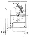
- the mains comprises phase wires L1, L2, L3, neutral wire N and protective, i.e. grounding wire PE.
- Electric block 5 has been connected to phase wire L1 over a fuse 6 or similar.
- Electric block 5 includes ligth fittings 8, their light switch 8a and a number of sockets 9. The safety arrangement in accordance with the invention has been connected to electric block 5.
- the safety arrangement of the invention comprises a smoke detector, such as a fire alarm 1, a relay unit 2 and a fault current safety switch 7.
- Fire alarm 1 is protected with an accumulator or a battery and is supplied with mains current, and it can be directly connected to relay unit 2.
- Fire alarm 1 and relay unit 2 are mutually connected with the real delivery of current wire L, neutral wire Np and impulse wire I.
- Relay unit 2 comprises a relay coil 3 and the relay switch 4 proper, which comprises the central terminal 4c of the switch 4 and optional contact terminals 4a, 4b.
- the central terminal 4c of the relay switch 4 and the second optional terminal 4b have been connected to the neutral wire N sr and to the grounding wire PE accordingly.
- the first optional terminal 4a of the relay switch 4 is free; it has not been connected at all.
- Fire alarm 1 and relay unit 2 have been connected to the same electric block 5 and are thus protected by one fuse 6.
- the fault current safety switch 7 included in the safety arrangement is connected between fuse 6 and electric block 5 such that the supply voltage of the mains passes from phase wire L1 to electric block 5 over terminals 7a, 7b with the neutral wire N outside electric block 5 connected to neutral wire N sr of electric block 5 over terminals 7c, 7d.
- the battery-protected fire alarm 1 may be of any type known per se, as for instance a ionisation-based, mains voltage-operated smoke detector equipped with accumulator protection marketed under the trade name BRK-Electronics Model 86 E.
- Relay unit 2 may accordingly be a relay unit equipped with an amplifier manufactured by the same manufacturer for this fire alarm 1.
- Several fire alarms, such as a maximun of 12 units, may be advantageously connected to one relay unit.
- the fault current safety switch 7 is as such a safety interruptor known per se.
- the fault current safety switch 7 operates according to the sum current principle. In a normal situation, the sum current of phase wire L1 and neutral wire N sr is zero. In fault situations, the sum current is different from zero.
- the fault current will return to the ground e.g. over grounding wire PE. This results in current imbalance. If the fault current exceeds a predetermined excitation current value of the fault current safety switch 7, the fault current safety switch 7 will be immediately actuated, interrupting the delivery of current from the phase wire L1 to electric block 5.
- fault current safety switch 7 can be used to control another switch to interrupt the delivery of current to electric block 5.
- fault current safety switch 7 can be a "separate fault current block", which can then be used to control a high-power switch from the same device manufacturer to interrupt the delivery of current to the monitored part of the mains.
- the excitation current value of the fault current safety switch 7 is e.g. 30 mA.
- the safety arrangement operates as follows.
- fire alarm 1 detects for instance smoke in a room, it sends an impulse to relay unit 2 and especially to relay control coil 3.
- switch 4 In operating position B switch 4 is closed, i.e. terminals 4c, 4b are interconnected, and then neutral wire N sr and grounding wire PE are interconnected.
- In rest position A switch 4 In rest position A switch 4 is open and neutral wire N sr and grounding wire PE are not electrically connected to each other. It should be noted that neither of said wires N sr and PE have any significant potential difference compared to the grounding of the electric system.
- relay unit 2 will not cause any short-circuiting voltage or current peak in electric block 5, and such a peak, even at a minimum, would release or blow fuse 6 protecting the electric block.
- Switching switch 4 into operating position B results in neutral wire N and grounding wire PE being interconnected, and on the basis of the conductor resistors of these, part (usually 50%) of the return current of the electric block is directed to grounding wire PE. If this part of the return current exceeds the excitation current of the fault current safety switch 7, e.g. 30 mA, the fault current safety switch 7 will operate, interrupting the delivery of current to electric block 5.
- the delivery of current to this device will be interrupted, In this way, the electric device will be disconnected from the mains as soon as the fire starts, and thus the entire fire will most likely subdue from the very beginning.
- fire alarm 1 is equipped with a reserve power source of its own, such as an accumulator, and then the fire alarm goes on operating, warning about a dangerous situation with an alarm signal also after the mains voltage has been interrupted.
- a reserve power source of its own such as an accumulator
- the fault current safety switch 7 requires a small base load, which is typically e.g. 60 mA with a mains voltage of 230 VAC (such as the voltage of phase conductor L1). Expressed as electric power this base load is about 15 W, electric loads in this power class being among other things incandescence, i.e. readiness for working, of the picture tube in a television set A continuously prevailing base load can be ensured by providing electric block 5, such as the switch box or instrument case of the room to be protected, with a firmly connected resistor 10. This resistor 10 may for instance be a 15 W heating resistor, which can be performed by means of a self-adjusting heating cable. On the other hand, if no electric load is in operation, there will be no need for the safety arrangement to be actuated.
- the fault current safety switch 7 of the safety arrangement which is preferably a switch fastened with a DIN rail, can be retrofitted in a mounting casing disposed in the block distribution board or in its immediate vicinity.
- a mounting casing is principally used in connection with fuse block boards.
- new electric installations do not require additional cabling or wiring between the room protected with a fire alarm and the block distribution board supplying it.
- an additional grounding wire shall principally be added between the delivery of current wire L1 or dip wires of the room to be protected and the supplying block distribution board.
- Fire alarm 1 can be correctly disposed in the room to be protected from a fire-technical point of view, and new cabling will be required only from the fire alarm to the mains switch box closest to the room to be protected.
Landscapes
- Power Engineering (AREA)
- Engineering & Computer Science (AREA)
- Fire Alarms (AREA)
- Burglar Alarm Systems (AREA)
- Alarm Systems (AREA)
- Power Sources (AREA)
- Stand-By Power Supply Arrangements (AREA)
- Electrophonic Musical Instruments (AREA)
- Transmitters (AREA)
- Apparatus For Radiation Diagnosis (AREA)
- Electrical Discharge Machining, Electrochemical Machining, And Combined Machining (AREA)
- Golf Clubs (AREA)
- Earth Drilling (AREA)
- Preparation Of Compounds By Using Micro-Organisms (AREA)
- Direct Current Feeding And Distribution (AREA)
- Emergency Protection Circuit Devices (AREA)
- Fire-Detection Mechanisms (AREA)
- Cable Accessories (AREA)
- Details Of Connecting Devices For Male And Female Coupling (AREA)
Claims (5)
- Procédé pour interrompre l'alimentation en courant d'un réseau électrique dans une situation dangereuse, utilisant au moins un détecteur de fumée, tel qu'un avertisseur d'incendie (1) ou un détecteur d'environnement similaire pour délivrer un message, tel qu'une impulsion, lorsque les conditions environnantes changent et dépassent des limites prédéfinies, et une unité de relais (2) ou un commutateur similaire relié à cela, qui est mis en état conducteur par un message du détecteur de fumée, caractérisé en ce que l'unité de relais (2) sert à relier électriquement le fil de terre (PE) et le fil neutre (Nsr) du réseau électrique, et ensuite une partie du courant réfléchi est dirigé sur la base des résistances de conducteur de ces fils vers le fil de terre (PE), puis, dans une situation normale, un déséquilibre se produira dans le courant de somme zéro entre le fil de phase (L1) et le fil neutre (Nsr), cette valeur de courant de somme différente de zéro dépassant une valeur limite prédéfinie, qui est détectée et entraíne l'interruption de l'alimentation de courant.
- Procédé selon la revendication 1, caractérisé en ce que le courant de défaut est contrôlé dans le bloc électrique (5) déterminé par le fusible (6) général auquel l'avertisseur d'incendie (1) a aussi été relié, l'alimentation de courant de la partie secteur (5) protégée par ce fusible (6) étant interrompue dans une situation de risque.
- Dispositif de sécurité pour interrompre l'alimentation en courant du secteur dans une situation dangereuse, comprenant un interrupteur de sécurité à courant de défaut 7, au moins un détecteur de fumée, tel qu'un avertisseur d'incendie (1) ou un détecteur d'environnement similaire pour donner un message, comme une impulsion, lorsque les conditions environnantes changent et dépassent des limites prédéfinies, et une unité de relais (2) ou une unité de commutation similaire reliée à cela, comprenant un commutateur à relais (4) ou un commutateur similaire, qui est mis à l'état conducteur, c'est-à-dire en position de fonctionnement (B) par un message de l'avertisseur d'incendie (1), caractérisé en ce que le commutateur à relais (4) compris dans l'unité de relais (2) a été disposé entre le fil neutre (Nsr) et le fil de terre (PE) du réseau électrique, le commutateur à relais (4) une fois mis à l'état conducteur, c.-à-d. en position de fonctionnement (B) fait qu'une partie du courant réfléchi est dirigée sur la base des résistances de conducteur vers le fil de terre (PE), et dans une situation normale, il y aura ensuite un déséquilibre dans le courant de somme zéro du fil de phase (L1) et du fil neutre (Nsr) et lorsque cette valeur de courant de somme différente de zéro dépasse la valeur du courant d'excitation de l'interrupteur de sécurité à courant de défaut (7), l'interrupteur de sécurité à courant de défaut (7) est actionné, interrompant l'alimentation en courant.
- Dispositif de sécurité selon la revendication 3, caractérisé en ce que l'interrupteur de sécurité à courant de défaut (7) a été disposé en relation avec le fusible secteur (6) déterminant le bloc électrique (5) auquel l'avertisseur d'incendie (1) a aussi été relié, l'alimentation en courant étant interrompue à la partie secteur protégée par ce fusible (6) dans une situation de risque.
- Dispositif de sécurité selon la revendication 4, caractérisé en ce que, de manière à maintenir l'aptitude de fonctionnement continue de l'interrupteur de sécurité à courant de défaut (7), une résistance (10) a été de préférence fermement reliée au bloc électrique (5).
Applications Claiming Priority (3)
| Application Number | Priority Date | Filing Date | Title |
|---|---|---|---|
| FI980789A FI105861B (fi) | 1998-04-06 | 1998-04-06 | Menetelmä verkon sähkönsyötön katkaisemiseksi vaaratilanteessa ja vastaava turvajärjestely |
| FI980789 | 1998-04-06 | ||
| PCT/FI1999/000287 WO1999052090A1 (fr) | 1998-04-06 | 1999-04-06 | Procede d'interruption de l'alimentation electrique en cas de danger, et systeme de securite associe |
Publications (2)
| Publication Number | Publication Date |
|---|---|
| EP1068601A1 EP1068601A1 (fr) | 2001-01-17 |
| EP1068601B1 true EP1068601B1 (fr) | 2003-07-30 |
Family
ID=8551477
Family Applications (1)
| Application Number | Title | Priority Date | Filing Date |
|---|---|---|---|
| EP99913349A Expired - Lifetime EP1068601B1 (fr) | 1998-04-06 | 1999-04-06 | Procede d'interruption de l'alimentation electrique en cas de danger, et systeme de securite associe |
Country Status (14)
| Country | Link |
|---|---|
| EP (1) | EP1068601B1 (fr) |
| JP (1) | JP4185666B2 (fr) |
| CN (1) | CN1133966C (fr) |
| AT (1) | ATE246386T1 (fr) |
| AU (1) | AU759258B2 (fr) |
| CA (1) | CA2327296A1 (fr) |
| DE (1) | DE69909991T2 (fr) |
| DK (1) | DK1068601T3 (fr) |
| ES (1) | ES2205796T3 (fr) |
| FI (1) | FI105861B (fr) |
| NO (1) | NO324480B1 (fr) |
| PL (1) | PL191284B1 (fr) |
| PT (1) | PT1068601E (fr) |
| WO (1) | WO1999052090A1 (fr) |
Cited By (1)
| Publication number | Priority date | Publication date | Assignee | Title |
|---|---|---|---|---|
| WO2009040554A2 (fr) * | 2007-09-28 | 2009-04-02 | Graham Chilvers | Appareil de commande d'alimentation |
Families Citing this family (15)
| Publication number | Priority date | Publication date | Assignee | Title |
|---|---|---|---|---|
| FI116550B (fi) | 2004-01-29 | 2005-12-15 | Abb Oy | Ympäristösulake |
| CN100366988C (zh) * | 2004-03-24 | 2008-02-06 | 谭启仁 | 强排式燃气热水器全方位人身安全保护装置 |
| GB2438252A (en) * | 2005-10-01 | 2007-11-21 | Philip Marson | Fire alarm isolates power circuits |
| FI20065263A (fi) * | 2006-04-25 | 2007-10-26 | Innohome Oy | Järjestelmä sähkön-, veden- tai kaasunsyötön ohjaamiseksi |
| GB2477737A (en) * | 2010-02-10 | 2011-08-17 | Michael James Newman | Fire prevention system triggering a residual current device |
| GB2477954A (en) * | 2010-02-19 | 2011-08-24 | Haven Ltd | Explosive gas detection unit and electrical fitting including such a unit |
| DE102010054386B3 (de) * | 2010-12-06 | 2012-02-23 | Pilz Gmbh. & Co. Kg | Sicherheitsschaltgerät zum fehlersicheren Abschalten eines elektrischen Verbrauchers |
| CN102931645B (zh) * | 2011-08-09 | 2016-03-30 | 珠海格力电器股份有限公司 | 地线带电保护电路、方法及具有该电路的空调器 |
| ES2389360B2 (es) * | 2012-05-18 | 2014-07-30 | Universidad De La Rioja | Sistema de detección de vida útil de lámparas de descarga |
| CN103050939A (zh) * | 2012-12-26 | 2013-04-17 | 青岛盛嘉信息科技有限公司 | 火灾断电保护电路 |
| ES1078439Y (es) * | 2012-12-28 | 2013-04-22 | Guiu Eduard Josep Jordi Bages | Dispositivo de seguridad por deteccion de gases |
| CN104518478B (zh) * | 2013-09-30 | 2017-08-25 | 哈尔滨飞机工业集团有限责任公司 | 一种飞机电源系统的卸载装置 |
| CN105246219A (zh) * | 2015-11-11 | 2016-01-13 | 江苏银佳企业集团有限公司 | 一种火灾应急照明管理系统 |
| CN109788604A (zh) * | 2017-12-22 | 2019-05-21 | 湖南汇博电子科技股份有限公司 | 消防信息控制方法、装置、系统和存储介质 |
| CN108695820A (zh) * | 2018-07-21 | 2018-10-23 | 朱德锋 | 防逆电接地保护系统 |
Family Cites Families (3)
| Publication number | Priority date | Publication date | Assignee | Title |
|---|---|---|---|---|
| FR2543839B1 (fr) * | 1983-04-08 | 1986-04-18 | Pgep | Dispositif autonome de protection d'un ensemble electrique contre l'incendie |
| DE3636502A1 (de) * | 1986-10-27 | 1988-04-28 | Gaertner Paul Dipl Kaufm | Schutzvorrichtung gegen gasexplosionen in wohnraeumen |
| FR2643195B1 (fr) * | 1989-02-15 | 1992-12-31 | Univ Alsace | Procede et dispositif de protection d'un circuit ou reseau electrique a l'aide d'un disjoncteur a courant differentiel |
-
1998
- 1998-04-06 FI FI980789A patent/FI105861B/fi not_active IP Right Cessation
-
1999
- 1999-04-06 DE DE69909991T patent/DE69909991T2/de not_active Expired - Lifetime
- 1999-04-06 EP EP99913349A patent/EP1068601B1/fr not_active Expired - Lifetime
- 1999-04-06 PT PT99913349T patent/PT1068601E/pt unknown
- 1999-04-06 ES ES99913349T patent/ES2205796T3/es not_active Expired - Lifetime
- 1999-04-06 WO PCT/FI1999/000287 patent/WO1999052090A1/fr active IP Right Grant
- 1999-04-06 PL PL343351A patent/PL191284B1/pl not_active IP Right Cessation
- 1999-04-06 CN CNB998046396A patent/CN1133966C/zh not_active Expired - Fee Related
- 1999-04-06 CA CA002327296A patent/CA2327296A1/fr not_active Abandoned
- 1999-04-06 AU AU31509/99A patent/AU759258B2/en not_active Ceased
- 1999-04-06 DK DK99913349T patent/DK1068601T3/da active
- 1999-04-06 AT AT99913349T patent/ATE246386T1/de not_active IP Right Cessation
- 1999-04-06 JP JP2000542756A patent/JP4185666B2/ja not_active Expired - Fee Related
-
2000
- 2000-10-05 NO NO20005024A patent/NO324480B1/no not_active IP Right Cessation
Cited By (4)
| Publication number | Priority date | Publication date | Assignee | Title |
|---|---|---|---|---|
| WO2009040554A2 (fr) * | 2007-09-28 | 2009-04-02 | Graham Chilvers | Appareil de commande d'alimentation |
| WO2009040554A3 (fr) * | 2007-09-28 | 2009-05-14 | Graham Chilvers | Appareil de commande d'alimentation |
| GB2457639A (en) * | 2007-09-28 | 2009-08-26 | Graham Chilvers | Power control apparatus |
| GB2457639B (en) * | 2007-09-28 | 2010-08-18 | Graham Chilvers | Power control apparatus |
Also Published As
| Publication number | Publication date |
|---|---|
| NO20005024L (no) | 2000-12-04 |
| PL191284B1 (pl) | 2006-04-28 |
| PT1068601E (pt) | 2003-12-31 |
| ATE246386T1 (de) | 2003-08-15 |
| AU3150999A (en) | 1999-10-25 |
| NO20005024D0 (no) | 2000-10-05 |
| PL343351A1 (en) | 2001-08-13 |
| DE69909991T2 (de) | 2004-05-19 |
| NO324480B1 (no) | 2007-10-29 |
| AU759258B2 (en) | 2003-04-10 |
| ES2205796T3 (es) | 2004-05-01 |
| CA2327296A1 (fr) | 1999-10-14 |
| JP4185666B2 (ja) | 2008-11-26 |
| DE69909991D1 (de) | 2003-09-04 |
| JP2002532769A (ja) | 2002-10-02 |
| FI980789A (fi) | 1999-10-07 |
| WO1999052090A1 (fr) | 1999-10-14 |
| CN1295700A (zh) | 2001-05-16 |
| CN1133966C (zh) | 2004-01-07 |
| EP1068601A1 (fr) | 2001-01-17 |
| DK1068601T3 (da) | 2003-11-10 |
| FI980789A0 (fi) | 1998-04-06 |
| FI105861B (fi) | 2000-10-13 |
Similar Documents
| Publication | Publication Date | Title |
|---|---|---|
| EP1068601B1 (fr) | Procede d'interruption de l'alimentation electrique en cas de danger, et systeme de securite associe | |
| US5510946A (en) | Circuit breaker protection against "arc short circuit" hazards | |
| US6456471B1 (en) | Test, reset and communications operations in an ARC fault circuit interrupter with optional memory and/or backup power | |
| AU5600899A (en) | Power distribution system with circuit breakers remotely resettable by signals transmitted over the power lines | |
| US20070258175A1 (en) | Method and apparatus for open neutral fault detection | |
| KR101799954B1 (ko) | 과열로 인한 사고 확산의 방지 기능을 갖는 배전반 | |
| US8084890B2 (en) | Apparatus and method for fire protection of electrical installations | |
| WO1996042131A1 (fr) | Systeme de cablage electrique a protection contre les temperatures excessives | |
| RU2737951C1 (ru) | Комплекс контроля и защиты электроустановки | |
| AU2005313826B2 (en) | Master breaker device for back-up protection against electric shock in earthed user units with mains voltage dependent residual current triggering and high selectivity | |
| AU2018101001A4 (en) | Apparatus, system and method for alarm triggered electrical supply disconnection | |
| GB2477737A (en) | Fire prevention system triggering a residual current device | |
| US6621677B1 (en) | Method and system for series fault protection | |
| CA2587965A1 (fr) | Methode et appareil pour detection d'un defaut de coupure du conducteur de neutre | |
| RU2689876C1 (ru) | Модульная вентиляционная система | |
| KR20080105496A (ko) | 콘센트 | |
| WO2015080569A1 (fr) | Procédé de détection automatique de défaillance d'énergie permettant de surveiller et de commander un système de distribution d'énergie | |
| WO2002082484A1 (fr) | Procede de surveillance des contacts | |
| KR200208928Y1 (ko) | 전기 누전 경보장치 | |
| Eaton | Electric services and building fires | |
| Koustellis et al. | PROTECTIVE MEASURES AGAINST ELECTRICAL HAZARDS OF CONSUMER INSTALLATIONS | |
| Kidd | Electrical protection for domestic and small commercial installations | |
| JPH09163524A (ja) | 非常時電源遮断装置付分電盤 | |
| GB2539164A (en) | Protective master switch |
Legal Events
| Date | Code | Title | Description |
|---|---|---|---|
| PUAI | Public reference made under article 153(3) epc to a published international application that has entered the european phase |
Free format text: ORIGINAL CODE: 0009012 |
|
| 17P | Request for examination filed |
Effective date: 20001102 |
|
| AK | Designated contracting states |
Kind code of ref document: A1 Designated state(s): AT BE CH DE DK ES FR GB GR IE IT LI NL PT SE |
|
| GRAH | Despatch of communication of intention to grant a patent |
Free format text: ORIGINAL CODE: EPIDOS IGRA |
|
| GRAH | Despatch of communication of intention to grant a patent |
Free format text: ORIGINAL CODE: EPIDOS IGRA |
|
| GRAA | (expected) grant |
Free format text: ORIGINAL CODE: 0009210 |
|
| AK | Designated contracting states |
Designated state(s): AT BE CH DE DK ES FR GB GR IE IT LI NL PT SE |
|
| REG | Reference to a national code |
Ref country code: GB Ref legal event code: FG4D |
|
| REG | Reference to a national code |
Ref country code: CH Ref legal event code: EP |
|
| REG | Reference to a national code |
Ref country code: IE Ref legal event code: FG4D |
|
| REF | Corresponds to: |
Ref document number: 69909991 Country of ref document: DE Date of ref document: 20030904 Kind code of ref document: P |
|
| REG | Reference to a national code |
Ref country code: SE Ref legal event code: TRGR |
|
| REG | Reference to a national code |
Ref country code: CH Ref legal event code: NV Representative=s name: E. BLUM & CO. PATENTANWAELTE |
|
| REG | Reference to a national code |
Ref country code: DK Ref legal event code: T3 |
|
| REG | Reference to a national code |
Ref country code: GR Ref legal event code: EP Ref document number: 20030404136 Country of ref document: GR |
|
| REG | Reference to a national code |
Ref country code: ES Ref legal event code: FG2A Ref document number: 2205796 Country of ref document: ES Kind code of ref document: T3 |
|
| ET | Fr: translation filed | ||
| PLBE | No opposition filed within time limit |
Free format text: ORIGINAL CODE: 0009261 |
|
| STAA | Information on the status of an ep patent application or granted ep patent |
Free format text: STATUS: NO OPPOSITION FILED WITHIN TIME LIMIT |
|
| 26N | No opposition filed |
Effective date: 20040504 |
|
| REG | Reference to a national code |
Ref country code: CH Ref legal event code: PFA Owner name: KAARNAMO, ANTTI Free format text: KAARNAMO, ANTTI#LAHELANTIE 184#04330 LAHELA (FI) -TRANSFER TO- KAARNAMO, ANTTI#LAHELANTIE 184#04330 LAHELA (FI) |
|
| PGFP | Annual fee paid to national office [announced via postgrant information from national office to epo] |
Ref country code: PT Payment date: 20100326 Year of fee payment: 12 |
|
| PGFP | Annual fee paid to national office [announced via postgrant information from national office to epo] |
Ref country code: IE Payment date: 20100426 Year of fee payment: 12 Ref country code: FR Payment date: 20100521 Year of fee payment: 12 Ref country code: ES Payment date: 20100420 Year of fee payment: 12 |
|
| PGFP | Annual fee paid to national office [announced via postgrant information from national office to epo] |
Ref country code: NL Payment date: 20100426 Year of fee payment: 12 Ref country code: IT Payment date: 20100426 Year of fee payment: 12 Ref country code: AT Payment date: 20100428 Year of fee payment: 12 |
|
| PGFP | Annual fee paid to national office [announced via postgrant information from national office to epo] |
Ref country code: CH Payment date: 20100414 Year of fee payment: 12 Ref country code: BE Payment date: 20100426 Year of fee payment: 12 |
|
| PGFP | Annual fee paid to national office [announced via postgrant information from national office to epo] |
Ref country code: GR Payment date: 20100331 Year of fee payment: 12 |
|
| REG | Reference to a national code |
Ref country code: PT Ref legal event code: MM4A Free format text: LAPSE DUE TO NON-PAYMENT OF FEES Effective date: 20111006 |
|
| BERE | Be: lapsed |
Owner name: *KAARNAMO ANTTI Effective date: 20110430 |
|
| REG | Reference to a national code |
Ref country code: NL Ref legal event code: V1 Effective date: 20111101 |
|
| REG | Reference to a national code |
Ref country code: CH Ref legal event code: PL |
|
| REG | Reference to a national code |
Ref country code: AT Ref legal event code: MM01 Ref document number: 246386 Country of ref document: AT Kind code of ref document: T Effective date: 20110406 |
|
| REG | Reference to a national code |
Ref country code: GR Ref legal event code: ML Ref document number: 20030404136 Country of ref document: GR Effective date: 20111102 |
|
| REG | Reference to a national code |
Ref country code: FR Ref legal event code: ST Effective date: 20111230 |
|
| PG25 | Lapsed in a contracting state [announced via postgrant information from national office to epo] |
Ref country code: LI Free format text: LAPSE BECAUSE OF NON-PAYMENT OF DUE FEES Effective date: 20110430 Ref country code: CH Free format text: LAPSE BECAUSE OF NON-PAYMENT OF DUE FEES Effective date: 20110430 Ref country code: BE Free format text: LAPSE BECAUSE OF NON-PAYMENT OF DUE FEES Effective date: 20110430 Ref country code: NL Free format text: LAPSE BECAUSE OF NON-PAYMENT OF DUE FEES Effective date: 20111101 Ref country code: FR Free format text: LAPSE BECAUSE OF NON-PAYMENT OF DUE FEES Effective date: 20110502 Ref country code: PT Free format text: LAPSE BECAUSE OF NON-PAYMENT OF DUE FEES Effective date: 20111006 |
|
| REG | Reference to a national code |
Ref country code: IE Ref legal event code: MM4A |
|
| PG25 | Lapsed in a contracting state [announced via postgrant information from national office to epo] |
Ref country code: IT Free format text: LAPSE BECAUSE OF NON-PAYMENT OF DUE FEES Effective date: 20110406 Ref country code: AT Free format text: LAPSE BECAUSE OF NON-PAYMENT OF DUE FEES Effective date: 20110406 Ref country code: GR Free format text: LAPSE BECAUSE OF NON-PAYMENT OF DUE FEES Effective date: 20111102 |
|
| PG25 | Lapsed in a contracting state [announced via postgrant information from national office to epo] |
Ref country code: IE Free format text: LAPSE BECAUSE OF NON-PAYMENT OF DUE FEES Effective date: 20110406 |
|
| REG | Reference to a national code |
Ref country code: ES Ref legal event code: FD2A Effective date: 20120524 |
|
| PG25 | Lapsed in a contracting state [announced via postgrant information from national office to epo] |
Ref country code: ES Free format text: LAPSE BECAUSE OF NON-PAYMENT OF DUE FEES Effective date: 20110407 |
|
| PGFP | Annual fee paid to national office [announced via postgrant information from national office to epo] |
Ref country code: GB Payment date: 20140423 Year of fee payment: 16 |
|
| PGFP | Annual fee paid to national office [announced via postgrant information from national office to epo] |
Ref country code: DE Payment date: 20140422 Year of fee payment: 16 |
|
| PGFP | Annual fee paid to national office [announced via postgrant information from national office to epo] |
Ref country code: DK Payment date: 20140424 Year of fee payment: 16 |
|
| PGFP | Annual fee paid to national office [announced via postgrant information from national office to epo] |
Ref country code: SE Payment date: 20150423 Year of fee payment: 17 |
|
| REG | Reference to a national code |
Ref country code: DE Ref legal event code: R119 Ref document number: 69909991 Country of ref document: DE |
|
| REG | Reference to a national code |
Ref country code: DK Ref legal event code: EBP Effective date: 20150430 |
|
| GBPC | Gb: european patent ceased through non-payment of renewal fee |
Effective date: 20150406 |
|
| PG25 | Lapsed in a contracting state [announced via postgrant information from national office to epo] |
Ref country code: GB Free format text: LAPSE BECAUSE OF NON-PAYMENT OF DUE FEES Effective date: 20150406 Ref country code: DE Free format text: LAPSE BECAUSE OF NON-PAYMENT OF DUE FEES Effective date: 20151103 |
|
| PG25 | Lapsed in a contracting state [announced via postgrant information from national office to epo] |
Ref country code: DK Free format text: LAPSE BECAUSE OF NON-PAYMENT OF DUE FEES Effective date: 20150430 |
|
| REG | Reference to a national code |
Ref country code: SE Ref legal event code: EUG |
|
| PG25 | Lapsed in a contracting state [announced via postgrant information from national office to epo] |
Ref country code: SE Free format text: LAPSE BECAUSE OF NON-PAYMENT OF DUE FEES Effective date: 20160407 |