EP1068161B1 - Use of high temperature insulation for ceramic matrix composites in gas turbines - Google Patents
Use of high temperature insulation for ceramic matrix composites in gas turbines Download PDFInfo
- Publication number
- EP1068161B1 EP1068161B1 EP99910952A EP99910952A EP1068161B1 EP 1068161 B1 EP1068161 B1 EP 1068161B1 EP 99910952 A EP99910952 A EP 99910952A EP 99910952 A EP99910952 A EP 99910952A EP 1068161 B1 EP1068161 B1 EP 1068161B1
- Authority
- EP
- European Patent Office
- Prior art keywords
- spheres
- composition
- coating
- turbine
- gas turbine
- Prior art date
- Legal status (The legal status is an assumption and is not a legal conclusion. Google has not performed a legal analysis and makes no representation as to the accuracy of the status listed.)
- Expired - Lifetime
Links
- 239000011153 ceramic matrix composite Substances 0.000 title claims description 17
- 238000009413 insulation Methods 0.000 title description 11
- 239000000203 mixture Substances 0.000 claims description 43
- 239000007789 gas Substances 0.000 claims description 37
- 239000000945 filler Substances 0.000 claims description 21
- 239000000843 powder Substances 0.000 claims description 19
- 239000000919 ceramic Substances 0.000 claims description 18
- 239000000758 substrate Substances 0.000 claims description 18
- 230000007704 transition Effects 0.000 claims description 18
- 239000002694 phosphate binding agent Substances 0.000 claims description 15
- 238000000576 coating method Methods 0.000 description 68
- 239000011248 coating agent Substances 0.000 description 62
- 239000000463 material Substances 0.000 description 28
- 238000001816 cooling Methods 0.000 description 26
- 238000002485 combustion reaction Methods 0.000 description 22
- KZHJGOXRZJKJNY-UHFFFAOYSA-N dioxosilane;oxo(oxoalumanyloxy)alumane Chemical compound O=[Si]=O.O=[Si]=O.O=[Al]O[Al]=O.O=[Al]O[Al]=O.O=[Al]O[Al]=O KZHJGOXRZJKJNY-UHFFFAOYSA-N 0.000 description 19
- 229910052863 mullite Inorganic materials 0.000 description 19
- PNEYBMLMFCGWSK-UHFFFAOYSA-N aluminium oxide Inorganic materials [O-2].[O-2].[O-2].[Al+3].[Al+3] PNEYBMLMFCGWSK-UHFFFAOYSA-N 0.000 description 14
- 238000010304 firing Methods 0.000 description 13
- 239000002131 composite material Substances 0.000 description 12
- 239000012720 thermal barrier coating Substances 0.000 description 11
- 230000003628 erosive effect Effects 0.000 description 10
- 238000000034 method Methods 0.000 description 9
- ILRRQNADMUWWFW-UHFFFAOYSA-K aluminium phosphate Chemical compound O1[Al]2OP1(=O)O2 ILRRQNADMUWWFW-UHFFFAOYSA-K 0.000 description 8
- 239000000853 adhesive Substances 0.000 description 7
- 230000001070 adhesive effect Effects 0.000 description 7
- 238000005266 casting Methods 0.000 description 7
- 238000001035 drying Methods 0.000 description 7
- 239000002002 slurry Substances 0.000 description 7
- 238000010276 construction Methods 0.000 description 6
- 229910002076 stabilized zirconia Inorganic materials 0.000 description 6
- 229910019142 PO4 Inorganic materials 0.000 description 5
- 229910002091 carbon monoxide Inorganic materials 0.000 description 5
- 239000000446 fuel Substances 0.000 description 5
- 239000011159 matrix material Substances 0.000 description 5
- NBIIXXVUZAFLBC-UHFFFAOYSA-K phosphate Chemical compound [O-]P([O-])([O-])=O NBIIXXVUZAFLBC-UHFFFAOYSA-K 0.000 description 5
- 239000010452 phosphate Substances 0.000 description 5
- XLYOFNOQVPJJNP-UHFFFAOYSA-N water Chemical compound O XLYOFNOQVPJJNP-UHFFFAOYSA-N 0.000 description 5
- VYPSYNLAJGMNEJ-UHFFFAOYSA-N Silicium dioxide Chemical compound O=[Si]=O VYPSYNLAJGMNEJ-UHFFFAOYSA-N 0.000 description 4
- 238000005524 ceramic coating Methods 0.000 description 4
- 230000008859 change Effects 0.000 description 4
- 238000010438 heat treatment Methods 0.000 description 4
- 238000011065 in-situ storage Methods 0.000 description 4
- 230000035882 stress Effects 0.000 description 4
- UGFAIRIUMAVXCW-UHFFFAOYSA-N Carbon monoxide Chemical compound [O+]#[C-] UGFAIRIUMAVXCW-UHFFFAOYSA-N 0.000 description 3
- 229910010293 ceramic material Inorganic materials 0.000 description 3
- 229930195733 hydrocarbon Natural products 0.000 description 3
- 150000002430 hydrocarbons Chemical class 0.000 description 3
- 238000004519 manufacturing process Methods 0.000 description 3
- 230000008569 process Effects 0.000 description 3
- PXHVJJICTQNCMI-UHFFFAOYSA-N Nickel Chemical compound [Ni] PXHVJJICTQNCMI-UHFFFAOYSA-N 0.000 description 2
- 239000007864 aqueous solution Substances 0.000 description 2
- 230000008901 benefit Effects 0.000 description 2
- 239000007795 chemical reaction product Substances 0.000 description 2
- 239000000567 combustion gas Substances 0.000 description 2
- 238000002156 mixing Methods 0.000 description 2
- 230000001590 oxidative effect Effects 0.000 description 2
- 239000002245 particle Substances 0.000 description 2
- 230000002028 premature Effects 0.000 description 2
- 230000009467 reduction Effects 0.000 description 2
- 239000000377 silicon dioxide Substances 0.000 description 2
- 239000000126 substance Substances 0.000 description 2
- 229910000601 superalloy Inorganic materials 0.000 description 2
- 241000588731 Hafnia Species 0.000 description 1
- 229910052581 Si3N4 Inorganic materials 0.000 description 1
- 230000001154 acute effect Effects 0.000 description 1
- 238000005054 agglomeration Methods 0.000 description 1
- 230000002776 aggregation Effects 0.000 description 1
- 229910000323 aluminium silicate Inorganic materials 0.000 description 1
- 230000004323 axial length Effects 0.000 description 1
- 230000004888 barrier function Effects 0.000 description 1
- 239000006227 byproduct Substances 0.000 description 1
- 230000015556 catabolic process Effects 0.000 description 1
- CETPSERCERDGAM-UHFFFAOYSA-N ceric oxide Chemical compound O=[Ce]=O CETPSERCERDGAM-UHFFFAOYSA-N 0.000 description 1
- 229910000422 cerium(IV) oxide Inorganic materials 0.000 description 1
- 238000006243 chemical reaction Methods 0.000 description 1
- 239000000470 constituent Substances 0.000 description 1
- 239000013078 crystal Substances 0.000 description 1
- 230000002950 deficient Effects 0.000 description 1
- 230000018044 dehydration Effects 0.000 description 1
- 238000006297 dehydration reaction Methods 0.000 description 1
- 239000008367 deionised water Substances 0.000 description 1
- 229910021641 deionized water Inorganic materials 0.000 description 1
- 238000010790 dilution Methods 0.000 description 1
- 239000012895 dilution Substances 0.000 description 1
- HNPSIPDUKPIQMN-UHFFFAOYSA-N dioxosilane;oxo(oxoalumanyloxy)alumane Chemical compound O=[Si]=O.O=[Al]O[Al]=O HNPSIPDUKPIQMN-UHFFFAOYSA-N 0.000 description 1
- 238000006073 displacement reaction Methods 0.000 description 1
- 230000005611 electricity Effects 0.000 description 1
- 239000000835 fiber Substances 0.000 description 1
- 239000012530 fluid Substances 0.000 description 1
- 230000004907 flux Effects 0.000 description 1
- 238000009472 formulation Methods 0.000 description 1
- 239000011521 glass Substances 0.000 description 1
- CJNBYAVZURUTKZ-UHFFFAOYSA-N hafnium(IV) oxide Inorganic materials O=[Hf]=O CJNBYAVZURUTKZ-UHFFFAOYSA-N 0.000 description 1
- 238000007731 hot pressing Methods 0.000 description 1
- 230000008595 infiltration Effects 0.000 description 1
- 238000001764 infiltration Methods 0.000 description 1
- 238000009434 installation Methods 0.000 description 1
- 239000012774 insulation material Substances 0.000 description 1
- 239000012212 insulator Substances 0.000 description 1
- 238000000626 liquid-phase infiltration Methods 0.000 description 1
- 238000003754 machining Methods 0.000 description 1
- 230000013011 mating Effects 0.000 description 1
- 238000002844 melting Methods 0.000 description 1
- 230000008018 melting Effects 0.000 description 1
- 239000010814 metallic waste Substances 0.000 description 1
- 239000004005 microsphere Substances 0.000 description 1
- 229910052759 nickel Inorganic materials 0.000 description 1
- 238000005121 nitriding Methods 0.000 description 1
- 238000000643 oven drying Methods 0.000 description 1
- 230000003647 oxidation Effects 0.000 description 1
- 238000007254 oxidation reaction Methods 0.000 description 1
- 125000002467 phosphate group Chemical group [H]OP(=O)(O[H])O[*] 0.000 description 1
- 238000010248 power generation Methods 0.000 description 1
- 238000002360 preparation method Methods 0.000 description 1
- 238000001272 pressureless sintering Methods 0.000 description 1
- 238000010791 quenching Methods 0.000 description 1
- 230000000171 quenching effect Effects 0.000 description 1
- 239000002994 raw material Substances 0.000 description 1
- 230000008439 repair process Effects 0.000 description 1
- 239000000565 sealant Substances 0.000 description 1
- 238000007789 sealing Methods 0.000 description 1
- 238000007493 shaping process Methods 0.000 description 1
- HBMJWWWQQXIZIP-UHFFFAOYSA-N silicon carbide Chemical compound [Si+]#[C-] HBMJWWWQQXIZIP-UHFFFAOYSA-N 0.000 description 1
- 229910010271 silicon carbide Inorganic materials 0.000 description 1
- HQVNEWCFYHHQES-UHFFFAOYSA-N silicon nitride Chemical compound N12[Si]34N5[Si]62N3[Si]51N64 HQVNEWCFYHHQES-UHFFFAOYSA-N 0.000 description 1
- 238000004901 spalling Methods 0.000 description 1
- 230000008646 thermal stress Effects 0.000 description 1
- 238000011282 treatment Methods 0.000 description 1
- 238000005406 washing Methods 0.000 description 1
- 229910001233 yttria-stabilized zirconia Inorganic materials 0.000 description 1
Images
Classifications
-
- F—MECHANICAL ENGINEERING; LIGHTING; HEATING; WEAPONS; BLASTING
- F01—MACHINES OR ENGINES IN GENERAL; ENGINE PLANTS IN GENERAL; STEAM ENGINES
- F01D—NON-POSITIVE DISPLACEMENT MACHINES OR ENGINES, e.g. STEAM TURBINES
- F01D11/00—Preventing or minimising internal leakage of working-fluid, e.g. between stages
- F01D11/08—Preventing or minimising internal leakage of working-fluid, e.g. between stages for sealing space between rotor blade tips and stator
- F01D11/12—Preventing or minimising internal leakage of working-fluid, e.g. between stages for sealing space between rotor blade tips and stator using a rubstrip, e.g. erodible. deformable or resiliently-biased part
-
- C—CHEMISTRY; METALLURGY
- C04—CEMENTS; CONCRETE; ARTIFICIAL STONE; CERAMICS; REFRACTORIES
- C04B—LIME, MAGNESIA; SLAG; CEMENTS; COMPOSITIONS THEREOF, e.g. MORTARS, CONCRETE OR LIKE BUILDING MATERIALS; ARTIFICIAL STONE; CERAMICS; REFRACTORIES; TREATMENT OF NATURAL STONE
- C04B28/00—Compositions of mortars, concrete or artificial stone, containing inorganic binders or the reaction product of an inorganic and an organic binder, e.g. polycarboxylate cements
- C04B28/34—Compositions of mortars, concrete or artificial stone, containing inorganic binders or the reaction product of an inorganic and an organic binder, e.g. polycarboxylate cements containing cold phosphate binders
- C04B28/344—Compositions of mortars, concrete or artificial stone, containing inorganic binders or the reaction product of an inorganic and an organic binder, e.g. polycarboxylate cements containing cold phosphate binders the phosphate binder being present in the starting composition solely as one or more phosphates
-
- C—CHEMISTRY; METALLURGY
- C04—CEMENTS; CONCRETE; ARTIFICIAL STONE; CERAMICS; REFRACTORIES
- C04B—LIME, MAGNESIA; SLAG; CEMENTS; COMPOSITIONS THEREOF, e.g. MORTARS, CONCRETE OR LIKE BUILDING MATERIALS; ARTIFICIAL STONE; CERAMICS; REFRACTORIES; TREATMENT OF NATURAL STONE
- C04B38/00—Porous mortars, concrete, artificial stone or ceramic ware; Preparation thereof
- C04B38/08—Porous mortars, concrete, artificial stone or ceramic ware; Preparation thereof by adding porous substances
-
- C—CHEMISTRY; METALLURGY
- C04—CEMENTS; CONCRETE; ARTIFICIAL STONE; CERAMICS; REFRACTORIES
- C04B—LIME, MAGNESIA; SLAG; CEMENTS; COMPOSITIONS THEREOF, e.g. MORTARS, CONCRETE OR LIKE BUILDING MATERIALS; ARTIFICIAL STONE; CERAMICS; REFRACTORIES; TREATMENT OF NATURAL STONE
- C04B2111/00—Mortars, concrete or artificial stone or mixtures to prepare them, characterised by specific function, property or use
- C04B2111/00474—Uses not provided for elsewhere in C04B2111/00
- C04B2111/00482—Coating or impregnation materials
-
- C—CHEMISTRY; METALLURGY
- C04—CEMENTS; CONCRETE; ARTIFICIAL STONE; CERAMICS; REFRACTORIES
- C04B—LIME, MAGNESIA; SLAG; CEMENTS; COMPOSITIONS THEREOF, e.g. MORTARS, CONCRETE OR LIKE BUILDING MATERIALS; ARTIFICIAL STONE; CERAMICS; REFRACTORIES; TREATMENT OF NATURAL STONE
- C04B2111/00—Mortars, concrete or artificial stone or mixtures to prepare them, characterised by specific function, property or use
- C04B2111/20—Resistance against chemical, physical or biological attack
- C04B2111/28—Fire resistance, i.e. materials resistant to accidental fires or high temperatures
-
- Y—GENERAL TAGGING OF NEW TECHNOLOGICAL DEVELOPMENTS; GENERAL TAGGING OF CROSS-SECTIONAL TECHNOLOGIES SPANNING OVER SEVERAL SECTIONS OF THE IPC; TECHNICAL SUBJECTS COVERED BY FORMER USPC CROSS-REFERENCE ART COLLECTIONS [XRACs] AND DIGESTS
- Y02—TECHNOLOGIES OR APPLICATIONS FOR MITIGATION OR ADAPTATION AGAINST CLIMATE CHANGE
- Y02T—CLIMATE CHANGE MITIGATION TECHNOLOGIES RELATED TO TRANSPORTATION
- Y02T50/00—Aeronautics or air transport
- Y02T50/60—Efficient propulsion technologies, e.g. for aircraft
-
- Y—GENERAL TAGGING OF NEW TECHNOLOGICAL DEVELOPMENTS; GENERAL TAGGING OF CROSS-SECTIONAL TECHNOLOGIES SPANNING OVER SEVERAL SECTIONS OF THE IPC; TECHNICAL SUBJECTS COVERED BY FORMER USPC CROSS-REFERENCE ART COLLECTIONS [XRACs] AND DIGESTS
- Y10—TECHNICAL SUBJECTS COVERED BY FORMER USPC
- Y10T—TECHNICAL SUBJECTS COVERED BY FORMER US CLASSIFICATION
- Y10T428/00—Stock material or miscellaneous articles
- Y10T428/29—Coated or structually defined flake, particle, cell, strand, strand portion, rod, filament, macroscopic fiber or mass thereof
- Y10T428/2982—Particulate matter [e.g., sphere, flake, etc.]
Definitions
- the present invention is related by subject matter to the inventions disclosed in commonly assigned application having Serial No. 09/049,328, filed on March 27, 1998, entitled “High Temperature Insulation For Ceramic Matrix Composites,” (Attorney Docket No. RDM-97-005).
- the present invention relates generally to high temperature insulation for ceramic matrix composites, and more particularly to its application in gas turbines.
- Combustion turbines comprise a casing or cylinder for housing a compressor section, combustion section and turbine section.
- the compressor section comprises an inlet end and a discharge end.
- the combustion section or combustor comprises an inlet end and a combustor transition.
- the combustor transition is proximate the discharge end of the combustion section and comprises a wall which defines a flow channel which directs the working fluid into the turbine section's inlet end.
- a supply of air is compressed in the compressor section and directed into the combustion section.
- Fuel enters the combustion section by means of a nozzle.
- the compressed air enters the combustion inlet and is mixed with the fuel.
- the air/fuel mixture is then combusted to produce high temperature and high pressure gas. This working gas is then ejected past the combustor transition and injected into the turbine section to run the turbine.
- the turbine section comprises rows of vanes which direct the working gas to the airfoil portions of the turbine blades.
- the working gas flows through the turbine section causing the turbine blades to rotate, thereby turning the rotor, which is connected to a generator for producing electricity.
- the maximum power output of a combustion turbine is achieved by heating the gas flowing through the combustion section to as high a temperature as is feasible.
- the hot gas heats the various turbine components, such as the combustor, transition ducts, vanes and ring segments, that it passes when flowing through the turbine.
- TBCs Thermal Barrier Coatings
- CMCs ceramic matrix composites
- gas turbines have many potential applications in gas turbines, but are limited in their exposure to temperatures near 1200°C for long periods of time, i.e., greater than 10,000 hours for gas turbines used in power generation.
- CMCs cannot be effectively cooled under high temperature conditions (> 1400°C) or high heat flux conditions due to their relatively low thermal conductivity and inability to fabricate intricate cooling passages.
- a true hot wall combustor requires no film cooling (resulting in lower CO and UHC emissions), allows leaner combustion (resulting in lower NO x emissions), and provides increased flame stability (resulting in greater durability and reliability).
- the transition duct is a large, complex structure which contains the hot combustion gases and directs them into the turbine inlet.
- the large surface area and the high internal temperature make these parts extremely difficult to cool effectively.
- Conventional transitions are made from Nickel-based superalloys coated internally with thermal barrier coatings.
- the latest high efficiency utility engines necessitate that these parts be actively cooled, requiring internal wall cooling passages, and complex and costly construction. With much simpler construction, lower cost components would be possible using an insulated CMC concept. Passive cooling methods could be employed using redirected combustor inlet gases, resulting in net efficiency gains.
- the first stage of turbine vanes direct the combustion exhaust gases to the airfoil portions of the first row of rotating turbine blades. These vanes are subjected to high velocity, high temperature gases under high pressure conditions. In addition, these are complex parts with high surface areas and, therefore, are difficult to cool to acceptable temperatures.
- Conventional state-of-the-art first row turbine vanes are fabricated from single-crystal superalloy castings with intricate cooling passages and with external thermal barrier coatings applied. Not only are these components expensive to manufacture, but with ever-increasing gas path temperatures, their ability to be effectively cooled is limited. Higher temperature materials would obviate the need for such complexity, thus minimizing cost, and also minimizing the need for cooling air, thereby improving engine efficiency and reducing operating costs.
- the rotating turbine or rotor of an axial flow gas turbine consists of a plurality of blades attached to a rotor disk.
- the shaft and blades rotate inside a shroud.
- the inner surface of the inner wall of the shroud is coated with an abradable material.
- the initiaL placement of the rotor blades are such that the blade tips are as close as possible to the coating.
- Abradable materials are also used for high temperature insulation. Abradability is usually achieved by altering the density of the material by introducing microscopic porosity. The consequence of this, however, is a reduction in the erosion resistance of the abradable coating. Alternatively, coatings can be fabricated with higher densities for acceptable erosion resistance. This, in turn, sacrifices abradability, necessitating the use abrasive blade tip treatments. Relatively low thermal conductivity and relatively high erosion resistance are two properties of abradable materials required for high temperature insulation. These characteristics are especially important in an ATS environment, where temperatures can approach 1600°C. It is, therefore, desirable to provide an abradable material that has relatively low thermal conductivity and relatively high erosion resistance, particularly at elevated temperatures.
- European publication No EPA-007,511,04 discloses a ceramic abradable material that can be used to seal ceramic turbine components. This material, however, purportedly has a high temperature capability of only 1300°C, not suitable for use in ATS turbines. It is, therefore, desirable to provide a ceramic abradable material that can be used in ATS turbines, where temperatures can approach 1600°C.
- a ceramic composition for applications in gas turbines such as insulating components made of ceramic matrix composites, is provided.
- the applications make use of the unique qualities of the ceramic material, namely its insulating properties, high temperature stability, erosion resistance, abradability, and suitability for bonding to ceramic matrix composites.
- Each application makes use of the ceramic material in unique and innovative ways. The material is particularly suited to be able to meet the specific needs of and desired benefits for particular components of a gas turbine.
- the composition comprises a plurality of hollow oxide-based spheres of various dimensions, a phosphate binder, and at least one oxide filler powder, whereby the phosphate binder partially fills gaps between the spheres and the filler powders.
- the spheres are situated in the phosphate binder and the filler powders such that each sphere is in contact with at least one other sphere and the arrangement of spheres is such that the composition is dimensionally stable and chemically stable at a temperature of approximately 1600°C.
- a stationary vane of a gas turbine comprising the composition of the present invention bonded to the outer surface of the vane is provided.
- the vane uses the composition to serve as an insulating coating.
- the thickness of the coating on a particular vane is varied to account for variations in internal cooling and external heating patterns.
- the design of the vane according to the present invention is intended to achieve minimum cooling while maintaining acceptable stresses.
- a combustor comprising the insulating coating bonded to the inner surface of the combustor to serve as a combustor liner is provided.
- the design of the hybrid structure of the combustor is intended to achieve maximum inner surface temperature to stabilize combustion and minimize unwanted emissions.
- a transition duct comprising the insulating coating bonded to the inner surface of the transition is provided.
- the coating serves as an insulating barrier so that hot combustion exhaust gases are in contact only with the insulating coating.
- the composition of the present invention is also abradable for sealing blade tips of a gas turbine.
- a gas turbine blade tip seal is provided, which comprises a turbine blade tip, an inner surface of a shroud within which the blade tip rotates, and the composition of the present invention.
- the composition is bonded to the inside surface of the shroud so that the blade tip carves grooves in the composition so as to create a customized seal for the turbine blade tip.
- the shroud of the turbine is made of ceramic matrix composites.
- the present invention provides a material composition that uses high temperature ceramic material as an insulator over a higher strength, lower temperature ceramic matrix composite for application to high temperature environments.
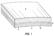
- Figure 1 an enlarged perspective view of an embodiment of ceramic abradable/insulating composition 10 (or coating 10) according to the present invention. This view also shows a cross section of ceramic insulating coating 10 placed on a substrate 8 of ceramic matrix composite and kept in place with a layer of adhesive 9.
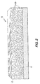
- FIG. 2 shows an enlarged perspective view, depicting the cross section, of a ceramic abradable coating 10.
- the coating 10 comprises hollow oxide-based spheres 20 of various dimensions, having minor sphere contact, in a combination 12 of a phosphate binder and various oxide filler powders.
- the phosphate binder "bridges" the gaps between the spheres 20 and the oxide filler powders.
- the spheres 20 are manufactured at high enough temperatures to make them stable at 1600°C, depending on the particular composition of the coating 10. Firing temperatures up to 1600°C are used to create the coating, which is dimensionally stable, chemically stable and erosion resistant.
- the coating 10 achieves improved erosion resistance by introducing closed porosity on a macroscopic scale with a relatively dense arrangement of spheres 20. As shown, there are about twelve to fifteen instances of sphere contact.
- the spheres 20 of Figure 2 are arranged so that each sphere 20 is in contact with at least one other sphere 20. More preferably, the spheres 20 are arranged so that each sphere 20 is in contact with several other spheres 20, i.e., at least 3 or 4 spheres 20. This provides the improved dimensional stability, especially at elevated temperatures near 1600°C. Sphere contact such as that present in the coating 10 and the resulting dimensional stability is not achieved by prior art coatings.
- Oxide filler powders in combination with the phosphate binder can be varied to control properties of the coating 10.
- Specific coating systems may be formulated to cover a range of coefficients of thermal expansion (CTE).
- CTE coefficients of thermal expansion
- the CTE of the coating 10 must be as close as practically possible to the CTE of the substrate 8 for the coating 10 to remain in place on the substrate 8.
- Various properties of exemplary coatings 10, A and B, are shown in Table 1.
- Material A B Use Temp ( N C) 1200 1600 CTE ( 10 -6 mm/mm N C) 5.85 5.85 Thermal Conductivity (W/mK) at 1400 N C 1.27 2.21 Erosion Resistance (g/kg) at 1100 N C 7.5 4.5
- the hollow oxide-based spheres 20 of the coating material of the present invention can be made of either Mullite, Alumina, stabilized Zirconia (usually Yttria stabilized Zirconia) or any combination thereof.
- the preferred range of diameters of the Mullite spheres is approximately 0.4 to approximately 1.8 mm, and more preferably approximately 0.8 to approximately 1.4 mm.
- the preferred range of diameters of the Alumina spheres is approximately 0.3 to approximately 1 mm.
- the preferred range of diameters of the stabilized Zirconia spheres is approximately 0.6 to approximately 1.2 mm, and more preferably approximately 0.8 to approximately 1 mm.
- the preferable weight percentage of spheres 20 in the coating 10 is 32% ⁇ 10%, more preferably 32% ⁇ 5%, and even more preferably approximately 32%.
- the preferable weight percentage of spheres 20 in the coating 10 is 63% ⁇ 15%, more preferably 63% ⁇ 10%, even more preferably 63% ⁇ 5%, and most preferably approximately 63%.
- the preferable weight percentage of spheres 20 in the coating 10 is 58% ⁇ 15%, more preferably 58% ⁇ 10%, even more preferably 58% ⁇ 5%, and most preferably approximately 58%.
- Tailoring a particular coating to obtain a particular CTE to "match" the CTE of the intended substrate 8 is achieved by varying the combination of spheres 20.
- monolithic stabilized Zirconia spheres have the highest CTE (approximately 10 ⁇ 10 -6 mm/mm°C)
- monolithic Mullite spheres have the lowest (approximately 5.7 ⁇ 10 -6 mm/mm°C)
- monolithic Alumina spheres have an intermediate value (approximately 8.0 ⁇ 10 -6 mm/mm°C).
- a preferred combination of spheres 20 is 20% Mullite and 80% Alumina by volume. As displayed in Table 2, this sphere composition yields a % linear change of 0.5972, which "matches" a value of 0.5934 for Composite A (an oxide-based CMC material) and a value of 0.6031 for composite B. For Composite C (a high silica containing oxide-based composite material), an all mullite sphere composition is preferred.
- Sphere Composition Volumetric Ratio % Linear Change at 1000°C Oxide/Oxide Substrate Composition (% Linear Change at 1000°C) Mullite 100 0.5657 0.5631 (C) Mullite and Stabilized Zirconia 50/50 0.5660 Mullite and Alumina 50/50 0.5763 Mullite and Alumina 20/80 0.5972 0.5934 (A) and 0.6031 (B) Mullite and Alumina 10/90 0.6210 Mullite and Alumina 5/95 0.6337 Alumina 100 0.6380 Stabilized Zirconia 100 0.7325
- the oxide filler powders can be Alumina, Mullite, Ceria, Hafnia or any combination thereof.
- Alumina or Mullite is used as the filler powder, and most preferably, Mullite is used because of its superior high temperature properties.
- the weight percentage of the oxide filler powder in the coating 10 is 32% ⁇ 15%, more preferably 32% ⁇ 10%, even more preferably 32% ⁇ 5%, and most preferably approximately 32%.
- the preferred weight percentages of the oxide filler powders vary because of the different atomic mass and particle size of each.
- the phosphate binder is Aluminum Ortho-Phosphate in a weight percentage of 31% ⁇ 15%, more preferably 31% ⁇ 10%, even more preferably 31% ⁇ 5%, and most preferably approximately 31%.
- a combination of Aluminum Ortho-Phosphate binder and Mullite filler powder has a viscosity of approximately 9,000 centipoise, measured with a Brookfield® RV viscometer having a spindle No. of 7 and a rpm of 20.
- the manufacturing process for the coating 10 of the present invention comprises the following steps: (1) mixing a slurry, (2) casting the slurry, (3) controlled drying, (4) removal of the "green" body, (5) firing, and (6) machining.
- the mixture is formulated such that the end product possesses a CTE practically identical to that of the CMC substrate 8.
- the process starts with the mixing of raw materials to form a viscous slurry and is accomplished in two stages.
- Aluminum Ortho-Phosphate and the filler powder is mixed to an exact formulation of 50% aqueous solution of Aluminum Ortho-Phosphate and is stored air-tight (with a shelf life of up to 2 months). Alter-natively, one can start with a 50% aqueous solution of Aluminum Ortho-Phosphate.
- the "green” bodies are carefully transferred to a drying oven (at approximately 80°C). In a preferred procedure, before drying, the "green" bodies are shaped to conform to the contour of a mating substrate surface. This step will achieve near net shaping capability. After drying, the "green” bodies are then transferred to the firing oven. During firing, a slow heating rate is used with a dwell at approximately 250°C which ensures that all of the free water is removed by this stage.
- the molds are recycled after the "green" bodies have been removed. This is achieved by washing out the leached phosphate with running water followed by oven drying. When fully dry, the dry weight of the mold must be within approximately 1% of the original dry weight in order for the mold to be used again. It can be expected to reuse a mold up to 12 times.
- the phosphate binder may exist in a glassy form, which is compliant during the firing process. This may provide the potential for shape forming during the first firing.
- a phosphate "bridge" is produced that gives a compliant matrix that can be used as a displacement type abradable seal.
- the phosphate "bridge" network that connects the constituents of the material system (the particles and spheres) is significantly modified to form more localized and densified phosphate agglomerations within the microstructure.
- a material system with new properties results from this change that retains up to 80% of its room temperature strength at 1400°C, has similar thermal conductivity and excellent erosion resistance (approximately a factor of 2 times better than currently available TBC systems used on metallic substrates).
- the material is fired stand alone and then ground to shape prior to bonding to the substrate 8.
- the adhesive 9 will vary according to the substrate 8. Direct coating onto the substrate 8, however, is also possible utilizing the substrate 8 and/or in-situ curing in the application environment.
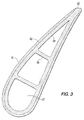
- FIG. 3 shows a cross-sectional view of a stationary vane 30 with a coating 10 of the present invention.
- the vane 30 has an inner surface 28 and an outer surface 32, upon which the coating 10 is bonded.
- the stationary vane 30 further comprises an adhesive 9 for bonding the composition 10 to the outer surface 32.
- the vane 30, as well as other turbine components utilizing the composition 10 of the present invention can be made from any variety of CMCs capable of surviving in oxidizing atmospheres at moderate temperatures (around 1200°C) under moderate stress (up to 100 MPA).
- Such materials include, but are not limited to, oxide matrix composites (e.g., Mullite, Aluminosilicate and Alumina), Silicon Carbide matrix composites (made by techniques such as chemical vapor infiltration or melt-infiltration), Silicon Nitride matrix composites (made by means such as reaction bonding, nitriding, hot pressing or pressureless sintering).
- the coating 10 is performed by forming the coating 10 separately and subsequently bonding the coating 10 to the substrate 8 using Aluminum Phosphate-based adhesives cured at intermediate temperatures, i.e., around 800°C-1200°C. Coatings of mullite or alumina may be applied to the substrate 8 prior to bonding to prevent fiber damage during curing and/or to facilitate the bonding process. These coatings are especially desirable when bonding to non-oxide substrates 8. In most preferred embodiments of the present invention, the coating 10 is applied in its "green" (uncured) state'to the surface of the composite and co-cured with the composite in-situ.
- Construction of the vane 30 need not be customized for application of the coatings 10 and includes any airfoil cross-section with or without integral platforms (external to the airfoil), and with or without internal stiffening ribs 26.
- the thermal conductivity of the ceramic insulation 10 of the present invention ranges from 1-2 W/mK depending upon the specific composition of spheres and filler powders, their relative amounts, and the final firing temperature used.
- the coating 10 is used in thicknesses greater than 1 mm, preferably 2-6 mm, and more preferably 2-3 mm. Cooling of the inner wall 28 of the vane 30 is achieved by convection, e.g., via direct impingement through supply baffles situated in the interior chambers 27 of the vane 30, using air directed from the compressor exit.
- the vane 30 consists of a 2 mm thick insulating coating 10 with a 4 mm thick CMC wall.
- Table 4 provides a one-dimensional comparison of this preferred embodiment in a high temperature (1600°C) engine environment with a state-of-the-art, thin-walled, metallic vane with a conventional thermal barrier coating.
- the maximum substrate temperature is at 1200°C
- the maximum coating temperature is 1579°C in a high temperature environment of 1600°C.
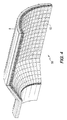
- a combustor 50 made with the coating 10 of the present invention is shown in Figure 4.
- the combustor 50 is an axially-symmetric component comprised of the insulating coating 10 of the present invention, serving as a combustor liner, bonded to the inner surface of. an outer structural member of CMC 8.
- the combustor 50 may or may not comprise integral flanges, attachment points, conical sections or other geometric features.
- the combustor 50 further comprises an adhesive 9 for bonding the composition 10 to the inner surface of the combustor 50 (or cylinder).
- the insulating coating 10 is deposited in its "green" state directly onto the uncured ceramic composite 8 and the two are co-cured.
- the design of the hybrid structure of the combustor 50 is intended to achieve maximum inner surface temperature to stabilize combustion and minimize unwanted emissions.
- the insulation 10 can be formed or deposited in varying thicknesses to control the temperatures and thermal stresses of the system.
- the insulation 10 is graded in thickness along the axial length of the combustor to coincide with the combustion flame position and internal temperature profile.
- the ability of the insulating coating 10 to withstand temperatures near 1600°C means that hot-wall combustion can occur, allowing leaner combustion mixtures, lower overall combustion temperatures, and consequently lower NOx emissions.
- a combustor transition duct (or transition), which is well known in the art, can have an insulating coating of the present invention.
- the transition can comprise an insulating coating bonded to the inside surface of an outer structural member of ceramic matrix composite such that hot combustion exhaust gases are in contact only with the insulating coating.
- the transition can further comprise an adhesive for bonding an insulating coating to the inner surface of the transition.
- the coating can be applied in its "green" state to the inner surface of the transition and co-cured with the composite in-situ.
- the ability of the insulating member to withstand temperatures near 1600°C means that passive cooling methods can be employed, resulting in lower cost components and increased engine efficiency.
- the insulating coating thickness can be varied around the component to account for variations in cooling patterns from the passive cooling, thus maintaining uniform temperatures of the structural component and minimizing stresses.
- Higher wall temperatures allowed by the hybrid construction of the transition also contribute to reduced emissions of carbon monoxide and unburned hydrocarbons. Reduction in cooling flows relative to conventional metallic designs for the transition of the present invention are similar to that shown in Table 4 for the vane 30 of Figure 3.
- Turbine blades are usually mounted on a rotor disk, as is well known in the art.
- the blade tip is located just inside the inner wall of the turbine shroud, upon which the ceramic abradable coating can be bonded.
- the tips of the rotating blades can contact the abradable coating and carve precisely-defined grooves in the coating without contacting the shroud itself.
- the shroud can be made from any variety of CMCs capable of surviving in oxidizing atmospheres at moderate temperatures, i.e., slightly greater than or equal to 1200 C, under moderate stress (approximately 100 MPa).
- application of the coating 10 is performed in the same manner as is performed for application on a stationary vane 30.
- the blade tip seal can further comprise an adhesive for bonding the composition to the inner surface of the shroud.
- the coating is applied in its "green" state to the inner surface of the shroud and co-cured with the composite in-situ.
- the construction or shape of the inner wall of the shroud need not be customized for application of the coating of the present invention.
- a typical inner wall having a thickness of 8 mm would utilize a 3 mm thick coating.
- Use of the coating not only would provide a seal for the turbine blade tip with its abradability, but would provide insulation for the inner wall of the ceramic shroud at elevated temperatures such as 1600°C.
- the coating of the present invention provides insulation for gas turbine components made of moderate temperature ceramic matrix composites so that the components can withstand temperatures near 1600°C without the use of thermal barrier coatings and reduces the need for cooling methods.
- a composition according of the present invention is stable preferably at temperatures greater than approximately 1300°C, and more preferably at temperatures up to approximately 1600°C.
- a composition according to the present invention stable at temperatures greater than approximately 1600°C is possible.
Landscapes
- Chemical & Material Sciences (AREA)
- Engineering & Computer Science (AREA)
- Ceramic Engineering (AREA)
- Materials Engineering (AREA)
- Structural Engineering (AREA)
- Organic Chemistry (AREA)
- Mechanical Engineering (AREA)
- General Engineering & Computer Science (AREA)
- Chemical Kinetics & Catalysis (AREA)
- Inorganic Chemistry (AREA)
- Turbine Rotor Nozzle Sealing (AREA)
Applications Claiming Priority (3)
| Application Number | Priority Date | Filing Date | Title |
|---|---|---|---|
| US49369 | 1998-03-27 | ||
| US09/049,369 US6197424B1 (en) | 1998-03-27 | 1998-03-27 | Use of high temperature insulation for ceramic matrix composites in gas turbines |
| PCT/US1999/003111 WO1999048837A1 (en) | 1998-03-27 | 1999-02-11 | Use of high temperature insulation for ceramic matrix composites in gas turbines |
Publications (2)
| Publication Number | Publication Date |
|---|---|
| EP1068161A1 EP1068161A1 (en) | 2001-01-17 |
| EP1068161B1 true EP1068161B1 (en) | 2002-05-08 |
Family
ID=21959450
Family Applications (1)
| Application Number | Title | Priority Date | Filing Date |
|---|---|---|---|
| EP99910952A Expired - Lifetime EP1068161B1 (en) | 1998-03-27 | 1999-02-11 | Use of high temperature insulation for ceramic matrix composites in gas turbines |
Country Status (6)
| Country | Link |
|---|---|
| US (1) | US6197424B1 (enExample) |
| EP (1) | EP1068161B1 (enExample) |
| JP (1) | JP4318858B2 (enExample) |
| KR (1) | KR100527685B1 (enExample) |
| DE (1) | DE69901440T2 (enExample) |
| WO (1) | WO1999048837A1 (enExample) |
Families Citing this family (148)
| Publication number | Priority date | Publication date | Assignee | Title |
|---|---|---|---|---|
| US7067181B2 (en) | 2003-08-05 | 2006-06-27 | Siemens Power Generation, Inc. | Insulating ceramic based on partially filled shapes |
| US6977060B1 (en) * | 2000-03-28 | 2005-12-20 | Siemens Westinghouse Power Corporation | Method for making a high temperature erosion resistant coating and material containing compacted hollow geometric shapes |
| US6676783B1 (en) * | 1998-03-27 | 2004-01-13 | Siemens Westinghouse Power Corporation | High temperature insulation for ceramic matrix composites |
| US6641907B1 (en) * | 1999-12-20 | 2003-11-04 | Siemens Westinghouse Power Corporation | High temperature erosion resistant coating and material containing compacted hollow geometric shapes |
| US7563504B2 (en) * | 1998-03-27 | 2009-07-21 | Siemens Energy, Inc. | Utilization of discontinuous fibers for improving properties of high temperature insulation of ceramic matrix composites |
| US6733907B2 (en) | 1998-03-27 | 2004-05-11 | Siemens Westinghouse Power Corporation | Hybrid ceramic material composed of insulating and structural ceramic layers |
| US6485848B1 (en) * | 1998-04-27 | 2002-11-26 | General Electric Company | Coated article and method of making |
| US6697130B2 (en) * | 2001-01-16 | 2004-02-24 | Visteon Global Technologies, Inc. | Flexible led backlighting circuit |
| US6746755B2 (en) * | 2001-09-24 | 2004-06-08 | Siemens Westinghouse Power Corporation | Ceramic matrix composite structure having integral cooling passages and method of manufacture |
| US6884384B2 (en) | 2001-09-27 | 2005-04-26 | Siemens Westinghouse Power Corporation | Method for making a high temperature erosion resistant material containing compacted hollow geometric shapes |
| US20030112931A1 (en) * | 2001-12-19 | 2003-06-19 | Wendell Brown | Facilitating navigation of an interactive voice response (IVR) menu to establish a telephone connection |
| US6495207B1 (en) | 2001-12-21 | 2002-12-17 | Pratt & Whitney Canada Corp. | Method of manufacturing a composite wall |
| US6759151B1 (en) * | 2002-05-22 | 2004-07-06 | The United States Of America As Represented By The Administrator Of The National Aeronautics And Space Administration | Multilayer article characterized by low coefficient of thermal expansion outer layer |
| US6709230B2 (en) * | 2002-05-31 | 2004-03-23 | Siemens Westinghouse Power Corporation | Ceramic matrix composite gas turbine vane |
| US6648597B1 (en) | 2002-05-31 | 2003-11-18 | Siemens Westinghouse Power Corporation | Ceramic matrix composite turbine vane |
| GB0226997D0 (en) * | 2002-11-19 | 2002-12-24 | Welding Inst | Heat resistant product |
| JP2004036443A (ja) * | 2002-07-02 | 2004-02-05 | Ishikawajima Harima Heavy Ind Co Ltd | ガスタービンシュラウド構造 |
| US6929852B2 (en) * | 2002-08-08 | 2005-08-16 | Siemens Westinghouse Power Corporation | Protective overlayer for ceramics |
| DE10239631A1 (de) * | 2002-08-23 | 2004-03-04 | Carcoustics Tech Center Gmbh | Isolierbauteil zur Wärme- und/oder Schallisolierung mit feuerhemmender Beschichtung |
| US6758653B2 (en) | 2002-09-09 | 2004-07-06 | Siemens Westinghouse Power Corporation | Ceramic matrix composite component for a gas turbine engine |
| US7093359B2 (en) | 2002-09-17 | 2006-08-22 | Siemens Westinghouse Power Corporation | Composite structure formed by CMC-on-insulation process |
| US9068464B2 (en) * | 2002-09-17 | 2015-06-30 | Siemens Energy, Inc. | Method of joining ceramic parts and articles so formed |
| US7582359B2 (en) * | 2002-09-23 | 2009-09-01 | Siemens Energy, Inc. | Apparatus and method of monitoring operating parameters of a gas turbine |
| US7572524B2 (en) * | 2002-09-23 | 2009-08-11 | Siemens Energy, Inc. | Method of instrumenting a component |
| US8151623B2 (en) | 2002-09-23 | 2012-04-10 | Siemens Energy, Inc. | Sensor for quantifying widening reduction wear on a surface |
| US7270890B2 (en) | 2002-09-23 | 2007-09-18 | Siemens Power Generation, Inc. | Wear monitoring system with embedded conductors |
| US7618712B2 (en) * | 2002-09-23 | 2009-11-17 | Siemens Energy, Inc. | Apparatus and method of detecting wear in an abradable coating system |
| US6838157B2 (en) | 2002-09-23 | 2005-01-04 | Siemens Westinghouse Power Corporation | Method and apparatus for instrumenting a gas turbine component having a barrier coating |
| US20050198967A1 (en) * | 2002-09-23 | 2005-09-15 | Siemens Westinghouse Power Corp. | Smart component for use in an operating environment |
| US7094027B2 (en) * | 2002-11-27 | 2006-08-22 | General Electric Company | Row of long and short chord length and high and low temperature capability turbine airfoils |
| US6893750B2 (en) * | 2002-12-12 | 2005-05-17 | General Electric Company | Thermal barrier coating protected by alumina and method for preparing same |
| US6767659B1 (en) | 2003-02-27 | 2004-07-27 | Siemens Westinghouse Power Corporation | Backside radiative cooled ceramic matrix composite component |
| US7871716B2 (en) * | 2003-04-25 | 2011-01-18 | Siemens Energy, Inc. | Damage tolerant gas turbine component |
| US7311790B2 (en) * | 2003-04-25 | 2007-12-25 | Siemens Power Generation, Inc. | Hybrid structure using ceramic tiles and method of manufacture |
| US7198860B2 (en) * | 2003-04-25 | 2007-04-03 | Siemens Power Generation, Inc. | Ceramic tile insulation for gas turbine component |
| US7985493B2 (en) * | 2003-09-22 | 2011-07-26 | Siemens Energy, Inc. | High temperature insulation and insulated article |
| US7108925B2 (en) * | 2003-09-22 | 2006-09-19 | Siemens Power Generation, Inc. | High temperature insulation utilizing zirconia-hafnia |
| US7064825B2 (en) * | 2003-11-25 | 2006-06-20 | General Electric Company | Methods and apparatus for evaluating rotary machinery |
| US6997673B2 (en) * | 2003-12-11 | 2006-02-14 | Honeywell International, Inc. | Gas turbine high temperature turbine blade outer air seal assembly |
| US8315834B2 (en) * | 2003-12-17 | 2012-11-20 | Siemens Energy, Inc. | System and method for measuring coating thickness |
| US7351364B2 (en) * | 2004-01-29 | 2008-04-01 | Siemens Power Generation, Inc. | Method of manufacturing a hybrid structure |
| US7066717B2 (en) * | 2004-04-22 | 2006-06-27 | Siemens Power Generation, Inc. | Ceramic matrix composite airfoil trailing edge arrangement |
| US7334330B2 (en) * | 2004-04-28 | 2008-02-26 | Siemens Power Generation, Inc. | Thermally insulating layer incorporating a distinguishing agent and method for inspecting the same |
| DE102004023623A1 (de) * | 2004-05-10 | 2005-12-01 | Alstom Technology Ltd | Strömungsmaschinenschaufel |
| US8742944B2 (en) * | 2004-06-21 | 2014-06-03 | Siemens Energy, Inc. | Apparatus and method of monitoring operating parameters of a gas turbine |
| US8004423B2 (en) * | 2004-06-21 | 2011-08-23 | Siemens Energy, Inc. | Instrumented component for use in an operating environment |
| US7402347B2 (en) * | 2004-12-02 | 2008-07-22 | Siemens Power Generation, Inc. | In-situ formed thermal barrier coating for a ceramic component |
| US7247002B2 (en) * | 2004-12-02 | 2007-07-24 | Siemens Power Generation, Inc. | Lamellate CMC structure with interlock to metallic support structure |
| US7314674B2 (en) | 2004-12-15 | 2008-01-01 | General Electric Company | Corrosion resistant coating composition, coated turbine component and method for coating same |
| US7310938B2 (en) * | 2004-12-16 | 2007-12-25 | Siemens Power Generation, Inc. | Cooled gas turbine transition duct |
| US7435058B2 (en) * | 2005-01-18 | 2008-10-14 | Siemens Power Generation, Inc. | Ceramic matrix composite vane with chordwise stiffener |
| US7449254B2 (en) * | 2005-01-21 | 2008-11-11 | General Electric Company | Environmental barrier coating with physical barrier layer for silicon-comprising materials |
| US7258530B2 (en) * | 2005-01-21 | 2007-08-21 | Siemens Power Generation, Inc. | CMC component and method of fabrication |
| US20060166019A1 (en) * | 2005-01-21 | 2006-07-27 | Irene Spitsberg | Thermal/environmental barrier coating for silicon-comprising materials |
| US7326468B2 (en) * | 2005-01-21 | 2008-02-05 | General Electric Company | Thermal/environmental barrier coating for silicon-comprising materials |
| US7115327B2 (en) | 2005-01-21 | 2006-10-03 | General Electric Company | Thermal/environmental barrier coating with transition layer for silicon-comprising materials |
| US7115326B2 (en) * | 2005-01-21 | 2006-10-03 | General Electric Company | Thermal/environmental barrier coating with transition layer for silicon-comprising materials |
| US7300621B2 (en) * | 2005-03-16 | 2007-11-27 | Siemens Power Generation, Inc. | Method of making a ceramic matrix composite utilizing partially stabilized fibers |
| US8137611B2 (en) * | 2005-03-17 | 2012-03-20 | Siemens Energy, Inc. | Processing method for solid core ceramic matrix composite airfoil |
| US20060280954A1 (en) * | 2005-06-13 | 2006-12-14 | Irene Spitsberg | Corrosion resistant sealant for outer EBL of silicon-containing substrate and processes for preparing same |
| US20060280955A1 (en) * | 2005-06-13 | 2006-12-14 | Irene Spitsberg | Corrosion resistant sealant for EBC of silicon-containing substrate and processes for preparing same |
| EP1907339A1 (en) | 2005-07-25 | 2008-04-09 | Siemens Power Generation, Inc. | Method of forming cmc component |
| US7785076B2 (en) * | 2005-08-30 | 2010-08-31 | Siemens Energy, Inc. | Refractory component with ceramic matrix composite skeleton |
| US7754342B2 (en) * | 2005-12-19 | 2010-07-13 | General Electric Company | Strain tolerant corrosion protecting coating and spray method of application |
| US7604867B2 (en) * | 2005-12-20 | 2009-10-20 | General Electric Company | Particulate corrosion resistant coating composition, coated turbine component and method for coating same |
| US20080026248A1 (en) * | 2006-01-27 | 2008-01-31 | Shekar Balagopal | Environmental and Thermal Barrier Coating to Provide Protection in Various Environments |
| US7942639B2 (en) * | 2006-03-31 | 2011-05-17 | General Electric Company | Hybrid bucket dovetail pocket design for mechanical retainment |
| US7604456B2 (en) * | 2006-04-11 | 2009-10-20 | Siemens Energy, Inc. | Vane shroud through-flow platform cover |
| US7534086B2 (en) * | 2006-05-05 | 2009-05-19 | Siemens Energy, Inc. | Multi-layer ring seal |
| US7726936B2 (en) * | 2006-07-25 | 2010-06-01 | Siemens Energy, Inc. | Turbine engine ring seal |
| US7641440B2 (en) * | 2006-08-31 | 2010-01-05 | Siemens Energy, Inc. | Cooling arrangement for CMC components with thermally conductive layer |
| US7368827B2 (en) * | 2006-09-06 | 2008-05-06 | Siemens Power Generation, Inc. | Electrical assembly for monitoring conditions in a combustion turbine operating environment |
| US7969323B2 (en) * | 2006-09-14 | 2011-06-28 | Siemens Energy, Inc. | Instrumented component for combustion turbine engine |
| US7753643B2 (en) * | 2006-09-22 | 2010-07-13 | Siemens Energy, Inc. | Stacked laminate bolted ring segment |
| US20080072569A1 (en) * | 2006-09-27 | 2008-03-27 | Thomas Ory Moniz | Guide vane and method of fabricating the same |
| US7950234B2 (en) * | 2006-10-13 | 2011-05-31 | Siemens Energy, Inc. | Ceramic matrix composite turbine engine components with unitary stiffening frame |
| US20100119777A1 (en) * | 2006-11-16 | 2010-05-13 | Siemens Power Generation, Inc. | Ceramic matrix composite surfaces with open features for improved bonding to coatings |
| US20080274336A1 (en) * | 2006-12-01 | 2008-11-06 | Siemens Power Generation, Inc. | High temperature insulation with enhanced abradability |
| US20080199661A1 (en) * | 2007-02-15 | 2008-08-21 | Siemens Power Generation, Inc. | Thermally insulated CMC structure with internal cooling |
| US7887300B2 (en) * | 2007-02-27 | 2011-02-15 | Siemens Energy, Inc. | CMC airfoil with thin trailing edge |
| US8257809B2 (en) | 2007-03-08 | 2012-09-04 | Siemens Energy, Inc. | CMC wall structure with integral cooling channels |
| US7819625B2 (en) * | 2007-05-07 | 2010-10-26 | Siemens Energy, Inc. | Abradable CMC stacked laminate ring segment for a gas turbine |
| US7648605B2 (en) * | 2007-05-17 | 2010-01-19 | Siemens Energy, Inc. | Process for applying a thermal barrier coating to a ceramic matrix composite |
| US9447503B2 (en) | 2007-05-30 | 2016-09-20 | United Technologies Corporation | Closed pore ceramic composite article |
| US20100021716A1 (en) * | 2007-06-19 | 2010-01-28 | Strock Christopher W | Thermal barrier system and bonding method |
| US7908867B2 (en) * | 2007-09-14 | 2011-03-22 | Siemens Energy, Inc. | Wavy CMC wall hybrid ceramic apparatus |
| US8128350B2 (en) * | 2007-09-21 | 2012-03-06 | Siemens Energy, Inc. | Stacked lamellae ceramic gas turbine ring segment component |
| US8797179B2 (en) * | 2007-11-08 | 2014-08-05 | Siemens Aktiengesellschaft | Instrumented component for wireless telemetry |
| US9071888B2 (en) * | 2007-11-08 | 2015-06-30 | Siemens Aktiengesellschaft | Instrumented component for wireless telemetry |
| US8519866B2 (en) | 2007-11-08 | 2013-08-27 | Siemens Energy, Inc. | Wireless telemetry for instrumented component |
| FR2929690B1 (fr) * | 2008-04-03 | 2012-08-17 | Snecma Propulsion Solide | Chambre de combustion sectorisee en cmc pour turbine a gaz |
| US8202588B2 (en) * | 2008-04-08 | 2012-06-19 | Siemens Energy, Inc. | Hybrid ceramic structure with internal cooling arrangements |
| US9127565B2 (en) * | 2008-04-16 | 2015-09-08 | Siemens Energy, Inc. | Apparatus comprising a CMC-comprising body and compliant porous element preloaded within an outer metal shell |
| US8366983B2 (en) * | 2008-07-22 | 2013-02-05 | Siemens Energy, Inc. | Method of manufacturing a thermal insulation article |
| US20100021643A1 (en) * | 2008-07-22 | 2010-01-28 | Siemens Power Generation, Inc. | Method of Forming a Turbine Engine Component Having a Vapor Resistant Layer |
| US8333812B2 (en) * | 2008-08-18 | 2012-12-18 | Forestwood Industrial, Inc. | Method and device for use of hollow spheres in a composite material |
| US20100047526A1 (en) * | 2008-08-19 | 2010-02-25 | Merrill Gary B | Subsurface inclusions of spheroids and methodology for strengthening a surface bond in a hybrid ceramic matrix composite structure |
| US20100047512A1 (en) * | 2008-08-19 | 2010-02-25 | Morrison Jay A | Methodology and tooling arrangements for strengthening a surface bond in a hybrid ceramic matrix composite structure |
| US8118546B2 (en) * | 2008-08-20 | 2012-02-21 | Siemens Energy, Inc. | Grid ceramic matrix composite structure for gas turbine shroud ring segment |
| US20100061847A1 (en) * | 2008-09-09 | 2010-03-11 | General Electric Company | Steam turbine part including ceramic matrix composite (cmc) |
| US20100069226A1 (en) * | 2008-09-17 | 2010-03-18 | General Electric Company | Rare earth phosphate bonded ceramics |
| US7704596B2 (en) | 2008-09-23 | 2010-04-27 | Siemens Energy, Inc. | Subsurface inclusion of fugitive objects and methodology for strengthening a surface bond in a hybrid ceramic matrix composite structure |
| US8382436B2 (en) * | 2009-01-06 | 2013-02-26 | General Electric Company | Non-integral turbine blade platforms and systems |
| US8251651B2 (en) | 2009-01-28 | 2012-08-28 | United Technologies Corporation | Segmented ceramic matrix composite turbine airfoil component |
| US8262345B2 (en) * | 2009-02-06 | 2012-09-11 | General Electric Company | Ceramic matrix composite turbine engine |
| US8177513B2 (en) * | 2009-02-18 | 2012-05-15 | General Electric Company | Method and apparatus for a structural outlet guide vane |
| GB0911500D0 (en) * | 2009-07-03 | 2009-08-12 | Rolls Royce Plc | Rotor blade over-tip leakage control |
| US8256088B2 (en) * | 2009-08-24 | 2012-09-04 | Siemens Energy, Inc. | Joining mechanism with stem tension and interlocked compression ring |
| US9085991B2 (en) * | 2009-11-06 | 2015-07-21 | Honeywell International Inc. | Protective coatings for ceramic matrix composite substrates and methods for improving the wear resistance thereof and coated articles produced therefrom |
| US8678771B2 (en) * | 2009-12-14 | 2014-03-25 | Siemens Energy, Inc. | Process for manufacturing a component |
| US8571813B2 (en) * | 2010-03-16 | 2013-10-29 | Siemens Energy, Inc. | Fiber optic sensor system for detecting surface wear |
| US9279340B2 (en) | 2010-03-23 | 2016-03-08 | General Electric Company | System and method for cooling gas turbine components |
| US20110232298A1 (en) * | 2010-03-23 | 2011-09-29 | General Electric Company | System and method for cooling gas turbine components |
| EP2418357A1 (en) | 2010-08-05 | 2012-02-15 | Siemens Aktiengesellschaft | Turbine airfoil and method for thermal barrier coating |
| US8347636B2 (en) | 2010-09-24 | 2013-01-08 | General Electric Company | Turbomachine including a ceramic matrix composite (CMC) bridge |
| DE102010047254B4 (de) * | 2010-10-01 | 2017-02-02 | Doka Industrie Gmbh | Holzverbundwerkstoff |
| US8790067B2 (en) | 2011-04-27 | 2014-07-29 | United Technologies Corporation | Blade clearance control using high-CTE and low-CTE ring members |
| US8739547B2 (en) | 2011-06-23 | 2014-06-03 | United Technologies Corporation | Gas turbine engine joint having a metallic member, a CMC member, and a ceramic key |
| US8864492B2 (en) | 2011-06-23 | 2014-10-21 | United Technologies Corporation | Reverse flow combustor duct attachment |
| US9335051B2 (en) | 2011-07-13 | 2016-05-10 | United Technologies Corporation | Ceramic matrix composite combustor vane ring assembly |
| US8920127B2 (en) | 2011-07-18 | 2014-12-30 | United Technologies Corporation | Turbine rotor non-metallic blade attachment |
| DE102011081323B3 (de) * | 2011-08-22 | 2012-06-21 | Siemens Aktiengesellschaft | Laufschaufel für eine Strömungsmaschine und Strömungsmaschine mit der Laufschaufel |
| CN104126028B (zh) | 2011-12-19 | 2017-02-22 | 普莱克斯 S.T.技术有限公司 | 生产热障和环境障涂层的含水浆料及制备和施用其的方法 |
| US9325388B2 (en) | 2012-06-21 | 2016-04-26 | Siemens Energy, Inc. | Wireless telemetry system including an induction power system |
| US20150004308A1 (en) * | 2013-06-27 | 2015-01-01 | Gary B. Merrill | Method for creating a textured bond coat surface |
| US10072503B2 (en) | 2013-08-14 | 2018-09-11 | Elwha Llc | Dual element turbine blade |
| US9420356B2 (en) | 2013-08-27 | 2016-08-16 | Siemens Energy, Inc. | Wireless power-receiving assembly for a telemetry system in a high-temperature environment of a combustion turbine engine |
| FR3016188B1 (fr) | 2014-01-09 | 2016-01-01 | Snecma | Protection contre le feu d'une piece en materiau composite tisse tridimensionnel |
| FR3023362A1 (fr) | 2014-07-04 | 2016-01-08 | Commissariat Energie Atomique | Absorbeur solaire selectif a couche epaisse de passivation anticorrosion et barriere thermique pour des applications hautes temperatures et son procede de realisation. |
| US10401028B2 (en) * | 2015-06-05 | 2019-09-03 | Rolls-Royce American Technologies, Inc. | Machinable CMC insert |
| US9810434B2 (en) * | 2016-01-21 | 2017-11-07 | Siemens Energy, Inc. | Transition duct system with arcuate ceramic liner for delivering hot-temperature gases in a combustion turbine engine |
| JP6550000B2 (ja) * | 2016-02-26 | 2019-07-24 | 三菱日立パワーシステムズ株式会社 | タービン翼 |
| EP3333142A1 (en) * | 2016-12-09 | 2018-06-13 | Siemens Aktiengesellschaft | Co-sintering a ceramic layer upon a cmc substrate |
| US10392946B2 (en) * | 2016-12-21 | 2019-08-27 | Rolls-Royce North American Technologies Inc. | Turbine blade with reinforced platform for composite material construction |
| EP3480011A1 (en) * | 2017-11-02 | 2019-05-08 | Siemens Aktiengesellschaft | Method to create a good bonding between a free standing thermal barrier coating and a green cmc |
| GB201804569D0 (en) | 2018-03-22 | 2018-05-09 | Rolls Royce Plc | Casing assembly |
| GB201813084D0 (en) * | 2018-08-10 | 2018-09-26 | Rolls Royce Plc | Efficent gas turbine engine |
| GB201813086D0 (en) | 2018-08-10 | 2018-09-26 | Rolls Royce Plc | Efficient gas turbine engine |
| GB201813082D0 (en) | 2018-08-10 | 2018-09-26 | Rolls Royce Plc | Efficient gas turbine engine |
| GB201813079D0 (en) | 2018-08-10 | 2018-09-26 | Rolls Royce Plc | Effcient gas turbine engine |
| GB201813081D0 (en) | 2018-08-10 | 2018-09-26 | Rolls Royce Plc | Efficient gas turbine engine |
| GB201813080D0 (en) * | 2018-08-10 | 2018-09-26 | Rolls Royce Plc | Effcient gas turbine engine |
| EP3683406B1 (en) | 2019-01-18 | 2023-11-29 | Ansaldo Energia Switzerland AG | Abradable hybrid material, particularly for seal elements in gas turbines, and manufacturing method thereof |
| US11060478B2 (en) * | 2019-05-30 | 2021-07-13 | Ford Global Technologies, Llc | System for an integrated hybrid composite cylinder head and turbine |
| US11286792B2 (en) * | 2019-07-30 | 2022-03-29 | Rolls-Royce Plc | Ceramic matrix composite vane with cooling holes and methods of making the same |
| US11333037B2 (en) * | 2020-02-06 | 2022-05-17 | Raytheon Technologies Corporation | Vane arc segment load path |
| US11203947B2 (en) * | 2020-05-08 | 2021-12-21 | Raytheon Technologies Corporation | Airfoil having internally cooled wall with liner and shell |
| US20240375394A1 (en) * | 2023-05-12 | 2024-11-14 | Raytheon Technologies Corporation | Ceramic matrix composite sandwich structure reinforced with z-tows |
Family Cites Families (19)
| Publication number | Priority date | Publication date | Assignee | Title |
|---|---|---|---|---|
| US3053694A (en) | 1961-02-20 | 1962-09-11 | Gen Electric | Abradable material |
| US3975165A (en) | 1973-12-26 | 1976-08-17 | Union Carbide Corporation | Graded metal-to-ceramic structure for high temperature abradable seal applications and a method of producing said |
| GB1525037A (en) | 1976-07-06 | 1978-09-20 | Inst Vysokikh Temperatur Akade | Manufacture of heat-resistant materials |
| US4177308A (en) | 1978-08-10 | 1979-12-04 | The United States Of America As Represented By The Secretary Of The Air Force | Non-combustible high temperature abradable seal material |
| US4247249A (en) | 1978-09-22 | 1981-01-27 | General Electric Company | Turbine engine shroud |
| US4269903A (en) | 1979-09-06 | 1981-05-26 | General Motors Corporation | Abradable ceramic seal and method of making same |
| US4374173A (en) | 1979-11-06 | 1983-02-15 | Sherritt Gordon Mines Limited | Composite powders sprayable to form abradable seal coatings |
| DE8013163U1 (de) | 1980-05-16 | 1988-10-13 | MTU Motoren- und Turbinen-Union München GmbH, 8000 München | Gehäuse für eine thermische Turbomaschine mit einer wärmedämmenden Auskleidung |
| US4521496A (en) | 1980-07-24 | 1985-06-04 | Sara Raymond V | Stress relieved metal/ceramic abradable seals |
| DE3307749A1 (de) | 1982-03-05 | 1983-10-13 | Rolls-Royce Ltd., London | Bauteil mit einem kompositwerkstoff-ueberzug und verfahren zum aufbringen des ueberzugs |
| US4690763A (en) | 1982-09-29 | 1987-09-01 | Swiss Aluminium Ltd. | Filter medium in the form of a stable porous body |
| US4704332A (en) | 1982-11-01 | 1987-11-03 | United Technologies Corporation | Lightweight fiber reinforced high temperature stable glass-ceramic abradable seal |
| US4639388A (en) | 1985-02-12 | 1987-01-27 | Chromalloy American Corporation | Ceramic-metal composites |
| US4867639A (en) | 1987-09-22 | 1989-09-19 | Allied-Signal Inc. | Abradable shroud coating |
| US5064727A (en) | 1990-01-19 | 1991-11-12 | Avco Corporation | Abradable hybrid ceramic wall structures |
| US5196471A (en) | 1990-11-19 | 1993-03-23 | Sulzer Plasma Technik, Inc. | Thermal spray powders for abradable coatings, abradable coatings containing solid lubricants and methods of fabricating abradable coatings |
| WO1993024672A1 (en) | 1992-05-29 | 1993-12-09 | United Technologies Corporation | Ceramic thermal barrier coating for rapid thermal cycling applications |
| US5472315A (en) | 1993-11-09 | 1995-12-05 | Sundstrand Corporation | Abradable coating in a gas turbine engine |
| GB9513252D0 (en) * | 1995-06-29 | 1995-09-06 | Rolls Royce Plc | An abradable composition |
-
1998
- 1998-03-27 US US09/049,369 patent/US6197424B1/en not_active Expired - Lifetime
-
1999
- 1999-02-11 JP JP2000537825A patent/JP4318858B2/ja not_active Expired - Fee Related
- 1999-02-11 WO PCT/US1999/003111 patent/WO1999048837A1/en not_active Ceased
- 1999-02-11 DE DE69901440T patent/DE69901440T2/de not_active Expired - Lifetime
- 1999-02-11 EP EP99910952A patent/EP1068161B1/en not_active Expired - Lifetime
- 1999-02-11 KR KR10-2000-7010756A patent/KR100527685B1/ko not_active Expired - Fee Related
Also Published As
| Publication number | Publication date |
|---|---|
| WO1999048837A1 (en) | 1999-09-30 |
| US6197424B1 (en) | 2001-03-06 |
| KR20010042230A (ko) | 2001-05-25 |
| DE69901440D1 (de) | 2002-06-13 |
| JP2002507688A (ja) | 2002-03-12 |
| DE69901440T2 (de) | 2002-11-21 |
| KR100527685B1 (ko) | 2005-11-25 |
| EP1068161A1 (en) | 2001-01-17 |
| JP4318858B2 (ja) | 2009-08-26 |
Similar Documents
| Publication | Publication Date | Title |
|---|---|---|
| EP1068161B1 (en) | Use of high temperature insulation for ceramic matrix composites in gas turbines | |
| CA2461699C (en) | Hybrid ceramic material composed of insulating and structural ceramic layers | |
| EP1244605B1 (en) | High temperature erosion resistant coating and material containing compacted hollow geometric shapes | |
| RU2330162C2 (ru) | Высокотемпературная слоистая система для теплоотвода и способ для ее изготовления (варианты) | |
| US7247212B2 (en) | Orthogonal weaving for complex shape preforms | |
| US20250027414A1 (en) | Composite Component Modifications | |
| US20050111966A1 (en) | Construction of static structures for gas turbine engines | |
| EP4015771B1 (en) | Vane arc segment with thermal insulation element | |
| US11034842B2 (en) | Coating for improved surface finish | |
| WO2020018090A1 (en) | Hybrid components having an intermediate ceramic fiber material | |
| EP4379191A1 (en) | Seal slot with coating and method of coating a seal slot | |
| EP3683406B1 (en) | Abradable hybrid material, particularly for seal elements in gas turbines, and manufacturing method thereof | |
| JP7596067B2 (ja) | 表面仕上げ改善用のコーティング | |
| EP4653669A1 (en) | Abradable coating | |
| EP4325027B1 (en) | Airfoil with cmc liner with multi-piece monolithic ceramic shell | |
| EP4575187A1 (en) | Intercomponent seal arrangement for a gas turbine engine | |
| US11203947B2 (en) | Airfoil having internally cooled wall with liner and shell |
Legal Events
| Date | Code | Title | Description |
|---|---|---|---|
| PUAI | Public reference made under article 153(3) epc to a published international application that has entered the european phase |
Free format text: ORIGINAL CODE: 0009012 |
|
| 17P | Request for examination filed |
Effective date: 20000919 |
|
| AK | Designated contracting states |
Kind code of ref document: A1 Designated state(s): DE FR GB IT |
|
| GRAG | Despatch of communication of intention to grant |
Free format text: ORIGINAL CODE: EPIDOS AGRA |
|
| 17Q | First examination report despatched |
Effective date: 20010611 |
|
| GRAG | Despatch of communication of intention to grant |
Free format text: ORIGINAL CODE: EPIDOS AGRA |
|
| GRAH | Despatch of communication of intention to grant a patent |
Free format text: ORIGINAL CODE: EPIDOS IGRA |
|
| GRAH | Despatch of communication of intention to grant a patent |
Free format text: ORIGINAL CODE: EPIDOS IGRA |
|
| REG | Reference to a national code |
Ref country code: GB Ref legal event code: IF02 |
|
| GRAA | (expected) grant |
Free format text: ORIGINAL CODE: 0009210 |
|
| AK | Designated contracting states |
Kind code of ref document: B1 Designated state(s): DE FR GB IT |
|
| REF | Corresponds to: |
Ref document number: 69901440 Country of ref document: DE Date of ref document: 20020613 |
|
| ET | Fr: translation filed | ||
| PLBE | No opposition filed within time limit |
Free format text: ORIGINAL CODE: 0009261 |
|
| STAA | Information on the status of an ep patent application or granted ep patent |
Free format text: STATUS: NO OPPOSITION FILED WITHIN TIME LIMIT |
|
| 26N | No opposition filed |
Effective date: 20030211 |
|
| PG25 | Lapsed in a contracting state [announced via postgrant information from national office to epo] |
Ref country code: IT Free format text: LAPSE BECAUSE OF NON-PAYMENT OF DUE FEES Effective date: 20100211 |
|
| REG | Reference to a national code |
Ref country code: DE Ref legal event code: R082 Ref document number: 69901440 Country of ref document: DE Representative=s name: PETER BERG, DE |
|
| REG | Reference to a national code |
Ref country code: DE Ref legal event code: R082 Ref document number: 69901440 Country of ref document: DE Representative=s name: BERG, PETER, DIPL.-ING., DE Effective date: 20111028 Ref country code: DE Ref legal event code: R081 Ref document number: 69901440 Country of ref document: DE Owner name: SIEMENS ENERGY, INC., US Free format text: FORMER OWNER: SIEMENS WESTINGHOUSE POWER CORP., ORLANDO, US Effective date: 20111028 Ref country code: DE Ref legal event code: R081 Ref document number: 69901440 Country of ref document: DE Owner name: SIEMENS ENERGY, INC., ORLANDO, US Free format text: FORMER OWNER: SIEMENS WESTINGHOUSE POWER CORP., ORLANDO, FLA., US Effective date: 20111028 |
|
| REG | Reference to a national code |
Ref country code: FR Ref legal event code: CD Owner name: SIEMENS ENERGY, INC. Effective date: 20120413 |
|
| REG | Reference to a national code |
Ref country code: FR Ref legal event code: PLFP Year of fee payment: 18 |
|
| REG | Reference to a national code |
Ref country code: FR Ref legal event code: PLFP Year of fee payment: 19 |
|
| PGFP | Annual fee paid to national office [announced via postgrant information from national office to epo] |
Ref country code: FR Payment date: 20170222 Year of fee payment: 19 |
|
| PGFP | Annual fee paid to national office [announced via postgrant information from national office to epo] |
Ref country code: GB Payment date: 20170213 Year of fee payment: 19 |
|
| PGFP | Annual fee paid to national office [announced via postgrant information from national office to epo] |
Ref country code: IT Payment date: 20170224 Year of fee payment: 19 |
|
| PGFP | Annual fee paid to national office [announced via postgrant information from national office to epo] |
Ref country code: DE Payment date: 20170419 Year of fee payment: 19 |
|
| REG | Reference to a national code |
Ref country code: DE Ref legal event code: R119 Ref document number: 69901440 Country of ref document: DE |
|
| GBPC | Gb: european patent ceased through non-payment of renewal fee |
Effective date: 20180211 |
|
| REG | Reference to a national code |
Ref country code: FR Ref legal event code: ST Effective date: 20181031 |
|
| PG25 | Lapsed in a contracting state [announced via postgrant information from national office to epo] |
Ref country code: DE Free format text: LAPSE BECAUSE OF NON-PAYMENT OF DUE FEES Effective date: 20180901 |
|
| PG25 | Lapsed in a contracting state [announced via postgrant information from national office to epo] |
Ref country code: FR Free format text: LAPSE BECAUSE OF NON-PAYMENT OF DUE FEES Effective date: 20180228 Ref country code: IT Free format text: LAPSE BECAUSE OF NON-PAYMENT OF DUE FEES Effective date: 20180211 Ref country code: GB Free format text: LAPSE BECAUSE OF NON-PAYMENT OF DUE FEES Effective date: 20180211 |