EP1068022B1 - Atomising bowl and electrostatic rotary sprayhead unit equipped therewith - Google Patents
Atomising bowl and electrostatic rotary sprayhead unit equipped therewith Download PDFInfo
- Publication number
- EP1068022B1 EP1068022B1 EP99910470A EP99910470A EP1068022B1 EP 1068022 B1 EP1068022 B1 EP 1068022B1 EP 99910470 A EP99910470 A EP 99910470A EP 99910470 A EP99910470 A EP 99910470A EP 1068022 B1 EP1068022 B1 EP 1068022B1
- Authority
- EP
- European Patent Office
- Prior art keywords
- bowl
- atomising
- flange
- insert
- discharge
- Prior art date
- Legal status (The legal status is an assumption and is not a legal conclusion. Google has not performed a legal analysis and makes no representation as to the accuracy of the status listed.)
- Expired - Lifetime
Links
Images


Classifications
-
- B—PERFORMING OPERATIONS; TRANSPORTING
- B05—SPRAYING OR ATOMISING IN GENERAL; APPLYING FLUENT MATERIALS TO SURFACES, IN GENERAL
- B05B—SPRAYING APPARATUS; ATOMISING APPARATUS; NOZZLES
- B05B5/00—Electrostatic spraying apparatus; Spraying apparatus with means for charging the spray electrically; Apparatus for spraying liquids or other fluent materials by other electric means
- B05B5/025—Discharge apparatus, e.g. electrostatic spray guns
- B05B5/04—Discharge apparatus, e.g. electrostatic spray guns characterised by having rotary outlet or deflecting elements, i.e. spraying being also effected by centrifugal forces
-
- B—PERFORMING OPERATIONS; TRANSPORTING
- B05—SPRAYING OR ATOMISING IN GENERAL; APPLYING FLUENT MATERIALS TO SURFACES, IN GENERAL
- B05B—SPRAYING APPARATUS; ATOMISING APPARATUS; NOZZLES
- B05B3/00—Spraying or sprinkling apparatus with moving outlet elements or moving deflecting elements
- B05B3/02—Spraying or sprinkling apparatus with moving outlet elements or moving deflecting elements with rotating elements
- B05B3/10—Spraying or sprinkling apparatus with moving outlet elements or moving deflecting elements with rotating elements discharging over substantially the whole periphery of the rotating member, i.e. the spraying being effected by centrifugal forces
- B05B3/1035—Driving means; Parts thereof, e.g. turbine, shaft, bearings
- B05B3/1042—Means for connecting, e.g. reversibly, the rotating spray member to its driving shaft
-
- B—PERFORMING OPERATIONS; TRANSPORTING
- B05—SPRAYING OR ATOMISING IN GENERAL; APPLYING FLUENT MATERIALS TO SURFACES, IN GENERAL
- B05B—SPRAYING APPARATUS; ATOMISING APPARATUS; NOZZLES
- B05B3/00—Spraying or sprinkling apparatus with moving outlet elements or moving deflecting elements
- B05B3/02—Spraying or sprinkling apparatus with moving outlet elements or moving deflecting elements with rotating elements
- B05B3/10—Spraying or sprinkling apparatus with moving outlet elements or moving deflecting elements with rotating elements discharging over substantially the whole periphery of the rotating member, i.e. the spraying being effected by centrifugal forces
- B05B3/1064—Spraying or sprinkling apparatus with moving outlet elements or moving deflecting elements with rotating elements discharging over substantially the whole periphery of the rotating member, i.e. the spraying being effected by centrifugal forces the liquid or other fluent material to be sprayed being axially supplied to the rotating member through a hollow rotating shaft
-
- B—PERFORMING OPERATIONS; TRANSPORTING
- B05—SPRAYING OR ATOMISING IN GENERAL; APPLYING FLUENT MATERIALS TO SURFACES, IN GENERAL
- B05B—SPRAYING APPARATUS; ATOMISING APPARATUS; NOZZLES
- B05B5/00—Electrostatic spraying apparatus; Spraying apparatus with means for charging the spray electrically; Apparatus for spraying liquids or other fluent materials by other electric means
- B05B5/025—Discharge apparatus, e.g. electrostatic spray guns
- B05B5/04—Discharge apparatus, e.g. electrostatic spray guns characterised by having rotary outlet or deflecting elements, i.e. spraying being also effected by centrifugal forces
- B05B5/0403—Discharge apparatus, e.g. electrostatic spray guns characterised by having rotary outlet or deflecting elements, i.e. spraying being also effected by centrifugal forces characterised by the rotating member
- B05B5/0407—Discharge apparatus, e.g. electrostatic spray guns characterised by having rotary outlet or deflecting elements, i.e. spraying being also effected by centrifugal forces characterised by the rotating member with a spraying edge, e.g. like a cup or a bell
-
- B—PERFORMING OPERATIONS; TRANSPORTING
- B05—SPRAYING OR ATOMISING IN GENERAL; APPLYING FLUENT MATERIALS TO SURFACES, IN GENERAL
- B05B—SPRAYING APPARATUS; ATOMISING APPARATUS; NOZZLES
- B05B5/00—Electrostatic spraying apparatus; Spraying apparatus with means for charging the spray electrically; Apparatus for spraying liquids or other fluent materials by other electric means
- B05B5/025—Discharge apparatus, e.g. electrostatic spray guns
- B05B5/053—Arrangements for supplying power, e.g. charging power
- B05B5/0533—Electrodes specially adapted therefor; Arrangements of electrodes
Definitions
- the invention relates to a spray bowl and a electrostatic rotary coating product sprayer equipped with such a bowl.
- a bowl according to the preamble of claims 1 or 9 is known from document EP-A-094 796.
- Bowls made of insulating material do not allow do not electrostatically charge the coating material, so that additional means of charging must be provided coating product by Corona landfills or corona.
- the coating product load obtained is less effective, so that the effect of the electrostatic field on the particles of coating is lower, the deposit yield obtained being relatively small.
- Bowls made of a conductive material allow electrostatically charge the coating product when its flow in contact with the surfaces of the bowl which is brought to high voltage by any appropriate means. These bowls feature generally the disadvantage of building up capacities electrical hazards, potentially dangerous to a user and likely to create arcs suitable for starting a fire in the explosive atmosphere a coating booth.
- electrostatic coating materials and their devices are subjected to security tests pushed to ensure that they are not likely to cause an electric shock whose energy would greater than a predetermined threshold value.
- Some standards provide for example that the breakdown energy or discharge, between a part of the sprayer raised to high tension and a sphere of small radius arranged at a distance on the order of a centimeter, must be less than 0.24 mJ. A such value cannot be respected with a known bowl made of electrically conductive material because the edges and the flat surfaces which it comprises, in particular near the edge of the coating product, are likely to give rise to much higher energy discharges.
- the invention relates to a spray bowl for electrostatic rotary projector of product of coating according to claim 1 or 9.
- the flange which constitutes the part central bowl, authorizes a contact charge of the product coating in progress.
- the element (s) of discharge create privileged scent paths between the flange and the outside of the bowl, so that no build-up of energy is only possible at a level such as the energy of breakdown would exceed the allowable values.
- the bowl includes several regularly distributed discharge elements around its axis of rotation. This multiplicity of elements discharge allows to obtain, when powering the bowl, the desired effect with a symmetry of revolution around of the axis of rotation of the bowl, including in the absence of setting rotation. In addition, this distribution avoids an imbalance dynamics of the bowl, i.e. an unbalance not admissible to rotational speeds considered.
- the flange is bordered at its periphery external, by a generally annular part produced in an electrically more insulating material than the material of the flange and forming a spray edge or edge of the bowl and the current discharge element is formed by an insert made of an electrically more conductive material than the annular part and arranged in this annular part, in electrical contact with the flange, this insert extending to the vicinity of an external surface of the annular part.
- the annular part located at the periphery of the flange avoids risk of electric breakdown between flat surfaces brought to high voltage and a neighboring object brought to ground.
- the inserts which are advantageously but not necessarily metallic, constitute particularly discharge elements effective through the insulating or semiconductor layer produced by the annular part around the flange.
- the insert is partially received in a hole in the flange driver.
- This particularly simple construction ensures effective electrical contact between the flange and the insert, while ensuring its positioning in relation to others constituents of the bowl.
- the deflector carries at least one discharge element extending to an external surface, called the front face, of the deflector.
- the discharge element is an insert disposed along the axis of rotation of the bowl.
- the one or more inserts are or are needle shaped and have at least one tip-shaped end, this end being flush to the external surface of the annular part or the deflector.
- at least one insert carries a collar capable of cooperating with an internal shoulder a housing for receiving the insert.
- At least one insert has two shaped ends point, these ends being flush with two surfaces external of the annular part, these external surfaces being oriented respectively towards the axis of rotation and towards the outside of the bowl.
- the end of the insert close to the outer surface of the bowl is arranged near the spray edge. This provision is particularly advantageous, because it is near the spray edge that there is more risk than getting has an obstacle to ground, such as a hatch or door not closed on a motor vehicle body in progress coating.
- the discharge element is formed by a point shaped on the external surface of the flange.
- This aspect of the invention enables a bowl to be produced entirely conductive, particularly efficient for charging by coating product contact, while avoiding problems aforementioned discharge with potentially energy levels dangerous.
- the spikes formed by the elements of discharge are supplied with high voltage by the mass of the flaccid and constitute as many privileged points of discharge by scents.
- the point or points are formed in a single piece with the flange.
- the invention also relates to an electrostatic headlamp. coating product which includes a bowl such as previously described and electrical connection means of the flange of this bowl to a high voltage generator, this generator being able to detect variations in the corona current passing through the bowl discharge element (s).
- This projector meets the most demanding standards in terms of security, which corresponds to a very high dependability.
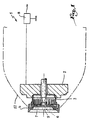
- an electrostatic rotary projector 1 of coating product comprises a rotor 2 driven in rotation by any suitable means and, in particular by an air turbine or a electric motor.
- the rotor 2 carries an elastic ring 3 which may conform to the technical teaching of EP-A-0 697 917.
- the elastic ring 3 makes it possible to make a bowl of spraying 4 of the rotor 2.
- the rotor 2 is crossed by a fixed duct 5 for supplying coating product to vicinity of a central orifice 6 for supplying the bowl 4 formed in a flange 7 extending generally perpendicular to the axis of rotation XX ′ of the rotor 2, of the ring 3 and of the bowl 4.
- the rotor 2 is made of a material electrically conductor, for example metallic, and connected by any means suitable for a high voltage generator 8.
- the ring 3 and the flange 7 are also made of materials electrically conductors, so that the high voltage from the generator 8 is transmitted to the flange 7.
- the flange 7 is therefore able to charge electrostatically, by contact, the coating product which flows on its surface when it is supplied with high voltage by generator 8 during operation of projector 1.
- the bowl 4 also includes a deflector 9 disposed opposite the outlet orifice of the conduit 5 relative to the flange 7, that is to say facing a surface 7 a , called the front face, of the flange 7.
- the deflector 9 is pierced with four conduits 10 allowing, during the cleaning phases of the bowl, the flow of a part of a solvent coming from the conduit 5 on its surface 9 a directed towards the outside and called the face before.
- the deflector 9 is immobilized with respect to the flange 7 by screws 11 passing through the flange 7 and penetrating into the rear bosses 9 b of the deflector 9.
- the piece 20 is advantageously glued to the flange 7. It is also noted that the respective shapes of the pieces 7 and 20 contribute to immobilization of the piece 20 on the flange 7 by cooperation of shapes.
- Needle-shaped metal inserts 22 are housed in eight blind holes 23 formed both in the part 20 and in the flange 7.
- Each insert 22 comprises a first end 22 a , in the shape of a point, disposed flush with the surface external 20 has the part 20 close to the spraying edge 21.
- the second end 22 b is inserted into the bottom of the hole 23 which is formed in the portion 7b of the flange 7.
- the inserts 22, which are metallic, are in permanently brought to the same electrical potential as the flange 7.
- the bowl includes several inserts 22 distributed around the axis XX 'allows to multiply the effect described above and to ensure symmetry around it this axis.
- a second series of eight inserts 25 is arranged through the part 20 and the external radial part 7 b of the flange 7, each insert 25 comprising a first end 25 a in point shape arranged in the immediate vicinity of the external part 20 a 1 of the external surface 20 a .
- the spikes 25 are inserts 25 are directed towards the rear of the bowl 4, in the direction of a cover outer surface 12 of the projector 1 shown in phantom in Figure 1.
- any object to ground can not be approached tips 25a through the hood 12 which is insulating, so that the cover limits the potential approach area of a ground object.
- Each insert 25 carries, at its second end 25 b , a head or flange 25 c capable of cooperating with a shoulder 26 a of a receiving hole 26 of the insert 25. This makes it possible to position the first end with precision 25 has the insert 25 relative to the external surface 20 a 1 of the part 20.
- a glue or resin plug 27 is advantageously disposed in the part of the bore 26 opposite the point 25 a , so that the part 20 a 2 of the external surface 20 a directed towards the axis XX 'does not have any irregularities in which the coating product could accumulate.
- an insert 28 is disposed in. the deflector 9 and comprises a first end 28 a , in the shape of a point, disposed flush with the front face 9 a of the deflector 9. If the deflector 9 is made of electrically conductive material, the insert 28 is brought to the same potential electrostatic than the flange 7, so that it is capable of generating a discharge line, as explained above with reference to the inserts 22 and 25. It should here be noted that, even if it is disposed within an electrically surface conductive raised to the high voltage through the bosses 9b, the tip of the insert 28 constitutes a privileged zone of discharge relative to the surface 9a of the deflector 9.
- the scent generated at the tips of inserts 25 and 28 are detected by the generator 8.
- the deflector 9 is made of electrically insulating material, in which case the insert 28 is brought to a floating potential.
- the tip 28 a is also used for the effluvium of the electrostatic charges drained by the insert 28 on the surface of the deflector 9.
- the insert 28 prevents the electrical capacity of the conduit 5, of its support and of the turbine associated with the rotor 2 from being discharged through the conduits 10 for flushing the front face 9 has deflector.
- the inserts 25 include a tapered tip at each end 25 a or 25 b .
- This also makes it possible to create a discharge line L "on the side of the surface 20 a 2 of the part 20 when a sphere S, at earth potential, is approached in the direction of the point 25 b .
- the ends in point 25 b avoid the creation of electric arcs or high energy discharges between the front circular edge 9 c of the deflector and an object grounded in the position of the sphere S in FIG. 5.
- the presence of the flange 25 c and the shoulder 26 a guarantees that the inserts 25 are not likely to be ejected from the bowl under the effect of the intense centrifugal forces which they undergo due to high rotation speeds of the spray bowl which can reach, or even exceed, 80,000 revolutions per minute.
- the material used for the manufacture of the flange 7 is advantageously based on aluminum, which allows it to have good dimensional stability, this property being essential when rotating the bowl at speed high.
- the material used for part 20 can be a resin based on polyoxymethylene.
- inserts 22, 25 and 28 can be made of steel or aluminum.
- the annular part 20 can also be produced in a semiconductor material, because it suffices that the part 20 has a higher resistivity than that of inserts 22 or 25 so that these constitute privileged routes of discharge.
- part 20 is made in an electrically insulating material, provision may be made for the inserts 22 and 25, or even insert 28, are produced in a semiconductor material.
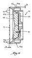
- the bowl 54 shown in Figure 6 can be mounted on the projector shown schematically in Figure 1.
- This bowl essentially comprises a flange 57 made of an electrically conductive material on which is fixed one. deflector 59 by means of several screws 61.
- This bowl differs from those of the previous embodiments essentially in that it does not include an annular piece more insulating than the flange 57, but on the contrary in that the flange 57 extends radially to the outside so as to form the spraying edge 71.
- Note 57c the outer peripheral surface of the flange 57.
- the points 72 to 75 a and 75 b constitute as many privileged zones for discharging by corona the electrical capacity constituted by the flange 57 as a whole.
- the variations in current consumption induced by the emanations, during the creation of a discharge line, in particular by approaching an object of ground, can be detected by the generator 8 mentioned with reference to the first embodiment.
- the points or pins 72, 75 a and 75 b have a height h relative to the spraying edge 71 or to the surfaces 57 c and 57 d of the order of 1 to 2 mm, which allows them to create zones discharge by fragrance without being dangerous for a user who handles the bowl 54.
- the deflector 59 can be equipped with a discharge insert by corona, or even provided, in its central part, with a point of the type of tips 72.
Landscapes
- Electrostatic Spraying Apparatus (AREA)
Abstract
Description
L'invention a trait à un bol de pulvérisation et à un
pulvérisateur rotatif électrostatique de produit de revêtement
équipé d'un tel bol. Un bol selon la préambule des revendications 1 ou 9
est connu du document EP-A-094 796.The invention relates to a spray bowl and a
electrostatic rotary coating product sprayer
equipped with such a bowl. A bowl according to the preamble of
Il est connu d'équiper un pulvérisateur rotatif de produit de revêtement d'un bol ou cloche solidaire du rotor d'une turbine d'entraínement en rotation, afin de former un nuage de produit de revêtement pulvérisé, ce nuage étant entraíné par un champ électrostatique et, éventuellement, par un écoulement d'air, en direction d'un objet à revêtir. Il existe essentiellement deux types de bols de pulvérisation, à savoir les bols de pulvérisation réalisés dans un matériau électriquement conducteur et les bols de pulvérisation réalisés dans un matériau électriquement isolant.It is known to equip a rotary product sprayer for coating a bowl or bell integral with the rotor of a rotational drive turbine, to form a cloud of sprayed coating product, this cloud being entrained by a electrostatic field and possibly by a flow air, towards an object to be coated. There are basically two types of spray bowls, namely bowls spraying material electrically conductor and the spray bowls made in a electrically insulating material.
Les bols réalisés dans un matériau isolant ne permettent pas de charger électrostatiquement le produit de revêtement, de sorte qu'il doit être prévu des moyens annexes de charge du produit de revêtement par décharges Corona ou effluves. La charge du produit de revêtement obtenue est moins efficace, de sorte que l'effet du champ électrostatique sur les particules de revêtement est moindre, le rendement de dépôt obtenu étant relativement faible.Bowls made of insulating material do not allow do not electrostatically charge the coating material, so that additional means of charging must be provided coating product by Corona landfills or corona. The coating product load obtained is less effective, so that the effect of the electrostatic field on the particles of coating is lower, the deposit yield obtained being relatively small.
Les bols réalisés dans un matériau conducteur permettent de charger électrostatiquement le produit du revêtement lors de son écoulement au contact des surfaces du bol qui est porté à la haute tension par tout moyen approprié. Ces bols présentent généralement l'inconvénient de constituer des capacités électriques importantes, potentiellement dangereuses pour un utilisateur et susceptibles de créer des arcs électriques propres à déclencher un incendie dans l'atmosphère explosive d'une cabine de revêtement.Bowls made of a conductive material allow electrostatically charge the coating product when its flow in contact with the surfaces of the bowl which is brought to high voltage by any appropriate means. These bowls feature generally the disadvantage of building up capacities electrical hazards, potentially dangerous to a user and likely to create arcs suitable for starting a fire in the explosive atmosphere a coating booth.
Par ailleurs, les matériels de revêtement électrostatique et leurs périphériques sont soumis à des tests de sécurité poussés afin de s'assurer qu'ils ne sont pas susceptibles de provoquer une décharge électrique dont l'énergie serait supérieure à une valeur de seuil prédéterminée. Certaines normes prévoient par exemple que l'énergie de claquage ou de décharge, entre une partie du pulvérisateur portée à la haute tension et une sphère de faible rayon disposée à une distance de l'ordre du centimètre, doit être inférieure à 0,24 mJ. Une telle valeur ne peut pas être respectée avec un bol connu réalisé en matériau électriquement conducteur car les arêtes et les surfaces planes qu'il comprend, notamment voisinage du bord de décharge du produit de revêtement, sont susceptibles de donner naissance à des décharges d'énergie bien supérieure.In addition, electrostatic coating materials and their devices are subjected to security tests pushed to ensure that they are not likely to cause an electric shock whose energy would greater than a predetermined threshold value. Some standards provide for example that the breakdown energy or discharge, between a part of the sprayer raised to high tension and a sphere of small radius arranged at a distance on the order of a centimeter, must be less than 0.24 mJ. A such value cannot be respected with a known bowl made of electrically conductive material because the edges and the flat surfaces which it comprises, in particular near the edge of the coating product, are likely to give rise to much higher energy discharges.
C'est à ces inconvénients qu'entend plus particulièrement remédier l'invention, en proposant un bol de pulvérisation permettant une charge par contact du produit de revêtement et pour lequel l'énergie de décharge ou "de claquage" est maintenue à un niveau inférieur à celui imposé par les normes les plus restrictives.It is to these disadvantages that we hear more particularly remedy the invention, by proposing a spray bowl allowing a contact charge of the coating product and for which the discharge or "breakdown" energy is maintained at a level lower than that imposed by the standards more restrictive.
Dans cet esprit, l'invention concerne un bol de pulvérisation
pour projecteur rotatif électrostatique de produit de
revêtement selon la revendication 1 ou 9.In this spirit, the invention relates to a spray bowl
for electrostatic rotary projector of product of
coating according to
Grâce à l'invention, le flasque, qui constitue la partie centrale du bol, autorise une charge par contact du produit de revêtement en cours d'écoulement. Le ou les éléments de décharge créent des chemins privilégiés d'effluves entre le flasque et l'extérieur du bol, de sorte qu'aucune accumulation d'énergie n'est possible à un niveau tel que l'énergie de claquage dépasserait les valeurs admissibles.Thanks to the invention, the flange, which constitutes the part central bowl, authorizes a contact charge of the product coating in progress. The element (s) of discharge create privileged scent paths between the flange and the outside of the bowl, so that no build-up of energy is only possible at a level such as the energy of breakdown would exceed the allowable values.
En outre, en prenant la modélisation d'un objet à la masse qui se rapproche du bol, le rapprochement de l'objet conduit à une augmentation du courant d'effluve se traduisant par une dérive du courant consommé, cette dérive pouvant être détectée par un générateur de haute tension utilisé pour l'alimentation en haute tension du flasque du bol. En effet, les générateurs connus, tels que notamment de la demande de brevet EP-A-0 219 409 au nom de la Demanderesse, sont capables de réagir à une variation anormale du courant. Ainsi, les variations de courant généré par le ou les éléments de décharge lors de l'approche d'un objet à la masse sont détectées suffisamment tôt par le générateur pour que la fonction de sécurité de celui-ci supprime l'alimentation électrique avant qu'une décharge d'énergie potentiellement dangereuse ne soit possible.Also, by taking the modeling of an object to ground which approaches the bowl, the approximation of the object leads to an increase in the corona current resulting in a drift of the current consumed, this drift can be detected by a high voltage generator used for power in high voltage of the bowl flange. Indeed, the generators known, such as in particular from patent application EP-A-0 219 409 in the name of the Applicant, are capable of reacting to a abnormal current variation. So the current variations generated by the discharge element (s) during the approach of an object to ground are detected early enough by the generator so that the security function of it removes power before a discharge potentially dangerous energy is possible.
Selon un premier aspect avantageux de l'invention, le bol comprend plusieurs éléments de décharge régulièrement répartis autour de son axe de rotation. Cette multiplicité des éléments de décharge permet d'obtenir, lors de la mise sous tension du bol, l'effet recherché avec une symétrie de révolution autour de l'axe de rotation du bol, y compris en l'absence de mise en rotation. En outre, cette répartition évite un déséquilibre dynamique du bol, c'est-à-dire un balourd non admissible aux vitesses de rotation considérées.According to a first advantageous aspect of the invention, the bowl includes several regularly distributed discharge elements around its axis of rotation. This multiplicity of elements discharge allows to obtain, when powering the bowl, the desired effect with a symmetry of revolution around of the axis of rotation of the bowl, including in the absence of setting rotation. In addition, this distribution avoids an imbalance dynamics of the bowl, i.e. an unbalance not admissible to rotational speeds considered.
Selon un premier mode de réalisation de l'invention d'après la revendication 1, le flasque est bordé, à sa périphérie externe, par une pièce globalement annulaire réalisée dans un matériau électriquement plus isolant que le matériau du flasque et formant un bord ou arête de pulvérisation du bol et l'élément de décharge du courant est formé par un insert réalisé dans un matériau électriquement plus conducteur que la pièce annulaire et disposé dans cette pièce annulaire, en contact électrique avec le flasque, cet insert s'étendant jusqu'au voisinage d'une surface externe de la pièce annulaire. La pièce annulaire située à la périphérie du flasque évite les risques de claquage électrique entre les surfaces planes portées à la haute tension et un objet voisin porté à la masse. Les inserts, qui sont avantageusement mais non obligatoirement métalliques, constituent des éléments de décharges particulièrement efficaces à travers la couche isolante ou semi-conductrice réalisée par la pièce annulaire autour du flasque.According to a first embodiment of the invention according to claim 1, the flange is bordered at its periphery external, by a generally annular part produced in an electrically more insulating material than the material of the flange and forming a spray edge or edge of the bowl and the current discharge element is formed by an insert made of an electrically more conductive material than the annular part and arranged in this annular part, in electrical contact with the flange, this insert extending to the vicinity of an external surface of the annular part. The annular part located at the periphery of the flange avoids risk of electric breakdown between flat surfaces brought to high voltage and a neighboring object brought to ground. The inserts, which are advantageously but not necessarily metallic, constitute particularly discharge elements effective through the insulating or semiconductor layer produced by the annular part around the flange.
Selon un autre aspect avantageux de l'invention, l'insert est partiellement reçu dans un perçage ménagé dans le flasque conducteur. Cette construction particulièrement simple assure un contact électrique efficace entre le flasque et l'insert, tout en garantissant son positionnement par rapport aux autres constituants du bol.According to another advantageous aspect of the invention, the insert is partially received in a hole in the flange driver. This particularly simple construction ensures effective electrical contact between the flange and the insert, while ensuring its positioning in relation to others constituents of the bowl.
Selon un autre aspect avantageux de l'invention et dans le cas d'un bol comprenant un déflecteur du flux du produit de revêtement disposé en regard d'une surface, dite face avant, du flasque, le déflecteur porte au moins un élément de décharge s'étendant jusqu'à une surface externe, dite face avant, du déflecteur. La présence de cet élément de décharge dans le déflecteur permet d'éviter également l'accumulation de charges électrostatiques dans ce déflecteur et dans le produit de revêtement en cours d'écoulement autour de ce déflecteur. Avantageusement, l'élément de décharge est un insert disposé suivant l'axe de rotation du bol.According to another advantageous aspect of the invention and in the case of a bowl comprising a deflector of the product flow covering placed opposite a surface, called the front face, of the flange, the deflector carries at least one discharge element extending to an external surface, called the front face, of the deflector. The presence of this discharge element in the deflector also prevents the accumulation of charges electrostatic in this deflector and in the product of coating in the course of flow around this deflector. Advantageously, the discharge element is an insert disposed along the axis of rotation of the bowl.
Selon un autre aspect avantageux de l'invention, le ou les inserts est ou sont en forme d'aiguille et munis d'au moins une extrémité en forme de pointe, cette extrémité étant affleurante à la surface externe de la pièce annulaire ou du déflecteur. Dans ce cas, on prévoit avantageusement qu'au moins un insert porte une collerette apte à coopérer avec un épaulement interne d'un logement de réception de l'insert.According to another advantageous aspect of the invention, the one or more inserts are or are needle shaped and have at least one tip-shaped end, this end being flush to the external surface of the annular part or the deflector. In this case, it is advantageously provided that at least one insert carries a collar capable of cooperating with an internal shoulder a housing for receiving the insert.
Selon une variante de réalisation avantageuse de l'invention, au moins un insert est muni de deux extrémités en forme de pointe, ces extrémités étant affleurantes à deux surfaces externes de la pièce annulaire, ces surfaces externe étant orientées respectivement vers l'axe de rotation et vers l'extérieur du bol. Cette disposition particulière permet de limiter la valeur de l'énergie de décharge à la fois vers la zone centrale du bol et vers l'extérieur.According to an advantageous alternative embodiment of the invention, at least one insert has two shaped ends point, these ends being flush with two surfaces external of the annular part, these external surfaces being oriented respectively towards the axis of rotation and towards the outside of the bowl. This particular arrangement allows limit the value of the discharge energy both towards the central area of the bowl and outwards.
Selon un autre aspect avantageux de l'invention, l'extrémité de l'insert proche de la surface externe du bol est disposée à proximité du bord de pulvérisation. Cette disposition est particulièrement avantageuse, car c'est à proximité du bord de pulvérisation qu'il y a le plus de risques que se présente un obstacle à la masse, tel qu'une trappe ou une porte non fermée sur une carrosserie de véhicule automobile en cours de revêtement. According to another advantageous aspect of the invention, the end of the insert close to the outer surface of the bowl is arranged near the spray edge. This provision is particularly advantageous, because it is near the spray edge that there is more risk than getting has an obstacle to ground, such as a hatch or door not closed on a motor vehicle body in progress coating.
Selon un autre mode de réalisation de l'invention d'après la revendication 9,
l'élément de décharge est formé
par une pointe façonnée sur la surface externe du flasque. Cet
aspect de l'invention permet de réaliser un bol entièrement
conducteur, particulièrement efficace pour la charge par
contact du produit de revêtement, tout en évitant les problèmes
précités de décharge avec des niveaux d'énergie potentiellement
dangereux. En effet, les pointes formées par les éléments de
décharge sont alimentées en haute tension par la masse du
flasque et constituent autant de points privilégiés de décharge
par effluves. Avantageusement, la ou les pointes sont formées
de façon monobloc avec le flasque.According to another embodiment of the invention according to
L'invention concerne également un projecteur électrostatique de produit de revêtement qui comprend un bol tel que précédemment décrit et des moyens de raccordement électrique du flasque de ce bol à un générateur de haute tension, ce générateur étant apte à détecter des variations du courant d'effluve transitant par le ou les éléments de décharge du bol. Ce projecteur permet de satisfaire aux normes les plus exigeantes en matière de sécurité, ce qui correspond à une très grande sûreté de fonctionnement.The invention also relates to an electrostatic headlamp. coating product which includes a bowl such as previously described and electrical connection means of the flange of this bowl to a high voltage generator, this generator being able to detect variations in the corona current passing through the bowl discharge element (s). This projector meets the most demanding standards in terms of security, which corresponds to a very high dependability.
L'invention sera mieux comprise et d'autres avantages de celle-ci apparaítront plus clairement à la lumière de la description qui va suivre de trois modes de réalisation d'un bol de pulvérisation et d'un projecteur sur lequel il peut être monté, conformes à son principe, donnée uniquement à titre d'exemple et faite en référence aux dessins annexés dans lesquels :
- la figure 1 est une représentation schématique de principe d'un projecteur rotatif électrostatique d'un produit de revêtement conforme à l'invention ;
- la figure 2 est une vue de face à plus grande échelle du bol utilisé avec le projecteur de la figure 1 ;
- la figure 3 est une coupe selon la ligne III-III à la figure 2 ;
- la figure 4 est une vue à plus grande échelle de deux détails IV de la figure 3 ;
- la figure 5 est une vue analogue à la partie supérieure de la figure 4 pour un bol conforme à un second mode de réalisation de l'invention et
- la figure 6 est une coupe analogue à la figure 3 pour un bol conforme à un troisième mode de réalisation de l'invention.
- Figure 1 is a schematic representation of the principle of a rotary electrostatic projector of a coating product according to the invention;
- Figure 2 is a front view on a larger scale of the bowl used with the projector of Figure 1;
- Figure 3 is a section along line III-III in Figure 2;
- Figure 4 is an enlarged view of two details IV of Figure 3;
- FIG. 5 is a view similar to the upper part of FIG. 4 for a bowl according to a second embodiment of the invention and
- Figure 6 is a section similar to Figure 3 for a bowl according to a third embodiment of the invention.
A la figure 1, un projecteur rotatif électrostatique 1 de
produit de revêtement comprend un rotor 2 entraíné en rotation
par tout moyen adapté et, notamment par une turbine à air ou un
moteur électrique. Le rotor 2 porte un anneau élastique 3 qui
peut être conforme à l'enseignement technique de EP-A-0 697
917. L'anneau élastique 3 permet de rendre solidaire un bol de
pulvérisation 4 du rotor 2. Le rotor 2 est traversé par un
conduit fixe 5 d'amenée de produit de revêtement jusqu'au
voisinage d'un orifice central 6 d'alimentation du bol 4 ménagé
dans un flasque 7 s'étendant globalement perpendiculairement à
l'axe de rotation XX' du rotor 2, de l'anneau 3 et du bol 4.In FIG. 1, an electrostatic rotary projector 1 of
coating product comprises a
Le rotor 2 est réalisé dans un matériau électriquement
conducteur, par exemple métallique, et connecté par tout moyen
approprié à un générateur de haute tension 8. L'anneau 3 et le
flasque 7 sont également réalisés dans des matériaux électriquement
conducteurs, de sorte que la haute tension issue du
générateur 8 est transmise jusqu'au flasque 7. Le flasque 7 est
donc en mesure de charger électrostatiquement, par contact, le
produit de revêtement qui s'écoule à sa surface lorsqu'il est
alimenté en haute tension par le générateur 8 lors du fonctionnement
du projecteur 1.The
Le bol 4 comprend également un déflecteur 9 disposé à
l'opposé de l'orifice de sortie du conduit 5 par rapport au
flasque 7, c'est-à-dire en regard d'une surface 7a, dite face
avant, du flasque 7. Le déflecteur 9 est percé de quatre
conduits 10 permettant, lors des phases de nettoyage du bol,
l'écoulement d'une partie d'un solvant en provenance du conduit
5 sur sa surface 9a dirigée vers l'extérieur et dénommée face
avant. Le déflecteur 9 est immobilisé par rapport au flasque 7
par des vis 11 traversant le flasque 7 et pénétrant dans des
bossages arrière 9b du déflecteur 9.The
Une pièce globalement annulaire 20, réalisée dans un
matériau plastique électriquement isolant, est disposée autour
d'une partie radiale externe 7b du flasque 7 et définit un bord
ou arête de pulvérisation 21 du produit de revêtement lors de
la rotation du bol 4. La pièce 20 est avantageusement collée
sur le flasque 7. On note également que les formes respectives
des pièces 7 et 20 contribuent à une immobilisation de la pièce
20 sur le flasque 7 par coopération de formes.A generally
Des inserts métalliques 22 en forme d'aiguille sont logés
dans huit perçages borgnes 23 ménagés à la fois dans la pièce
20 et dans le flasque 7. Chaque insert 22 comprend une première
extrémité 22a, en forme de pointe, disposée affleurante à la
surface externe 20a de la pièce 20 à proximité du bord de
pulvérisation 21. La seconde extrémité 22b est enfoncée dans le
fond du perçage 23 qui est ménagé dans la partie 7b du flasque
7.Needle-shaped metal inserts 22 are housed in eight
Ainsi, les inserts 22, qui sont métalliques, sont en
permanence portés au même potentiel électrique que le flasque
7.Thus, the
Lorsqu'un objet à la masse, représenté par une sphère S en
traits mixtes à la figure 4, est approché du bord de pulvérisation
21, une ligne de décharge L est créée comme représenté en
traits pointillés. Les inserts 22 constituent donc autant
d'éléments de décharge par effluve du bol 4. La ligne de
décharge L résulte dans une consommation de courant qui peut
être détectée par le générateur 8 selon des techniques connues,
notamment de EP-A-0 219 409. Le générateur est alors en mesure
de réagir à cette augmentation subite de courant en coupant
l'alimentation du bol afin d'éviter que le niveau d'énergie
potentiellement atteint lors d'une décharge par étincelle ne
soit supérieur à une valeur imposée.When an object with mass, represented by a sphere S in
dashed lines in Figure 4, is approached from the
On comprend que le fait que le bol comprend plusieurs
inserts 22 répartis autour de l'axe XX' permet de multiplier
l'effet décrit ci-dessus et d'en assurer la symétrie autour de
cet axe.We understand that the fact that the bowl includes
En outre, et comme il ressort plus particulièrement des
figures 3 et 4, une seconde série de huit inserts 25 est
disposée à travers la pièce 20 et la partie radiale externe 7b
du flasque 7, chaque insert 25 comprenant une première extrémité
25a en forme de pointe disposée à proximité immédiate de
la partie extérieure 20a1 de la surface externe 20a.In addition, and as appears more particularly from FIGS. 3 and 4, a second series of eight
Les pointes 25a des inserts 25 sont dirigées vers l'arrière
du bol 4, en direction de la surface externe d'un capot
12 du projecteur 1 représenté en traits mixtes à la figure 1.
En effet, aucun objet à la masse ne peut être approché des
pointes 25a à travers le capot 12 qui est isolant, de sorte que
ce capot limite la zone d'approche potentielle d'un objet à la
masse.The
Comme précédemment, lors de l'approche d'un objet à la
masse, représenté en traits mixtes par une sphère S, une ligne
de décharge L' est créée à partir de la pointe 25a de l'insert
25.As before, when approaching a grounded object, represented in phantom by a sphere S, a discharge line L ′ is created from the
Chaque insert 25 porte, au niveau de sa secondé extrémité
25b, une tête ou collerette 25c susceptible de coopérer avec un
épaulement 26a d'un perçage de réception 26 de l'insert 25.
Ceci permet de positionner avec précision la première extrémité
25a de l'insert 25 par rapport à la surface extérieure 20a 1 de
la pièce 20. Un bouchon de colle ou de résine 27 est avantageusement
disposé dans la partie du perçage 26 opposée à la pointe
25a, de façon à ce que la partie 20a2 de la surface externe 20a
dirigée vers l'axe XX' ne présente pas d'irrégularités dans
lesquelles pourrait s'accumuler le produit de revêtement.Each insert 25 carries, at its
Le positionnement des inserts 25 à travers deux parties
20b et 20c de la pièce 20 disposées de part et d'autre de la
partie externe 7b du flasque 7 permet d'améliorer l'immobilisation
relative des pièces 7 et 20.The positioning of the
En revenant aux figures 2 et 3, on note qu'un insert 28
est disposé dans. le déflecteur 9 et comprend une première
extrémité 28a, en forme de pointe, disposée de manière affleurante
à la face avant 9a du déflecteur 9. Si le déflecteur 9
est réalisé en matériau électriquement conducteur, l'insert 28
est porté au même potentiel électrostatique que le flasque 7,
de sorte qu'il est susceptible de générer une ligne de décharge,
comme expliqué précédemment en référence aux inserts 22 et
25. Il convient ici de noter que, même si elle est disposée au
sein d'une surface électriquement conductrice portée à la haute
tension à travers les bossages 9b, la pointe de l'insert 28
constitue une zone privilégiée de décharge par rapport à la
surface 9a du déflecteur 9.Returning to Figures 2 and 3, we note that an
Comme indiqué précédemment en référence aux inserts 22,
les effluves générés au niveau des pointes des inserts 25 et 28
sont détectés par le générateur 8.As indicated previously with reference to the
Il est également possible de prévoir que le déflecteur 9
est réalisé en matériau électriquement isolant, auquel cas
l'insert 28 est porté à un potentiel flottant. Dans ce cas, la
pointe 28a sert également à l'effluve des charges électrostatiques
drainées par l'insert 28 à la surface du déflecteur 9.It is also possible to provide that the
Quels que soient les matériaux utilisés pour le déflecteur
9, l'insert 28 évite que la capacité électrique du conduit 5,
de son support et de la turbine associée au rotor 2 ne se
décharge à travers les conduits 10 de rinçage de la face avant
9a du déflecteur.Whatever the materials used for the
Dans le second mode de réalisation de l'invention représenté
à la figure 5, les éléments analogues à ceux du mode de
réalisation des figures précédentes portent des références
identiques. Ce mode de réalisation diffère du précédent
essentiellement en ce que les inserts 25 comprennent une pointe
effilée à chaque extrémité 25a ou 25b. Ceci permet également de
créer une ligne de décharge L" du côté de la surface 20a2 de la
pièce 20 lorsqu'une sphère S, au potentiel de la terre, est
approchée en direction de la pointe 25b. Les extrémités en
pointe 25b évitent la création d'arcs électriques ou de décharges
d'énergie élevée entre l'arête circulaire avant 9c du
déflecteur et un objet à la masse dans la position de la sphère
S à la figure 5.In the second embodiment of the invention shown in Figure 5, elements similar to those of the embodiment of the previous figures bear identical references. This embodiment differs from the previous one essentially in that the
Dans les deux modes de réalisation envisagés, la présence
de la collerette 25c et de l'épaulement 26a garantit que les
inserts 25 ne risquent pas d'être éjectés du bol sous l'effet
des forces centrifuges intenses qu'ils subissent du fait des
vitesses de rotation élevées du bol de pulvérisation qui
peuvent atteindre, voire dépasser, 80 000 tours à la minute.In the two embodiments envisaged, the presence of the
Le matériau utilisé pour la fabrication du flasque 7 est
avantageusement à base d'aluminium, ce qui lui permet de
présenter une bonne stabilité dimensionnelle, cette propriété
étant essentielle lors de la mise en rotation du bol à vitesse
élevée. Le matériau utilisé pour la pièce 20 peut être une
résine à base de polyoxyméthylène. Enfin, les inserts 22, 25 et
28 peuvent être confectionnés en acier ou en aluminium.The material used for the manufacture of the
La pièce annulaire 20 peut également être réalisée dans un
matériau semi-conducteur, car il suffit que la pièce 20 ait une
résistivité supérieure à celle des inserts 22 ou 25 pour que
ceux-ci constituent des chemins privilégiés de décharge. Selon
une autre alternative et lorsque la pièce 20 est réalisée dans
un matériau électriquement isolant, on peut prévoir que les
inserts 22 et 25, voire l'insert 28, sont réalisés dans un
matériau semi-conducteur.The
Dans le troisième mode de réalisation de l'invention
représenté à la figure 6, les éléments analogues à ceux du mode
de réalisation des figures 1 à 4 portent des références
identiques augmentées de 50. Le bol 54 représenté à la figure
6 peut être monté sur le projecteur schématisé à la figure 1.
Ce bol comprend essentiellement un flasque 57 réalisé en un
matériau électriquement conducteur sur lequel est fixé un .
déflecteur 59 au moyen de plusieurs vis 61. Ce bol diffère de
ceux des modes de réalisation précédent essentiellement en ce
qu'il ne comprend pas de pièce annulaire plus isolante que le
flasque 57, mais au contraire en ce que le flasque 57 s'étend
radialement jusqu'à l'extérieur de façon à constituer l'arête
de pulvérisation 71. On note 57c la surface périphérique
externe du flasque 57. Sur cette surface 57c sont prévus
plusieurs picots ou pointes 75a venu de matière avec le flasque
57. De la même manière, plusieurs pointes 72 sont prévues sur
l'arête de pulvérisation 71. Enfin, des pointes ou picots 75b
sont disposés sur une surface interne 57d du flasque 57 dirigée
vers le déflecteur 59.In the third embodiment of the invention shown in Figure 6, elements similar to those of the embodiment of Figures 1 to 4 bear identical references increased by 50. The
Comme précédemment, les pointes 72 à 75a et 75b constituent
autant de zones privilégiées de décharge par effluves de
la capacité électrique constituée par le flasque 57 dans son
ensemble. Les variations de consommation de courant induites
par les effluves, lors de la création d'une ligne de décharge,
notamment par approche d'un objet de la masse, peuvent être
détectées par le générateur 8 mentionné en référence au premier
mode de réalisation.As before, the
Les pointes ou picots 72, 75a et 75b ont une hauteur h par
rapport à l'arête de pulvérisation 71 ou aux surfaces 57c et
57d de l'ordre de 1 à 2 mm, ce qui leur permet de créer des
zones de décharge par effluves sans présenter de caractère
dangereux pour un utilisateur qui manipule le bol 54.The points or pins 72, 75 a and 75 b have a height h relative to the spraying
Comme dans le premier mode de réalisation de l'invention,
le déflecteur 59 peut être équipé d'un insert de décharge par
effluve, voire pourvu, dans sa partie centrale, d'une pointe du
type des pointes 72.As in the first embodiment of the invention,
the
Claims (13)
- Atomising bowl (4) for a rotary electrostatic spray unit (1) for a coating product, the said bowl comprising a flange (7) for distribution of the product, which flange is made of an electrically conductive material and is designed to have high voltage applied to it when the spray unit is functioning, such as to charge the said product electrostatically by contact, characterised in that the said flange is edged on its outer periphery (7b) by a globally annular part (20) which is made of an electrically insulating material, and forms an atomising ridge or edge (21), in that at least one electrically conductive insert (22, 25) with current discharge by means of corona discharge from one end (22a, 25a, 25b) is disposed in the said annular part, in electrical contact with the said flange (7), and in that the said end (22a, 25a, 25b) of the said insert is in the form of a tapered point, and extends as far as the vicinity of an outer surface (20a) of the said annular part.
- Atomising bowl according to claim 1, characterised in that the said insert (22, 25) is partially accommodated in a bore (23, 26) provided in the said conductive flange (7).
- Atomising bowl according to claim 1 or claim 2, comprising a deflector (9) for the flow of coating product disposed opposite a surface (7a), known as the front surface, of the said flange (7), characterised in that the said deflector supports at least one discharge element (28) which extends as far as an outer surface (9a), known as the front surface, of the said deflector.
- Atomising bowl according to claim 3, characterised in that the said discharge element is an insert (28) which is disposed according to the axis of rotation (XX') of the said bowl (4).
- Atomising bowl according to any one of the preceding claims, characterised in that the said insert(s) (22, 25, 28) is or are in the form of a needle, and is or are provided with at least one end (22a, 25a, 28a) in the form of a point, the said end being flush with the said outer surface (20a, 20a 1, 20a 2, 9a) of the said annular part (20) or of the said deflector (9).
- Atomising bowl according to claim 5, characterised in that at least one insert (25) supports a collar (25c) which can co-operate with an inner shoulder (26a) of a receptacle (26) to accommodate the said insert.
- Atomising bowl according to claim 5, characterised in that at least one insert (25) is provided with two ends (25a, 25b) in the form of a point, the said ends being flush with two outer surfaces (20a 1, 20a 2) of the said annular part (20), the said outer surfaces being oriented respectively towards the axis of rotation (XX') of the bowl (4) and towards the exterior of the bowl.
- Atomising bowl according to any one of the preceding claims, characterised in that the end (22a) of the said insert (22) which is close to the outer surface (20a) of the said bowl is disposed in the vicinity of the said atomising ridge or edge (21).
- Atomising bowl (54) for a rotary electrostatic spray unit (1) for a coating product, the said bowl comprising a flange (57) for distribution of the product, which flange is made of an electrically conductive material and is designed to have high voltage applied to it when the spray unit is functioning, such as to charge the said product electrostatically by contact, characterised in that the said flange is provided, on an outer peripheral surface (57c) relative to the axis of rotation of the bowl, with an element for current discharge by means of corona discharge in the form of a tapered point (75a) which is integral with the said flange, and extends according to a direction substantially at right-angles to the said outer peripheral surface.
- Atomising bowl according to claim 9, characterised in that it comprises discharge points (75b) which are provided on an inner surface (57d) of the said flange (57), facing towards a deflector (59) of the said bowl (54).
- Atomising bowl according to claim 9 or claim 10, characterised in that it comprises points (72) which are provided on an atomising ridge (71) of the said bowl, the said points having a height (h) relative to the said ridge which allows them to create areas of discharge by means of corona discharge.
- Atomising bowl according to any one of the preceding claims, characterised in that it comprises a plurality of discharge inserts or elements (22, 25; 72, 75a, 75b) which are distributed regularly around the axis of rotation (XX') of the said bowl (4; 54).
- Rotary electrostatic spray unit (1) for a coating product, characterised in that it comprises a bowl (4; 54) according to any one of the preceding claims, and means (2, 3) for electrical connection of the flange (7; 57) of the said bowl to a high-voltage generator (8), the said generator being able to detect variations of the corona discharge current which passes through the said discharge inserts or elements (22, 25; 72, 75a, 75b) of the said bowl.
Applications Claiming Priority (3)
| Application Number | Priority Date | Filing Date | Title |
|---|---|---|---|
| FR9804269 | 1998-04-01 | ||
| FR9804269A FR2776946B1 (en) | 1998-04-01 | 1998-04-01 | SPRAY BOWL AND ELECTROSTATIC ROTARY SPOTLIGHT EQUIPPED WITH SUCH A BOWL |
| PCT/FR1999/000752 WO1999049982A1 (en) | 1998-04-01 | 1999-03-31 | Atomising bowl and electrostatic rotary sprayhead unit equipped therewith |
Publications (2)
| Publication Number | Publication Date |
|---|---|
| EP1068022A1 EP1068022A1 (en) | 2001-01-17 |
| EP1068022B1 true EP1068022B1 (en) | 2003-07-16 |
Family
ID=9524915
Family Applications (1)
| Application Number | Title | Priority Date | Filing Date |
|---|---|---|---|
| EP99910470A Expired - Lifetime EP1068022B1 (en) | 1998-04-01 | 1999-03-31 | Atomising bowl and electrostatic rotary sprayhead unit equipped therewith |
Country Status (16)
| Country | Link |
|---|---|
| US (1) | US6347754B1 (en) |
| EP (1) | EP1068022B1 (en) |
| JP (1) | JP2002509795A (en) |
| KR (1) | KR100564289B1 (en) |
| CN (1) | CN1120056C (en) |
| AU (1) | AU2941399A (en) |
| BR (1) | BR9908740A (en) |
| CA (1) | CA2320880A1 (en) |
| DE (1) | DE69909605T2 (en) |
| ES (1) | ES2203089T3 (en) |
| FR (1) | FR2776946B1 (en) |
| HU (1) | HUP0102390A2 (en) |
| PL (1) | PL343080A1 (en) |
| TR (1) | TR200002697T2 (en) |
| TW (1) | TW429168B (en) |
| WO (1) | WO1999049982A1 (en) |
Families Citing this family (11)
| Publication number | Priority date | Publication date | Assignee | Title |
|---|---|---|---|---|
| US6889921B2 (en) | 2002-09-30 | 2005-05-10 | Illinois Tool Works Inc. | Bell cup skirt |
| DE10324074B4 (en) * | 2003-05-27 | 2006-01-26 | Dürr Systems GmbH | Bell plate for a rotary atomizer |
| US8031992B2 (en) | 2004-05-07 | 2011-10-04 | Finisar Corporation | Optoelectronic module and method for producing an optoelectronic module |
| GB2443431B (en) * | 2006-11-02 | 2008-12-03 | Siemens Ag | Fuel-injector nozzle |
| JP5490369B2 (en) * | 2008-03-12 | 2014-05-14 | ランズバーグ・インダストリー株式会社 | Rotary electrostatic coating apparatus and coating pattern control method |
| RU2644903C2 (en) * | 2012-10-01 | 2018-02-14 | Грако Миннесота Инк. | Spray tip assembly for electrostatic spray gun |
| FR3004661B1 (en) * | 2013-04-22 | 2017-06-02 | Sames Tech | LIQUID COATING PRODUCT ELECTROSTATIC PROJECTOR AND PROJECTION INSTALLATION COMPRISING SUCH A PROJECTOR |
| FR3012985B1 (en) | 2013-11-12 | 2016-12-09 | Sames Tech | ELECTROSTATIC COATING PRODUCT PROJECTOR AND PROJECTION INSTALLATION COMPRISING SUCH A PROJECTOR |
| USD910717S1 (en) | 2018-07-31 | 2021-02-16 | Hotstart, Inc. | Rotary atomizer |
| US20200041130A1 (en) | 2018-07-31 | 2020-02-06 | Hotstart, Inc. | Combustor Systems |
| CN109530115A (en) * | 2019-01-10 | 2019-03-29 | 深圳浥清环保科技有限公司 | A kind of Centrifugal Electrostatic atomising device |
Family Cites Families (15)
| Publication number | Priority date | Publication date | Assignee | Title |
|---|---|---|---|---|
| US2901178A (en) * | 1956-08-30 | 1959-08-25 | Edward O Norris | Spraying apparatus |
| FR1438510A (en) * | 1965-03-26 | 1966-05-13 | Sames Mach Electrostat | Improvements to electrostatic coating |
| SE438966B (en) * | 1978-12-04 | 1985-05-28 | Gema Ransburg Ag | SPRAY DEVICE FOR POWDER WITH SPRAY GAS SPECIFICALLY INTRODUCED IN THE NOZZLE OPENING |
| BE882450A (en) * | 1980-03-26 | 1980-07-16 | Ransburg G M B H | DEVICE FOR ELECTROSTATIC DISPERSION IN A SHOWER OF COATING SUBSTANCE |
| JPS5867368A (en) * | 1981-10-16 | 1983-04-21 | Trinity Ind Corp | Method and device for electrostatic painting |
| DE3381931D1 (en) * | 1982-05-13 | 1990-11-15 | Nat Res Dev | Spruehvorrichtung. |
| DE8224329U1 (en) * | 1982-08-28 | 1983-01-05 | Hermann Behr & Sohn Gmbh & Co, 7121 Ingersheim | DEVICE FOR FOGGING LIQUID COLOR |
| DE3241504A1 (en) * | 1982-10-21 | 1984-04-26 | Basf Farben + Fasern Ag, 2000 Hamburg | DEVICE AND METHOD FOR ELECTROSTATICALLY COVERING OBJECTS WITH FLUIDS |
| FR2587919B1 (en) * | 1985-10-02 | 1988-05-27 | Sames Sa | ELECTROSTATIC PROJECTION APPARATUS PROTECTED AGAINST ELECTRIC ARC |
| US4737897A (en) | 1986-10-29 | 1988-04-12 | Honeywell Inc. | Regulated high voltage dc-dc converter with remotely switched output polarity control |
| DE3705815A1 (en) * | 1987-02-24 | 1988-09-01 | Kopperschmidt Mueller & Co | ELECTROSTATIC SPRAY GUN |
| FR2692501B1 (en) * | 1992-06-22 | 1995-08-04 | Sames Sa | DEVICE FOR ELECTROSTATIC PROJECTION OF LIQUID COATING PRODUCT WITH ROTATING SPRAY HEAD. |
| FR2698564B1 (en) | 1992-12-01 | 1995-03-03 | Sames Sa | Device for spraying a coating product with a rotary spraying element and tool for mounting and dismounting such a rotary element. |
| EP0828565B1 (en) * | 1995-05-19 | 2002-09-18 | Nordson Corporation | Powder spray gun with rotary distributor |
| US5957395A (en) * | 1997-10-21 | 1999-09-28 | Illinois Tool Works Inc. | Safe charging |
-
1998
- 1998-04-01 FR FR9804269A patent/FR2776946B1/en not_active Expired - Lifetime
-
1999
- 1999-03-26 TW TW088104799A patent/TW429168B/en not_active IP Right Cessation
- 1999-03-31 WO PCT/FR1999/000752 patent/WO1999049982A1/en active IP Right Grant
- 1999-03-31 DE DE69909605T patent/DE69909605T2/en not_active Expired - Lifetime
- 1999-03-31 EP EP99910470A patent/EP1068022B1/en not_active Expired - Lifetime
- 1999-03-31 PL PL99343080A patent/PL343080A1/en unknown
- 1999-03-31 KR KR1020007009618A patent/KR100564289B1/en not_active IP Right Cessation
- 1999-03-31 AU AU29413/99A patent/AU2941399A/en not_active Abandoned
- 1999-03-31 BR BR9908740-5A patent/BR9908740A/en not_active Application Discontinuation
- 1999-03-31 JP JP2000540940A patent/JP2002509795A/en active Pending
- 1999-03-31 US US09/647,198 patent/US6347754B1/en not_active Expired - Lifetime
- 1999-03-31 TR TR2000/02697T patent/TR200002697T2/en unknown
- 1999-03-31 ES ES99910470T patent/ES2203089T3/en not_active Expired - Lifetime
- 1999-03-31 CN CN99803823A patent/CN1120056C/en not_active Expired - Fee Related
- 1999-03-31 CA CA002320880A patent/CA2320880A1/en not_active Abandoned
- 1999-03-31 HU HU0102390A patent/HUP0102390A2/en unknown
Also Published As
| Publication number | Publication date |
|---|---|
| HUP0102390A2 (en) | 2001-10-28 |
| ES2203089T3 (en) | 2004-04-01 |
| JP2002509795A (en) | 2002-04-02 |
| PL343080A1 (en) | 2001-07-30 |
| EP1068022A1 (en) | 2001-01-17 |
| DE69909605D1 (en) | 2003-08-21 |
| CN1292731A (en) | 2001-04-25 |
| KR20010041463A (en) | 2001-05-25 |
| CN1120056C (en) | 2003-09-03 |
| FR2776946A1 (en) | 1999-10-08 |
| WO1999049982A1 (en) | 1999-10-07 |
| FR2776946B1 (en) | 2000-05-26 |
| DE69909605T2 (en) | 2004-04-15 |
| AU2941399A (en) | 1999-10-18 |
| KR100564289B1 (en) | 2006-03-29 |
| CA2320880A1 (en) | 1999-10-07 |
| BR9908740A (en) | 2000-11-21 |
| US6347754B1 (en) | 2002-02-19 |
| TW429168B (en) | 2001-04-11 |
| TR200002697T2 (en) | 2000-12-21 |
Similar Documents
| Publication | Publication Date | Title |
|---|---|---|
| EP1068022B1 (en) | Atomising bowl and electrostatic rotary sprayhead unit equipped therewith | |
| EP1480756B1 (en) | Device for spraying liquid coating product | |
| FR2692501A1 (en) | Apparatus for electrostatically spraying liquid coating product with rotating spray head. | |
| EP0281438B1 (en) | Device for the electrostatic spraying of powdery products | |
| EP2988877B1 (en) | Electrostatic spray device for spraying a liquid coating product, and spray facility comprising such a spray device | |
| FR2762237A1 (en) | SPRAYING DEVICE WITH ROTARY ELECTROSTATIC ATOMIZATION | |
| EP0697917B1 (en) | Device for projecting a coating product having a rotary spraying element and tool for fitting and removing such rotary element | |
| FR2698801A1 (en) | Rotary atomizer with electrostatic charge transfer. | |
| EP0276848A2 (en) | Rotary breaker with protected projection blades | |
| EP0454548B1 (en) | Device for centrifugally spraying a coating material, more particularly for electrostatic spray coating | |
| FR2598636A1 (en) | Rotary atomiser for spraying liquid paints or the like | |
| EP3068544B1 (en) | Electrostatic sprayer of coating product and projection assembly comprising such a sprayer | |
| EP3456634B1 (en) | Wing with a leading edge having means to prevent clogging of holes located on the leading edge | |
| EP2836309B1 (en) | Rotating projector and method for spraying a coating product | |
| EP0500752A1 (en) | Electrocyclone for gas cleaning | |
| FR2791279A1 (en) | DEVICE FOR SPRAYING A POWDER COATING PRODUCT AND SPRAYING MEMBER EQUIPPED WITH SUCH A DEVICE | |
| FR2483326A1 (en) | Rotating disc ink jet printer - uses diametric ink tube to create ink spray with electrostatic deflection of droplets passing out of printing window | |
| FR2723113A1 (en) | Appts. for removal of chewing gum and similar paste from ground | |
| FR2706328A1 (en) | Electrostatic powder coating product projector having a rotating projection head. | |
| BE675468A (en) | ||
| MXPA00008329A (en) | Atomising bowl and electrostatic rotary sprayhead unit equipped therewith | |
| EP0306406A1 (en) | Device for the filtration of air containing suspended solid particles |
Legal Events
| Date | Code | Title | Description |
|---|---|---|---|
| PUAI | Public reference made under article 153(3) epc to a published international application that has entered the european phase |
Free format text: ORIGINAL CODE: 0009012 |
|
| 17P | Request for examination filed |
Effective date: 20000811 |
|
| AK | Designated contracting states |
Kind code of ref document: A1 Designated state(s): BE CH DE ES FR GB GR IT LI NL PT SE |
|
| AX | Request for extension of the european patent |
Free format text: RO PAYMENT 20000811 |
|
| RAP1 | Party data changed (applicant data changed or rights of an application transferred) |
Owner name: SAMES TECHNOLOGIES |
|
| GRAH | Despatch of communication of intention to grant a patent |
Free format text: ORIGINAL CODE: EPIDOS IGRA |
|
| GRAH | Despatch of communication of intention to grant a patent |
Free format text: ORIGINAL CODE: EPIDOS IGRA |
|
| GRAH | Despatch of communication of intention to grant a patent |
Free format text: ORIGINAL CODE: EPIDOS IGRA |
|
| GRAA | (expected) grant |
Free format text: ORIGINAL CODE: 0009210 |
|
| AK | Designated contracting states |
Designated state(s): BE CH DE ES FR GB GR IT LI NL PT SE |
|
| AX | Request for extension of the european patent |
Extension state: RO |
|
| PG25 | Lapsed in a contracting state [announced via postgrant information from national office to epo] |
Ref country code: NL Free format text: LAPSE BECAUSE OF FAILURE TO SUBMIT A TRANSLATION OF THE DESCRIPTION OR TO PAY THE FEE WITHIN THE PRESCRIBED TIME-LIMIT Effective date: 20030716 |
|
| REG | Reference to a national code |
Ref country code: GB Ref legal event code: FG4D Free format text: NOT ENGLISH |
|
| REG | Reference to a national code |
Ref country code: CH Ref legal event code: EP |
|
| REF | Corresponds to: |
Ref document number: 69909605 Country of ref document: DE Date of ref document: 20030821 Kind code of ref document: P |
|
| REG | Reference to a national code |
Ref country code: SE Ref legal event code: TRGR |
|
| PG25 | Lapsed in a contracting state [announced via postgrant information from national office to epo] |
Ref country code: GR Free format text: LAPSE BECAUSE OF FAILURE TO SUBMIT A TRANSLATION OF THE DESCRIPTION OR TO PAY THE FEE WITHIN THE PRESCRIBED TIME-LIMIT Effective date: 20031016 |
|
| GBT | Gb: translation of ep patent filed (gb section 77(6)(a)/1977) |
Effective date: 20031015 |
|
| NLV1 | Nl: lapsed or annulled due to failure to fulfill the requirements of art. 29p and 29m of the patents act | ||
| PG25 | Lapsed in a contracting state [announced via postgrant information from national office to epo] |
Ref country code: PT Free format text: LAPSE BECAUSE OF FAILURE TO SUBMIT A TRANSLATION OF THE DESCRIPTION OR TO PAY THE FEE WITHIN THE PRESCRIBED TIME-LIMIT Effective date: 20031216 |
|
| PG25 | Lapsed in a contracting state [announced via postgrant information from national office to epo] |
Ref country code: LI Free format text: LAPSE BECAUSE OF NON-PAYMENT OF DUE FEES Effective date: 20040331 Ref country code: CH Free format text: LAPSE BECAUSE OF NON-PAYMENT OF DUE FEES Effective date: 20040331 Ref country code: BE Free format text: LAPSE BECAUSE OF NON-PAYMENT OF DUE FEES Effective date: 20040331 |
|
| REG | Reference to a national code |
Ref country code: ES Ref legal event code: FG2A Ref document number: 2203089 Country of ref document: ES Kind code of ref document: T3 |
|
| PLBE | No opposition filed within time limit |
Free format text: ORIGINAL CODE: 0009261 |
|
| STAA | Information on the status of an ep patent application or granted ep patent |
Free format text: STATUS: NO OPPOSITION FILED WITHIN TIME LIMIT |
|
| 26N | No opposition filed |
Effective date: 20040419 |
|
| BERE | Be: lapsed |
Owner name: *SAMES TECHNOLOGIES Effective date: 20040331 |
|
| REG | Reference to a national code |
Ref country code: CH Ref legal event code: PL |
|
| PGFP | Annual fee paid to national office [announced via postgrant information from national office to epo] |
Ref country code: ES Payment date: 20060317 Year of fee payment: 8 |
|
| PGFP | Annual fee paid to national office [announced via postgrant information from national office to epo] |
Ref country code: IT Payment date: 20060331 Year of fee payment: 8 |
|
| GBPC | Gb: european patent ceased through non-payment of renewal fee |
Effective date: 20070331 |
|
| PGFP | Annual fee paid to national office [announced via postgrant information from national office to epo] |
Ref country code: SE Payment date: 20060217 Year of fee payment: 8 |
|
| PG25 | Lapsed in a contracting state [announced via postgrant information from national office to epo] |
Ref country code: GB Free format text: LAPSE BECAUSE OF NON-PAYMENT OF DUE FEES Effective date: 20070331 |
|
| REG | Reference to a national code |
Ref country code: ES Ref legal event code: FD2A Effective date: 20070402 |
|
| PG25 | Lapsed in a contracting state [announced via postgrant information from national office to epo] |
Ref country code: SE Free format text: LAPSE BECAUSE OF NON-PAYMENT OF DUE FEES Effective date: 20070401 |
|
| PG25 | Lapsed in a contracting state [announced via postgrant information from national office to epo] |
Ref country code: ES Free format text: LAPSE BECAUSE OF NON-PAYMENT OF DUE FEES Effective date: 20070402 |
|
| PGFP | Annual fee paid to national office [announced via postgrant information from national office to epo] |
Ref country code: GB Payment date: 20060307 Year of fee payment: 8 |
|
| PG25 | Lapsed in a contracting state [announced via postgrant information from national office to epo] |
Ref country code: IT Free format text: LAPSE BECAUSE OF NON-PAYMENT OF DUE FEES Effective date: 20070331 |
|
| PGFP | Annual fee paid to national office [announced via postgrant information from national office to epo] |
Ref country code: DE Payment date: 20140311 Year of fee payment: 16 |
|
| PGFP | Annual fee paid to national office [announced via postgrant information from national office to epo] |
Ref country code: FR Payment date: 20140227 Year of fee payment: 16 |
|
| REG | Reference to a national code |
Ref country code: DE Ref legal event code: R119 Ref document number: 69909605 Country of ref document: DE |
|
| REG | Reference to a national code |
Ref country code: FR Ref legal event code: ST Effective date: 20151130 |
|
| PG25 | Lapsed in a contracting state [announced via postgrant information from national office to epo] |
Ref country code: DE Free format text: LAPSE BECAUSE OF NON-PAYMENT OF DUE FEES Effective date: 20151001 |
|
| PG25 | Lapsed in a contracting state [announced via postgrant information from national office to epo] |
Ref country code: FR Free format text: LAPSE BECAUSE OF NON-PAYMENT OF DUE FEES Effective date: 20150331 |