EP0281438B1 - Device for the electrostatic spraying of powdery products - Google Patents
Device for the electrostatic spraying of powdery products Download PDFInfo
- Publication number
- EP0281438B1 EP0281438B1 EP88400223A EP88400223A EP0281438B1 EP 0281438 B1 EP0281438 B1 EP 0281438B1 EP 88400223 A EP88400223 A EP 88400223A EP 88400223 A EP88400223 A EP 88400223A EP 0281438 B1 EP0281438 B1 EP 0281438B1
- Authority
- EP
- European Patent Office
- Prior art keywords
- electrode
- counter
- conduit
- external
- sleeve
- Prior art date
- Legal status (The legal status is an assumption and is not a legal conclusion. Google has not performed a legal analysis and makes no representation as to the accuracy of the status listed.)
- Expired - Lifetime
Links
Images

Classifications
-
- B—PERFORMING OPERATIONS; TRANSPORTING
- B05—SPRAYING OR ATOMISING IN GENERAL; APPLYING FLUENT MATERIALS TO SURFACES, IN GENERAL
- B05B—SPRAYING APPARATUS; ATOMISING APPARATUS; NOZZLES
- B05B5/00—Electrostatic spraying apparatus; Spraying apparatus with means for charging the spray electrically; Apparatus for spraying liquids or other fluent materials by other electric means
- B05B5/025—Discharge apparatus, e.g. electrostatic spray guns
- B05B5/053—Arrangements for supplying power, e.g. charging power
- B05B5/0533—Electrodes specially adapted therefor; Arrangements of electrodes
- B05B5/0535—Electrodes specially adapted therefor; Arrangements of electrodes at least two electrodes having different potentials being held on the discharge apparatus, one of them being a charging electrode of the corona type located in the spray or close to it, and another being of the non-corona type located outside of the path for the material
-
- B—PERFORMING OPERATIONS; TRANSPORTING
- B05—SPRAYING OR ATOMISING IN GENERAL; APPLYING FLUENT MATERIALS TO SURFACES, IN GENERAL
- B05B—SPRAYING APPARATUS; ATOMISING APPARATUS; NOZZLES
- B05B5/00—Electrostatic spraying apparatus; Spraying apparatus with means for charging the spray electrically; Apparatus for spraying liquids or other fluent materials by other electric means
- B05B5/025—Discharge apparatus, e.g. electrostatic spray guns
- B05B5/03—Discharge apparatus, e.g. electrostatic spray guns characterised by the use of gas, e.g. electrostatically assisted pneumatic spraying
- B05B5/032—Discharge apparatus, e.g. electrostatic spray guns characterised by the use of gas, e.g. electrostatically assisted pneumatic spraying for spraying particulate materials
Definitions
- the invention relates to a device for electrostatic projection of powdered product and more particularly a coating product conveyed by air, the invention relates more particularly to an improvement making it possible to avoid that a counter-electrode (including the role is, in particular, to capture the free ions of the air-powder mixture ejected towards an object to be covered), does not gradually lose its effectiveness by being covered by the coating product forming an insulating film.
- a counter-electrode including the role is, in particular, to capture the free ions of the air-powder mixture ejected towards an object to be covered
- Electrostatic powdering is commonly used in industry, in particular to cover objects with a hot-melt paint applied in powder. When such objects are completely covered with a sufficient layer of powder, they are transported to an oven where the powder coating becomes a homogeneous and resistant layer of paint, by melting the grains of powder together followed in general by a polymerization.
- an electric charge field can be created between a charging electrode placed in the air-powder mixture and a counter electrode separated from the charging electrode by a distance of a few centimeters. It is also necessary to create a deposit field between the projection device and the object to be covered. This is generally achieved by bringing the charging electrode to a high electrical voltage and connecting the object to earth.
- the counter-electrode can itself be connected to earth or brought to an intermediate potential, to create the desired field, taking into account the dimensions of the projector and in particular the distance between the two electrodes.
- the invention provides a new arrangement of an electrostatic powder projection device, comprising a counter-electrode situated outside the circulation duct, of a shape and dimensions suitable for enabling it to effectively play its role of ion trap, said counter -electrode being associated with blowing means ensuring, among other things, its permanent cleaning.
- the invention relates in particular to an arrangement making it possible to prevent vortices of air-powder mixture from forming in the immediate vicinity of the counter electrode, in particular due to the very flow of the air responsible for cleaning this counter electrode .
- the invention therefore relates to a device for electrostatic projection of powdered product, in particular a coating product, of the type comprising a duct for circulating an air-powder mixture, provided with an ejection orifice at a end, a charging electrode disposed in the vicinity of said ejection orifice and a counter electrode arranged coaxially with said charging electrode in an open elongated annular space, coaxial with said circulation conduit and axially withdrawn from the orifice ejection of the latter, this annular space being connected to air blowing means and a potential difference being applied between the two electrodes to create an electric field capable of causing free ions towards said counter-electrode, characterized in that said counter-electrode is situated at the bottom of said annular space with respect to its opening and extends substantially perpendicular to the axis of the latter and in that said air blowing means open into said annular space in the vicinity of said counter-electrode.
- annular space is defined between the external surface of said conduit for circulation of the air-powder mixture and an outer sleeve and coaxial with this conduit.
- the counter-electrode can, without drawback, have a relatively large annular surface (perpendicular to the axis of the device) and arranged so that the free ions remaining in the space where the charge field prevails, are almost - all attracted to it. Because the air is channeled into said relatively long annular space, the powder particles which could be attracted to the counter-electrode due to their charge, are repelled by the force of the air jet. The latter's role is therefore no longer only to clean the counter-electrode, but also to prevent grains of powder from reaching it. In addition, eddies capable of transporting powder to the counter-electrode are no longer to be feared since no call for polluted ambient air is possible in the vicinity thereof.
- the invention also relates to a particular embodiment of such an arrangement which provides a surprising improvement in the performance of the device.
- a first means of this variant consists of a tapered configuration, in particular frustoconical, of the sleeve for confining the annular space formed in front of the counter-electrode: this results in an advantageous advantageous reduction in air consumption and better penetration of the coating on parts with cavities.
- the abovementioned confining sleeve is pierced with a plurality of orifices opening out near the counter-electrode: these orifices create exhaust paths for the counter-electrode scanning air according to a plurality of directions transverse to the direction of projection.
- These scavenging air escape channels constitute a means of improving the efficiency of the counter-electrode in its ion trap action with a view to the selective capture of free ions in the air-powder mixture ejected towards the object to be covered.
- the terminal part of the air-powder mixing duct is given a very tapered shape with the advantage of avoiding practically any risk of accumulation of powder at the ejection orifice which is a source of improvement in the quality of the coating obtained by reducing the risk of projection of agglomerates.
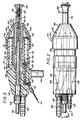
- the powder spraying device 11 mainly consists of the assembly of a metallic body 12 and connected to the earth in the example described containing a certain number of passages and cavities and a pipe 13 for circulating the tubular and cylindrical air-powder mixture, connected sealingly to the body 12 by one of its ends, with the interposition of an annular seal 14.
- the insulating conduit 13 has at its other end an orifice 15 for ejecting said air-powder mixture.
- the body 12 and the circulation duct 13 are crossed by an insulating rod 16, arranged coaxially with the duct 13, with a tubular structure housing a high-voltage cable 17 whose core 17 a is in contact with a spring 18 establishing the electrical connection with one end of a resistor 19.
- a charging electrode 20 comprising a disc-shaped collar 21 coaxial with the rod 16 and the conduit 13 and extending substantially perpendicular to this axis. Its circular outline emerges from the lateral surface of the insulating rod 16. The latter is held in its axial position by being engaged in a bore 22 of the body 12 on the one hand, and in the central bore of a part 24 provided with 'radial fins 26 bearing against the internal wall of the conduit 13, on the other hand.
- the charging electrode 20 is located outside the ejection orifice 15, in the axial extension of the circulation duct 13 of the air-powder mixture.
- the insulating rod is extended in the direction of ejection of the air-powder mixture by an enlarged part 27 forming a deflector.
- the charging electrode 20 is here interposed between the cylindrical rod 16 and the enlarged part 27 and constitutes, by virtue of threaded portions located in the extension of one another, the means of assembly of these two elements.
- the body 12 is provided with a connector 29 by which the air-powder mixture is introduced into an inclined passage 30. The latter communicates with the end of the circulation duct 13, assembled to said body 12.
- Another connector (not visible in the drawing) communicates with holes 31, 32 of the body 12. It is intended to be connected to a source of compressed air.
- the bore 32 opens into an annular housing 34 defined between the external surface of the conduit 13 and a conduit 35, generally cylindrical, attached in a sealed manner to the body 12, by one of its ends, with the interposition of a seal 36.
- the arrangement (31, 32, 34, 35) forms blowing means for cleaning a counter-electrode 38 placed outside the circulation duct 13 so as to close one end of the annular housing 34.
- the counter-electrode is porous, for example made of porous bronze. This feature is known per se.
- pressurized air injected into the annular housing 34 escapes through said counter electrode 38.
- the latter forms a flat annular wall bearing, internally, against a shoulder of the external surface of said circulation conduit 13 and, externally, against one end of the conduit element 35.
- the conduit 13 and the conduit element 35 are made of insulating material and the counter-electrode is brought to a selected potential, in this case the earth potential , by a spring 39 slightly compressed in the annular housing and coming into contact with the body 12.
- the counter-electrode external to the conduit 13 and which extends perpendicular to the axis of the latter is protected by an external sleeve 40 which defines with the circulation conduit 13 and around that here, an elongated annular space 41.
- the latter is therefore located in the extension of the counter electrode in the direction of the charging electrode 20 and, because here the counter electrode is porous, the blowing means defined below above open into this annular space 41.
- the counter-electrode 38 in the form of a flat annular wall, therefore extends between the external surface of the circulation duct and one end of the external sleeve 40.
- the element of conduit 35 and the sleeve 40 are located coaxially in the extension of one another and the counter-electrode 38 is clamped externally between the opposite ends of said conduit element 35 and said sleeve 40.
- a mounting ring 45 internally threaded, is screwed on an external threaded portion of the duct element 35 and it has an internal shoulder 46 at one end, which bears against an external shoulder 47 of the sleeve 40.
- the ring 40 and the sleeve 45 can be produced in one room.
- a metal rod 48 in electrical contact with the charging electrode 20 (and which can advantageously be an extension of the latter) emerges axially from the end of said enlarged part 27. This feature improves the configuration of the deposition field.
- the sleeve 40 is not necessarily cylindrical, it can be conical, widening in the direction of the counter electrode 38, which makes it possible to use a larger counter electrode. If the charging electrode is not brought to a very high high voltage, the counter electrode 38 can be earthed. On the other hand, if one wants to increase the voltage applied to the charging electrode, so as to increase the deposition field, one can avoid modifying the dimensions of the device, that is to say in particular the distance between the electrode load and the counter-electrode, by bringing said counter-electrode to an intermediate voltage. As an example, we try to maintain a difference of potential of 30 kV between the two electrodes.
- the charging electrode can be brought up to 90 kV, the counter-electrode then being brought to 60 kV.
- the charging electrode 20 is not necessarily located at the junction between the cylindrical part of the rod 16 and the enlarged part 27.
- the charging electrode can in particular emerge at any point from said enlarged part and even be constituted by a simple metal disc covering the end of the deflector, the rod 48 then being removed. It is also possible to envisage making the charging electrode in the form of several points, for example three, regularly distributed angularly and projecting preferably at the periphery of the deflector.
- the counter electrode can be formed from another porous metal (for example porous stainless steel) or from a conductive synthetic material. Nor does it have to be porous; one could perfectly conceive a variant in which air passages would bypass it to establish air circulation between the housing 34 and the annular space 41.
- the rear body 112 equipped with a support foot 110 is made in this case of insulating material. It is provided with the connector 129 by which the air-powder mixture is introduced into the inclined and flared passage 130 opening into the circulation duct 113. Another connection 131 connected to a source of compressed air gives access to a bore 132 which opens out. in the annular housing 134 defined between the external surface of the circulation conduit 113 and the external conduit element 135. There is at 138 the counter-electrode, for example made of porous bronze, which closes the anterior end of the annular passage 134. This counter-electrode is kept at ground potential by means of the spring 139 which here finds support on the rear body 112, by means of a conductive stud 150, itself connected to a connection terminal. the earth 151, by means of a spring 152 extending in a pipe 153 formed for this purpose in the body 112.
- the counter-electrode 138 is held in abutment against bearing surfaces provided for this purpose on the circulation duct 113, on the one hand, and at the end of the outer duct 134, on the other hand, by means of a sleeve or skirt 140 Coming in one piece with a skirt nut 145.
- the skirt sleeve 140 has a tapered frustoconical shape achieving a significant reduction in the section of the annular space 141.
- the frustoconical wall of the sleeve-skirt 140 is pierced with a circular row of holes 142 uniformly distributed over the periphery, opposite the counter-electrode 138.
- the circulation duct 113 has, for its part, a very tapered end portion 113A with a wall external of frustoconical shape, the generator of this truncated cone forming with the axial direction an acute angle of small value, for example of about 5 °.
- the frustoconical skirt sleeve 140 comprises, for its part, a tapered end portion delimited on the radially inner side by a frustoconical wall 143 substantially parallel to the frustoconical end surface 113A, so as to establish with the latter an annular passage of reduced cross section constituting a kind of exhaust nozzle T for the annular space 141.
- the protection against unwanted capture of charged particles is due to the accelerated flow velocities through the nozzle T in the axial direction where the electrostatic driving forces are highest. Protection is also ensured with regard to the risks of particles rising through the holes and the air exhaust speeds are lower, but so are the electrostatic driving forces.
- the drilling diameter of the holes 142 will generally be between 1 and 4 mm. Excellent results have been obtained with a prototype provided with twelve holes of 3 mm in diameter, thus offering a total passage surface of approximately 85 mm 2, while the passage section offered by the nozzle T with an average diameter of 22 mm and a thickness of 2.5 mm was roughly equivalent.
- the very tapered shape of the end portion 113 of the air-powder mixture circulation duct very effectively avoids the risks of powder accumulation and the projection of agglomerates.
Description
L'invention se rapporte à un dispositif de projection électrostatique de produit en poudre et plus particulièrement un produit de revêtement véhiculé par de l'air, l'invention vise plus particulièrement un perfectionnement permettant d'éviter qu'une contre-électrode (dont le rôle est, notamment, de capter les ions libres du mélange air-poudre éjecté vers un objet à recouvrir), ne perde progressivement son efficacité en étant recouverte par le produit de revêtement formant une pellicule isolante.The invention relates to a device for electrostatic projection of powdered product and more particularly a coating product conveyed by air, the invention relates more particularly to an improvement making it possible to avoid that a counter-electrode (including the role is, in particular, to capture the free ions of the air-powder mixture ejected towards an object to be covered), does not gradually lose its effectiveness by being covered by the coating product forming an insulating film.
Le poudrage électrostatique est couramment utilisé dans l'industrie, notamment pour recouvrir des objets d'une peinture thermofusible appliquée en poudre. Lorsque de tels objets sont entièrement recouverts d'une couche suffisante de poudre, ils sont acheminés vers un four où le revêtement pulvérulent se transforme en une couche de peinture homogène et résistante, par fusion des grains de poudre entre eux suivie en général d'une polymérisation.Electrostatic powdering is commonly used in industry, in particular to cover objects with a hot-melt paint applied in powder. When such objects are completely covered with a sufficient layer of powder, they are transported to an oven where the powder coating becomes a homogeneous and resistant layer of paint, by melting the grains of powder together followed in general by a polymerization.
Pour charger électriquement les particules de poudre du mélange air-poudre, on peut créer un champ électrique de charge entre une électrode de charge placée dans le mélange air-poudre et une contre-électrode séparée de l'électrode de charge par une distance de quelques centimètres. Il est nécessaire, aussi, de créer un champ de dépôt entre le dispositif de projection et l'objet à recouvrir. Ceci est généralement obtenu en portant l'électrode de charge à une haute tension électrique et en reliant l'objet à la terre. La contre-électrode peut elle-même reliée à la terre ou portée à un potentiel intermédiaire, pour créer le champ voulu, compte tenu des dimensions du projecteur et notamment de la distance entre les deux électrodes.To electrically charge the powder particles of the air-powder mixture, an electric charge field can be created between a charging electrode placed in the air-powder mixture and a counter electrode separated from the charging electrode by a distance of a few centimeters. It is also necessary to create a deposit field between the projection device and the object to be covered. This is generally achieved by bringing the charging electrode to a high electrical voltage and connecting the object to earth. The counter-electrode can itself be connected to earth or brought to an intermediate potential, to create the desired field, taking into account the dimensions of the projector and in particular the distance between the two electrodes.
De ce point de vue, on cherche à mettre au point des dispositifs mettant en oeuvre des tensions qui ne soient pas exagérément élevées. Il est souhaitable en particulier de créer un champ de charge sur une distance de 30 à 40 mm avec une différence de potentiel de l'ordre de 30 kV entre les électrodes.From this point of view, it is sought to develop devices implementing voltages which are not excessively high. It is particularly desirable to create a charge field over a distance of 30 to 40 mm with a potential difference of around 30 kV between the electrodes.
On a constaté que, si des ions libres se propageaient en même temps que le mélange air-poudre vers l'objet à recouvrir, en étant entraînés par le champ de dépôt, des différences de concentration de dépôt de poudre pouvaient se produire entre les reliefs et les enfractuosités de l'objet. Ces différences de concentration de poudre sont bien évidemment à l'origine de différences d'épaisseur dans la couche de peinture, après passage au four. Il est donc souhaitable que, sensiblement tous les ions libres qui n'ont pas pu charger la poudre soient récupérés par un piège à ions, en l'occurrence la contre-électrode. Plusieurs configurations de contre-électrode ont été proposées pour assurer au mieux la "récupération" des ions libres. Beaucoup de solutions proposées placent la contre-électrode à l'intérieur du conduit de circulation du mélange air-poudre ou en communication directe avec l'intérieur de ce conduit. Ces solutions sont généralement peu satisfaisantes en raison du fait que la poudre vient plus ou moins rapidement recouvrir la contre-électrode aboutissant à la formation d'un revêtement isolant l'empêchant de jouer son rôle de piège à ions. On suppose que l'un des phénomènes en cause est une fusion locale des grains de poudre résultant de leur énergie d'impact sur la contre-électrode. Pour éviter une telle agglomération de poudre sur la contre-électrode, on a proposé de la nettoyer en permanence par une circulation d'air propre et même de prévoir une contre-électrode poreuse traversée en permanence par de l'air. Une solution de ce type est par exemple décrite dans le brevet français N° 2 283 729. On a aussi proposé de placer l'électrode à l'extérieur du conduit de circulation du mélange air-poudre mais on n'a pas pu, jusqu'à présent, empêcher que des particules de poudre entraînées par des tourbillons ne viennent recouvrir la contre-électrode. Dans cet ordre d'idée, le brevet américain N° 4 228 961 propose une structure à contre-électrode cylindrique axiale, nettoyée par un jet d'air entretenu dans un très faible espace annulaire autour de la contre-électrode. Le nettoyage permanent de la contre-électrode par ce jet d'air n'a pas donné de bons résultats et on peut attribuer cet échec au fait que le jet d'air peut favoriser lui-même la formation de tourbillons au voisinage de la contre-électrode. De plus, il semble que la forme de cette contre-électrode et la faible section du passage que doivent emprunter les ions libres pour venir rencontrer la contre-électrode, réduisent considérablement l'efficacité de cette dernière en tant que piège à ions. En outre, un passage d'aussi faible section peut s'obturer en utilisation.It was found that, if free ions propagated at the same time as the air-powder mixture towards the object to be covered, by being entrained by the deposition field, differences in concentration of powder deposition could occur between the reliefs and the object's fractures. These differences in powder concentration are obviously the source of differences in thickness in the paint layer, after passing through the oven. It is therefore desirable that substantially all of the free ions which could not charge the powder are recovered by an ion trap, in this case the counter-electrode. Several counter-electrode configurations have been proposed to best ensure the "recovery" of free ions. Many of the solutions proposed place the counter-electrode inside the air-powder mixture circulation conduit or in direct communication with the interior of this conduit. These solutions are generally unsatisfactory due to the fact that the powder comes more or less quickly to cover the counter-electrode, leading to the formation of an insulating coating preventing it from playing its role of ion trap. It is assumed that one of the phenomena in question is a local fusion of the powder grains resulting from their impact energy on the counter-electrode. To avoid such agglomeration of powder on the counter-electrode, it has been proposed to clean it permanently by a circulation of clean air and even to provide a porous counter-electrode permanently traversed by air. A solution of this type is for example described in French patent No. 2 283 729. It has also been proposed to place the electrode outside the air-powder mixture circulation duct, but it has not been possible, until 'Now prevent particles of powder entrained by vortices from covering the counter electrode. In this connection, the American patent N ° 4 228 961 proposes a structure with an axial cylindrical counter-electrode, cleaned by an air jet maintained in a very small annular space around the counter-electrode. The permanent cleaning of the counter electrode by this air jet has not given good results and this failure can be attributed to the fact that the air jet can itself promote the formation of vortices in the vicinity of the counter -electrode. In addition, it seems that the shape of this counter-electrode and the small cross-section of the passage which the free ions must take to come and meet the counter-electrode, considerably reduce the effectiveness of the latter as an ion trap. In addition, a passage of such a small section can be closed in use.
L'invention propose un nouvel agencement de dispositif de projection électrostatique de poudre, comportant une contre-électrode située à l'extérieur du conduit de circulation, de forme et dimensions propres à lui permettre de jouer efficacement son rôle de piège à ions, ladite contre-électrode étant associée à des moyens de soufflage assurant, entre autre, son nettoyage permanent. L'invention vise notamment un agencement permettant d'éviter que des tourbillons de mélange air-poudre ne se forment au voisinage immédiat de la contre-électrode, notamment en raison de l'écoulement même de l'air chargé de nettoyer cette contre-électrode.The invention provides a new arrangement of an electrostatic powder projection device, comprising a counter-electrode situated outside the circulation duct, of a shape and dimensions suitable for enabling it to effectively play its role of ion trap, said counter -electrode being associated with blowing means ensuring, among other things, its permanent cleaning. The invention relates in particular to an arrangement making it possible to prevent vortices of air-powder mixture from forming in the immediate vicinity of the counter electrode, in particular due to the very flow of the air responsible for cleaning this counter electrode .
Dans cet esprit, l'invention concerne donc un dispositif de projection électrostatique de produit en poudre, notamment un produit de revêtement, du type comportant un conduit de circulation d'un mélange air-poudre, muni d'un orifice d'éjection à une extrémité, une électrode de charge disposée au voisinage dudit orifice d'éjection et une contre-électrode agencée coaxialement à ladite électrode de charge dans un espace annulaire allongé ouvert, coaxial audit conduit de circulation et en retrait axialement par rapport à l'orifice d'éjection de ce dernier, cet espace annulaire étant relié à des moyens de soufflage d'air et une différence de potentiel étant appliquée entre les deux électrodes pour créer un champ électrique susceptible d'entraîner des ions libres vers ladite contre-électrode, caractérisé en ce que ladite contre-électrode est située au fond dudit espace annulaire par rapport à son ouverture et s'étend sensiblement perpendiculairement à l'axe de ce dernier et en ce que lesdits moyens de soufflage d'air débouchent dans ledit espace annulaire au voisinage de ladite contre-électrode.In this spirit, the invention therefore relates to a device for electrostatic projection of powdered product, in particular a coating product, of the type comprising a duct for circulating an air-powder mixture, provided with an ejection orifice at a end, a charging electrode disposed in the vicinity of said ejection orifice and a counter electrode arranged coaxially with said charging electrode in an open elongated annular space, coaxial with said circulation conduit and axially withdrawn from the orifice ejection of the latter, this annular space being connected to air blowing means and a potential difference being applied between the two electrodes to create an electric field capable of causing free ions towards said counter-electrode, characterized in that said counter-electrode is situated at the bottom of said annular space with respect to its opening and extends substantially perpendicular to the axis of the latter and in that said air blowing means open into said annular space in the vicinity of said counter-electrode.
De façon simple, l'espace annulaire précité est défini entre la surface externe dudit conduit de circulation du mélange air-poudre et un manchon extérieur et coaxial à ce conduit.In a simple manner, the abovementioned annular space is defined between the external surface of said conduit for circulation of the air-powder mixture and an outer sleeve and coaxial with this conduit.
Ainsi, la contre-électrode peut, sans inconvénient, présenter une surface annulaire (perpendiculaire à l'axe du dispositif) relativement importante et disposée de telle sorte que les ions libres subsistant dans l'espace où règne le champ de charge, soient en quasi-totalité attirés vers elle. Du fait que l'air se trouve canalisé dans ledit espace annulaire, relativement long, les particules de poudre qui pourraient être attirées vers la contre-électrode du fait de leur charge, sont repoussées par la force du jet d'air. Le rôle de ce dernier n'est donc plus seulement de nettoyer la contre-électrode, mais aussi, d'empêcher que des grains de poudre ne l'atteignent. De plus, des tourbillons susceptibles de transporter de la poudre vers la contre-électrode ne sont plus à craindre puisqu'aucun appel d'air ambiant pollué n'est possible au voisinage de celle-ci.Thus, the counter-electrode can, without drawback, have a relatively large annular surface (perpendicular to the axis of the device) and arranged so that the free ions remaining in the space where the charge field prevails, are almost - all attracted to it. Because the air is channeled into said relatively long annular space, the powder particles which could be attracted to the counter-electrode due to their charge, are repelled by the force of the air jet. The latter's role is therefore no longer only to clean the counter-electrode, but also to prevent grains of powder from reaching it. In addition, eddies capable of transporting powder to the counter-electrode are no longer to be feared since no call for polluted ambient air is possible in the vicinity thereof.
L'invention concerne aussi une forme particulière de réalisation d'un tel aménagement qui procure une amélioration surprenante des performances du dispositif.The invention also relates to a particular embodiment of such an arrangement which provides a surprising improvement in the performance of the device.
Un premier moyen de cette variante consiste en une configuration effilée, en particulier tronconique, du manchon de confinement de l'espace annulaire formé devant la contre-électrode: il en résulte une réduction avantageuse intéressante de la consommation d'air et une meilleure pénétration du revêtement sur les pièces présentant des cavités.A first means of this variant consists of a tapered configuration, in particular frustoconical, of the sleeve for confining the annular space formed in front of the counter-electrode: this results in an advantageous advantageous reduction in air consumption and better penetration of the coating on parts with cavities.
Selon une autre disposition de cette variante le manchon de confinement précité est percé d'une pluralité d'orifices débouchant à proximité de la contre-électrode: ces orifices créent pour l'air de balayage de la contre-électrode des voies d'échappement selon une pluralité de directions transversales par rapport à la direction de projection. Ces voies d'échappement de l'air de balayage constituent un moyen d'amélioration de l'efficacité de la contre-électrode dans son action de piège à ions en vue du captage sélectif des ions libres dans le mélange air-poudre éjecté vers l'objet à recouvrir.According to another arrangement of this variant, the abovementioned confining sleeve is pierced with a plurality of orifices opening out near the counter-electrode: these orifices create exhaust paths for the counter-electrode scanning air according to a plurality of directions transverse to the direction of projection. These scavenging air escape channels constitute a means of improving the efficiency of the counter-electrode in its ion trap action with a view to the selective capture of free ions in the air-powder mixture ejected towards the object to be covered.
Selon une autre disposition de la variante, on donne à la partie terminale du conduit de mélange air-poudre une forme très effilée avec comme avantage d'éviter pratiquement tout risque d'accumulation de poudre à l'orifice d'éjection ce qui est une source d'amélioration de la qualité du revêtement obtenu grâce à la réduction du risque de projection d'agglomérats.According to another arrangement of the variant, the terminal part of the air-powder mixing duct is given a very tapered shape with the advantage of avoiding practically any risk of accumulation of powder at the ejection orifice which is a source of improvement in the quality of the coating obtained by reducing the risk of projection of agglomerates.
L'invention sera mieux comprise et d'autres avantages de celle-ci apparaîtront plus clairement à la lumière de la description qui va suivre d'un mode de réalisation conforme à son principe, donnée uniquement à titre d'exemple et faite en référence aux dessins annexés dans lesquels:
- _ la figure 1 est une vue schématique en coupe longitudinale d'un mode de réalisation possible d'un dispositif de projection électrostatique de poudre conforme à l'invention;
- _ la figure 2 est une vue en plan d'un autre dispositif de projection conforme à l'invention; et
- _ la figure 3 est une vue en coupe longitudinale selon le plan III-III de la figure 2.
- _ Figure 1 is a schematic view in longitudinal section of a possible embodiment of an electrostatic powder spraying device according to the invention;
- _ Figure 2 is a plan view of another projection device according to the invention; and
- _ Figure 3 is a longitudinal sectional view along the plane III-III of Figure 2.
Le dispositif de projection de poudre 11, tel que représenté à la figure 1, se compose principalement de l'assemblage d'un corps 12 métallique et relié à la terre dans l'exemple décrit renfermant un certain nombre de passages et cavités et d'un conduit de circulation 13 du mélange air-poudre tubulaire et cylindrique, raccordé de façon étanche au corps 12 par l'une de ses extrémités, avec interposition d'un joint annulaire 14. Le conduit 13 isolant, comporte à son autre extrémité, un orifice d'éjection 15 dudit mélange air-poudre. Le corps 12 et le conduit de circulation 13 sont traversés par une tige isolante 16, disposée coaxialement au conduit 13, à structure tubulaire abritant un câble haute-tension 17 dont l'âme 17a est en contact avec un ressort 18 établissant la liaison électrique avec une extrémité d'une résistance 19. L'autre extrémité de cette résistance est en contact avec une électrode de charge 20 comportant une collerette en forme de disque 21 coaxiale à la tige 16 et au conduit 13 et s'étendant sensiblement perpendiculairement à cet axe. Son contour circulaire émerge de la surface latérale de la tige isolante 16. Cette dernière est maintenue dans sa position axiale en étant engagée dans un alésage 22 du corps 12 d'une part, et dans l'alésage central d'une pièce 24 munie d'ailettes radiales 26 en appui contre la paroi interne du conduit 13, d'autre part. L'électrode de charge 20 est située à l'extérieur de l'orifice d'éjection 15, dans le prolongement axial du conduit de circulation 13 du mélange air-poudre. De façon connue en soi, la tige isolante est prolongée dans la direction d'éjection du mélange air-poudre par une partie élargie 27 formant déflecteur. L'électrode de charge 20 est ici interposée entre la tige cylindrique 16 et la partie élargie 27 et constitue, grâce à des portions filetées situées dans le prolongement l'une de l'autre, le moyen d'assemblage de ces deux éléments. Le corps 12 est muni d'un raccord 29 par lequel le mélange air-poudre est introduit dans un passage incliné 30. Ce dernier communique avec l'extrémité du conduit de circulation 13, assemblée audit corps 12.The
Un autre raccord (non visible sur le dessin) communique avec des perçages 31, 32 du corps 12. Il est prévu pour être connecté à une source d'air comprimé. Le perçage 32 débouche dans un logement annulaire 34 défini entre la surface externe du conduit 13 et un élément de conduit 35, globalement cylindrique, rapporté de façon étanche au corps 12, par l'une de ses extrémités, avec interposition d'un joint 36. L'agencement (31, 32, 34, 35) forme des moyens de soufflage pour le nettoyage d'une contre-électrode 38 placée à l'extérieur du conduit de circulation 13 de façon à obturer une extrémité du logement annulaire 34. Dans le dispositif décrit, la contre-électrode est poreuse, par exemple en bronze poreux. Cette particularité est connue en soi. Ainsi, de l'air sous pression injecté dans le logement annulaire 34 s'échappe au travers de ladite contre-électrode 38. Cette dernière forme une paroi annulaire plate prenant appui, intérieurement, contre un épaulement de la surface externe dudit conduit de circulation 13 et, extérieurement, contre une extrémité de l'élément de conduit 35. Le conduit 13 et l'élément de conduit 35 sont en matériau isolant et la contre-électrode est portée à un potentiel choisi, dans le cas présent le potentiel de la terre, par un ressort 39 légèrement comprimé dans le logement annulaire et venant au contact du corps 12.Another connector (not visible in the drawing) communicates with
Selon une caractéristique importante de l'invention, la contre-électrode, extérieure au conduit 13 et qui s'étend perpendiculairement à l'axe de ce dernier est protégée par un manchon extérieur 40 qui définit avec le conduit de circulation 13 et autour de celui-ci, un espace annulaire allongé 41. Ce dernier se situe donc dans le prolongement de la contre-électrode en direction de l'électrode de charge 20 et, du fait ici que la contre-électrode est poreuse, les moyens de soufflage définis ci-dessus débouchent dans cet espace annulaire 41. La contre-électrode 38, en forme de paroi annulaire plate, s'étend donc entre la surface externe du conduit de circulation et une extrémité du manchon extérieur 40. Pour faciliter le montage, l'élément de conduit 35 et le manchon 40 sont situés coaxialement dans le prolongement l'un de l'autre et la contre-électrode 38 est serrée extérieurement entre les extrémités en regard dudit élément de conduit 35 et dudit manchon 40. Pour ce faire, une bague de montage 45, filetée intérieurement, est vissée sur une portion filetée externe de l'élément de conduit 35 et elle comporte un épaulement interne 46 à une extrémité, lequel prend appui contre un épaulement externe 47 du manchon 40. Avantageusement, la bague 40 et le manchon 45 peuvent être réalisés en une seule pièce.According to an important characteristic of the invention, the counter-electrode, external to the
On a constaté qu'avec cet agencement, la force communiquée par l'air circulant dans le manchon 40 aux particules chargées (cette force dépend essentiellement de la vitesse de l'écoulement de l'air dans le manchon et de la surface des particules) était supérieure à la force d'origine électrique attirant ces mêmes particules chargées. Ces conditions ne sont réalisées qu'en présence du manchon en raison de la canalisation de l'air s'échappant de la contre-électrode. Par ailleurs, aucun tourbillon (susceptible d'entraîner de la poudre) ne peut se former au voisinage de la contre-électrode, les zones tourbillonnaires étant, au pire, reportées vers l'avant, au voisinage de l'extrémité du manchon 40.It has been found that with this arrangement, the force imparted by the air flowing in the
Une tige métallique 48, en contact électrique avec l'électrode de charge 20 (et pouvant avantageusement être un prolongement de celle-ci) émerge axialement de l'extrémité de ladite partie élargie 27. Cette particularité améliore la configuration du champ de dépôt.A metal rod 48, in electrical contact with the charging electrode 20 (and which can advantageously be an extension of the latter) emerges axially from the end of said
Bien entendu, l'invention n'est pas limitée au mode de réalisation qui vient d'être décrit. Le manchon 40 n'est pas obligatoirement cylindrique, il peut être conique, en s'élargissant en direction de la contre-électrode 38, ce qui permet d'utiliser une contre-électrode plus grande. Si l'électrode de charge n'est pas portée à une haute-tension très élevée, la contre-électrode 38 peut être reliée à la terre. En revanche, si on veut augmenter la tension appliquée à l'électrode de charge, de façon à augmenter le champ de dépôt, on peut éviter de modifier les dimensions du dispositif, c'est-à-dire notamment la distance entre l'électrode de charge et la contre-électrode, en portant ladite contre-électrode à une tension intermédiaire. A titre d'exemple, on cherche à maintenir une différence de potentiel de 30 kV entre les deux électrodes. Si on désire augmenter le champ de dépôt, on peut porter l'électrode de charge jusqu'à 90 kV, la contre-électrode étant alors portée à 60 kV. D'autres modifications sont possibles. En particulier, l'électrode de charge 20 n'est pas obligatoirement située à la jonction entre la partie cylindrique de la tige 16 et la partie élargie 27. L'électrode de charge peut notamment émerger en n'importe quel point de ladite partie élargie et même être constituée par un simple disque métallique recouvrant l'extrémité du déflecteur, la tige 48 étant alors supprimée. On peut encore envisager de réaliser l'électrode de charge sous forme de plusieurs pointes, par exemple trois, régulièrement réparties angulairement et faisant saillie de préférence à la périphérie du déflecteur. Enfin, la contre-électrode peut être formée dans un autre métal poreux (par exemple de l'acier inoxydable poreux) ou dans un matériau synthétique conducteur. Il n'est pas non plus indispensable qu'elle soit poreuse; on pourrait parfaitement concevoir une variante dans laquelle des passages d'air la contourneraient pour établir une circulation d'air entre le logement 34 et l'espace annulaire 41.Of course, the invention is not limited to the embodiment which has just been described. The
On reconnaît dans l'exemple de réalisation des figures 2 et 3, la plupart des éléments du dispositif décrit en référence à la figure 1, les éléments semblables étant désignés par les mêmes références augmentées de 100.In the embodiment of FIGS. 2 and 3, most of the elements of the device described with reference to FIG. 1 are recognized, the similar elements being designated by the same references increased by 100.
On retrouve donc, pour constituer le dispositif de projection de poudre 111, l'assemblage d'un corps arrière 112 avec un conduit de circulation 113 de mélange air-poudre aboutissant à un orifice d'éjection 115. On retrouve une tige isolante 116 traversant le corps 112 et le conduit 113 avec le câble de haute tension 117 dont l'âme est placée par le ressort 118 en liaison électrique avec une résistance 119, elle-même en contact avec l'électrode de charge 120 comportant la collerette 121, en arrière de la partie terminale évasée 127, formant déflecteur.So to find the
Il convient de noter que le dépassement en sens radial de la collerette 121 par rapport à la surface périphérique de la tige isolante 116 et de son prolongement 127, est limité à la valeur juste suffisante pour la formation d'effluves. Ce dépassement est de l'ordre du dixième de millimètre.It should be noted that the overshoot in direction radial of the
Le corps arrière 112 équipé d'un pied support 110 est réalisé dans le cas présent en matériau isolant. Il est muni du raccord 129 par lequel le mélange air-poudre est introduit dans le passage incliné et évasé 130 débouchant dans le conduit de circulation 113. Un autre raccord 131 relié à une source d'air comprimé donne accès à un perçage 132 qui débouche dans le logement annulaire 134 défini entre la surface externe du conduit de circulation 113 et l'élément de conduit extérieur 135. On retrouve en 138 la contre-électrode, par exemple en bronze poreux, qui obture l'extrémité antérieure du passage annulaire 134. Cette contre-électrode est maintenue au potentiel à la terre par l'intermédiaire du ressort 139 qui trouve ici un appui sur le corps arrière 112, par l'intermédiaire d'un plot conducteur 150, lui-même connecté à une cosse de mise à la terre 151, par l'intermédiaire d'un ressort 152 s'étendant dans une canalisation 153 ménagée à cet effet dans le corps 112.The
La contre-électrode 138 est maintenue en butée contre des portées ménagées à cet effet sur le conduit de circulation 113, d'une part, et en bout du conduit extérieur 134, d'autre part, au moyen d'un manchon ou jupe 140 venu d'une seule pièce avec un écrou de jupe 145. Selon une caractéristique importante de ce mode de réalisation, le manchon-jupe 140 présente une forme tronconique effilée réalisant une réduction notable de la section de l'espace annulaire 141. La paroi tronconique du manchon-jupe 140 est percée d'une rangée circulaire de trous 142 uniformément répartis sur la périphérie, en regard de la contre-électrode 138.The counter-electrode 138 is held in abutment against bearing surfaces provided for this purpose on the
Le conduit de circulation 113 présente, de son côté, une partie terminale 113A très effilée avec une paroi externe de forme tronconique, la génératrice de ce tronc de cône formant avec la direction axiale un angle aigu de faible valeur, par exemple d'environ 5°.The
Le manchon-jupe tronconique 140 comporte, de son côté, une partie terminale effilée délimitée du côté radialement intérieur par une paroi tronconique 143 sensiblement parallèle à la surface terminale tronconique 113A, de manière à établir avec celle-ci un passage annulaire de section réduite constituant une sorte de tuyère d'échappement T pour l'espace annulaire 141.The
L'espace annulaire 141 confiné par le manchon-jupe 140 devant la contre-électrode 138 autour du conduit 113 de circulation du mélange offre donc à l'air de soufflage ayant franchi la contre-électrode la possibilité de s'échapper par deux voies différentes:
- la voie axiale pour laquelle la section de passage est fortement réduite et la vitesse d'écoulement accélérée dans la tuyère d'échappement T;
- la voie radiale constituée par la série de trous 142 dont la présence a pour effet de réduire la pression susceptible de s'établir devant la contre-électrode en offrant une multiplicité de voies d'échappement à des vitesses d'écoulement qui seront naturellement fonction du diamètre de perçage des trous.
- the axial channel for which the passage section is greatly reduced and the flow speed accelerated in the exhaust nozzle T;
- the radial channel formed by the series of
holes 142 whose presence has the effect of reducing the pressure likely to be established in front of the counter-electrode by offering a multiplicity of exhaust channels at flow rates which will naturally depend on the hole drilling diameter.
L'expérience montre que cet agencement permet une amélioration considérable des performances du dispositif de projection et ceci pour de multiples raisons dont les effets se combinent entre eux de manière particulièrement opportune et avantageuse.Experience shows that this arrangement allows a considerable improvement in the performance of the projection device, for a number of reasons, the effects of which combine with one another in a particularly timely and advantageous manner.
On constate, en premier lieu, une amélioration extrêmement sensible de la qualité du revêtement obtenu, en particulier sur des pièces présentant des cavités grâce à une réduction du risque de réentraînement des particules parvenues sur la pièce par l'air de soufflage provenant de la contre-électrode.There is, firstly, an extremely significant improvement in the quality of the coating obtained, in particular on parts having cavities thanks to a reduction in the risk of re-entrainment of the particles reached on the part by the blowing air coming from the counter -electrode.
En effet, toutes choses égales par ailleurs, une partie notable de cet air de soufflage s'échappe latéralement par la voie radiale offerte par les trous 142, ce qui diminue d'autant la quantité d'air s'échappant en direction de la pièce par la tuyère axiale T.All other things being equal, a significant part of this blowing air escapes laterally by the radial path offered by the
On bénéficie en second lieu globalement d'une réduction de la consommation d'air.Secondly, there is generally a reduction in air consumption.
En troisième lieu, on constate une amélioration surprenante de l'efficacité de la contre-électrode en tant que piège à l'égard des ions libres, avec une réduction de la probabilité du captage indésirable des particules chargées.Third, there is a surprising improvement in the efficiency of the counter electrode as a trap for free ions, with a reduction in the probability of unwanted capture of charged particles.
Ce captage efficace et régulier des ions libres se traduit notamment par l'établissement d'un courant important et stable, par exemple de 30 microampères entre électrode et contre-électrode, ce qui semble être principalement attribuable aux faisceaux de lignes de force et d'écoulement susceptibles de traverser les trous 142.This efficient and regular collection of free ions results in particular in the establishment of a large and stable current, for example of 30 microamps between electrode and counter-electrode, which seems to be mainly attributable to beams of force lines and flow likely to pass through holes 142.
La protection contre le captage indésirable des particules chargée est attribuable aux vitesses d'écoulement accélérées à travers la tuyère T dans le sens axial où les forces d'entraînement électrostatiques sont les plus élevées. La protection est également assurée à l'égard des risques de remontée des particules à travers les trous et les vitesses d'échappement de l'air sont plus faibles mais les forces électrostatiques d'entraînement le sont aussi.The protection against unwanted capture of charged particles is due to the accelerated flow velocities through the nozzle T in the axial direction where the electrostatic driving forces are highest. Protection is also ensured with regard to the risks of particles rising through the holes and the air exhaust speeds are lower, but so are the electrostatic driving forces.
Le diamètre de perçage des trous 142 sera en général compris entre 1 et 4 mm. On a obtenu d'excellents résultats avec un prototype muni de douze trous de 3 mm de diamètre, offrant donc une surface totale de passage d'environ 85 mm2, alors que la section de passage offerte par la tuyère T avec un diamètre moyen de 22 mm et une épaisseur de 2,5 mm était sensiblement équivalente.The drilling diameter of the
La forme très effilée de la partie terminale 113 du conduit de circulation du mélange air-poudre évite très efficacement les risques d'accumulation de poudre et la projection d'agglomérats. Interviennent à cet égard de manière également avantageuse la forme également effilée de la partie terminale 143 du manchon-jupe 140 et la continuité de ce dernier avec l'écrou de jupe 145.The very tapered shape of the
Claims (21)
Applications Claiming Priority (4)
| Application Number | Priority Date | Filing Date | Title |
|---|---|---|---|
| FR8701765 | 1987-02-12 | ||
| FR8701765A FR2610849B1 (en) | 1987-02-12 | 1987-02-12 | ELECTROSTATIC PROJECTION OF POWDERED PRODUCT |
| FR8712765 | 1987-09-15 | ||
| FR878712765A FR2620354B2 (en) | 1987-02-12 | 1987-09-15 | DEVICE FOR ELECTROSTATIC PROJECTION OF POWDERED PRODUCT |
Publications (2)
| Publication Number | Publication Date |
|---|---|
| EP0281438A1 EP0281438A1 (en) | 1988-09-07 |
| EP0281438B1 true EP0281438B1 (en) | 1991-04-17 |
Family
ID=26225773
Family Applications (1)
| Application Number | Title | Priority Date | Filing Date |
|---|---|---|---|
| EP88400223A Expired - Lifetime EP0281438B1 (en) | 1987-02-12 | 1988-02-01 | Device for the electrostatic spraying of powdery products |
Country Status (7)
| Country | Link |
|---|---|
| US (1) | US4921172A (en) |
| EP (1) | EP0281438B1 (en) |
| JP (1) | JP2609659B2 (en) |
| CA (1) | CA1298966C (en) |
| DE (1) | DE3862403D1 (en) |
| ES (1) | ES2021843B3 (en) |
| FR (1) | FR2620354B2 (en) |
Families Citing this family (33)
| Publication number | Priority date | Publication date | Assignee | Title |
|---|---|---|---|---|
| FR2692173B1 (en) * | 1992-06-10 | 1994-09-02 | Sames Sa | Device for electrostatic projection of a powder coating product with a rotating ionization head. |
| US5520735A (en) * | 1992-06-30 | 1996-05-28 | Nordson Corporation | Nozzle assembly and system for applying powder to a workpiece |
| US5344082A (en) * | 1992-10-05 | 1994-09-06 | Nordson Corporation | Tribo-electric powder spray gun |
| US5320283A (en) * | 1993-01-28 | 1994-06-14 | Nordson Corporation | Robot mounted twin headed adjustable powder coating system with spray pattern direction control |
| DE4312262A1 (en) * | 1993-04-15 | 1994-10-20 | Gema Volstatic Ag | Electrostatic spray device |
| DE4325911A1 (en) * | 1993-08-02 | 1995-02-09 | Gema Volstatic Ag | Electrostatic powder spraying device |
| KR960007018A (en) * | 1994-08-17 | 1996-03-22 | 이마무라 가즈스께 | Electrostatic powder coating method and apparatus |
| JPH08332416A (en) * | 1995-06-01 | 1996-12-17 | Nordson Corp | Spray gun fixing assembly equipped with probe for anti-back ionization |
| DE19528398A1 (en) * | 1995-08-02 | 1997-02-06 | Gema Volstatic Ag | Electrostatic spraying device for coating material |
| JPH10314624A (en) * | 1997-05-14 | 1998-12-02 | Nippon Parkerizing Co Ltd | Electrostatic powder coating gun |
| US5850976A (en) * | 1997-10-23 | 1998-12-22 | The Eastwood Company | Powder coating application gun and method for using the same |
| US5908162A (en) * | 1998-02-25 | 1999-06-01 | Nordson Corporation | Spray gun having an anti-back-ionization probe with a control system therefor |
| US5938126A (en) * | 1998-03-23 | 1999-08-17 | Nordson Corporation | Spray gun having a current monitored anti-back-ionization probe |
| US6676049B2 (en) | 2001-11-16 | 2004-01-13 | Efc Systems, Inc. | Bell cup powder spray applicator |
| US6889921B2 (en) * | 2002-09-30 | 2005-05-10 | Illinois Tool Works Inc. | Bell cup skirt |
| US20050023385A1 (en) * | 2003-07-29 | 2005-02-03 | Kui-Chiu Kwok | Powder robot gun |
| US7128277B2 (en) * | 2003-07-29 | 2006-10-31 | Illinois Tool Works Inc. | Powder bell with secondary charging electrode |
| US20050056212A1 (en) * | 2003-09-15 | 2005-03-17 | Schaupp John F. | Split shroud for coating dispensing equipment |
| US20050173556A1 (en) * | 2004-02-09 | 2005-08-11 | Kui-Chiu Kwok | Coating dispensing nozzle |
| JP4656051B2 (en) * | 2006-12-15 | 2011-03-23 | パナソニック電工株式会社 | Electrostatic atomizer |
| US8371517B2 (en) | 2007-06-29 | 2013-02-12 | Illinois Tool Works Inc. | Powder gun deflector |
| US20090020626A1 (en) * | 2007-07-16 | 2009-01-22 | Illinois Tool Works Inc. | Shaping air and bell cup combination |
| US8770496B2 (en) | 2008-03-10 | 2014-07-08 | Finishing Brands Holdings Inc. | Circuit for displaying the relative voltage at the output electrode of an electrostatically aided coating material atomizer |
| US7988075B2 (en) | 2008-03-10 | 2011-08-02 | Illinois Tool Works Inc. | Circuit board configuration for air-powered electrostatically aided coating material atomizer |
| US8496194B2 (en) | 2008-03-10 | 2013-07-30 | Finishing Brands Holdings Inc. | Method and apparatus for retaining highly torqued fittings in molded resin or polymer housing |
| USD608858S1 (en) | 2008-03-10 | 2010-01-26 | Illinois Tool Works Inc. | Coating material dispensing device |
| US8016213B2 (en) | 2008-03-10 | 2011-09-13 | Illinois Tool Works Inc. | Controlling temperature in air-powered electrostatically aided coating material atomizer |
| US7926748B2 (en) | 2008-03-10 | 2011-04-19 | Illinois Tool Works Inc. | Generator for air-powered electrostatically aided coating dispensing device |
| US8590817B2 (en) | 2008-03-10 | 2013-11-26 | Illinois Tool Works Inc. | Sealed electrical source for air-powered electrostatic atomizing and dispensing device |
| US7918409B2 (en) | 2008-04-09 | 2011-04-05 | Illinois Tool Works Inc. | Multiple charging electrode |
| US10155233B2 (en) * | 2008-04-09 | 2018-12-18 | Carlisle Fluid Technologies, Inc. | Splash plate retention method and apparatus |
| US8225968B2 (en) | 2009-05-12 | 2012-07-24 | Illinois Tool Works Inc. | Seal system for gear pumps |
| JP5377412B2 (en) * | 2010-06-04 | 2013-12-25 | 三菱電機株式会社 | Humidifier |
Family Cites Families (10)
| Publication number | Priority date | Publication date | Assignee | Title |
|---|---|---|---|---|
| NL258128A (en) * | 1959-11-20 | |||
| GB1038865A (en) * | 1962-06-04 | 1966-08-10 | Sames Mach Electrostat | Improvements in electrostatic spraying apparatus |
| FR92033E (en) * | 1967-03-22 | 1968-09-13 | Sames Mach Electrostat | New and improved device for electrostatic powder coating of objects |
| FR2172612A5 (en) * | 1972-02-18 | 1973-09-28 | Air Ind | |
| FR2283729A1 (en) * | 1974-09-06 | 1976-04-02 | Air Ind | ELECTROSTATIC PROJECTION NOZZLE FOR POWDERED PRODUCTS |
| US4121066A (en) * | 1977-06-16 | 1978-10-17 | Sloan Valve Company | Circuit breaker adapter |
| JPS54148042A (en) * | 1978-05-11 | 1979-11-19 | Onoda Cement Co Ltd | Electrostatic powder coating head |
| US4228961A (en) * | 1979-05-07 | 1980-10-21 | Onoda Cement Co., Ltd. | Electrostatic power painting head |
| GB2118865B (en) * | 1982-04-20 | 1985-09-25 | Electropaint Ltd | Coating apparatus |
| CA1254030A (en) * | 1985-04-18 | 1989-05-16 | John Sharpless | Particle spray gun |
-
1987
- 1987-09-15 FR FR878712765A patent/FR2620354B2/en not_active Expired - Lifetime
-
1988
- 1988-02-01 EP EP88400223A patent/EP0281438B1/en not_active Expired - Lifetime
- 1988-02-01 ES ES88400223T patent/ES2021843B3/en not_active Expired - Lifetime
- 1988-02-01 DE DE8888400223T patent/DE3862403D1/en not_active Expired - Fee Related
- 1988-02-05 US US07/152,552 patent/US4921172A/en not_active Expired - Fee Related
- 1988-02-09 JP JP63026733A patent/JP2609659B2/en not_active Expired - Lifetime
- 1988-02-11 CA CA000558706A patent/CA1298966C/en not_active Expired - Lifetime
Also Published As
| Publication number | Publication date |
|---|---|
| ES2021843B3 (en) | 1991-11-16 |
| FR2620354B2 (en) | 1990-01-05 |
| FR2620354A2 (en) | 1989-03-17 |
| CA1298966C (en) | 1992-04-21 |
| JP2609659B2 (en) | 1997-05-14 |
| EP0281438A1 (en) | 1988-09-07 |
| JPS63200855A (en) | 1988-08-19 |
| US4921172A (en) | 1990-05-01 |
| DE3862403D1 (en) | 1991-05-23 |
Similar Documents
| Publication | Publication Date | Title |
|---|---|---|
| EP0281438B1 (en) | Device for the electrostatic spraying of powdery products | |
| EP3335801B1 (en) | Head for applying a coating material on a surface to be coated and application system including this application head | |
| FR2692501A1 (en) | Apparatus for electrostatically spraying liquid coating product with rotating spray head. | |
| EP0481869B1 (en) | Nozzle for laser treatment of surfaces with powder supply | |
| EP1480756B1 (en) | Device for spraying liquid coating product | |
| FR2575678A1 (en) | PNEUMATIC POWDER EJECTOR | |
| EP0506552B1 (en) | Method of treating for instance a substrate surface by projecting a plasma flow and apparatus for carrying out the method | |
| FR2698801A1 (en) | Rotary atomizer with electrostatic charge transfer. | |
| EP3831497B1 (en) | Rotary electrostatic sprayer for coating product and spraying installation comprising such a sprayer | |
| FR2763263A1 (en) | ELECTROSTATIC POWDER SPRAY GUN | |
| FR2598636A1 (en) | Rotary atomiser for spraying liquid paints or the like | |
| FR2583310A3 (en) | Device for the deposition of pulverulent materials onto articles | |
| EP1307295A1 (en) | Device for spraying coating product comprising a nozzle | |
| EP3831499B1 (en) | Rotary electrostatic sprayer for coating product, spraying installation comprising such a sprayer and method for coating by means of such a sprayer | |
| FR2610849A1 (en) | Device for electrostatically spraying a substance in powder form | |
| FR2693923A1 (en) | Electrostatic powder projector with air=swept shielded electrodes - uses compressed air flow within suitably shaped electrode shields to prevent powder deposition on electrodes | |
| CA2435955C (en) | Triboelectric sprayer | |
| FR2864143A1 (en) | Electrostatic filter for removing soot particles from internal combustion engine exhaust gases comprises a deflector sleeve surrounding a central electrode where it passes through the wall of a filtration cell | |
| EP0630690A1 (en) | Air assisted flat jet spraying device for spraying coating material | |
| FR3059341A1 (en) | ELECTRODE FOR INSTALLATION FOR SURFACE TREATMENT OF SUBSTRATE WITH MOTION, UNIT AND INSTALLATION THEREOF | |
| BE1013690A3 (en) | Application device coating powder electrostatic. | |
| EP0403002B1 (en) | Method for electrostatic powder coating for coating an object with powdery or granular particles and device for implementing this method | |
| CH497923A (en) | Electrostatic projection device | |
| BE852838A (en) | DEVICE FOR THE APPLICATION OR ELECTROSTATIC SPRAYING OF MATERIAL PARTICLES | |
| BE700858A (en) |
Legal Events
| Date | Code | Title | Description |
|---|---|---|---|
| PUAI | Public reference made under article 153(3) epc to a published international application that has entered the european phase |
Free format text: ORIGINAL CODE: 0009012 |
|
| AK | Designated contracting states |
Kind code of ref document: A1 Designated state(s): BE CH DE ES GB IT LI NL SE |
|
| 17P | Request for examination filed |
Effective date: 19881027 |
|
| 17Q | First examination report despatched |
Effective date: 19891204 |
|
| GRAA | (expected) grant |
Free format text: ORIGINAL CODE: 0009210 |
|
| AK | Designated contracting states |
Kind code of ref document: B1 Designated state(s): BE CH DE ES GB IT LI NL SE |
|
| REF | Corresponds to: |
Ref document number: 3862403 Country of ref document: DE Date of ref document: 19910523 |
|
| ITF | It: translation for a ep patent filed |
Owner name: FUMERO BREVETTI S.N.C. |
|
| GBT | Gb: translation of ep patent filed (gb section 77(6)(a)/1977) | ||
| PLBE | No opposition filed within time limit |
Free format text: ORIGINAL CODE: 0009261 |
|
| STAA | Information on the status of an ep patent application or granted ep patent |
Free format text: STATUS: NO OPPOSITION FILED WITHIN TIME LIMIT |
|
| 26N | No opposition filed | ||
| EAL | Se: european patent in force in sweden |
Ref document number: 88400223.9 |
|
| PGFP | Annual fee paid to national office [announced via postgrant information from national office to epo] |
Ref country code: SE Payment date: 20000119 Year of fee payment: 13 |
|
| PGFP | Annual fee paid to national office [announced via postgrant information from national office to epo] |
Ref country code: NL Payment date: 20000125 Year of fee payment: 13 Ref country code: GB Payment date: 20000125 Year of fee payment: 13 |
|
| PGFP | Annual fee paid to national office [announced via postgrant information from national office to epo] |
Ref country code: DE Payment date: 20000212 Year of fee payment: 13 |
|
| PGFP | Annual fee paid to national office [announced via postgrant information from national office to epo] |
Ref country code: ES Payment date: 20000223 Year of fee payment: 13 |
|
| PGFP | Annual fee paid to national office [announced via postgrant information from national office to epo] |
Ref country code: CH Payment date: 20000225 Year of fee payment: 13 |
|
| PGFP | Annual fee paid to national office [announced via postgrant information from national office to epo] |
Ref country code: BE Payment date: 20000310 Year of fee payment: 13 |
|
| PG25 | Lapsed in a contracting state [announced via postgrant information from national office to epo] |
Ref country code: GB Free format text: LAPSE BECAUSE OF NON-PAYMENT OF DUE FEES Effective date: 20010201 |
|
| PG25 | Lapsed in a contracting state [announced via postgrant information from national office to epo] |
Ref country code: SE Free format text: LAPSE BECAUSE OF NON-PAYMENT OF DUE FEES Effective date: 20010202 Ref country code: ES Free format text: LAPSE BECAUSE OF NON-PAYMENT OF DUE FEES Effective date: 20010202 |
|
| PG25 | Lapsed in a contracting state [announced via postgrant information from national office to epo] |
Ref country code: LI Free format text: LAPSE BECAUSE OF NON-PAYMENT OF DUE FEES Effective date: 20010228 Ref country code: CH Free format text: LAPSE BECAUSE OF NON-PAYMENT OF DUE FEES Effective date: 20010228 Ref country code: BE Free format text: LAPSE BECAUSE OF NON-PAYMENT OF DUE FEES Effective date: 20010228 |
|
| BERE | Be: lapsed |
Owner name: S.A. SAMES Effective date: 20010228 |
|
| PG25 | Lapsed in a contracting state [announced via postgrant information from national office to epo] |
Ref country code: NL Free format text: LAPSE BECAUSE OF NON-PAYMENT OF DUE FEES Effective date: 20010901 |
|
| GBPC | Gb: european patent ceased through non-payment of renewal fee |
Effective date: 20010201 |
|
| REG | Reference to a national code |
Ref country code: CH Ref legal event code: PL |
|
| EUG | Se: european patent has lapsed |
Ref document number: 88400223.9 |
|
| NLV4 | Nl: lapsed or anulled due to non-payment of the annual fee |
Effective date: 20010901 |
|
| PG25 | Lapsed in a contracting state [announced via postgrant information from national office to epo] |
Ref country code: DE Free format text: LAPSE BECAUSE OF NON-PAYMENT OF DUE FEES Effective date: 20011201 |
|
| REG | Reference to a national code |
Ref country code: ES Ref legal event code: FD2A Effective date: 20020916 |
|
| PG25 | Lapsed in a contracting state [announced via postgrant information from national office to epo] |
Ref country code: IT Free format text: LAPSE BECAUSE OF NON-PAYMENT OF DUE FEES;WARNING: LAPSES OF ITALIAN PATENTS WITH EFFECTIVE DATE BEFORE 2007 MAY HAVE OCCURRED AT ANY TIME BEFORE 2007. THE CORRECT EFFECTIVE DATE MAY BE DIFFERENT FROM THE ONE RECORDED. Effective date: 20050201 |