EP1067354A1 - Dispositif d'initiation d'une composition énergétique - Google Patents
Dispositif d'initiation d'une composition énergétique Download PDFInfo
- Publication number
- EP1067354A1 EP1067354A1 EP00112869A EP00112869A EP1067354A1 EP 1067354 A1 EP1067354 A1 EP 1067354A1 EP 00112869 A EP00112869 A EP 00112869A EP 00112869 A EP00112869 A EP 00112869A EP 1067354 A1 EP1067354 A1 EP 1067354A1
- Authority
- EP
- European Patent Office
- Prior art keywords
- conductive material
- initiation device
- energetic
- receiving element
- composition
- Prior art date
- Legal status (The legal status is an assumption and is not a legal conclusion. Google has not performed a legal analysis and makes no representation as to the accuracy of the status listed.)
- Granted
Links
- 230000000977 initiatory effect Effects 0.000 title claims abstract description 59
- 239000002360 explosive Substances 0.000 title 1
- 239000000463 material Substances 0.000 claims abstract description 70
- 239000004020 conductor Substances 0.000 claims abstract description 62
- 239000000203 mixture Substances 0.000 claims abstract description 45
- 239000003380 propellant Substances 0.000 claims abstract description 14
- FYYHWMGAXLPEAU-UHFFFAOYSA-N Magnesium Chemical compound [Mg] FYYHWMGAXLPEAU-UHFFFAOYSA-N 0.000 claims description 21
- 229920001577 copolymer Polymers 0.000 claims description 20
- -1 polytetrafluoroethylene Polymers 0.000 claims description 20
- FGIUAXJPYTZDNR-UHFFFAOYSA-N potassium nitrate Chemical compound [K+].[O-][N+]([O-])=O FGIUAXJPYTZDNR-UHFFFAOYSA-N 0.000 claims description 20
- 229920001343 polytetrafluoroethylene Polymers 0.000 claims description 19
- 239000004810 polytetrafluoroethylene Substances 0.000 claims description 19
- 229910052782 aluminium Inorganic materials 0.000 claims description 17
- XAGFODPZIPBFFR-UHFFFAOYSA-N aluminium Chemical compound [Al] XAGFODPZIPBFFR-UHFFFAOYSA-N 0.000 claims description 17
- 229910052749 magnesium Inorganic materials 0.000 claims description 17
- 239000011777 magnesium Substances 0.000 claims description 17
- 230000015556 catabolic process Effects 0.000 claims description 13
- 229920001220 nitrocellulos Polymers 0.000 claims description 13
- ZOXJGFHDIHLPTG-UHFFFAOYSA-N Boron Chemical compound [B] ZOXJGFHDIHLPTG-UHFFFAOYSA-N 0.000 claims description 11
- 229910052796 boron Inorganic materials 0.000 claims description 11
- 235000010333 potassium nitrate Nutrition 0.000 claims description 10
- 239000004323 potassium nitrate Substances 0.000 claims description 9
- 229910052751 metal Inorganic materials 0.000 claims description 8
- 239000002184 metal Substances 0.000 claims description 8
- FPBWSPZHCJXUBL-UHFFFAOYSA-N 1-chloro-1-fluoroethene Chemical group FC(Cl)=C FPBWSPZHCJXUBL-UHFFFAOYSA-N 0.000 claims description 7
- QPLDLSVMHZLSFG-UHFFFAOYSA-N Copper oxide Chemical compound [Cu]=O QPLDLSVMHZLSFG-UHFFFAOYSA-N 0.000 claims description 5
- 239000005751 Copper oxide Substances 0.000 claims description 5
- 229910002651 NO3 Inorganic materials 0.000 claims description 5
- NHNBFGGVMKEFGY-UHFFFAOYSA-N Nitrate Chemical compound [O-][N+]([O-])=O NHNBFGGVMKEFGY-UHFFFAOYSA-N 0.000 claims description 5
- 229910000431 copper oxide Inorganic materials 0.000 claims description 5
- OKTJSMMVPCPJKN-UHFFFAOYSA-N Carbon Chemical compound [C] OKTJSMMVPCPJKN-UHFFFAOYSA-N 0.000 claims description 4
- RYGMFSIKBFXOCR-UHFFFAOYSA-N Copper Chemical compound [Cu] RYGMFSIKBFXOCR-UHFFFAOYSA-N 0.000 claims description 3
- ZLMJMSJWJFRBEC-UHFFFAOYSA-N Potassium Chemical compound [K] ZLMJMSJWJFRBEC-UHFFFAOYSA-N 0.000 claims description 3
- 239000011230 binding agent Substances 0.000 claims description 3
- 229910052799 carbon Inorganic materials 0.000 claims description 3
- 150000001875 compounds Chemical class 0.000 claims description 3
- 229910052802 copper Inorganic materials 0.000 claims description 3
- 239000010949 copper Substances 0.000 claims description 3
- 239000000446 fuel Substances 0.000 claims description 3
- 239000008240 homogeneous mixture Substances 0.000 claims description 3
- 229920001004 polyvinyl nitrate Polymers 0.000 claims description 3
- 229910052700 potassium Inorganic materials 0.000 claims description 3
- 239000011591 potassium Substances 0.000 claims description 3
- 229960004995 magnesium peroxide Drugs 0.000 claims description 2
- 229920002554 vinyl polymer Polymers 0.000 claims description 2
- 239000012212 insulator Substances 0.000 claims 1
- 229920002449 FKM Polymers 0.000 description 14
- 230000005855 radiation Effects 0.000 description 12
- 239000004809 Teflon Substances 0.000 description 10
- 229920006362 Teflon® Polymers 0.000 description 10
- 239000000020 Nitrocellulose Substances 0.000 description 9
- 238000006243 chemical reaction Methods 0.000 description 8
- 239000000843 powder Substances 0.000 description 7
- 230000000694 effects Effects 0.000 description 4
- 229920002799 BoPET Polymers 0.000 description 3
- 239000005041 Mylar™ Substances 0.000 description 3
- 238000009826 distribution Methods 0.000 description 3
- 239000010408 film Substances 0.000 description 3
- 238000010438 heat treatment Methods 0.000 description 3
- QCWXUUIWCKQGHC-UHFFFAOYSA-N Zirconium Chemical compound [Zr] QCWXUUIWCKQGHC-UHFFFAOYSA-N 0.000 description 2
- 238000004026 adhesive bonding Methods 0.000 description 2
- 230000015572 biosynthetic process Effects 0.000 description 2
- 239000011248 coating agent Substances 0.000 description 2
- 238000000576 coating method Methods 0.000 description 2
- 238000010891 electric arc Methods 0.000 description 2
- 239000002904 solvent Substances 0.000 description 2
- 239000000126 substance Substances 0.000 description 2
- 229910052726 zirconium Inorganic materials 0.000 description 2
- CTQNGGLPUBDAKN-UHFFFAOYSA-N O-Xylene Chemical compound CC1=CC=CC=C1C CTQNGGLPUBDAKN-UHFFFAOYSA-N 0.000 description 1
- 239000004411 aluminium Substances 0.000 description 1
- 239000010425 asbestos Substances 0.000 description 1
- 239000003990 capacitor Substances 0.000 description 1
- 239000003153 chemical reaction reagent Substances 0.000 description 1
- 238000002485 combustion reaction Methods 0.000 description 1
- 230000000295 complement effect Effects 0.000 description 1
- 239000002131 composite material Substances 0.000 description 1
- OJMYEULNTULFLE-UHFFFAOYSA-N copper;magnesium Chemical compound [Mg+2].[Cu+2] OJMYEULNTULFLE-UHFFFAOYSA-N 0.000 description 1
- 238000000151 deposition Methods 0.000 description 1
- 239000003989 dielectric material Substances 0.000 description 1
- 238000009792 diffusion process Methods 0.000 description 1
- 238000005265 energy consumption Methods 0.000 description 1
- 238000001704 evaporation Methods 0.000 description 1
- 239000004744 fabric Substances 0.000 description 1
- 239000000945 filler Substances 0.000 description 1
- 239000011888 foil Substances 0.000 description 1
- 229910002804 graphite Inorganic materials 0.000 description 1
- 239000010439 graphite Substances 0.000 description 1
- 238000004519 manufacturing process Methods 0.000 description 1
- 229910044991 metal oxide Inorganic materials 0.000 description 1
- 150000004706 metal oxides Chemical class 0.000 description 1
- 230000004048 modification Effects 0.000 description 1
- 238000012986 modification Methods 0.000 description 1
- 239000002245 particle Substances 0.000 description 1
- 239000004033 plastic Substances 0.000 description 1
- 229920003023 plastic Polymers 0.000 description 1
- 229910052895 riebeckite Inorganic materials 0.000 description 1
- 238000005096 rolling process Methods 0.000 description 1
- 239000007787 solid Substances 0.000 description 1
- 239000010409 thin film Substances 0.000 description 1
- XLYOFNOQVPJJNP-UHFFFAOYSA-N water Substances O XLYOFNOQVPJJNP-UHFFFAOYSA-N 0.000 description 1
- 239000008096 xylene Substances 0.000 description 1
- 229910000859 α-Fe Inorganic materials 0.000 description 1
Images

Classifications
-
- C—CHEMISTRY; METALLURGY
- C06—EXPLOSIVES; MATCHES
- C06B—EXPLOSIVES OR THERMIC COMPOSITIONS; MANUFACTURE THEREOF; USE OF SINGLE SUBSTANCES AS EXPLOSIVES
- C06B45/00—Compositions or products which are defined by structure or arrangement of component of product
- C06B45/12—Compositions or products which are defined by structure or arrangement of component of product having contiguous layers or zones
-
- C—CHEMISTRY; METALLURGY
- C06—EXPLOSIVES; MATCHES
- C06C—DETONATING OR PRIMING DEVICES; FUSES; CHEMICAL LIGHTERS; PYROPHORIC COMPOSITIONS
- C06C9/00—Chemical contact igniters; Chemical lighters
-
- F—MECHANICAL ENGINEERING; LIGHTING; HEATING; WEAPONS; BLASTING
- F41—WEAPONS
- F41A—FUNCTIONAL FEATURES OR DETAILS COMMON TO BOTH SMALLARMS AND ORDNANCE, e.g. CANNONS; MOUNTINGS FOR SMALLARMS OR ORDNANCE
- F41A19/00—Firing or trigger mechanisms; Cocking mechanisms
- F41A19/58—Electric firing mechanisms
- F41A19/63—Electric firing mechanisms having means for contactless transmission of electric energy, e.g. by induction, by sparking gap
Definitions
- the technical field of the invention is that of devices for initiating an energy composition using a microwave generator.
- This device proposes to mix with the composition a inert material but able to absorb micro energy waves to heat the composition.
- This material may consist of fillers resistive or magnetic, for example graphite, ferrite or metal oxides. Microwaves will cause the heating of the charges by the Joule effect and the initiation of the composition.
- the device according to the invention makes it possible to ensure reliably initiating composition while using only a reduced amount of energy.
- the subject of the invention is an initiation device an energy composition, such as a composition pyrotechnic or propellant charge using a microwave generator and comprising at least one element microwave sensitive receiver placed in contact with or proximity to the energy composition, device characterized in that the receiving element comprises at least a conductive material associated with at least one material energetic or likely to react chemically with the conductive material.
- an energy composition such as a composition pyrotechnic or propellant charge using a microwave generator and comprising at least one element microwave sensitive receiver placed in contact with or proximity to the energy composition
- the receiving element comprises at least a conductive material associated with at least one material energetic or likely to react chemically with the conductive material.
- the element receiver comprises at least one conductive antenna having a dimension less than or equal to 10mm and which is a submultiple of the microwave wavelength, so that ensuring an electrical breakdown at the level of this dimension when the receiving element receives the micro waves.
- the conductive material may consist of carbon or a metal.
- the energetic or likely to react material chemically with the conductive material can be chosen from the following compounds or compositions:
- the element receiver may be formed by a band comprising at least a layer of conductive material placed on at least one layer of an energetic material or likely to chemically react with the conductive material.
- the layer of conductive material can be divided into at least two parts separated by at least one groove.
- the strip may include at least one layer of energetic material, or likely to react chemically with the material conductor, sandwiched between two layers of material driver.
- the layers of conductive material may be longer than the material layer energetic or likely to react chemically with the conductive material and thus determine at least one air gap.
- the receiving element may include as material conductive of aluminum and as an energetic material or likely to react chemically with the material conductor: a nitrocellulose film or film plasticized, polytetrafluoroethylene, nitrate of polyvinyl, a copolymer of chlorofluoroethylene, a composition combining chlorofluoroethylene copolymer and polytetrafluoroethylene.
- the receiving element may be produced in the form a strip 20 to 70 mm long and 2 to 5 mm wide.
- the antenna conductive may include at least one wire or strip made of a conductive material integral with at least one energetic or chemically reactive material with the conductive material.
- the antenna conductive may be a copper or aluminum wire of 30 50 min long attached to a tablet of a composition combining Magnesium / polytetrafluoroethylene / copolymer of chlorofluoroethylene or a composition combining Boron and potassium nitrate.
- the receiving element may include at least one integral wire or strip an insulating sheet on which the material is stuck energetic or likely to react chemically with the conductive material.
- the receiving element may include a combustible bag which will contain the energy composition or likely to react chemically with the conductive material and at least one strip or wire of a conductive material.
- the device can include a metallic conical transmitting antenna connected to the microwave generator and arranged in contact or at proximity to the energy composition or likely to chemically react with conductive material, antenna made of a combustible or destructible material by the initiation of the composition.
- the conical transmitting antenna may be integral with a propellant charge module case.
- At least one receiver element can be attached to the internal surface of the charging module case.
- the distance between the transmitting antenna conical and at least one receiving element is a multiple of the wavelength of microwaves.
- FIG. 1 there is shown schematically a rear part of an artillery gun 1 comprising a bedroom 2 closed by a cylinder head 3.
- the bedroom is connected to a launch tube (not shown) and it delimits a cylindrical volume inside which is disposed a propellant charge 4 intended to ensure the launching of a projectile (not shown).
- the propellant charge is for example a grain charge such as a nitrocellulose-based powder, in bulk or agglomerated. It is placed in a canvas bag 5, it could also be placed in a combustible case for example made of nitrocellulose-based cardboard.
- the cylinder head 3 has a housing opposite the load conical 6 in which is arranged a reflecting cone.
- This cone constitutes a microwave emitting antenna. It is consisting of a conical piece 7 of composite material on which is applied a metallic coating 8 (for example in aluminium).
- the metal cone 8 is connected by means of appropriate connection (not shown) and by cable conductor 10 to a microwave generator 9 (for example an HF generator supplying a magnetron) itself controlled by an electronic control circuit 11.
- a microwave generator 9 for example an HF generator supplying a magnetron
- the metallized cone 7 will advantageously be an element consumable which will be replaced with each shot.
- Such a weapon configuration makes it possible to induce a microwave radiation inside chamber 2 of tear.
- the cone ensures diffusion and homogeneous distribution of microwaves in the room.
- Her geometry will be easily defined by the skilled person starting from the classical knowledge used for make waveguides. In particular, it will depend on the wavelength of microwaves, the diameter of the chamber and characteristics of the metal coating material 8.
- the microwave generator will emit in the wave range of 1 to 10 GHz (for example 2.5 GHz), it will have a power of the order of a few kilo Watts.
- chamber 2 contains, in plus propellant powder 4, at least one receptor 12 which is sensitive to microwaves.
- Each receiving element will include at least one material conductor associated with at least one energetic material or likely to react chemically with the material driver.
- initiation energy is then essentially constituted by chemical energy developed by the combustion of energetic material or the chemical reaction between the conductive material and the material reagent.
- the hot and conductive gas evolution that is generated then maintains the electrical breakdowns at the different receiving elements inside the room.
- the density of receptor elements 12 arranged in the chamber with respect to powder loading 4 will be approximately 1 to 2 elements per liter. Such a choice of density ensures the initiation of at least 90% of the receptor elements by the microwave radiation.
- the conductive material will for example consist of carbon or a metal, such as: Magnesium, Aluminum, Zirconium.
- the energetic or likely to react material chemically with the metal will for example be chosen from among following compositions or compounds: Magnesium / oxide of Copper; Magnesium / Teflon / Viton (MTV); Aluminum / Teflon / Viton; Copper oxide; Teflon; Viton; Teflon / Viton.
- Teflon is a registered trademark for the polytetrafluoroethylene and Viton a registered trademark for chlorofluoroethylene copolymers.
- the conductive material will comprise at minus a conductive antenna having a smaller dimension or equal to 10mm and which is a submultiple of the length microwave wave.
- This antenna could be formed by the element itself which will then have a geometry comprising at least one dimension less than or equal to 10mm.
- the antenna could also be a conductive element (such as a wire or ribbon) which will be made integral with a reactive material or combining a conductor and a material likely to react chemically with the material driver
- Such a provision is intended to promote the formation of a discharge arc on either side of the dimension less than or equal to 10mm.
- Microwaves induced in the load cause thus electrical breakdowns between the two ends of the conductive antenna which are separated by less than 10mm.
- At least the conductive antenna will be given a sharp angle on at least two ends of this dimension less than 10mm so as to facilitate striking the arc electric breakdown.
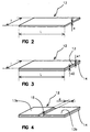
- FIG. 2 thus shows a receiving element 12 which is produced in the form of a substantially rectangular strip length L between 20mm and 70mm and width l between 2mm and 5mm.
- This strip also has a thickness e of the order of a few tenths of a mm (0.1 to 0.5mm).
- the value of the width l which is less than 10 mm ensures during the emission of microwaves with a power of 1000 W an electrical breakdown between the edges of this smaller dimension. This results in a triggering of the reaction between Magnesium and the Teflon / Viton pair.
- the reduced thickness (e) ensures obtaining the effect of point favoring the formation of the arc.
- Such a receiving element is manufactured for example by rolling.
- FIG. 3 shows a receiver element 12 along a second embodiment of the invention. He too produced in the form of a substantially rectangular strip length L between 20mm and 70mm and width l between 2mm and 5mm.
- This element differs from the previous one in that it includes a layer 13 of a conductive material disposed on a layer 14 of an energetic material or one capable of reacting chemically with the conductive material.
- the thickness e1 of the conductive layer 13 is of the order 0.2mm and the thickness e2 of the energy layer 14 is around 1mm.
- Such a receiving element is manufactured for example in depositing a Viton solution in a solvent on a aluminum foil, then evaporating the solvent.
- the value of the width l less than 10 mm ensures when from microwave emission an electrical breakdown for a 1000 W power between the edges of this smaller dimension. This results in triggering the reaction between aluminum and Viton.
- FIG. 4 shows a receiver element 12 along a third embodiment of the invention.
- This mode also includes a layer 13 of a conductive material disposed on a layer 14 of an energetic material or likely to react chemically with the material driver.
- the conductive layer 13 is divided into two parts 13a and 13b separated by a groove 15 substantially rectangular and of width d.
- the width d is between 5 mm and 7 mm.
- Each of the parts 13a 13b has a width which is a sub multiple of the wavelength of microwaves. We favor thus the creation of an electric arc at the level of the groove 15 between the two parts 13a, 13b.
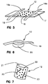
- FIG. 5 shows a receiver element 12 along a fourth embodiment of the invention.
- two strips of material are fixed conductor 16a, 16b on an insulating sheet 17.
- the strips 16a, 16b are fixed to the sheet 17 for example by gluing.
- An energetic material 18 is also deposited under grain shape on the insulating sheet 17.
- the strips 16a, 16b constitute conductive antennas. They have a length of 20 to 70mm and a width of 2 to 5mm, they are for example made of aluminum.
- the insulating sheet is for example a Mylar of a few tenths of a mm thick.
- Mylar is a registered trademark for designate plastics derived from xylene and commonly used to make thin films (capacitor dielectrics, magnetic tapes ).
- the energetic material 18 is a composition associating Boron and potassium nitrate (B / KNO3), for example in following proportions: 5 to 35% by mass of Boron (from preferably 20%) for 65 to 95% by mass of nitrate of potassium (preferably 80%). This composition is pasted on the mylar leaf.
- Microwave radiation will cause breakdown level of each antenna 16a, 16b.
- FIG. 6 shows a receiver element 12 along a fifth embodiment of the invention.
- the receiving element 12 comprises a conductive antenna 19 which is constituted by a ribbon aluminum 20 to 70mm long and 2 to 5mm wide.
- the microwave radiation will cause a breakdown between the ends of the ribbon and the initiation of the material energetic.
- FIG. 7 shows a receiver element 12 along a sixth embodiment of the invention.
- the receiving element includes a bag 21 of combustible material, for example asbestos cloth, inside which 1 g is placed in bulk 10 g of an energetic composition 22 in powder as well as at least one strip or wire of a conductive material 23 (here 2 bands).
- a conductive material 23 here 2 bands.
- the bag is substantially square with one side of the order 50 mm.
- the strip (s) or thread (s) 23 constitute the strip (s) conductive antennas that receive microwave radiation and which cause electrical breakdowns. The breakdown intervenes between the ends of the bands or wire and it ensures the ignition of energetic material 22.
- One or more sachets 21 can be arranged in existing propellant charges without the need to carry out a complete modification of the load as would impose it with the other modes previously described the realization of a homogeneous distribution of receptor elements throughout the load.
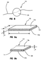
- FIG. 8 shows a receiver element 12 along a seventh embodiment of the invention.
- the receiving element 12 comprises a conductive antenna 24 which is constituted by a wire copper or magnesium 100 mm long and 0.1 mm diameter.
- This wire passes through a cylindrical tablet 25 of a material energetic or reactive, for example one of the compositions previously described combining Magnesium / polytetrafluoroethylene / chlorofluoroethylene copolymer, or Boron and potassium nitrate (possibly associated with nitrocellulose).
- a material energetic or reactive for example one of the compositions previously described combining Magnesium / polytetrafluoroethylene / chlorofluoroethylene copolymer, or Boron and potassium nitrate (possibly associated with nitrocellulose).
- the microwave radiation will cause a breakdown between the ends of the wire which will ensure the ignition of the tablet or initiation of the chemical reaction.
- FIG. 9a shows a receiver element 12 along a eighth embodiment of the invention.
- this element is made in the form of a strip substantially rectangular of length L between 70mm and 20mm and of width l between 2mm and 5mm.
- It comprises a layer 14 of an energetic material or likely to react chemically with the material conductor which is covered on both sides by layers 13c and 13d of a conductive material.
- the thickness (e) of the energetic or reactive layer 14 is around 1mm and the thickness of the conductive layers 13c, 13d is of the order of 0.2mm.
- Figure 9b shows a variant of this mode of embodiment, variant in which the conductive layers 13c and 13d have a length greater than that of the layer energetic or reactive 14. This results in an air gap 26 of thickness e between the two conductive layers, air gap which promotes the generation of electric arcs between conductive layers.
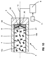
- Figure 1O shows the chamber of a weapon equipped with a initiation device according to a ninth embodiment of the invention.
- This mode differs from the mode according to FIG. 1 in that the propellant charge 4 (in grains) is placed in a case fuel 27, for example of cardboard impregnated with nitrocellulose, so as to constitute a load module propellant.
- a case fuel 27 for example of cardboard impregnated with nitrocellulose
- This charging module incorporates several elements receivers 12 according to the invention.
- Receiver elements 12a are evenly distributed in load 4, or else and preferably arranged at the level of the privileged plans located at distances from the microwave antenna that are multiples of the wavelength of the radiation.
- the elements 12a which are represented here have a structure similar to that of the elements according to the mode of realization of figure 6. But any other form of element receiver could be adopted.
- the charging module also incorporates elements 12b receivers which are made in the form of bands stuck on the internal surface of the fuel case 27.
- elements 12b receivers which are made in the form of bands stuck on the internal surface of the fuel case 27.
- the cone 8 constituting the transmitting antenna is constituted by a metal sheet made of conical aluminum fixed to a closing cover 28 secured to the case 27.
- the cover 28 is made of a combustible material, for example cardboard impregnated with nitrocellulose. He's wearing a axial contact 29 which comes into contact with a touch complementary 30 integral with the cylinder head 3, touch it even connected to the microwave generator 9.
- the antenna is combustible and / or destructible by the initiation of the composition.
- the antenna is therefore automatically renewed at each load of the weapon. This increases the reliability of ignition without penalizing operational implementation.
Landscapes
- Chemical & Material Sciences (AREA)
- Organic Chemistry (AREA)
- Engineering & Computer Science (AREA)
- General Engineering & Computer Science (AREA)
- Crystallography & Structural Chemistry (AREA)
- Chemical Kinetics & Catalysis (AREA)
- General Chemical & Material Sciences (AREA)
- Details Of Aerials (AREA)
- Air Bags (AREA)
Abstract
Description
- la figure 1 représente schématiquement la chambre d'une arme équipée d'un dispositif d'initiation selon l'invention,
- la figure 2 représente un premier mode de réalisation d'un dispositif d'initiation selon l'invention,
- la figure 3 représente un deuxième mode de réalisation d'un dispositif d'initiation selon l'invention,
- la figure 4 représente un troisième mode de réalisation d'un dispositif d'initiation selon l'invention,
- la figure 5 représente un quatrième mode de réalisation d'un dispositif d'initiation selon l'invention,
- la figure 6 représente un cinquième mode de réalisation d'un dispositif d'initiation selon l'invention,
- la figure 7 représente un sixième mode de réalisation d'un dispositif d'initiation selon l'invention,
- la figure 8 représente un septième mode de réalisation d'un dispositif d'initiation selon l'invention,
- la figure 9a représente un huitième mode de réalisation d'un dispositif d'initiation selon l'invention,
- la figure 9b est une variante de ce huitième mode de réalisation,
- la figure 1O représente schématiquement la chambre d'une arme équipée d'un dispositif d'initiation selon un neuvième mode de réalisation de l'invention.
Claims (20)
- Dispositif d'initiation d'une composition énergétique, telle qu'une composition pyrotechnique ou une charge propulsive (4) au moyen d'un générateur de micro ondes (9) et comportant au moins un élément récepteur (12) sensible aux micro ondes disposé au contact ou à proximité de la composition énergétique, dispositif caractérisé en ce que l'élément récepteur (12) comprend au moins un matériau conducteur associé à au moins un matériau énergétique ou susceptible de réagir chimiquement avec le matériau conducteur.
- Dispositif d'initiation selon la revendication 1, caractérisé en ce que l'élément récepteur (12) comporte au moins une antenne conductrice ayant une dimension inférieure ou égale à 10mm et qui est un sous-multiple de la longueur d'onde des micro ondes, de façon à assurer l'obtention d'un claquage électrique au niveau de cette dimension lorsque l'élément récepteur reçoit les micro ondes.
- Dispositif d'initiation selon une des revendications 1 ou 2, caractérisé en ce que le matériau conducteur est constitué par du carbone ou bien un métal.
- Dispositif d'initiation selon une des revendications 1 à 3, caractérisé en ce que le matériau énergétique ou susceptible de réagir chimiquement avec le matériau conducteur est choisi parmi les composés ou compositions suivantes :Oxyde de cuivre; polytétrafluoréthylène; copolymère de chlorofluoroéthylène; polytétrafluoréthylène/copolymère de chlorofluoroéthylène; Magnésium/oxyde de Cuivre; Magnésium /polytétrafluoréthylène/copolymère de chlorofluoro-éthylène; Aluminium/polytétrafluoréthylène/copolymère de chlorofluoro-éthylène; Bore/Nitrate de potassium; pellicule ou film de nitrocellulose plastifiée; nitrate de polyvinyle.
- Dispositif d'initiation selon une des revendications 1 à 4, caractérisé en ce que l'élément récepteur est formé par une bande d'un mélange homogène ayant la composition suivante:40% à 70 % en masse d'un matériau conducteur,40% à 30% en masse d'un matériau énergétique ou susceptible de réagir chimiquement avec le matériau conducteur,20% à 0% en masse de liant (éventuellement énergétique ou réactif avec le matériau conducteur).
- Dispositif d'initiation selon la revendication 5, caractérisé en ce que l'élément récepteur a la composition suivante :Magnésium : 40% à 70% en masse (de préférence 54%),Polytétrafluoréthylène: 40% à 30% en masse (de préférence 30%),copolymère de chlorofluoroéthylène: 20% à 0% en masse (de préférence 16%).
- Dispositif d'initiation selon une des revendications 1 à 4, caractérisé en ce que l'élément récepteur (12) est formé par une bande comprenant au moins une couche (13) d'un matériau conducteur disposée sur au moins une couche (14) d'un matériau énergétique ou bien susceptible de réagir chimiquement avec le matériau conducteur.
- Dispositif d'initiation selon la revendication 7, caractérisé en ce que la couche (13) de matériau conducteur est partagée en au moins deux parties séparées par au moins un sillon (15).
- Dispositif d'initiation selon une des revendications 7 ou 8, caractérisé en ce que la bande comprend au moins une couche (14) d'un matériau énergétique, ou bien susceptible de réagir chimiquement avec le matériau conducteur, intercalée entre deux couches (13c,13d) de matériau conducteur.
- Dispositif d'initiation selon la revendication 9, caractérisé en ce que les couches (13c,13d) de matériau conducteur sont plus longues que la couche (14) de matériau énergétique ou susceptible de réagir chimiquement avec le matériau conducteur et déterminent ainsi au moins un entrefer (26).
- Dispositif d'initiation selon une des revendications 7 à 10, caractérisé en ce que l'élément récepteur comprend comme matériau conducteur de l'aluminium et comme matériau énergétique ou susceptible de réagir chimiquement avec le matériau conducteur : une pellicule ou film de nitrocellulose plastifiée, du polytétrafluoréthylène, du nitrate de polyvinyle, un copolymère de chlorofluoroéthylène, une composition associant copolymère de chlorofluoroéthylène et polytétrafluoréthylène.
- Dispositif d'initiation selon une des revendications 1 à 11, caractérisé en ce que l'élément récepteur est réalisé sous la forme d'une bande de 20 à 70 mm de long et de 2 à 5mm de large.
- Dispositif d'initiation selon une des revendications 2 à 4, caractérisé en ce que l'antenne conductrice comprend au moins un fil (24) ou une bande (16a,16b,19,23) réalisée en un matériau conducteur et solidaire d'au moins un matériau énergétique ou susceptible de réagir chimiquement avec le matériau conducteur.
- Dispositif d'initiation selon la revendication 13, caractérisé en ce que l'antenne conductrice est un fil de cuivre ou d'aluminium de 30 à 50 mm de long solidaire d'un comprimé d'une composition associant Magnésium / polytétrafluoréthylène / copolymère de chlorofluoroéthylène ou encore d'une composition associant Bore et Nitrate de potassium.
- Dispositif d'initiation selon la revendication 13, caractérisé en ce que l'élément récepteur comprend au moins un fil ou une bande (16a,16b) solidaire d'une feuille isolante (17) sur laquelle est collé le matériau énergétique ou susceptible de réagir chimiquement avec le matériau conducteur (18).
- Dispositif d'initiation selon la revendication 13, caractérisé en ce que l'élément récepteur comprend un sachet combustible (21) qui renferme la composition énergétique (22) ou susceptible de réagir chimiquement avec le matériau conducteur et au moins une bande (23) ou fil d'un matériau conducteur.
- Dispositif d'initiation selon une des revendications 1 à 16, caractérisé en ce qu'il comprend une antenne émettrice conique (8) métallisée reliée au générateur de micro ondes (9) et disposée à en contact ou à proximité de la composition énergétique ou susceptible de réagir chimiquement avec le matériau conducteur, antenne réalisée en un matériau combustible ou destructible par l'initiation de la composition.
- Dispositif d'initiation selon la revendication 17, caractérisé en ce que l'antenne émettrice conique est solidaire d'un étui (27) d'un module de charge propulsive.
- Dispositif d'initiation selon la revendication 18, caractérisé en ce que au moins un élément récepteur (12b) est fixé à la surface interne de l'étui (27) du module de charge.
- Dispositif d'initiation selon une des revendications 17 à 19, caractérisé en ce que la distance entre l'antenne émettrice conique (8) et au moins un élément récepteur (12b) est un multiple de la longueur d'onde des micro ondes.
Applications Claiming Priority (2)
| Application Number | Priority Date | Filing Date | Title |
|---|---|---|---|
| FR9908902 | 1999-07-07 | ||
| FR9908902A FR2796141B1 (fr) | 1999-07-07 | 1999-07-07 | Dispositif d'initiation d'une composition energetique |
Publications (2)
| Publication Number | Publication Date |
|---|---|
| EP1067354A1 true EP1067354A1 (fr) | 2001-01-10 |
| EP1067354B1 EP1067354B1 (fr) | 2004-07-07 |
Family
ID=9547909
Family Applications (1)
| Application Number | Title | Priority Date | Filing Date |
|---|---|---|---|
| EP20000112869 Expired - Lifetime EP1067354B1 (fr) | 1999-07-07 | 2000-06-19 | Dispositif d'initiation d'une composition énergétique |
Country Status (3)
| Country | Link |
|---|---|
| EP (1) | EP1067354B1 (fr) |
| DE (1) | DE60011959T2 (fr) |
| FR (1) | FR2796141B1 (fr) |
Cited By (6)
| Publication number | Priority date | Publication date | Assignee | Title |
|---|---|---|---|---|
| WO2001027553A1 (fr) * | 1999-10-14 | 2001-04-19 | Fraunhofer-Gesellschaft zur Förderung der angewandten Forschung e.V. | Dispositif a charge propulsive pour armes a canon ou projections balistiques |
| WO2005043069A1 (fr) * | 2003-10-30 | 2005-05-12 | Gamma Kdg Systems Sa | Mecanisme de mise de feu a impulsion electromagnetique pour armes a feu et artillerie de gros calibre |
| CN109762373A (zh) * | 2019-01-21 | 2019-05-17 | 济南大学 | 一种含氟聚合物包覆型球形铝粉及其制备工艺与应用 |
| CN115536481A (zh) * | 2022-10-08 | 2022-12-30 | 北京理工大学 | 一种铝纤维增强铝/聚四氟乙烯含能材料的制备方法 |
| US11585622B1 (en) * | 2016-04-19 | 2023-02-21 | Triad National Security, Llc | Microwave ignition systems with launcher affixed to or located within a gun spindle |
| WO2026061727A1 (fr) * | 2024-09-23 | 2026-03-26 | Rheinmetall Waffe Munition Gmbh | Charge propulsive pouvant être allumée au moyen de micro-ondes et procédé d'allumage d'une telle charge propulsive |
Families Citing this family (2)
| Publication number | Priority date | Publication date | Assignee | Title |
|---|---|---|---|---|
| DE102009006079A1 (de) | 2009-01-26 | 2010-07-29 | Oao Znjj "Burevestnik" | Einrichtung zur Zündung der Wurfladung in der Geschosskammer eines Artilleriesystems mit hülsenloser Ladung |
| US10808649B2 (en) | 2016-08-18 | 2020-10-20 | Raytheon Company | Microwave ignition of electrically operated propellants |
Citations (6)
| Publication number | Priority date | Publication date | Assignee | Title |
|---|---|---|---|---|
| US3601054A (en) * | 1969-03-17 | 1971-08-24 | Unidynamics Phoenix | Method and apparatus for electromagnetically initiating ordnance |
| US3753811A (en) * | 1957-06-13 | 1973-08-21 | E Julian | Igniter composition |
| US4284868A (en) * | 1978-12-21 | 1981-08-18 | Amana Refrigeration, Inc. | Microwave oven |
| DE3237483A1 (de) * | 1982-10-09 | 1984-05-03 | Licentia Patent-Verwaltungs-Gmbh, 6000 Frankfurt | Anordnung zum kontaktlosen elektrischen anzuenden von explosiven ladungen |
| GB2241563A (en) * | 1989-04-18 | 1991-09-04 | Royal Ordnance Plc | Initiation of propellants |
| US5372069A (en) * | 1993-09-09 | 1994-12-13 | The United States Of America As Represented By The Secretary Of The Navy | Pyronol torch |
Family Cites Families (1)
| Publication number | Priority date | Publication date | Assignee | Title |
|---|---|---|---|---|
| FR2702832B1 (fr) | 1993-03-16 | 1995-06-09 | Lacroix E Tous Artifices | Dispositif d'initiation de composition pyrotechnique a risque attenue. |
-
1999
- 1999-07-07 FR FR9908902A patent/FR2796141B1/fr not_active Expired - Fee Related
-
2000
- 2000-06-19 DE DE2000611959 patent/DE60011959T2/de not_active Expired - Fee Related
- 2000-06-19 EP EP20000112869 patent/EP1067354B1/fr not_active Expired - Lifetime
Patent Citations (6)
| Publication number | Priority date | Publication date | Assignee | Title |
|---|---|---|---|---|
| US3753811A (en) * | 1957-06-13 | 1973-08-21 | E Julian | Igniter composition |
| US3601054A (en) * | 1969-03-17 | 1971-08-24 | Unidynamics Phoenix | Method and apparatus for electromagnetically initiating ordnance |
| US4284868A (en) * | 1978-12-21 | 1981-08-18 | Amana Refrigeration, Inc. | Microwave oven |
| DE3237483A1 (de) * | 1982-10-09 | 1984-05-03 | Licentia Patent-Verwaltungs-Gmbh, 6000 Frankfurt | Anordnung zum kontaktlosen elektrischen anzuenden von explosiven ladungen |
| GB2241563A (en) * | 1989-04-18 | 1991-09-04 | Royal Ordnance Plc | Initiation of propellants |
| US5372069A (en) * | 1993-09-09 | 1994-12-13 | The United States Of America As Represented By The Secretary Of The Navy | Pyronol torch |
Cited By (6)
| Publication number | Priority date | Publication date | Assignee | Title |
|---|---|---|---|---|
| WO2001027553A1 (fr) * | 1999-10-14 | 2001-04-19 | Fraunhofer-Gesellschaft zur Förderung der angewandten Forschung e.V. | Dispositif a charge propulsive pour armes a canon ou projections balistiques |
| WO2005043069A1 (fr) * | 2003-10-30 | 2005-05-12 | Gamma Kdg Systems Sa | Mecanisme de mise de feu a impulsion electromagnetique pour armes a feu et artillerie de gros calibre |
| US11585622B1 (en) * | 2016-04-19 | 2023-02-21 | Triad National Security, Llc | Microwave ignition systems with launcher affixed to or located within a gun spindle |
| CN109762373A (zh) * | 2019-01-21 | 2019-05-17 | 济南大学 | 一种含氟聚合物包覆型球形铝粉及其制备工艺与应用 |
| CN115536481A (zh) * | 2022-10-08 | 2022-12-30 | 北京理工大学 | 一种铝纤维增强铝/聚四氟乙烯含能材料的制备方法 |
| WO2026061727A1 (fr) * | 2024-09-23 | 2026-03-26 | Rheinmetall Waffe Munition Gmbh | Charge propulsive pouvant être allumée au moyen de micro-ondes et procédé d'allumage d'une telle charge propulsive |
Also Published As
| Publication number | Publication date |
|---|---|
| FR2796141A1 (fr) | 2001-01-12 |
| FR2796141B1 (fr) | 2002-07-12 |
| DE60011959D1 (de) | 2004-08-12 |
| EP1067354B1 (fr) | 2004-07-07 |
| DE60011959T2 (de) | 2005-08-04 |
Similar Documents
| Publication | Publication Date | Title |
|---|---|---|
| EP1067354B1 (fr) | Dispositif d'initiation d'une composition énergétique | |
| EP1030159B1 (fr) | Allumeur électropyrotechnique à sécurité d'allumage renforcé | |
| EP0030580B1 (fr) | Dispositif électrique d'allumage d'une substance pyrotechnique par induction électromagnétique | |
| WO2001077604A1 (fr) | Torche a plasma incorporant un fusible d'amorcage reactif et tube allumeur integrant une telle torche | |
| EP1160533B1 (fr) | Initiateur électro-pyrotechnique à pont en couche mince et à très basse énergie de fonctionnement | |
| FR2765319A1 (fr) | Procede d'amorcage electrique et de commande de la combustion d'une charge propulsive ainsi qu'une charge propulsive obtenue | |
| EP0924798B1 (fr) | Matériau composite structural absorbant les ondes radar et utilisation d'un tel matériau | |
| EP0499500A1 (fr) | Conteneur muni de moyens de liaison électrique | |
| FR2630821A1 (fr) | Dispositif de lancement electrothermique | |
| EP0717256B1 (fr) | Système de mise à feu par arc électrique d'une munition sans douille | |
| US10859358B1 (en) | Radio frequency igniter | |
| EP1273875B1 (fr) | Dispositif d'allumage pour un chargement propulsif | |
| FR2914737A1 (fr) | Leurre d'emission infrarouge | |
| CA3027439A1 (fr) | Allumage par micro-ondes de propulseurs electriques | |
| GB2332736A (en) | Plasma burning device for weapon systems | |
| FR2669724A1 (fr) | Detonateur laser a effet de projection de plaque. | |
| EP0296962A1 (fr) | Inflamatteur pour générateur pyrotechnique | |
| EP0412895B1 (fr) | Charge propulsive pyrotechnique à allumage électrique | |
| FR2725781A1 (fr) | Materiau d'allumage pour charge propulsive et systeme d'allumage ou tube allumeur mettant en oeuvre un tel materiau | |
| FR2490056A1 (fr) | Element de surface de chauffage electrique et son procede de fabrication | |
| EP1367355B1 (fr) | Amorce de sécurité à torche à plasma | |
| FR2737002A1 (fr) | Systeme d'allumage d'une charge propulsive, notamment pour munition d'artillerie de campagne, et son procede de fabrication | |
| FR2702273A1 (fr) | Tête pyrotechnique à moyens de dispersion perfectionnés. | |
| EP2559119B1 (fr) | Bougie d'allumage équipée de moyens de prévention des courts-circuits | |
| EP1367356A1 (fr) | Amorce de sécurité |
Legal Events
| Date | Code | Title | Description |
|---|---|---|---|
| PUAI | Public reference made under article 153(3) epc to a published international application that has entered the european phase |
Free format text: ORIGINAL CODE: 0009012 |
|
| AK | Designated contracting states |
Kind code of ref document: A1 Designated state(s): DE FR GB |
|
| AX | Request for extension of the european patent |
Free format text: AL;LT;LV;MK;RO;SI |
|
| 17P | Request for examination filed |
Effective date: 20010619 |
|
| AKX | Designation fees paid |
Free format text: DE FR GB |
|
| 17Q | First examination report despatched |
Effective date: 20030217 |
|
| GRAP | Despatch of communication of intention to grant a patent |
Free format text: ORIGINAL CODE: EPIDOSNIGR1 |
|
| GRAS | Grant fee paid |
Free format text: ORIGINAL CODE: EPIDOSNIGR3 |
|
| GRAA | (expected) grant |
Free format text: ORIGINAL CODE: 0009210 |
|
| AK | Designated contracting states |
Kind code of ref document: B1 Designated state(s): DE FR GB |
|
| REG | Reference to a national code |
Ref country code: GB Ref legal event code: FG4D Free format text: NOT ENGLISH |
|
| REF | Corresponds to: |
Ref document number: 60011959 Country of ref document: DE Date of ref document: 20040812 Kind code of ref document: P |
|
| GBT | Gb: translation of ep patent filed (gb section 77(6)(a)/1977) |
Effective date: 20040802 |
|
| PLBE | No opposition filed within time limit |
Free format text: ORIGINAL CODE: 0009261 |
|
| STAA | Information on the status of an ep patent application or granted ep patent |
Free format text: STATUS: NO OPPOSITION FILED WITHIN TIME LIMIT |
|
| 26N | No opposition filed |
Effective date: 20050408 |
|
| PGFP | Annual fee paid to national office [announced via postgrant information from national office to epo] |
Ref country code: DE Payment date: 20070530 Year of fee payment: 8 |
|
| PGFP | Annual fee paid to national office [announced via postgrant information from national office to epo] |
Ref country code: GB Payment date: 20070530 Year of fee payment: 8 |
|
| GBPC | Gb: european patent ceased through non-payment of renewal fee |
Effective date: 20080619 |
|
| PG25 | Lapsed in a contracting state [announced via postgrant information from national office to epo] |
Ref country code: DE Free format text: LAPSE BECAUSE OF NON-PAYMENT OF DUE FEES Effective date: 20090101 |
|
| PG25 | Lapsed in a contracting state [announced via postgrant information from national office to epo] |
Ref country code: GB Free format text: LAPSE BECAUSE OF NON-PAYMENT OF DUE FEES Effective date: 20080619 |
|
| PGFP | Annual fee paid to national office [announced via postgrant information from national office to epo] |
Ref country code: FR Payment date: 20100504 Year of fee payment: 11 |
|
| REG | Reference to a national code |
Ref country code: FR Ref legal event code: ST Effective date: 20120229 |
|
| PG25 | Lapsed in a contracting state [announced via postgrant information from national office to epo] |
Ref country code: FR Free format text: LAPSE BECAUSE OF NON-PAYMENT OF DUE FEES Effective date: 20110630 |