EP1065782B1 - Vorrichtung zur unterbrechungsfreien Stromversorgung mit Luftkühlung - Google Patents
Vorrichtung zur unterbrechungsfreien Stromversorgung mit Luftkühlung Download PDFInfo
- Publication number
- EP1065782B1 EP1065782B1 EP99112434A EP99112434A EP1065782B1 EP 1065782 B1 EP1065782 B1 EP 1065782B1 EP 99112434 A EP99112434 A EP 99112434A EP 99112434 A EP99112434 A EP 99112434A EP 1065782 B1 EP1065782 B1 EP 1065782B1
- Authority
- EP
- European Patent Office
- Prior art keywords
- housing
- cooling air
- heat exchanger
- cooling
- ups
- Prior art date
- Legal status (The legal status is an assumption and is not a legal conclusion. Google has not performed a legal analysis and makes no representation as to the accuracy of the status listed.)
- Expired - Lifetime
Links
Images
Classifications
-
- H—ELECTRICITY
- H02—GENERATION; CONVERSION OR DISTRIBUTION OF ELECTRIC POWER
- H02K—DYNAMO-ELECTRIC MACHINES
- H02K9/00—Arrangements for cooling or ventilating
- H02K9/24—Protection against failure of cooling arrangements, e.g. due to loss of cooling medium or due to interruption of the circulation of cooling medium
-
- H—ELECTRICITY
- H02—GENERATION; CONVERSION OR DISTRIBUTION OF ELECTRIC POWER
- H02J—ELECTRIC POWER NETWORKS; CIRCUIT ARRANGEMENTS OR SYSTEMS FOR SUPPLYING OR DISTRIBUTING ELECTRIC POWER; SYSTEMS FOR STORING ELECTRIC ENERGY
- H02J9/00—Circuit arrangements for emergency or stand-by power supply, e.g. for emergency lighting
-
- H—ELECTRICITY
- H02—GENERATION; CONVERSION OR DISTRIBUTION OF ELECTRIC POWER
- H02K—DYNAMO-ELECTRIC MACHINES
- H02K9/00—Arrangements for cooling or ventilating
- H02K9/10—Arrangements for cooling or ventilating by gaseous cooling medium flowing in closed circuit, a part of which is external to the machine casing
- H02K9/12—Arrangements for cooling or ventilating by gaseous cooling medium flowing in closed circuit, a part of which is external to the machine casing wherein the cooling medium circulates freely within the casing
-
- H—ELECTRICITY
- H02—GENERATION; CONVERSION OR DISTRIBUTION OF ELECTRIC POWER
- H02K—DYNAMO-ELECTRIC MACHINES
- H02K7/00—Arrangements for handling mechanical energy structurally associated with dynamo-electric machines, e.g. structural association with mechanical driving motors or auxiliary dynamo-electric machines
- H02K7/02—Additional mass for increasing inertia, e.g. flywheels
Definitions
- the invention relates to a device for uninterruptible Power supply according to the preamble of the claim 1.
- UPS uninterruptible power supply
- static UPS's are the interruptions of an AC or AC source with the help of stored in accumulators electrical energy bypass while dynamic UPS's for this purpose, stored in a rotating flywheel resort to kinetic energy.
- To keep this ready kinetic energy is permanently an electrical machine operated. It is operated as a motor, as long as the Desioder Three-phase current source supplies. In case of failure of the change or Three-phase source is switched to a generator mode, to use the stored kinetic energy.
- the present invention basically relates to both static as well as dynamic UPS's.
- the main application is however with dynamic UPS's.
- UPS power current electronic and Electrical components
- the Power losses of these components are also at relatively high Efficiencies of the UPSs of typically 95 to 99% absolute seen so large that they can be up very quickly without cooling would heat up to self-destruction.
- DE 1 813 592 A1 discloses a safety device for Exciter arrangement of electrical machines, in particular for Brushless exciter sets of turbogenerators, known.
- the Safety device specifically concerns the training of Air cooling of the exciter arrangements in a closed circuit.
- This closed circuit includes the exciter assemblies enclosing housing and cooling air conveying means for sucking Cooling air in the housing, to circulate the cooling air in the Housing and to blow the cooling air out of the housing to Dissipate heat energy.
- the cooling air is blown out in one Cooling air duct, from which the cooling air in the Normalberieb by a cooler passes back into the housing, the discharged Heat energy is delivered to the radiator.
- the safety device includes a bypass option of the radiator for the sucked into the housing cooling air.
- the cooler which causes an undesirable increase in temperature which comes to be cooled parts of the set of excitation is the blown out of the housing cooling air so no longer in the Cooler but directed into an exhaust duct; for that will be out of the Enclosed around the housing new cooling air sucked under Bypassing the radiator enters directly into the housing.
- the invention is based on the object, a device show according to the preamble of claim 1, in the with little equipment the risk of building up Contaminants in the housing of the UPS is avoided without this involves other dependencies and operating risks must be taken.
- the UPS according to the invention differs from the prior art Technology through two interlinked measures.
- On the one hand is for the normal trouble-free operation of the UPS the Cooling air in a closed to the environment of the UPS System led. She steps out of the case with the of the Power flow through electric and electronic Components in a heat exchanger and returns from the heat exchanger back into the case.
- the cooling air can therefore in Normal operation of the UPS no contamination in the housing register that build up over time.
- the heat exchanger which is passive according to the invention, allows the the cooling air withdrawn heat energy to a cooling medium transfer what easily for example from a completed Interior of a building where the UPS is located, dissipated can be. This is especially true when the cooling medium a liquid that is in a closed pipe system to be led.
- the new UPS has provisions for an emergency operation, if the heat exchanger due to technical Defects in the area of the heat exchanger itself or the Supply of cooling medium fails.
- the control of the new UPS increases the temperature over one predetermined limit value and then switches to an emergency operation, in which the cooling air blown out of the housing into the environment and is sucked from there back into the housing.
- This is Although accepted in the fact that impurities in the housing of the UPS, but this only applies to emergency operation.
- This Emergency operation typically only extends over a short time Period, as required, for example, to the UPS As a consumer connected computer systems controlled shut down.
- the UPS switches to prevent its Self-destruction due to overheating usually decreases because the heat absorption capacity of the ambient air in a closed Interior of a building in which the UPS is arranged is typically narrow.
- the dependence on the heat exchanger reduced to a degree which depends on the a separate air conditioning in the respective interior of a Building corresponds, in which the UPS is arranged. It is too take into account that a passive heat exchanger far less interference-prone and associated with far less technical effort is for example an air conditioner.
- a cooling medium for the heat exchanger is ideally water which is used by a heat dissipation system for a whole Building is provided.
- a heat dissipation system for a whole Building is provided.
- the heat exchanger is preferably in a heat exchanger housing arranged, which directly to the housing with the electric or electronic component is grown. This means, the housing and the heat exchanger housing then form a Unit.
- Cooling air inlet opening On the heat exchanger housing can on the cooling air inlet side a cooling air outlet opening which can be opened and closed by the control and on the cooling air outlet side of Heat exchanger one open and closed by the controller Cooling air inlet opening may be formed. These cooling air openings allow the cooling air in the second Operation of the new device to the heat exchanger over by the environment of the UPS, so in particular by a locked interior of a building in which the UPS is arranged circulates.
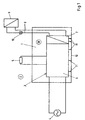
- a closed interior 1 is sketched, the stands for an interior 1 of a building, for example a basement room without permanent connection with the outside air 2, This alone sufficient cooling air for cooling a Device 3 for uninterruptible power supply (in following UPS).
- the UPS 3 is used for bridging of interruptions of an AC power source 4 in the supply at least one consumer 5.
- the AC source 4 is usually a public power grid.
- the consumer 5 is typically not in the interior 1 but somewhere arranged differently in the respective building.
- UPS 3 has one Housing 6, in the electrical and electronic components are provided, which flowed through by a power current become. This electrical energy is converted into heat energy.
- the resulting power loss is the UPS 3 in the range of about 2 to 3% of the total electrical Energy delivered from the AC power source 4 to the UPS 3 becomes.
- These Amounts of heat are circulated by cooling air circulating in the housing 6 is passed in a heat exchanger 7 to a cooling medium.
- the cooling medium is passed through lines 8 to a heat exchanger. 9 guided, the heat energy from the cooling medium to the outside air 2 and outside of the respective building or is arranged outside of this building.
- the cooled again Cooling medium is from the heat exchanger 9 to the heat exchanger. 7 returned.
- a circulation pump 10 is provided for the circulation of the cooling medium through the Lines 8 and the heat exchangers 7 and 9 are typical.
- the UPS 3 switches to emergency operation in that it circulates the cooling air circulated in the housing 6 no longer in the heat exchanger 7 but directly into their environment 28 within the interior 1 blows out and from there new Cooling air sucks into the housing 6.
- This will be the environment 28 of the UPS 3, d. H. the interior of the interior 1 heated.
- Feet 11 of the UPS 3 serve as spacers for the housing 6 and the heat exchanger 7 to the bottom 12th the interior 1, so that from the lines 8 or the Heat exchanger 7 expiring liquid cooling medium the function the UPS 3 in emergency operation is not endangered.
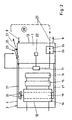
- FIG. 2 shows greatly simplified the structure of the UPS 3 inside of the housing 6 and in the region of a heat exchanger housing 13 of the heat exchanger 7.
- the housing 6 are different arranged electrical and electronic components, some be traversed by a power current. These include an electric machine 14 and other components 15 and 16.
- a controller 17 for switching the UPS 3 from the control mode on The emergency operation is not powered by a power, but only flows through its own supply and control currents.
- the Electric machine 14 has a stator 18 and a rotor 19 on.
- the rotor 19 serves as a flywheel for a kinetic Energy storage, in which the electric machine 14 as a motor is operated. To recover the stored kinetic Energy is the electric machine 14 operated as a generator.
- cooling air conveying organs 20 On the rotor 19 of the electric machine 14 are cooling air conveying organs 20, which is permanently connected to the rotor 19 circulate and for the promotion of the cooling air 21 through the housing 6 serve. That is, only by the air conveyors 20 is the cooling air 21 is sucked into the housing 6, in the housing 6 circulated and blown out of the housing 6 again. Ausgeblasen is the cooling air 21 in the heat exchanger 7, the housing 13th is attached directly and sealingly to the housing 6. The in the Heat exchanger 7 cooled cooling air is then returned to the Housing 6 sucked. When a temperature sensor 22 on the Heat exchanger 7, d. H.
- Cooling air outlet opening 25 is located in Heat exchanger housing 13 in the cooling air inlet area, while the cooling air inlet opening 26 in the heat exchanger housing 13 is located in the cooling air outlet region of the heat exchanger 7.
- the cooling air outlet opening 25 and the cooling air inlet opening 26 could also be provided directly in the housing 6, which is the electrical and electronic components 14 to 17 receives.
Landscapes
- Engineering & Computer Science (AREA)
- Power Engineering (AREA)
- Business, Economics & Management (AREA)
- Emergency Management (AREA)
- Cooling Or The Like Of Electrical Apparatus (AREA)
- Stand-By Power Supply Arrangements (AREA)
- Control Of Temperature (AREA)
- Motor Or Generator Cooling System (AREA)
Description
- Figur 1
- eine Übersicht über die Anordnung der Vorrichtung in einem Innenraum und
- Figur 2
- den prinzipiellen Aufbau der Vorrichtung.
- 1 -
- Innenraum
- 2 -
- Außenluft
- 3 -
- Vorrichtung (USV)
- 4 -
- Wechselstromquelle
- 5 -
- Verbraucher
- 6 -
- Gehäuse
- 7 -
- Wärmetauscher
- 8 -
- Leitung
- 9 -
- Wärmetauscher
- 10 -
- Umwälzpumpe
- 11 -
- Fuß
- 12 -
- Boden
- 13 -
- Wärmetauschergehäuse
- 14 -
- elektrische Maschine
- 15 -
- elektrisches Bauteil
- 16 -
- elektronisches Bauteil
- 17 -
- Steuerung
- 18 -
- Stator
- 19 -
- Rotor
- 20 -
- Kühlluftförderorgan
- 21 -
- Kühlluft
- 22 -
- Temperatursensor
- 23 -
- Klappe
- 24 -
- Klappe
- 25 -
- Kühlluftaustrittsöffnung
- 26 -
- Kühllufteintrittsöffnung
- 27 -
- Pfeil
- 28 -
- Umgebung
Claims (9)
- Vorrichtung für eine unterbrechungsfreien Stromversorgung zur Zwischenschaltung zwischen eine Wechsel- oder Drehstromquelle (4), deren Unterbrechungen zu überbrücken sind, und mindestens einen mit Wechsel- oder Gleichstrom zu versorgenden Verbraucher (5),dadurch gekennzeichnet,wobei die Vorrichtung (3), die zur Anordnung in einem abgeschlossenen Innenraum (1) eines Gebäudes vorgesehen ist,aufweist, undein Gehäuse (6),mindestens ein elektrisches oder elektronisches Bauteil (14 bis 16), das in dem Gehäuse angeordnet (6) ist und das von einem Leistungsstrom durchflossen wird, wobei elektrische Energie in Wärmeenergie umgewandelt wird, undKühlluftfördermittel zum Ansaugen von Kühlluft (21) in das Gehäuse (6), zum Umwälzen der Kühlluft (21) in dem Gehäuse (6) und zum Ausblasen der Kühlluft (21) aus dem Gehäuse (6), um die Wärmeenergie abzuführen,wobei eine Einrichtung vorgesehen sind, um der aus dem Gehäuse (6) ausgeblasenen Kühlluft (21) die Wärmeenergie wieder zu entziehen und auf ein Kühlmedium zu übertragen,daß bei einer ersten Betriebsweise der Vorrichtung (3) die aus dem Gehäuse (6) ausgeblasene Kühlluft (21) in einen passiven Wärmetauscher (7) eintritt,der als die Einrichtung vorgesehen ist, die der aus dem Gehäuse (6) ausgeblasenen Kühlluft (21) die Wärmeenergie wieder entzieht und auf das Kühlmedium überträgt, undaus dem die Kühlluft (21) anschließend wieder in das Gehäuse (6) angesaugt wird,wobei das Gehäuse (6), der Wärmetauscher (7) und etwaige dazwischen geschaltete Kühlluftleitungen gegenüber ihrer Umgebung (28) in dem Innenraum (1) abgedichtet sind,daß bei einer zweiten Betriebsweise der Vorrichtung (3) die Kühlluft (21) aus dem Gehäuse (6) in die Umgebung (21) in dem Innenraum (1) ausgeblasen und von dort wieder in das Gehäuse angesaugt (6) wird,daß eine Steuerung (17) vorgesehen ist, die von der ersten Betriebsweise auf die zweite Betriebsweise umschaltet, wenn ein Temperatursensor (22) an dem Wärmetauscher (7) eine Temperatur registriert, die oberhalb eines vorgegebenen Grenzwerts liegt, unddaß die Leitungen (8) für das Kühlmedium Teil eines Wärmeabfuhrsystems für ein ganzes Gebäude oder zumindest für wesentliche Teile eines Gebäudes sind.
- Vorrichtung nach Anspruch 1, dadurch gekennzeichnet, daß das Kühlmedium eine Flüssigkeit ist.
- Vorrichtung nach Anspruch 2, dadurch gekennzeichnet, daß die Flüssigkeit Wasser ist.
- Vorrichtung nach einem der Ansprüche 1 bis 3, dadurch gekennzeichnet, daß Leitungen (8) für das Kühlmedium zu einem außerhalb eines Gebäudes oder außen an einem Gebäude angeordneten Wärmetauscher (9) mit der Außenluft führen, wobei die Vorrichtung (3) in einem Innenraum (1) des Gebäudes angeordnet ist.
- Vorrichtung nach einem der Ansprüche 1 bis 4, dadurch gekennzeichnet, daß eine permanent betriebene elektrische Maschine (14) mit Rotor (18) und Stator (19) als elektrisches, in dem Gehäuse (6) angeordnetes Bauteil von dem Leistungsstrom durchflossen wird.
- Vorrichtung nach Anspruch 5, dadurch gekennzeichnet, daß der Rotor (19) der elektrischen Maschine (14) mit Kühlluftförderorganen (20) versehen ist, die Teil der Kühlluftfördermittel sind.
- Vorrichtung nach Anspruch 6, dadurch gekennzeichnet, daß die Kühlluftförderorgane (20) der allein bewegliche Teil der Kühlluftfördermittel sind.
- Vorrichtung nach einem der Ansprüche 1 bis 7, dadurch gekennzeichnet, daß der Wärmetauscher (7) für die Kühlluft ein Wärmetauschergehäuse (13) aufweist, das direkt an das Gehäuse (6) mit dem elektrischen oder elektronischen Bauteil angebaut ist.
- Vorrichtung nach einem der Ansprüche 1 bis 8, dadurch gekennzeichnet, daß der Wärmetauscher (7) für die Kühlluft ein Wärmetauschergehäuse (13) aufweist, in dem auf der Kühllufteintrittsseite eine von der Steuerung (17) öffenbare Kühlluftaustrittsöffnung (25) und auf der Kühlluftaustrittsseite des Wärmetauschers (7) eine von der Steuerung öffenbare Kühllufteintrittsöffnung (26) ausgebildet ist.
Priority Applications (6)
| Application Number | Priority Date | Filing Date | Title |
|---|---|---|---|
| DE59905192T DE59905192D1 (de) | 1999-06-30 | 1999-06-30 | Vorrichtung zur unterbrechungsfreien Stromversorgung mit Luftkühlung |
| EP99112434A EP1065782B1 (de) | 1999-06-30 | 1999-06-30 | Vorrichtung zur unterbrechungsfreien Stromversorgung mit Luftkühlung |
| AT99112434T ATE238625T1 (de) | 1999-06-30 | 1999-06-30 | Vorrichtung zur unterbrechungsfreien stromversorgung mit luftkühlung |
| ES99112434T ES2195478T3 (es) | 1999-06-30 | 1999-06-30 | Dispositivo para la alimentacion electrica ininterrumpida con refrigeracion por aire. |
| DE20011164U DE20011164U1 (de) | 1999-06-30 | 2000-06-24 | Vorrichtung zur unterbrechungsfreien Stromversorgung mit Luftkühlung |
| US09/606,615 US6424057B1 (en) | 1999-06-30 | 2000-06-29 | Uninterruptible power supply (UPS) system with primary air cooling |
Applications Claiming Priority (1)
| Application Number | Priority Date | Filing Date | Title |
|---|---|---|---|
| EP99112434A EP1065782B1 (de) | 1999-06-30 | 1999-06-30 | Vorrichtung zur unterbrechungsfreien Stromversorgung mit Luftkühlung |
Publications (2)
| Publication Number | Publication Date |
|---|---|
| EP1065782A1 EP1065782A1 (de) | 2001-01-03 |
| EP1065782B1 true EP1065782B1 (de) | 2003-04-23 |
Family
ID=8238454
Family Applications (1)
| Application Number | Title | Priority Date | Filing Date |
|---|---|---|---|
| EP99112434A Expired - Lifetime EP1065782B1 (de) | 1999-06-30 | 1999-06-30 | Vorrichtung zur unterbrechungsfreien Stromversorgung mit Luftkühlung |
Country Status (5)
| Country | Link |
|---|---|
| US (1) | US6424057B1 (de) |
| EP (1) | EP1065782B1 (de) |
| AT (1) | ATE238625T1 (de) |
| DE (2) | DE59905192D1 (de) |
| ES (1) | ES2195478T3 (de) |
Families Citing this family (2)
| Publication number | Priority date | Publication date | Assignee | Title |
|---|---|---|---|---|
| EP2483995A2 (de) * | 2009-10-01 | 2012-08-08 | Abb Ab | Kühlsystem für eine elektrische maschine |
| CN110752527B (zh) * | 2019-11-05 | 2020-11-03 | 国网上海市电力公司 | 一种配电箱自动测温降温设备 |
Family Cites Families (6)
| Publication number | Priority date | Publication date | Assignee | Title |
|---|---|---|---|---|
| CH109778A (de) * | 1924-04-01 | 1925-05-01 | Bbc Brown Boveri & Cie | Einrichtung für die geschlossene Ventilation von elektrischen Maschinen mit Rückkühlung der im Kreislauf zirkulierenden Luft. |
| DE1813592A1 (de) * | 1968-12-10 | 1970-09-24 | Siemens Ag | Sicherheitseinrichtung fuer Erregeranordnungen elektrischer Maschinen |
| US4580071A (en) * | 1983-07-28 | 1986-04-01 | Mitsubishi Denki Kabushiki Kaisha | Generator cooling apparatus |
| US6041850A (en) * | 1996-07-26 | 2000-03-28 | General Electric Company | Temperature control of electronic components |
| US6105875A (en) * | 1998-09-08 | 2000-08-22 | Lucent Technologies, Inc. | Direct air cooling of outdoor electronic cabinets |
| US6130818A (en) * | 1999-05-27 | 2000-10-10 | Hamilton Sundstrand Corporation | Electronic assembly with fault tolerant cooling |
-
1999
- 1999-06-30 EP EP99112434A patent/EP1065782B1/de not_active Expired - Lifetime
- 1999-06-30 DE DE59905192T patent/DE59905192D1/de not_active Expired - Lifetime
- 1999-06-30 ES ES99112434T patent/ES2195478T3/es not_active Expired - Lifetime
- 1999-06-30 AT AT99112434T patent/ATE238625T1/de active
-
2000
- 2000-06-24 DE DE20011164U patent/DE20011164U1/de not_active Expired - Lifetime
- 2000-06-29 US US09/606,615 patent/US6424057B1/en not_active Expired - Lifetime
Also Published As
| Publication number | Publication date |
|---|---|
| ES2195478T3 (es) | 2003-12-01 |
| DE59905192D1 (de) | 2003-05-28 |
| US6424057B1 (en) | 2002-07-23 |
| DE20011164U1 (de) | 2000-12-07 |
| ATE238625T1 (de) | 2003-05-15 |
| EP1065782A1 (de) | 2001-01-03 |
Similar Documents
| Publication | Publication Date | Title |
|---|---|---|
| EP3590315B1 (de) | Online-usv-anlage mit kombinierter luft- und wasserkühlung | |
| DE69722206T2 (de) | Hybrides klimaanlagensystem | |
| EP2591646B1 (de) | System und verfahren zur kühlung einer rechenanlage | |
| DE69421091T2 (de) | Luftkühlanlage | |
| DE10243775B4 (de) | Redundante Kühlvorrichtung für einen elektrischen U-Boot-Antriebsmotor | |
| DE60303558T2 (de) | Kompaktklimagerät für einen Schaltschrank | |
| WO2019096696A1 (de) | Kühlsystem für ein kraftfahrzeug und kraftfahrzeug mit einem solchen kühlsystem | |
| DE69814252T2 (de) | Umlaufgerät für isotherme Flüssigkeit | |
| EP2199706B1 (de) | Schaltschrank-Klimagerät und Verfahren zum Betreiben eines Solchen | |
| EP3218215B1 (de) | Kühlsystem | |
| WO2011082790A1 (de) | System und verfahren zur kühlung einer rechenanlage | |
| EP0903972B1 (de) | Vorrichtung zum Austausch von Wärmeenergie zwischen einem Gehäuseinnenraum und einer Umgebung | |
| EP1001671B1 (de) | Vorrichtung zur unterbrechungsfreien Stromversorgung | |
| DE10310307A1 (de) | Elektrische Maschine mit integrierter leistungselektronischer Einrichtung | |
| DE102007054724B4 (de) | Installationsschrank zur Aufnahme von elektrischen oder elektronischen Geräten, insbesondere von Recheneinrichtungen, sowie Einrichtung aufweisend mehrere solcher Installationsschränke, und Verfahren zum Betreiben einer solchen Einrichtung | |
| EP4197851B1 (de) | Ladestation für ein elektro- oder hybridfahrzeug | |
| EP2434853A1 (de) | Klimatisierungsvorrichtung zum Kühlen von Luft für einen Elektronikgeräteschrank oder dergleichen | |
| DE19815645C1 (de) | Umrichteranordnung mit Kühleinrichtung | |
| DE102010017168B4 (de) | Anordnung mitVerfahren zum Kühlen Wärme erzeugender Bauteile | |
| EP1065782A1 (de) | Vorrichtung zur unterbrechungsfreien Stromversorgung mit Luftkühlung | |
| EP0451325A2 (de) | Kaltwasser- und Soleaufbereitungsanlage | |
| EP2257147B1 (de) | Kühlgerät | |
| EP1174164B1 (de) | Container mit Energieversorgung und/oder Klimaanlage | |
| EP1260123B1 (de) | Schaltgehäuse mit einem kühlgerät | |
| EP3172494B1 (de) | Verfahren zum kühlen und anordnung aus luftkonditionierungsgerät und wärmeerzeugenden geräten |
Legal Events
| Date | Code | Title | Description |
|---|---|---|---|
| PUAI | Public reference made under article 153(3) epc to a published international application that has entered the european phase |
Free format text: ORIGINAL CODE: 0009012 |
|
| AK | Designated contracting states |
Kind code of ref document: A1 Designated state(s): AT BE DE ES FR GB IT NL |
|
| AX | Request for extension of the european patent |
Free format text: AL;LT;LV;MK;RO;SI |
|
| 17P | Request for examination filed |
Effective date: 20010220 |
|
| AKX | Designation fees paid |
Free format text: AT BE DE ES FR GB IT NL |
|
| 17Q | First examination report despatched |
Effective date: 20020222 |
|
| RAP1 | Party data changed (applicant data changed or rights of an application transferred) |
Owner name: RWE PILLER GMBH |
|
| GRAH | Despatch of communication of intention to grant a patent |
Free format text: ORIGINAL CODE: EPIDOS IGRA |
|
| GRAH | Despatch of communication of intention to grant a patent |
Free format text: ORIGINAL CODE: EPIDOS IGRA |
|
| GRAA | (expected) grant |
Free format text: ORIGINAL CODE: 0009210 |
|
| AK | Designated contracting states |
Designated state(s): AT BE DE ES FR GB IT NL |
|
| REG | Reference to a national code |
Ref country code: GB Ref legal event code: FG4D Free format text: NOT ENGLISH |
|
| REF | Corresponds to: |
Ref document number: 59905192 Country of ref document: DE Date of ref document: 20030528 Kind code of ref document: P |
|
| GBT | Gb: translation of ep patent filed (gb section 77(6)(a)/1977) | ||
| ET | Fr: translation filed | ||
| PLBE | No opposition filed within time limit |
Free format text: ORIGINAL CODE: 0009261 |
|
| STAA | Information on the status of an ep patent application or granted ep patent |
Free format text: STATUS: NO OPPOSITION FILED WITHIN TIME LIMIT |
|
| 26N | No opposition filed |
Effective date: 20040126 |
|
| REG | Reference to a national code |
Ref country code: FR Ref legal event code: PLFP Year of fee payment: 18 |
|
| REG | Reference to a national code |
Ref country code: FR Ref legal event code: PLFP Year of fee payment: 19 |
|
| REG | Reference to a national code |
Ref country code: FR Ref legal event code: PLFP Year of fee payment: 20 |
|
| PGFP | Annual fee paid to national office [announced via postgrant information from national office to epo] |
Ref country code: NL Payment date: 20180625 Year of fee payment: 20 Ref country code: DE Payment date: 20180412 Year of fee payment: 20 |
|
| PGFP | Annual fee paid to national office [announced via postgrant information from national office to epo] |
Ref country code: FR Payment date: 20180625 Year of fee payment: 20 Ref country code: BE Payment date: 20180625 Year of fee payment: 20 Ref country code: AT Payment date: 20180620 Year of fee payment: 20 |
|
| PGFP | Annual fee paid to national office [announced via postgrant information from national office to epo] |
Ref country code: ES Payment date: 20180723 Year of fee payment: 20 Ref country code: GB Payment date: 20180626 Year of fee payment: 20 Ref country code: IT Payment date: 20180622 Year of fee payment: 20 |
|
| REG | Reference to a national code |
Ref country code: DE Ref legal event code: R071 Ref document number: 59905192 Country of ref document: DE |
|
| REG | Reference to a national code |
Ref country code: NL Ref legal event code: MK Effective date: 20190629 |
|
| REG | Reference to a national code |
Ref country code: BE Ref legal event code: MK Effective date: 20190630 |
|
| REG | Reference to a national code |
Ref country code: GB Ref legal event code: PE20 Expiry date: 20190629 |
|
| REG | Reference to a national code |
Ref country code: AT Ref legal event code: MK07 Ref document number: 238625 Country of ref document: AT Kind code of ref document: T Effective date: 20190630 |
|
| PG25 | Lapsed in a contracting state [announced via postgrant information from national office to epo] |
Ref country code: GB Free format text: LAPSE BECAUSE OF EXPIRATION OF PROTECTION Effective date: 20190629 |
|
| REG | Reference to a national code |
Ref country code: ES Ref legal event code: FD2A Effective date: 20200806 |
|
| PG25 | Lapsed in a contracting state [announced via postgrant information from national office to epo] |
Ref country code: ES Free format text: LAPSE BECAUSE OF EXPIRATION OF PROTECTION Effective date: 20190701 |