EP0903972B1 - Vorrichtung zum Austausch von Wärmeenergie zwischen einem Gehäuseinnenraum und einer Umgebung - Google Patents
Vorrichtung zum Austausch von Wärmeenergie zwischen einem Gehäuseinnenraum und einer Umgebung Download PDFInfo
- Publication number
- EP0903972B1 EP0903972B1 EP98114271A EP98114271A EP0903972B1 EP 0903972 B1 EP0903972 B1 EP 0903972B1 EP 98114271 A EP98114271 A EP 98114271A EP 98114271 A EP98114271 A EP 98114271A EP 0903972 B1 EP0903972 B1 EP 0903972B1
- Authority
- EP
- European Patent Office
- Prior art keywords
- fluid
- housing
- air
- conduction system
- heat exchanger
- Prior art date
- Legal status (The legal status is an assumption and is not a legal conclusion. Google has not performed a legal analysis and makes no representation as to the accuracy of the status listed.)
- Expired - Lifetime
Links
Images


Classifications
-
- H—ELECTRICITY
- H05—ELECTRIC TECHNIQUES NOT OTHERWISE PROVIDED FOR
- H05K—PRINTED CIRCUITS; CASINGS OR CONSTRUCTIONAL DETAILS OF ELECTRIC APPARATUS; MANUFACTURE OF ASSEMBLAGES OF ELECTRICAL COMPONENTS
- H05K7/00—Constructional details common to different types of electric apparatus
- H05K7/20—Modifications to facilitate cooling, ventilating, or heating
- H05K7/20536—Modifications to facilitate cooling, ventilating, or heating for racks or cabinets of standardised dimensions, e.g. electronic racks for aircraft or telecommunication equipment
- H05K7/206—Air circulating in closed loop within cabinets wherein heat is removed through air-to-air heat-exchanger
-
- F—MECHANICAL ENGINEERING; LIGHTING; HEATING; WEAPONS; BLASTING
- F28—HEAT EXCHANGE IN GENERAL
- F28D—HEAT-EXCHANGE APPARATUS, NOT PROVIDED FOR IN ANOTHER SUBCLASS, IN WHICH THE HEAT-EXCHANGE MEDIA DO NOT COME INTO DIRECT CONTACT
- F28D9/00—Heat-exchange apparatus having stationary plate-like or laminated conduit assemblies for both heat-exchange media, the media being in contact with different sides of a conduit wall
-
- F—MECHANICAL ENGINEERING; LIGHTING; HEATING; WEAPONS; BLASTING
- F24—HEATING; RANGES; VENTILATING
- F24F—AIR-CONDITIONING; AIR-HUMIDIFICATION; VENTILATION; USE OF AIR CURRENTS FOR SCREENING
- F24F12/00—Use of energy recovery systems in air conditioning, ventilation or screening
- F24F12/001—Use of energy recovery systems in air conditioning, ventilation or screening with heat-exchange between supplied and exhausted air
-
- Y—GENERAL TAGGING OF NEW TECHNOLOGICAL DEVELOPMENTS; GENERAL TAGGING OF CROSS-SECTIONAL TECHNOLOGIES SPANNING OVER SEVERAL SECTIONS OF THE IPC; TECHNICAL SUBJECTS COVERED BY FORMER USPC CROSS-REFERENCE ART COLLECTIONS [XRACs] AND DIGESTS
- Y02—TECHNOLOGIES OR APPLICATIONS FOR MITIGATION OR ADAPTATION AGAINST CLIMATE CHANGE
- Y02B—CLIMATE CHANGE MITIGATION TECHNOLOGIES RELATED TO BUILDINGS, e.g. HOUSING, HOUSE APPLIANCES OR RELATED END-USER APPLICATIONS
- Y02B30/00—Energy efficient heating, ventilation or air conditioning [HVAC]
- Y02B30/56—Heat recovery units
Definitions
- the invention relates to a device for exchanging thermal energy between an interior of a housing, in particular for a telecommunication device, and an environment according to the preamble of Claim 1.
- the housing of an electrical device for example a transmission cabinet with contained radio equipment for a mobile Telephone system, in particular, includes electrical components which Generate waste heat. This waste heat is to avoid overheating of the electrical devices.
- GB-A-2 284 659 is a device for exchanging thermal energy between an interior of a housing and an environment known, this device having a heat exchanger block at least two separate and with each other in thermal energy transmitting contact standing fluid line system, wherein a first fluid line system with the housing interior and a second Fluid line system is connected to the environment.
- Any fluid line system is a fluid pump for delivering a first working fluid in the first fluid line system and a second working fluid in the second Associated fluid line system.
- a Temperature sensor connected fans provided, however, at Reaching a predefinable level, e.g. 15 ° C either in the speed is reduced or taken out of operation altogether become.
- US-A-4,582,130 is a heat exchanger for an electronics housing with a folding profile, with alternating on both sides every second fold sealed gas or dust-tight by a cover is known.
- an air / air heat exchanger With such an air / air heat exchanger, the Waste heat from the inside of an electronics housing is conducted to the outside if the electronics housing is closed dust-tight.
- the covers are used to manufacture the folded surface profile completely shaped on the folds.
- Such a folding surface profile in which the folds and the covers forming a single component is preferred manufactured as a deep-drawn part, so that the component Plastic can be made.
- the heat exchanger for an electronics housing from a folded profile with a depth of each Fold the fold profile approximately six times the width of each Fold the folding profile to thereby form in one
- a cover is closed.
- the cover is made of the only one Plastic piece molded on the folds of the folding profile.
- the Heat exchanger is designed so that on the side surface of the Folding surface profile, a support plate is attached, which over the folding surface profile protrudes and gas-tight with the side wall of the lid and the Side wall of the housing plate is assembled. It is essential gastight or dustproof connection of the panel with the folded profile and the side walls.
- the side wall is removable and gas-tight attached to the plate, for example with a seal, to make it possible to remove the lid to clean the folds. Openings, which are arranged in the area of the covers over the folds are in provided the support plate. Eventually, air becomes the second flow path fed through another opening.
- a fan for air circulation is arranged.
- a similar container is through the housing part formed with the support plate. In this case there is a fan for installed the other air circuit, as well as its electrical connections. For both air circuits it is assumed that the openings in the Open the support plate into the interior of the housing. After that, a device to exchange thermal energy between an interior of a Housing and an environment with at least two separate and are in contact with each other in thermal energy transfer Get fluid line systems.
- the known heat exchanger has no control device, which controls the speed of the fans to control the internal temperature in the To control the housing and to bring it to a predetermined temperature hold.
- GB-A-2 277 767 discloses a fixed telecommunications station, which includes a box-shaped body with a door that passes through Hinges are pivotally attached.
- the door has vents Plates on, two fans and a heat exchanger (optional a heating or cooling unit) so that the door is the device for regulation of the ambient conditions in the base station.
- This offers the possibility to create base stations with standard bodies, where Every single base station is equipped to meet certain environmental conditions (e.g. extreme heat or extreme cold) is justified by providing the body with a suitable door.
- this base station is such that the base station is box-shaped Body with a front opening that has a door is closable about a vertical axis with the help of three from each other spaced hinges is pivotally attached to the body.
- a security lock secures the door when closed.
- the air temperature in the base station is determined by in or on the door Regulated devices while the body is devoid of any device Regulation of environmental conditions is.
- the Door over panels with louvers and two fans, both on the Are attached inside the door, one of the fans being direct is arranged behind the plate with louvers.
- a honeycomb heat exchanger is also attached to the inside of the door.
- the door / body interface is with an environmental seal and a Equipped with a seal against electromagnetic radiation. leads to the fans are separable via the door / body connection Plug / socket connection connected so that the door as a separate Unit manufactured and separated from the body for replacement or repair can be.
- the fans suck in outside air during operation the plate with the louvers inside the base station.
- the outside air passes through the heat exchanger and indoor air from the base station also sucked through the heat exchanger, the air being the base station leaves through the plate, schematically represents the air flow and shows how the air sucked in from outside and the air from inside the base station via the heat exchanger into a heat exchange connection to be brought.
- the inside temperature in the base station is thus regulated by the device installed in or on the door, but takes place here, too, no internal temperature control via the fan speeds.
- US-A-3,559,728 relates to a self-contained cooling or heat exchange unit with a relatively shallow depth to enable the assembly of the Unit outside on the wall of housings and the like as the door of the Housing or as in a narrow space between housings ordered separation.
- This heat exchange unit is with a temperature control unit for regulating the temperature in a housing or cabinet containing electronic equipment and the like, this unit being self-contained and especially for the external mounting on the housing is suitable; it contains a container, which has at least one essentially hollow space which is connected to is connected to the housing and the first one essentially flat surface that closes the container and a first Has a pair of vertically spaced openings that are aligned with the cavity in Connect.
- the container With the container are assembly means for assembly connected to the unit on the outside of the housing, the pair of openings communicates with the inside of the housing. Also are electrically operable air circulation means provided in the container, the are isolated from the inside of the housing by the flat sealing surface and communicate with the cavity in the container to form a to generate forced flow in the housing by expelling air the room through an opening of the pair of openings in and through the housing and then through the other of the openings back into the Space to regulate the temperature of the air in the housing, where the flat surface also the electrical shield of the electronic Ensures equipment in the housing from faults caused by the electronic operation of the air circulation means that arise for Regulation of the housing temperature can be used.
- DE-A-37 17 540 discloses an inside or outside on a wall or Door of a control cabinet to be arranged with a heat exchanger Housing in which a heat exchanger unit and the unit are adjacent, two in an inner and an outer air circuit Blower units are arranged, the heat exchanger unit Air inlet and outlet openings assigned to the conveyed air are.
- This heat exchanger has one in the inner air circuit located heating device to prevent the formation of condensation and Connect condensation water because when the assemblies are turned off the temperature inside the control cabinet drops. there condensation or condensation can form.
- This control or Control device is located in the interior of the control cabinet Temperature sensor equipped.
- the blower unit of the inner air circuit cafe while the fan unit of the outer air circuit is switched off. In this way it can be guaranteed that the temperature inside the cabinet everywhere and is always above the dew point.
- a maximum temperature can be exceeded by switching off the Heating device and cooling by the heat exchanger unit in the can be prevented as described above.
- This temperature regulation unit enables temperature regulation in a control cabinet, which, however, is construction-intensive and with the no temperature control via fan speed detection or fan.
- the device consists in the control device is designed so that at least the least a first fluid pump of the first fluid line system continuously in the first speed range between 50% and 100% runs and the least a second fluid pump of the second fluid line system only from a predefinable temperature of the working fluid with 50% of the second Speed range runs and at maximum temperature of the working fluid has a maximum speed of 100%, the heat exchanger block is placed on the outside of the housing and openings for fluid flow and fluid leakage between the interior of the housing and the first fluid power system are provided and as a cross-flow plate exchanger is formed from a series of aluminum sheets exists, whose corners alternate to form two sets narrow air passages are compressed.
- the device according to the invention is therefore in particular with insulated, airtight or hermetically sealed housings applicable. Due to the arrangement of the heat exchanger block on the outer wall the housing creates a maintenance-friendly arrangement. The cross flow heat exchanger enables easy cleaning of the external airway.
- the first and / or second working fluid is expediently air and the fluid pumps are preferably fans, in particular radial fans, Axial fans or tangential fans.
- This control device is particularly preferred In addition, have a fault message output.
- the housing is expediently airtight, in particular hermetic, completed regarding the environment.
- At least one Working fluid is additional in a particularly preferred embodiment a heating device, in particular a resistance heating element, intended.
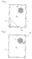
- the embodiment of a device 100 shown in FIG. 1 comprises a housing 10 and a heat exchanger block 11 with a first Fluid line system 12 as an internal circuit (Fig. 2), which with an interior 14 of the housing 10 communicates, and a second Fluid line system 16 as an external circuit, which with an environment communicates.
- Air is in each case in the fluid line systems 12, 16 as working fluid 18, 20 of fluid pumps 22 and 24 in the form of internal and outer radial fans circulated (Fig. 3).
- the Fluid pump 22 through the air 18 in the interior 14 of the housing 10 first fluid line system 12 and the fluid pump 24 the outside air each through the second fluid line system 16.
- the heat exchanger block 11 is designed as a counterflow plate exchanger and ensures heat exchange between the air 18 in the interior 14 of the housing 10 and the air 20 of the environment, so that thermal energy is transported out of the interior 14 to the outside.
- the heat exchanger block 11 designed as a cross plate heat exchanger.
- Cold ambient air 20 penetrates into the second fluid line system 16 of the heat exchanger block 11 via an opening 28 and comes warmed up via an opening 30 again, whereas warm interior air 18 of the housing 10 via an opening 32 in the first fluid line system 12 of the heat exchanger block 11 enters and exits cooled via an opening 34.
- FIG. 5 A bottom part 36 with corresponding openings 38 and 40 for the Air inlet 28 and air outlet 30 of the ambient air 20 is shown in Fig. 4.
- a cover part 42 with a corresponding opening 44 for the Air inlet 32 of the ambient air 18 can be seen in FIG. 5.
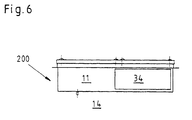
- 3 and 6 illustrate the inflow and outflow of the ambient air 20 and indoor air 18 into the heat exchanger block 11 or out of this via openings 28, 30, 32 and 34.
- control device in the first fluid line system 12 46 provided. This takes the temperature of the indoor air 18 and determines a speed of the Fluid pump 22 such that a maximum interior temperature in the housing is not exceeded.
- the heat exchanger block 11 is from a series of Made of aluminum sheets; the corners are alternately pressed by 2 To form a set of narrow air passages, once for the outside air 20 and once for the circulating air 18.
- the warm air flow 18 indicates heat the cold air flow 20, but without the air flows mixing.
- the mechanical data of the heat exchanger block in an exemplary embodiment are as follows: Dimensions 300 x 300 x 120 mm Weight 5.0 KG sheet distance 3 mm sheet thickness 0.4 mm amount of channels 19
- the fluid pumps 22, 24 are located at the top right and left of the Heat exchanger block 11 according to FIG. 2. These are radial fans, which are driven, for example, by collectorless 48 V DC motors become.
- the motors are speed controlled via pulse width modulation and are monitored for speed (Hall generator).
- the Fluid pump 22 runs continuously between 50% minimum and 100% at maximum Internal temperature.
- the fluid pump 24 runs from an internal temperature of 35 ° C. with 50% speed and goes up to 100% at maximum internal temperature.
- the motors are speed controlled via pulse width modulation at 48V DC and phase control at 230V AC.
- An external heater is optimally provided, at 7 ° C by a control unit off is activated.
- a control system used includes a circuit board with the following connections:
- the temperature sensor measures the temperature of the returned air 18 and adjusts the speeds of the fluid pumps 22, 24 accordingly on.
- the setpoint is, for example, 45 ° C.
- the fluid pump 22 starts at approx. 35 ° C and reaches the highest speed at the setpoint.
- the alarm temperature is 48 ° C.
- a potential-free contact is actuated by the temperature alarm and processed externally can be.
- the main data of the device are, for example, as follows: Dimensions 460 x 640 x 130 mm Weight 14 kg operating temperatur - 35 ° C to + 60 ° C Max. Indoor temperature 55 ° C Max. Outside temperature 40 ° C Max. Heat removal rate 64 W / K tension 48 V DC input 124 watts full load 2.6 amp Pick-up input 6 amps
Landscapes
- Engineering & Computer Science (AREA)
- Physics & Mathematics (AREA)
- Thermal Sciences (AREA)
- Mechanical Engineering (AREA)
- General Engineering & Computer Science (AREA)
- Aviation & Aerospace Engineering (AREA)
- Microelectronics & Electronic Packaging (AREA)
- Cooling Or The Like Of Electrical Apparatus (AREA)
- Buildings Adapted To Withstand Abnormal External Influences (AREA)
- Thermotherapy And Cooling Therapy Devices (AREA)
- Heat-Exchange Devices With Radiators And Conduit Assemblies (AREA)
Description
- Fig. 1
- eine Ausführungsform einer Vorrichtung zm Austausch von Wärmeenergie in einer schaubildlichen Darstellung,
- Fig. 2
- eine Ausführungsform der Vorrichtung in einer Schnittansicht,
- Fig. 3
- in einer Seitenansicht in Richtung des Pfeiles B in Figur 2, die Vorrichtung,
- Fig. 4
- in einer Draufsicht, die Vorrichtung,
- Fig. 5
- in einer Rückansicht die Vorrichtung und
- Fig. 6
- in einer weiteren Seitenansicht in Richtung des Pfeiles A in Fig. 2, die Vorrichtung.
- Durch das Konstruktionsprinzip der Einrichtung ist ein einfacher Ein- und Ausbau aller Komponenten (insbesondere Tauscherblock 11 und Fluidpumpen 22, 24) möglich; dies ist besonders servicefreundlich.
- Die durchgängige Ausführung des Gehäuses und Wärmetauschers in Aluminium führt zu einem korrosionsbeständigem Endgerät.
| Abmessungen | 300 x 300 x 120 mm |
| Gewicht | 5,0 KG |
| Blechabstand | 3 mm |
| Blechstärke | 0,4 mm |
| Anzahl der Kanäle | 19 |
| Ventilatorrad | 190mm |
| Luftfördermenge | 300 m3/h |
| Ext. statischer Druck | 100 Pa |
| Spannung | 48 V DC |
| Leistungsaufnahme | 62 Watt |
| Vollaststrom | 1,3 Amp |
| Anlaufstromaufnahme | 4 Amp |
| Temp. °C | <0°-5° | 5°-7° | 7°-25° | 25°-30° | 30°-35° | 35°-40° | 40°-43° | 43°-48° | >60° |
| Lüf-ter 50 % | 60 % | 60 % | 60 % | 70 % | 80 % | 80 % | 100 % | 100 % | 100% |
| Lüfter | off | Off | off | off | Off | 50 % | 70 % | 100 % | 100% |
| alarm Temp. | off | Off | off | off | Off | off | off | off | on |
| Heizer | on | On | off | off | Off | off | off | off | off |
| Abmessungen | 460 x 640 × 130 mm |
| Gewicht | 14 kg |
| Betriebstemperatur | - 35 °C bis + 60 °C |
| Max. Innentemperatur | 55 °C |
| Max. Außentemperatur | 40 °C |
| Max. Wärmeentzugsrate | 64 W/K |
| Spannung | 48 V DC |
| Leistungsaufnahme | 124 Watt |
| Vollaststrom | 2,6 Amp |
| Anlaufstromaufnahme | 6 Amp |
Claims (6)
- Vorrichtung zum Austausch von Wärmeenergie zwischen einem Innenraum (14) eines Gehäuses (10), insbesondere für ein Telekommunikationsgerät, und einer Umgebung, umfassend einen Wärmeaustauscherblock (11) mit wenigstens zwei voneinander getrennten und miteinander in wärmeenergieübertragenden Kontakt stehenden Fluidleitungssystemen (12, 16), wobei ein erstes Fluidleitungssystem (12) mit einem Gehäuseinnenraum (14) und ein zweites Fluidleitungssystem (16) mit der Umgebung verbunden ist und jedem Fluidleitungssystem (12, 16) jeweils wenigstens eine Fluidpumpe (22, 24) zum Fördern eines ersten Arbeitsfluids (18) im ersten Fluidleitungssystem (12) und eines zweiten Arbeitsfluids (20) im zweiten Fluidleitungssystem (16) zugeordnet ist, wobei im Innenraum (14) des isolierten, luftdichten bzw. hermetisch abgeschlossenen Gehäuses (10) oder im ersten Fluidleitungssystem eine Steuereinrichtung (46) vorgesehen ist, wobei mittels der Steuereinrichtung (46) mindestens ein erster Drehzahlbereich der wenigstens einen ersten Fluidpumpe (22) des ersten Fluidleitungssystems (12) und zusätzlich ein zweiter Drehzahlbereich der wenigstens einen zweiten Fluidpumpe (24) des zweiten Fluidleitungssystems (16) beeinflussbar ist, wobei der Steuereinrichtung (46) ein gemessener Wert einer Temperatur des ersten Arbeitsfluids (18) zuführbar ist und eine erste Drehzahl des mindestens einen ersten Drehzahlbereiches der wenigstens einen ersten Fluidpumpe (22) und zusätzlich eine zweite Drehzahl des zweiten Drehzahlbereiches der wenigstens einen zweiten Fluidpumpe (24) gemäß diesem Temperaturwert steuerbar ist, dadurch gekennzeichnet, dass die Steuereinrichtung (46) so ausgelegt ist, dass mindestens die wenigstens eine erste Fluidpumpe (22) des ersten Fluidleitungssystems (12) dauernd in dem ersten Drehzahlbereich zwischen 50 % und 100 % läuft und die wenigstens eine zweite Fluidpumpe (24) des zweiten Fluidleitungssystems erst ab einer vorgebbaren Temperatur des Arbeitsfluids (18) mit 50 % des zweiten Drehzahlbereiches läuft und bei maximaler Temperatur des Arbeitsfluids (18) eine maximale Drehzahl von 100 % aufweist, und dass der Wärmetauscherblock (11) außen auf das Gehäuse (10) aufgesetzt ist und Öffnungen (32, 34) zum Fluideinströmen und Fluidausströmen zwischen dem Innenraum (14) des Gehäuses (10) und dem ersten Fluidleitungssystem (12) vorgesehen sind und als Kreuzstromplattentauscher ausgebildet ist, der aus einer Serie von Aluminiumblechen besteht, deren Ecken abwechselnd zur Formung von zwei Satz enge Luftpassagen verpresst sind.
- Vorrichtung nach Anspruch 1,
dadurch gekennzeichnet, dass das erste und/oder zweite Arbeitsfluid (18, 20) Luft ist. - Vorrichtung (100, 200) nach Anspruch 1 oder 2,
dadurch gekennzeichnet, dass die Fluidpumpen (22, 24) Ventilatoren, insbesondere Radialventilatoren, Axialventilatoren oder Tangentialventilatoren sind. - Vorrichtung nach einem der Ansprüche 1 bis 3,
dadurch gekennzeichnet, dass die Steuereinrichtung (46) einen Störmeldeausgang aufweist. - Vorrichtung nach einem der Ansprüche 1 bis 4,
dadurch gekennzeichnet, dass das Gehäuse (10) luftdicht, insbesondere hermetisch, bezüglich der Umgebung abgeschlossen ist. - Vorrichtung nach einem der Ansprüche 1 bis 5,
dadurch gekennzeichnet, dass zusätzlich eine Heizeinrichtung, insbesondere ein Widerstandsheizelement, vorgesehen ist.
Applications Claiming Priority (2)
| Application Number | Priority Date | Filing Date | Title |
|---|---|---|---|
| DE29716682U DE29716682U1 (de) | 1997-09-17 | 1997-09-17 | Vorrichtung zum Austausch von Wärmeenergie zwischen einem Gehäuseinnenraum und einer Umgebung |
| DE29716682U | 1997-09-17 |
Publications (3)
| Publication Number | Publication Date |
|---|---|
| EP0903972A2 EP0903972A2 (de) | 1999-03-24 |
| EP0903972A3 EP0903972A3 (de) | 2000-02-23 |
| EP0903972B1 true EP0903972B1 (de) | 2004-11-24 |
Family
ID=8046107
Family Applications (1)
| Application Number | Title | Priority Date | Filing Date |
|---|---|---|---|
| EP98114271A Expired - Lifetime EP0903972B1 (de) | 1997-09-17 | 1998-07-30 | Vorrichtung zum Austausch von Wärmeenergie zwischen einem Gehäuseinnenraum und einer Umgebung |
Country Status (4)
| Country | Link |
|---|---|
| US (1) | US6170562B1 (de) |
| EP (1) | EP0903972B1 (de) |
| DE (2) | DE29716682U1 (de) |
| DK (1) | DK0903972T3 (de) |
Families Citing this family (14)
| Publication number | Priority date | Publication date | Assignee | Title |
|---|---|---|---|---|
| FI973881A7 (fi) * | 1997-10-03 | 1999-04-04 | Nokia Telecommunications Oy | Elektroniikkakaappi ja elektroniikkakaapin ilmakanavisto |
| DE29901658U1 (de) * | 1999-02-03 | 2000-07-13 | Burn, Heinz, Stüsslingen | Modulares Schaltschranksystem zur Aufnahme elektrischer und elektronischer Aggregate |
| FR2795977B1 (fr) * | 1999-07-06 | 2002-05-17 | Jouan | Enceinte de travail munie de moyens de recyclage de l'atmosphere |
| SK286594B6 (sk) * | 2000-03-02 | 2009-01-07 | Menerga Apparatebau Gmbh | Zariadenie na výrobu studenej vody na chladenie priestorov |
| US6504484B1 (en) * | 2000-09-26 | 2003-01-07 | Cohand Technology Co., Ltd. | Control method using power to prevent overheat inside of electric equipment |
| US6732787B1 (en) * | 2003-03-10 | 2004-05-11 | Avaya Technology Corp. | Cabinet upgrade system for in-service telecommunications cabinets |
| DE10315753B4 (de) * | 2003-04-04 | 2005-09-01 | Rittal Gmbh & Co. Kg | Fixierung einer Wärmetauscherkassette |
| US7475543B2 (en) * | 2005-11-14 | 2009-01-13 | Kenneth Bruce Martin | System and method for conveying thermal energy |
| JP4867727B2 (ja) * | 2007-03-13 | 2012-02-01 | パナソニック株式会社 | 冷却装置 |
| US8590602B2 (en) * | 2007-06-12 | 2013-11-26 | Asymblix, Llc | Heat exchanger for outdoor enclosures |
| DE202008003516U1 (de) * | 2008-03-12 | 2008-07-03 | Nft Nanofiltertechnik Gmbh | Kühlgerät für elektronische Bauelemente |
| US10139115B2 (en) * | 2010-03-26 | 2018-11-27 | Trane International Inc. | Air handling unit with inner wall space |
| US9759446B2 (en) | 2010-03-26 | 2017-09-12 | Trane International Inc. | Air handling unit with integral inner wall features |
| CN113864222A (zh) * | 2021-10-26 | 2021-12-31 | 浙江象睿机电设备有限公司 | 一种空气压缩机的智能控制系统 |
Family Cites Families (13)
| Publication number | Priority date | Publication date | Assignee | Title |
|---|---|---|---|---|
| US3559728A (en) * | 1968-11-29 | 1971-02-02 | Kooltronic Fan Co | Electronic equipment rack temperature control |
| DE2902909A1 (de) * | 1979-01-26 | 1980-07-31 | Eichenauer Fa Fritz | Schaltschrank-heizgeraet |
| DE3045326C2 (de) * | 1980-12-02 | 1982-10-21 | Autz & Hermann, 6900 Heidelberg | Zur staubfreien Kühlung eines Schaltschrankes dienender Wärmetauscher |
| JPS57127790A (en) * | 1981-01-30 | 1982-08-09 | Toshiba Corp | Refrigerating device for closed box |
| DE3311212A1 (de) * | 1983-03-28 | 1984-10-04 | Siemens AG, 1000 Berlin und 8000 München | Waermeaustauscher fuer einen elektronikschrank |
| GB8724263D0 (en) * | 1987-10-15 | 1987-11-18 | Bicc Plc | Electronic enclosure cooling system |
| US5174364A (en) * | 1988-09-21 | 1992-12-29 | Nec Corporation | Cooling abnormality detection system for electronic equipment |
| US4949218A (en) * | 1989-02-01 | 1990-08-14 | Fujitsu Limited | Cabinet with built-in cooling system |
| US5035281A (en) * | 1989-09-07 | 1991-07-30 | Mclean Midwest Corporation | Heat exchanger for cooling and method of servicing same |
| US5203178A (en) * | 1990-10-30 | 1993-04-20 | Norm Pacific Automation Corp. | Noise control of air conditioner |
| US5054545A (en) * | 1990-12-04 | 1991-10-08 | Northern Telecom Limited | Heat exchanger for a sealed cabinet |
| US5287244A (en) * | 1992-05-19 | 1994-02-15 | Sun Microsystems, Inc. | Computer housing with low noise cooling system |
| GB2277767B (en) * | 1993-05-06 | 1996-07-10 | Nokia Telecommunications Oy | Telecommunications base stations |
-
1997
- 1997-09-17 DE DE29716682U patent/DE29716682U1/de not_active Expired - Lifetime
-
1998
- 1998-07-30 EP EP98114271A patent/EP0903972B1/de not_active Expired - Lifetime
- 1998-07-30 DE DE59812297T patent/DE59812297D1/de not_active Expired - Fee Related
- 1998-07-30 DK DK98114271T patent/DK0903972T3/da active
- 1998-08-27 US US09/141,310 patent/US6170562B1/en not_active Expired - Fee Related
Also Published As
| Publication number | Publication date |
|---|---|
| DE59812297D1 (de) | 2004-12-30 |
| EP0903972A2 (de) | 1999-03-24 |
| EP0903972A3 (de) | 2000-02-23 |
| DK0903972T3 (da) | 2005-02-21 |
| DE29716682U1 (de) | 1997-11-06 |
| US6170562B1 (en) | 2001-01-09 |
Similar Documents
| Publication | Publication Date | Title |
|---|---|---|
| EP0903972B1 (de) | Vorrichtung zum Austausch von Wärmeenergie zwischen einem Gehäuseinnenraum und einer Umgebung | |
| DE69005851T2 (de) | Vollständig geschlossener elektrischer Motor. | |
| DE19983613B4 (de) | Steuerverfahren, Anordnung, Geräteschrank und Betriebsverfahren | |
| EP2949191B1 (de) | Wechselrichter mit zweiteiligem gehäuse | |
| EP1614333B1 (de) | Kühlungssystem für geräte- und netzwerkschränke und verfahren zur kühlung von geräte- und netzwerkschränken | |
| EP1832150B1 (de) | Kühlungssystem für geräte- und netzwerkschränke und verfahren zur kühlung von geräte- und netzwerkschränken | |
| DE29904928U1 (de) | Gehäuse mit einer Lüftereinrichtung und Lüftereinrichtung | |
| DE3642724A1 (de) | Elektromotor mit einem frequenzumrichter zur steuerung der motorbetriebsgroessen | |
| AT399075B (de) | Rückwand für ein gehäuse zur aufnahme elektrischer baugruppen | |
| EP3583668B1 (de) | Entwärmungsanordnung für einen schaltschrank | |
| DE4344054A1 (de) | Regelaggregat für eine Kraftfahrzeug-Klimaanlage | |
| DE3311212A1 (de) | Waermeaustauscher fuer einen elektronikschrank | |
| DE102008050778A1 (de) | Kühlanordnung für einen Elektro- oder Geräteschrank mit Luft-Luft-Wärmetauscherkassetten | |
| DE102015105500B3 (de) | Kühlgerät für die Schaltschrankklimatisierung | |
| DE19737531C2 (de) | Wärmetauscherbausatz und Klimatisierungsmeßgerät | |
| EP1026932B1 (de) | Modulares Schaltschranksystem zur Aufnahme elektrischer und elektronischer Aggregate | |
| DE19825602C2 (de) | Schaltschranksystem | |
| DE19917641A1 (de) | Modulares Schaltschranksystem zur Aufnahme elektrischer und elektronischer Aggregate | |
| WO1999065284A1 (de) | Wand- oder türteil oder einsatz für wand- oder türteil eines schaltschranksystems | |
| DE19902267C2 (de) | Lüftungsgerät | |
| DE102018211128B3 (de) | Anordnung mit einem Gehäuse und einer darin auf einem Gehäuseboden angeordneten Leistungselektronikschaltung | |
| DE102004020147A1 (de) | Anordnung umfassend ein Ladegerät und einen Akkupack | |
| EP1727411A2 (de) | Kühlvorrichtung für Serverschrank | |
| DE19817917A1 (de) | Gehäuse zur Aufnahme elektrischer und/oder elektronischer Schalteinheiten | |
| EP1065782B1 (de) | Vorrichtung zur unterbrechungsfreien Stromversorgung mit Luftkühlung |
Legal Events
| Date | Code | Title | Description |
|---|---|---|---|
| PUAI | Public reference made under article 153(3) epc to a published international application that has entered the european phase |
Free format text: ORIGINAL CODE: 0009012 |
|
| AK | Designated contracting states |
Kind code of ref document: A2 Designated state(s): DE DK FR GB IT SE |
|
| AX | Request for extension of the european patent |
Free format text: AL;LT;LV;MK;RO;SI |
|
| PUAL | Search report despatched |
Free format text: ORIGINAL CODE: 0009013 |
|
| TPAD | Observations filed by third parties |
Free format text: ORIGINAL CODE: EPIDOS TIPA |
|
| AK | Designated contracting states |
Kind code of ref document: A3 Designated state(s): AT BE CH CY DE DK ES FI FR GB GR IE IT LI LU MC NL PT SE |
|
| AX | Request for extension of the european patent |
Free format text: AL;LT;LV;MK;RO;SI |
|
| 17P | Request for examination filed |
Effective date: 20000714 |
|
| AKX | Designation fees paid |
Free format text: DE DK FR GB IT SE |
|
| 17Q | First examination report despatched |
Effective date: 20011003 |
|
| TPAD | Observations filed by third parties |
Free format text: ORIGINAL CODE: EPIDOS TIPA |
|
| RAP1 | Party data changed (applicant data changed or rights of an application transferred) |
Owner name: PFANNENBERG GMBH |
|
| GRAP | Despatch of communication of intention to grant a patent |
Free format text: ORIGINAL CODE: EPIDOSNIGR1 |
|
| GRAS | Grant fee paid |
Free format text: ORIGINAL CODE: EPIDOSNIGR3 |
|
| GRAA | (expected) grant |
Free format text: ORIGINAL CODE: 0009210 |
|
| AK | Designated contracting states |
Kind code of ref document: B1 Designated state(s): DE DK FR GB IT SE |
|
| REG | Reference to a national code |
Ref country code: GB Ref legal event code: FG4D Free format text: NOT ENGLISH |
|
| REF | Corresponds to: |
Ref document number: 59812297 Country of ref document: DE Date of ref document: 20041230 Kind code of ref document: P |
|
| GBT | Gb: translation of ep patent filed (gb section 77(6)(a)/1977) |
Effective date: 20041216 |
|
| REG | Reference to a national code |
Ref country code: DK Ref legal event code: T3 |
|
| REG | Reference to a national code |
Ref country code: SE Ref legal event code: TRGR |
|
| PG25 | Lapsed in a contracting state [announced via postgrant information from national office to epo] |
Ref country code: IT Free format text: LAPSE BECAUSE OF NON-PAYMENT OF DUE FEES Effective date: 20050730 Ref country code: GB Free format text: LAPSE BECAUSE OF NON-PAYMENT OF DUE FEES Effective date: 20050730 |
|
| PG25 | Lapsed in a contracting state [announced via postgrant information from national office to epo] |
Ref country code: SE Free format text: LAPSE BECAUSE OF NON-PAYMENT OF DUE FEES Effective date: 20050731 |
|
| PG25 | Lapsed in a contracting state [announced via postgrant information from national office to epo] |
Ref country code: DK Free format text: LAPSE BECAUSE OF NON-PAYMENT OF DUE FEES Effective date: 20050801 |
|
| PLBE | No opposition filed within time limit |
Free format text: ORIGINAL CODE: 0009261 |
|
| STAA | Information on the status of an ep patent application or granted ep patent |
Free format text: STATUS: NO OPPOSITION FILED WITHIN TIME LIMIT |
|
| ET | Fr: translation filed | ||
| 26N | No opposition filed |
Effective date: 20050825 |
|
| EUG | Se: european patent has lapsed | ||
| GBPC | Gb: european patent ceased through non-payment of renewal fee |
Effective date: 20050730 |
|
| PG25 | Lapsed in a contracting state [announced via postgrant information from national office to epo] |
Ref country code: FR Free format text: LAPSE BECAUSE OF NON-PAYMENT OF DUE FEES Effective date: 20060331 |
|
| REG | Reference to a national code |
Ref country code: DK Ref legal event code: EBP |
|
| REG | Reference to a national code |
Ref country code: FR Ref legal event code: ST Effective date: 20060331 |
|
| PGFP | Annual fee paid to national office [announced via postgrant information from national office to epo] |
Ref country code: DE Payment date: 20090923 Year of fee payment: 12 |
|
| PG25 | Lapsed in a contracting state [announced via postgrant information from national office to epo] |
Ref country code: DE Free format text: LAPSE BECAUSE OF NON-PAYMENT OF DUE FEES Effective date: 20110201 |
|
| REG | Reference to a national code |
Ref country code: DE Ref legal event code: R119 Ref document number: 59812297 Country of ref document: DE Effective date: 20110201 |