EP0903972B1 - Heat exchange device between inside a housing and environment - Google Patents
Heat exchange device between inside a housing and environment Download PDFInfo
- Publication number
- EP0903972B1 EP0903972B1 EP98114271A EP98114271A EP0903972B1 EP 0903972 B1 EP0903972 B1 EP 0903972B1 EP 98114271 A EP98114271 A EP 98114271A EP 98114271 A EP98114271 A EP 98114271A EP 0903972 B1 EP0903972 B1 EP 0903972B1
- Authority
- EP
- European Patent Office
- Prior art keywords
- fluid
- housing
- air
- conduction system
- heat exchanger
- Prior art date
- Legal status (The legal status is an assumption and is not a legal conclusion. Google has not performed a legal analysis and makes no representation as to the accuracy of the status listed.)
- Expired - Lifetime
Links
Images


Classifications
-
- H—ELECTRICITY
- H05—ELECTRIC TECHNIQUES NOT OTHERWISE PROVIDED FOR
- H05K—PRINTED CIRCUITS; CASINGS OR CONSTRUCTIONAL DETAILS OF ELECTRIC APPARATUS; MANUFACTURE OF ASSEMBLAGES OF ELECTRICAL COMPONENTS
- H05K7/00—Constructional details common to different types of electric apparatus
- H05K7/20—Modifications to facilitate cooling, ventilating, or heating
- H05K7/20536—Modifications to facilitate cooling, ventilating, or heating for racks or cabinets of standardised dimensions, e.g. electronic racks for aircraft or telecommunication equipment
- H05K7/206—Air circulating in closed loop within cabinets wherein heat is removed through air-to-air heat-exchanger
-
- F—MECHANICAL ENGINEERING; LIGHTING; HEATING; WEAPONS; BLASTING
- F28—HEAT EXCHANGE IN GENERAL
- F28D—HEAT-EXCHANGE APPARATUS, NOT PROVIDED FOR IN ANOTHER SUBCLASS, IN WHICH THE HEAT-EXCHANGE MEDIA DO NOT COME INTO DIRECT CONTACT
- F28D9/00—Heat-exchange apparatus having stationary plate-like or laminated conduit assemblies for both heat-exchange media, the media being in contact with different sides of a conduit wall
-
- F—MECHANICAL ENGINEERING; LIGHTING; HEATING; WEAPONS; BLASTING
- F24—HEATING; RANGES; VENTILATING
- F24F—AIR-CONDITIONING; AIR-HUMIDIFICATION; VENTILATION; USE OF AIR CURRENTS FOR SCREENING
- F24F12/00—Use of energy recovery systems in air conditioning, ventilation or screening
- F24F12/001—Use of energy recovery systems in air conditioning, ventilation or screening with heat-exchange between supplied and exhausted air
-
- Y—GENERAL TAGGING OF NEW TECHNOLOGICAL DEVELOPMENTS; GENERAL TAGGING OF CROSS-SECTIONAL TECHNOLOGIES SPANNING OVER SEVERAL SECTIONS OF THE IPC; TECHNICAL SUBJECTS COVERED BY FORMER USPC CROSS-REFERENCE ART COLLECTIONS [XRACs] AND DIGESTS
- Y02—TECHNOLOGIES OR APPLICATIONS FOR MITIGATION OR ADAPTATION AGAINST CLIMATE CHANGE
- Y02B—CLIMATE CHANGE MITIGATION TECHNOLOGIES RELATED TO BUILDINGS, e.g. HOUSING, HOUSE APPLIANCES OR RELATED END-USER APPLICATIONS
- Y02B30/00—Energy efficient heating, ventilation or air conditioning [HVAC]
- Y02B30/56—Heat recovery units
Definitions
- the invention relates to a device for exchanging thermal energy between an interior of a housing, in particular for a telecommunication device, and an environment according to the preamble of Claim 1.
- the housing of an electrical device for example a transmission cabinet with contained radio equipment for a mobile Telephone system, in particular, includes electrical components which Generate waste heat. This waste heat is to avoid overheating of the electrical devices.
- GB-A-2 284 659 is a device for exchanging thermal energy between an interior of a housing and an environment known, this device having a heat exchanger block at least two separate and with each other in thermal energy transmitting contact standing fluid line system, wherein a first fluid line system with the housing interior and a second Fluid line system is connected to the environment.
- Any fluid line system is a fluid pump for delivering a first working fluid in the first fluid line system and a second working fluid in the second Associated fluid line system.
- a Temperature sensor connected fans provided, however, at Reaching a predefinable level, e.g. 15 ° C either in the speed is reduced or taken out of operation altogether become.
- US-A-4,582,130 is a heat exchanger for an electronics housing with a folding profile, with alternating on both sides every second fold sealed gas or dust-tight by a cover is known.
- an air / air heat exchanger With such an air / air heat exchanger, the Waste heat from the inside of an electronics housing is conducted to the outside if the electronics housing is closed dust-tight.
- the covers are used to manufacture the folded surface profile completely shaped on the folds.
- Such a folding surface profile in which the folds and the covers forming a single component is preferred manufactured as a deep-drawn part, so that the component Plastic can be made.
- the heat exchanger for an electronics housing from a folded profile with a depth of each Fold the fold profile approximately six times the width of each Fold the folding profile to thereby form in one
- a cover is closed.
- the cover is made of the only one Plastic piece molded on the folds of the folding profile.
- the Heat exchanger is designed so that on the side surface of the Folding surface profile, a support plate is attached, which over the folding surface profile protrudes and gas-tight with the side wall of the lid and the Side wall of the housing plate is assembled. It is essential gastight or dustproof connection of the panel with the folded profile and the side walls.
- the side wall is removable and gas-tight attached to the plate, for example with a seal, to make it possible to remove the lid to clean the folds. Openings, which are arranged in the area of the covers over the folds are in provided the support plate. Eventually, air becomes the second flow path fed through another opening.
- a fan for air circulation is arranged.
- a similar container is through the housing part formed with the support plate. In this case there is a fan for installed the other air circuit, as well as its electrical connections. For both air circuits it is assumed that the openings in the Open the support plate into the interior of the housing. After that, a device to exchange thermal energy between an interior of a Housing and an environment with at least two separate and are in contact with each other in thermal energy transfer Get fluid line systems.
- the known heat exchanger has no control device, which controls the speed of the fans to control the internal temperature in the To control the housing and to bring it to a predetermined temperature hold.
- GB-A-2 277 767 discloses a fixed telecommunications station, which includes a box-shaped body with a door that passes through Hinges are pivotally attached.
- the door has vents Plates on, two fans and a heat exchanger (optional a heating or cooling unit) so that the door is the device for regulation of the ambient conditions in the base station.
- This offers the possibility to create base stations with standard bodies, where Every single base station is equipped to meet certain environmental conditions (e.g. extreme heat or extreme cold) is justified by providing the body with a suitable door.
- this base station is such that the base station is box-shaped Body with a front opening that has a door is closable about a vertical axis with the help of three from each other spaced hinges is pivotally attached to the body.
- a security lock secures the door when closed.
- the air temperature in the base station is determined by in or on the door Regulated devices while the body is devoid of any device Regulation of environmental conditions is.
- the Door over panels with louvers and two fans, both on the Are attached inside the door, one of the fans being direct is arranged behind the plate with louvers.
- a honeycomb heat exchanger is also attached to the inside of the door.
- the door / body interface is with an environmental seal and a Equipped with a seal against electromagnetic radiation. leads to the fans are separable via the door / body connection Plug / socket connection connected so that the door as a separate Unit manufactured and separated from the body for replacement or repair can be.
- the fans suck in outside air during operation the plate with the louvers inside the base station.
- the outside air passes through the heat exchanger and indoor air from the base station also sucked through the heat exchanger, the air being the base station leaves through the plate, schematically represents the air flow and shows how the air sucked in from outside and the air from inside the base station via the heat exchanger into a heat exchange connection to be brought.
- the inside temperature in the base station is thus regulated by the device installed in or on the door, but takes place here, too, no internal temperature control via the fan speeds.
- US-A-3,559,728 relates to a self-contained cooling or heat exchange unit with a relatively shallow depth to enable the assembly of the Unit outside on the wall of housings and the like as the door of the Housing or as in a narrow space between housings ordered separation.
- This heat exchange unit is with a temperature control unit for regulating the temperature in a housing or cabinet containing electronic equipment and the like, this unit being self-contained and especially for the external mounting on the housing is suitable; it contains a container, which has at least one essentially hollow space which is connected to is connected to the housing and the first one essentially flat surface that closes the container and a first Has a pair of vertically spaced openings that are aligned with the cavity in Connect.
- the container With the container are assembly means for assembly connected to the unit on the outside of the housing, the pair of openings communicates with the inside of the housing. Also are electrically operable air circulation means provided in the container, the are isolated from the inside of the housing by the flat sealing surface and communicate with the cavity in the container to form a to generate forced flow in the housing by expelling air the room through an opening of the pair of openings in and through the housing and then through the other of the openings back into the Space to regulate the temperature of the air in the housing, where the flat surface also the electrical shield of the electronic Ensures equipment in the housing from faults caused by the electronic operation of the air circulation means that arise for Regulation of the housing temperature can be used.
- DE-A-37 17 540 discloses an inside or outside on a wall or Door of a control cabinet to be arranged with a heat exchanger Housing in which a heat exchanger unit and the unit are adjacent, two in an inner and an outer air circuit Blower units are arranged, the heat exchanger unit Air inlet and outlet openings assigned to the conveyed air are.
- This heat exchanger has one in the inner air circuit located heating device to prevent the formation of condensation and Connect condensation water because when the assemblies are turned off the temperature inside the control cabinet drops. there condensation or condensation can form.
- This control or Control device is located in the interior of the control cabinet Temperature sensor equipped.
- the blower unit of the inner air circuit cafe while the fan unit of the outer air circuit is switched off. In this way it can be guaranteed that the temperature inside the cabinet everywhere and is always above the dew point.
- a maximum temperature can be exceeded by switching off the Heating device and cooling by the heat exchanger unit in the can be prevented as described above.
- This temperature regulation unit enables temperature regulation in a control cabinet, which, however, is construction-intensive and with the no temperature control via fan speed detection or fan.
- the device consists in the control device is designed so that at least the least a first fluid pump of the first fluid line system continuously in the first speed range between 50% and 100% runs and the least a second fluid pump of the second fluid line system only from a predefinable temperature of the working fluid with 50% of the second Speed range runs and at maximum temperature of the working fluid has a maximum speed of 100%, the heat exchanger block is placed on the outside of the housing and openings for fluid flow and fluid leakage between the interior of the housing and the first fluid power system are provided and as a cross-flow plate exchanger is formed from a series of aluminum sheets exists, whose corners alternate to form two sets narrow air passages are compressed.
- the device according to the invention is therefore in particular with insulated, airtight or hermetically sealed housings applicable. Due to the arrangement of the heat exchanger block on the outer wall the housing creates a maintenance-friendly arrangement. The cross flow heat exchanger enables easy cleaning of the external airway.
- the first and / or second working fluid is expediently air and the fluid pumps are preferably fans, in particular radial fans, Axial fans or tangential fans.
- This control device is particularly preferred In addition, have a fault message output.
- the housing is expediently airtight, in particular hermetic, completed regarding the environment.
- At least one Working fluid is additional in a particularly preferred embodiment a heating device, in particular a resistance heating element, intended.
- the embodiment of a device 100 shown in FIG. 1 comprises a housing 10 and a heat exchanger block 11 with a first Fluid line system 12 as an internal circuit (Fig. 2), which with an interior 14 of the housing 10 communicates, and a second Fluid line system 16 as an external circuit, which with an environment communicates.
- Air is in each case in the fluid line systems 12, 16 as working fluid 18, 20 of fluid pumps 22 and 24 in the form of internal and outer radial fans circulated (Fig. 3).
- the Fluid pump 22 through the air 18 in the interior 14 of the housing 10 first fluid line system 12 and the fluid pump 24 the outside air each through the second fluid line system 16.
- the heat exchanger block 11 is designed as a counterflow plate exchanger and ensures heat exchange between the air 18 in the interior 14 of the housing 10 and the air 20 of the environment, so that thermal energy is transported out of the interior 14 to the outside.
- the heat exchanger block 11 designed as a cross plate heat exchanger.
- Cold ambient air 20 penetrates into the second fluid line system 16 of the heat exchanger block 11 via an opening 28 and comes warmed up via an opening 30 again, whereas warm interior air 18 of the housing 10 via an opening 32 in the first fluid line system 12 of the heat exchanger block 11 enters and exits cooled via an opening 34.
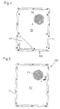
- FIG. 5 A bottom part 36 with corresponding openings 38 and 40 for the Air inlet 28 and air outlet 30 of the ambient air 20 is shown in Fig. 4.
- a cover part 42 with a corresponding opening 44 for the Air inlet 32 of the ambient air 18 can be seen in FIG. 5.
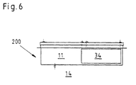
- 3 and 6 illustrate the inflow and outflow of the ambient air 20 and indoor air 18 into the heat exchanger block 11 or out of this via openings 28, 30, 32 and 34.
- control device in the first fluid line system 12 46 provided. This takes the temperature of the indoor air 18 and determines a speed of the Fluid pump 22 such that a maximum interior temperature in the housing is not exceeded.
- the heat exchanger block 11 is from a series of Made of aluminum sheets; the corners are alternately pressed by 2 To form a set of narrow air passages, once for the outside air 20 and once for the circulating air 18.
- the warm air flow 18 indicates heat the cold air flow 20, but without the air flows mixing.
- the mechanical data of the heat exchanger block in an exemplary embodiment are as follows: Dimensions 300 x 300 x 120 mm Weight 5.0 KG sheet distance 3 mm sheet thickness 0.4 mm amount of channels 19
- the fluid pumps 22, 24 are located at the top right and left of the Heat exchanger block 11 according to FIG. 2. These are radial fans, which are driven, for example, by collectorless 48 V DC motors become.
- the motors are speed controlled via pulse width modulation and are monitored for speed (Hall generator).
- the Fluid pump 22 runs continuously between 50% minimum and 100% at maximum Internal temperature.
- the fluid pump 24 runs from an internal temperature of 35 ° C. with 50% speed and goes up to 100% at maximum internal temperature.
- the motors are speed controlled via pulse width modulation at 48V DC and phase control at 230V AC.
- An external heater is optimally provided, at 7 ° C by a control unit off is activated.
- a control system used includes a circuit board with the following connections:
- the temperature sensor measures the temperature of the returned air 18 and adjusts the speeds of the fluid pumps 22, 24 accordingly on.
- the setpoint is, for example, 45 ° C.
- the fluid pump 22 starts at approx. 35 ° C and reaches the highest speed at the setpoint.
- the alarm temperature is 48 ° C.
- a potential-free contact is actuated by the temperature alarm and processed externally can be.
- the main data of the device are, for example, as follows: Dimensions 460 x 640 x 130 mm Weight 14 kg operating temperatur - 35 ° C to + 60 ° C Max. Indoor temperature 55 ° C Max. Outside temperature 40 ° C Max. Heat removal rate 64 W / K tension 48 V DC input 124 watts full load 2.6 amp Pick-up input 6 amps
Description
Die Erfindung betrifft eine Vorrichtung zum Austausch von Wärmeenergie zwischen einem Innenraum eines Gehäuses, insbesondere für ein Telekommunikationsgerät, und einer Umgebung gemäß dem Oberbegriff des Anspruchs 1.The invention relates to a device for exchanging thermal energy between an interior of a housing, in particular for a telecommunication device, and an environment according to the preamble of Claim 1.
Das Gehäuse einer elektrischen Vorrichtung, beispielsweise ein Übertragungsschrank mit einer darin enthaltenen Funkausrüstung für ein mobiles Telefonsystem, beinhaltet insbesondere elektrische Komponenten, welche Abwärme erzeugen. Diese Abwärme ist zur Vermeidung einer Überhitzung der elektrischen Geräte abzuführen.The housing of an electrical device, for example a transmission cabinet with contained radio equipment for a mobile Telephone system, in particular, includes electrical components which Generate waste heat. This waste heat is to avoid overheating of the electrical devices.
Da es sich bei derartigen Gehäusen üblicherweise um luftdicht bzw. hermetisch abgeschlossene Behälter handelt, ist eine Verwendung eines einfachen Abluftventilators nicht möglich.Since such housings are usually airtight or hermetic sealed container is a use of a simple exhaust fan not possible.
Durch die GB-A- 2 284 659 ist eine Vorrichtung zum Austausch von Wärmeenergie zwischen einem Innenraum eines Gehäuses und einer Umgebung bekannt, wobei diese Vorrichtung einen Wärmetauscherblock mit wenigstens zwei voneinander getrennten und miteinander in Wärmeenergie übertragendem Kontakt stehenden Fluidleitungssystem umfasst, wobei ein erstes Fluidleitungssystem mit dem Gehäuseinnenraum und ein zweites Fluidleitungssystem it der Umgebung verbunden ist. Jedem Fluidleitungssystem ist eine Fluidpumpe zum Fördern eines ersten Arbeitsfluids im ersten Fluidleitungssystem und ein zweites Arbeitsfluid im zweiten Fluidleitungssystem zugeordnet. Dabei sind drehzahlgeregelte, mit einem Temperatursensor verbundene Ventilatoren vorgesehen, die jedoch bei Erreichung eines vorgebbaren Levels, beispielsweise 15° C entweder in der Drehzahl reduziert oder gemeinsam komplett außer Betrieb genommen werden.GB-A-2 284 659 is a device for exchanging thermal energy between an interior of a housing and an environment known, this device having a heat exchanger block at least two separate and with each other in thermal energy transmitting contact standing fluid line system, wherein a first fluid line system with the housing interior and a second Fluid line system is connected to the environment. Any fluid line system is a fluid pump for delivering a first working fluid in the first fluid line system and a second working fluid in the second Associated fluid line system. Here are speed-controlled, with a Temperature sensor connected fans provided, however, at Reaching a predefinable level, e.g. 15 ° C either in the speed is reduced or taken out of operation altogether become.
Durch die US-A-4,582,130 ist ein Wärmetauscher für ein Elektronikgehäuse mit einem Faltflächenprofil, bei dem auf beiden Seiten abwechselnd jede zweite Falte gas- oder staubdicht durch eine Abdeckung verschlossen ist, bekannt. Mit einem derartigen Luft/Luft-Wärmetauscher soll die Abwärme aus dem Inneren eines Elektronikgehäuse nach außen geleitet werden, wenn das Elektronikgehäuse staubdicht geschlossen ist. Zur Erleichterung der Herstellung des Faltflächenprofils sind die Abdeckungen vollständig auf die Falten geformt. Ein derartiges Faltflächenprofil, bei dem die Falten und die Abdeckungen ein einziges Bauteil bilden, wird vorzugsweise als tiefgezogenes Teil hergestellt, so dass das Bauteil aus Kunststoff gefertigt werden kann. Danach besteht der Wärmeaustauscher für ein Elektronikgehäuse aus einem Faltflächenprofil mit einer Tiefe jeder Falte des Faltflächenprofils von ungefähr dem Sechsfachen der Breite jeder Falte des Faltflächenprofils, um dadurch das Formen in einem einzigen Tiefziehvorgang aus einem einzigen Kunststoffstück zu erleichtern, wobei abwechselnd auf beiden Seiten jede zweite Falte gasdicht durch eine Abdeckung verschlossen ist. Auch die Abdeckung ist aus dem einzigen Kunststoffstück auf die Falten des Faltflächenprofils geformt. Der Wärmeaustauscher ist dabei so ausgebildet, dass an der Seitenfläche des Faltflächenprofils eine Tragplatte angebracht ist, die über das Faltflächenprofil hinausragt und gasdicht mit der Seitenwand des Deckels und der Seitenwand der Gehäuseplatte zusammengefügt ist. Wesentlich ist die gas- oder staubdichte Verbindung der Platte mit dem Faltflächenprofil und den Seitenwänden. Die Seitenwand ist dabei abnehmbar und gasdicht an der Platte befestigt, beispielsweise mit einer Dichtung, um es möglich zu machen, den Deckel abzunehmen, um die Falten zu reinigen. Öffnungen, die im Bereich der Abdeckungen über den Falten angeordnet sind, sind in der Tragplatte vorgesehen. Schließlich wird Luft für den zweiten Strömungsweg durch eine andere Öffnung zugeführt. Mit dem Deckel und der Tragplatte wird ein Behältnis gebaut, in dem ein Ventilator für die Luftzirkulation angeordnet wird. Ein ähnliches Behältnis wird durch das Gehäuseteil mit der Tragplatte gebildet. In diesem Gehäuse ist ein Ventilator für den anderen Luftkreislauf eingebaut, sowie seine elektrischen Anschlüsse. Für beide Luftkreisläufe ist vorausgesetzt, dass die Öffnungen in der Tragplatte ins Innere des Gehäuses münden. Danach wird eine Vorrichtung zum Austausch von Wärmeenergie zwischen einem Innenraum eines Gehäuses und einer Umgebung mit wenigstens zwei voneinander getrennten und miteinander in Wärmeenergie übertragenden Kontakt stehenden Fluidleitungssystemen erhalten.US-A-4,582,130 is a heat exchanger for an electronics housing with a folding profile, with alternating on both sides every second fold sealed gas or dust-tight by a cover is known. With such an air / air heat exchanger, the Waste heat from the inside of an electronics housing is conducted to the outside if the electronics housing is closed dust-tight. To make things easier The covers are used to manufacture the folded surface profile completely shaped on the folds. Such a folding surface profile in which the folds and the covers forming a single component is preferred manufactured as a deep-drawn part, so that the component Plastic can be made. Then there is the heat exchanger for an electronics housing from a folded profile with a depth of each Fold the fold profile approximately six times the width of each Fold the folding profile to thereby form in one To facilitate deep drawing from a single piece of plastic, alternating gas-tight through every second fold on both sides a cover is closed. The cover is made of the only one Plastic piece molded on the folds of the folding profile. The Heat exchanger is designed so that on the side surface of the Folding surface profile, a support plate is attached, which over the folding surface profile protrudes and gas-tight with the side wall of the lid and the Side wall of the housing plate is assembled. It is essential gastight or dustproof connection of the panel with the folded profile and the side walls. The side wall is removable and gas-tight attached to the plate, for example with a seal, to make it possible to remove the lid to clean the folds. Openings, which are arranged in the area of the covers over the folds are in provided the support plate. Eventually, air becomes the second flow path fed through another opening. With the lid and the Carrier plate is built into a container in which a fan for air circulation is arranged. A similar container is through the housing part formed with the support plate. In this case there is a fan for installed the other air circuit, as well as its electrical connections. For both air circuits it is assumed that the openings in the Open the support plate into the interior of the housing. After that, a device to exchange thermal energy between an interior of a Housing and an environment with at least two separate and are in contact with each other in thermal energy transfer Get fluid line systems.
Danach ist ein erstes Fluidleitungssystem mit dem Gehäuseinnenraum und ein zweites Fluidleitungssystem mit der Umgebung verbunden. Der bekannte Wärmeaustauscher weist jedoch keine Steuereinrichtung auf, die die Drehzahl der Ventilatoren steuert, um die Innentemperatur in dem Gehäuse zu steuern und um diese auf eine vorgegebene Temperatur zu halten.After that is a first fluid line system with the housing interior and a second fluid line system connected to the environment. The known heat exchanger, however, has no control device, which controls the speed of the fans to control the internal temperature in the To control the housing and to bring it to a predetermined temperature hold.
Durch die GB-A-2 277 767 ist eine Telekommunikationsfeststation bekannt, die einen kastenförmigen Körper mit einer Tür umfasst, die durch Scharniere schwenkbar angebracht ist. Die Tür weist mit Luftschlitzen versehene Platten auf, zwei Ventilatoren und einen Wärmetauscher (optional eine Heizung oder Kühleinheit), so dass die Tür die Geräte zur Regulierung der Umgebungsbedingungen in der Feststation enthält. Dies bietet die Möglichkeit, Feststationen mit Standardkörpern zu schaffen, bei denen jede einzelne Feststation so ausgestattet ist, dass sie bestimmten Umgebungsbedingungen (beispielsweise extremer Wärme oder extremer Kälte) gerecht wird, indem der Körper mit einer geeigneten Tür versehen wird. Der Aufbau dieser Feststation ist derart, dass die Feststation einen kastenförmigen Körper mit einer Vorderöffnung aufweist, die mit einer Tür verschließbar ist, die um eine vertikale Achse mit Hilfe dreier voneinander beabstandeter Scharniere schwenkbar am Körper angebracht ist. Ein Sicherheitsschloss sichert die Tür bei geschlossener Stellung.GB-A-2 277 767 discloses a fixed telecommunications station, which includes a box-shaped body with a door that passes through Hinges are pivotally attached. The door has vents Plates on, two fans and a heat exchanger (optional a heating or cooling unit) so that the door is the device for regulation of the ambient conditions in the base station. This offers the possibility to create base stations with standard bodies, where Every single base station is equipped to meet certain environmental conditions (e.g. extreme heat or extreme cold) is justified by providing the body with a suitable door. The structure of this base station is such that the base station is box-shaped Body with a front opening that has a door is closable about a vertical axis with the help of three from each other spaced hinges is pivotally attached to the body. A security lock secures the door when closed.
Die Lufttemperatur in der Feststation wird durch in oder auf der Tür angebrachte Geräte reguliert, während der Körper frei von jeglichem Gerät zur Regulierung von Umgebungsbedingungen ist. Insbesondere verfügt die Tür über Platten mit Luftschlitzen und zwei Ventilatoren, die beide auf der Innenseite der Tür angebracht sind, wobei einer der Ventilatoren direkt hinter der Platte mit Luftschlitzen angeordnet ist. Ein Wabenwärmetauscher ist ebenfalls an der Innenseite der Tür angebracht.The air temperature in the base station is determined by in or on the door Regulated devices while the body is devoid of any device Regulation of environmental conditions is. In particular, the Door over panels with louvers and two fans, both on the Are attached inside the door, one of the fans being direct is arranged behind the plate with louvers. A honeycomb heat exchanger is also attached to the inside of the door.
Die Schnittstelle Tür/Körper ist mit einer Umgebungsdichtung und einer Dichtung gegen elektromagnetische Strahlung ausgestattet. Zuleitungen zu den Ventilatoren sind über die Tür-/Körperverbindung durch eine trennbare Stecker-/Buchsenverbindung angeschlossen, so dass die Tür als getrennte Einheit hergestellt und für Ersatz oder Reparatur vom Körper getrennt werden kann. Im Betrieb saugen die Ventilatoren Außenluft durch die Platte mit den Luftschlitzen ins Innere der Feststation. Die Außenluft streicht durch den Wärmetauscher und Innenluft aus der Feststation wird ebenfalls durch den Wärmetauscher gesaugt, wobei die Luft die Feststation durch die Platte verlässt, stellt schematisch den Luftstrom dar und zeigt, wie die von außen angesaugte Luft und die Luft aus dem Inneren der Feststation über den Wärmetauscher in eine Wärmeaustauschverbindung gebracht werden. Die Innentemperatur in der Feststation wird also durch das in oder auf der Tür angebrachte Gerät reguliert, jedoch erfolgt auch hier keine Innentemperatursteuerung über die Drehzahlen der Ventilatoren.The door / body interface is with an environmental seal and a Equipped with a seal against electromagnetic radiation. leads to the fans are separable via the door / body connection Plug / socket connection connected so that the door as a separate Unit manufactured and separated from the body for replacement or repair can be. The fans suck in outside air during operation the plate with the louvers inside the base station. The outside air passes through the heat exchanger and indoor air from the base station also sucked through the heat exchanger, the air being the base station leaves through the plate, schematically represents the air flow and shows how the air sucked in from outside and the air from inside the base station via the heat exchanger into a heat exchange connection to be brought. The inside temperature in the base station is thus regulated by the device installed in or on the door, but takes place here, too, no internal temperature control via the fan speeds.
Die US-A-3,559,728 betrifft eine in sich geschlossene Kühl- oder Wärmetauscheinheit mit relativ geringer Tiefe zur Ermöglichung der Montage der Einheit außen auf die Wand von Gehäusen und Ähnlichem als Tür des Gehäuses oder als in einem engen Zwischenraum zwischen Gehäusen angeordnete Trennung. Diese Wärmeaustauscheinheit ist mit einer Temperaturreguliereinheit zur Regulierung der Temperatur in einem Gehäuse oder Schrank, das elektronische Apparatur und Ähnliches enthält, versehen, wobei diese Einheit in sich abgeschlossen und insbesondere für die externe Montage auf das Gehäuse geeignet ist; sie umfasst ein Behältnis, das mindestens einen im Wesentlichen hohlen Raum aufweist, der mit dem Gehäuse in Verbindung steht und das eine erste im Wesentlichen flache Oberfläche verfügt, die das Behältnis verschließt und ein erstes Paar vertikal beabstandeter Öffnungen aufweist, die mit dem Hohlraum in Verbindung stehen. Mit dem Behältnis sind Montagemittel zur Montage der Einheit am Äußeren des Gehäuses verbunden, wobei das öffnungspaar mit dem Inneren des Gehäuses in Verbindung steht. Außerdem sind elektrisch betreibbare Luftzirkulationsmittel im Behältnis vorgesehen, die vom Inneren des Gehäuses durch die flache Verschlussfläche isoliert sind und mit dem Hohlraum in dem Behältnis in Verbindung stehen, um eine erzwungene Strömung in dem Gehäuse zu erzeugen, indem sie Luft aus dem Raum durch eine Öffnung des Öffnungspaares in und durch das Gehäuse treiben und dann durch die andere der Öffnungen zurück in den Raum, um die Temperatur der Luft in dem Gehäuse zu regulieren, wobei die flache Oberfläche ebenfalls die elektrische Abschirmung der elektronischen Apparatur in dem Gehäuse von Störungen sicherstellt, die durch den elektronischen Betrieb der Luftzirkulationsmittel entstehen, die zur Regulierung der Gehäusetemperatur verwendet werden.US-A-3,559,728 relates to a self-contained cooling or heat exchange unit with a relatively shallow depth to enable the assembly of the Unit outside on the wall of housings and the like as the door of the Housing or as in a narrow space between housings ordered separation. This heat exchange unit is with a temperature control unit for regulating the temperature in a housing or cabinet containing electronic equipment and the like, this unit being self-contained and especially for the external mounting on the housing is suitable; it contains a container, which has at least one essentially hollow space which is connected to is connected to the housing and the first one essentially flat surface that closes the container and a first Has a pair of vertically spaced openings that are aligned with the cavity in Connect. With the container are assembly means for assembly connected to the unit on the outside of the housing, the pair of openings communicates with the inside of the housing. Also are electrically operable air circulation means provided in the container, the are isolated from the inside of the housing by the flat sealing surface and communicate with the cavity in the container to form a to generate forced flow in the housing by expelling air the room through an opening of the pair of openings in and through the housing and then through the other of the openings back into the Space to regulate the temperature of the air in the housing, where the flat surface also the electrical shield of the electronic Ensures equipment in the housing from faults caused by the electronic operation of the air circulation means that arise for Regulation of the housing temperature can be used.
Die DE-A-37 17 540 offenbart einen innen oder außen an einer Wand oder Tür eines Schaltschrankes anzuordnenden Wärmetauscher, mit einem Gehäuse, in dem ein Wärmetauscheraggregat und dem Aggregat benachbart, zwei in einem inneren bzw. einem äußeren Luftkreislauf liegende Gebläseeinheiten angeordnet sind, wobei dem Wärmetauscheraggregat Lufteinlass- und Luftauslassöffnungen für die geförderte Luft zugeordnet sind. Dieser Wärmetauscher wiest eine in dem inneren Luftkreislauf befindliche Heizvorrichtung auf, um die Bildung von Kondens- und Schwitzwasser zu verbinden, denn wenn die Baugruppen abgeschaltet werden, sinkt die Temperatur im Inneren des Schaltschrankes ab. Dabei kann Kondens- oder Schwitzwasser entstehen. Um das zu vermeiden, wird sobald die Temperatur unter einen vorbestimmten Wert absinkt, die elektrische Energieversorgung der Heizvorrichtung durch eine Steuerungs- oder Regelungseinrichtung eingeschaltet. Diese Steuerungs- oder Regelungseinrichtung ist mit einem im Inneren des Schaltschrankes befindlichen Temperaturfühler ausgestattet. Gleichzeitig ist die Gebläseeinheit des inneren Luftkreislafes in Betrieb, während die Gebläseeinheit des äußeren Luftkreislaufes abgeschaltet ist. Auf diese Weise ist gewährleistbar, dass die Temperatur im Inneren des Schaltschrankes überall und immer über dem Taupunkt liegt.DE-A-37 17 540 discloses an inside or outside on a wall or Door of a control cabinet to be arranged with a heat exchanger Housing in which a heat exchanger unit and the unit are adjacent, two in an inner and an outer air circuit Blower units are arranged, the heat exchanger unit Air inlet and outlet openings assigned to the conveyed air are. This heat exchanger has one in the inner air circuit located heating device to prevent the formation of condensation and Connect condensation water because when the assemblies are turned off the temperature inside the control cabinet drops. there condensation or condensation can form. To avoid that, as soon as the temperature drops below a predetermined value, the electrical energy supply of the heating device by a control or control device switched on. This control or Control device is located in the interior of the control cabinet Temperature sensor equipped. At the same time, the blower unit of the inner air circuit cafe while the fan unit of the outer air circuit is switched off. In this way it can be guaranteed that the temperature inside the cabinet everywhere and is always above the dew point.
Die Überschreitung einer Maximaltemperatur kann durch Abschalten der Heizvorrichtung und Kühlung durch das Wärmetauscheraggregat in der oben beschriebenen Weise verhindert werden. A maximum temperature can be exceeded by switching off the Heating device and cooling by the heat exchanger unit in the can be prevented as described above.
Diese Temperaturregulierungseinheit ermöglicht eine Temperaturregulierung in einem Schaltschrank, die allerdings bauintensiv ist und mit der keine Temperatursteuerung über eine Drehzahlerfassung der Ventilatoren oder Lüfter erfolgt.This temperature regulation unit enables temperature regulation in a control cabinet, which, however, is construction-intensive and with the no temperature control via fan speed detection or fan.
Es ist daher Aufgabe der vorliegenden Erfindung, eine Vorrichtung der oben genannten Art zur Verfügung zu stellen, welche Wärme aus einem Gehäuseinnenraum nach außen abtransportiert und die Innentemperatur für die beteiligten Komponenten innerhalb tolerierter Grenzen aufrechterhält.It is therefore an object of the present invention to provide a device above type to provide what heat from a Housing interior transported away and the inside temperature for the components involved is maintained within tolerated limits.
Diese Aufgabe wird durch eine Vorrichtung der o. g. Art mit den in Anspruch 1 gekennzeichneten Merkmalen gelöst. This object is achieved by a device of the above. Kind with the claim 1 marked features solved.
Hiernach besteht die erfindungsgemäße Vorrichtung darin, dass die Steuereinrichtung so ausgelegt ist, dass mindestens die wenigstens eine erste Fluidpumpe des ersten Fluidleitungssystems dauernd in dem ersten Drehzahlbereich zwischen 50 % und 100 % läuft und die wenigstens eine zweite Fluidpumpe des zweiten Fluidleitungssystems erst ab einer vorgebbaren Temperatur des Arbeitsfluids mit 50 % des zweiten Drehzahlbereichs läuft und bei maximaler Temperatur des Arbeitsfluids eine maximale Drehzahl von 100 % aufweist, wobei der Wärmetauscherblock außen auf das Gehäuse aufgesetzt ist und Öffnungen zum Fluideinströmen und Fluidausströmen zwischen dem Innenraum des Gehäuses und dem ersten Fluidleistungssystem vorgesehen sind und als Kreuzstromplattentauscher ausgebildet ist, der aus einer Serie von Aluminiumblechen besteht, deren Ecken abwechselnd zur Formung von zwei Satz enge Luftpassagen verpresst sind.According to this, the device according to the invention consists in the control device is designed so that at least the least a first fluid pump of the first fluid line system continuously in the first speed range between 50% and 100% runs and the least a second fluid pump of the second fluid line system only from a predefinable temperature of the working fluid with 50% of the second Speed range runs and at maximum temperature of the working fluid has a maximum speed of 100%, the heat exchanger block is placed on the outside of the housing and openings for fluid flow and fluid leakage between the interior of the housing and the first fluid power system are provided and as a cross-flow plate exchanger is formed from a series of aluminum sheets exists, whose corners alternate to form two sets narrow air passages are compressed.
Dies hat den Vorteil, dass die Wärme indirekt abgeführt wird, also ohne Entnahme von Fluid aus dem Gehäuseinnenraum und ohne Vermischung von Fluid im Gehäuseinnenraum, dem ersten Arbeitsfluid, und dem zweiten Arbeitsfluid. Daher ist die erfindungsgemäße Vorrichtung insbesondere bei isolierten, luftdichten bzw. hermetisch abgeschlossenen Gehäusen anwendbar. Durch die Anordnung des Wärmetauscherblockes an der Außenwand des Gehäuses wird eine wartungsfreudige Anordnung geschaffen. Der Kreuzstromwärmetauscher ermöglicht eine leichte Reinigung des externen Luftweges.This has the advantage that the heat is dissipated indirectly, i.e. without it Removal of fluid from the interior of the housing and without mixing of fluid in the housing interior, the first working fluid, and the second Working fluid. The device according to the invention is therefore in particular with insulated, airtight or hermetically sealed housings applicable. Due to the arrangement of the heat exchanger block on the outer wall the housing creates a maintenance-friendly arrangement. The cross flow heat exchanger enables easy cleaning of the external airway.
Vorzugsweise Weitergestaltungen der Vorrichtung sind in den Unteransprüchen beschrieben.Further developments of the device are preferably in the subclaims described.
Zweckmäßigerweise ist das erste und/oder zweite Arbeitsfluid Luft und vorzugsweise sind die Fluidpumpen Ventilatoren, insbesondere Radialventilatoren, Axialventilatoren oder Tangentialventilatoren. The first and / or second working fluid is expediently air and the fluid pumps are preferably fans, in particular radial fans, Axial fans or tangential fans.
Diese Steuereinrichtung weist in besonders bevorzugter Weise zusätzlich einen Störmeldeausgang auf.This control device is particularly preferred In addition, have a fault message output.
Zweckmäßigerweise ist das Gehäuse luftdicht, insbesondere hermetisch, bezüglich der Umgebung abgeschlossen.The housing is expediently airtight, in particular hermetic, completed regarding the environment.
Zur Vermeidung des Unterschreitens eines Taupunktes wenigstens eines Arbeitsfluides ist in einer besonders bevorzugten Ausführungsform zusätzlich eine Heizeinrichtung, insbesondere ein Widerstandsheizelement, vorgesehen.To avoid falling below a dew point at least one Working fluid is additional in a particularly preferred embodiment a heating device, in particular a resistance heating element, intended.
Nachstehend wird die Erfindung anhand der beigefügten Zeichnungen näher erläutert. Diese zeigen in
- Fig. 1
- eine Ausführungsform einer Vorrichtung zm Austausch von Wärmeenergie in einer schaubildlichen Darstellung,
- Fig. 2
- eine Ausführungsform der Vorrichtung in einer Schnittansicht,
- Fig. 3
- in einer Seitenansicht in Richtung des Pfeiles B in Figur 2, die Vorrichtung,
- Fig. 4
- in einer Draufsicht, die Vorrichtung,
- Fig. 5
- in einer Rückansicht die Vorrichtung und
- Fig. 6
- in einer weiteren Seitenansicht in Richtung des Pfeiles A in Fig. 2, die Vorrichtung.
- Fig. 1
- an embodiment of a device for exchanging thermal energy in a diagram,
- Fig. 2
- 1 shows an embodiment of the device in a sectional view,
- Fig. 3
- In a side view in the direction of arrow B in Figure 2, the device,
- Fig. 4
- in a top view, the device,
- Fig. 5
- in a rear view the device and
- Fig. 6
- in a further side view in the direction of arrow A in Fig. 2, the device.
Die in Fig. 1 dargestellte Ausführungsform einer Vorrichtung 100 umfaßt
ein Gehäuse 10 und einen Wärmetauscherblock 11 mit einem ersten
Fluidleitungssystem 12 als Innenkreislauf (Fig. 2), welches mit einem Innenraum
14 des Gehäuses 10 in Verbindung steht, und einem zweiten
Fluidleitungssystem 16 als Außenkreislauf, welches mit einer Umgebung
in Verbindung steht. In den Fluidleitungssystemen 12, 16, wird jeweils Luft
als Arbeitsfluid 18, 20 von Fluidpumpen 22 und 24 in Form von inneren
und äußeren Radialventilatoren umgewälzt (Fig. 3). Hierbei fördert die
Fluidpumpe 22 die Luft 18 im Innenraum 14 des Gehäuses 10 durch das
erste Fluidleitungssystem 12 und die Fluidpumpe 24 die Außenluft jeweils
durch das zweite Fluidleitungssystem 16.The embodiment of a
Der Wärmetauscherblock 11 ist als Gegenstromplattentauscher ausgebildet
und sorgt für einen Wärmeaustausch zwischen der Luft 18 im Innenraum
14 des Gehäuses 10 und der Luft 20 der Umgebung, so daß Wärmeenergie
aus dem Innenraum 14 nach Außen abtransportiert wird. The
Die Fig. 2 bis 6 zeigen eine weitere Ausführungsform der Vorrichtung 200.
Hierbei ist, wie insbesondere aus Fig. 2 ersichtlich, der Wärmetauscherblock
11 als Kreuzplattenwärmetauscher ausgebildet. Kalte Umgebungsluft
20 dringt in das zweite Fluidleitungssystem 16 des Wärmetauscherblockes
11 über ein Öffnung 28 ein und tritt über eine Öffnung 30 aufgewärmt
wieder aus, wogegen warme Innenraumluft 18 des Gehäuses 10
über eine Öffnung 32 in das erste Fluidleitungssystem 12 des Wärmetauscherblockes
11 eintritt und über eine Öffnung 34 gekühlt wieder austritt.2 to 6 show a further embodiment of the
Ein Bodenteil 36 mit entsprechenden Öffnungen 38 und 40 für den
Lufteinlaß 28 und Luftauslaß 30 der Umgebungsluft 20 ist in Fig. 4 dargestellt.
Ein Deckelteil 42 mit einer entsprechenden Öffnung 44 für den
Lufteinlaß 32 der Umgebungsluft 18 ist aus Fig. 5 ersichtlich.A
Die Fig. 3 und 6 veranschaulichen das Ein- und Ausströmen der Umgebungsluft
20 und Innenraumluft 18 in den Wärmetauscherblock 11 hinein
bzw. aus diesem heraus über Öffnungen 28, 30, 32 und 34.3 and 6 illustrate the inflow and outflow of the
Wie sich aus Fig. 2 ergibt, ist im ersten Fluidleitungssystem 12 eine Steuereinrichtung
46 vorgesehen. Diese nimmt die Temperatur der Innenraumluft
18 auf und bestimmt gemäß diesem Wert eine Drehzahl der
Fluidpumpe 22 derart, daß eine maximale Innenraumtemperatur im Gehäuse
nicht überschritten wird. 2, there is a control device in the first
Die Verwendung von Aluminium hat dabei folgende Vorteile:
- Durch das Konstruktionsprinzip der Einrichtung ist ein einfacher Ein- und Ausbau aller Komponenten (insbesondere Tauscherblock 11 und Fluidpumpen 22, 24) möglich; dies ist besonders servicefreundlich.
- Die durchgängige Ausführung des Gehäuses und Wärmetauschers in Aluminium führt zu einem korrosionsbeständigem Endgerät.
- The construction principle of the device enables simple installation and removal of all components (in
particular exchanger block 11 and fluid pumps 22, 24); this is particularly easy to service. - The consistent design of the housing and heat exchanger in aluminum leads to a corrosion-resistant end device.
Der Wärmeaustauscherblock 11 ist aus einer Serie von
Aluminiumblechen gefertigt; die Ecken sind abwechselnd verpreßt um 2
Satz enge Luftpassagen zu formen, einmal für die Außenluft 20 und einmal
für die zirkulierende Luft 18. Der warme Luftstrom 18 gibt Wärme an
den Kaltluftstrom 20 ab, jedoch ohne daß sich die Luftströme ver-mischen.The
Die mechanischen Daten des Wärmeaustauscherblocks bei einer beispielhaften
Ausführungsform sind folgende:
Die Fluidpumpen 22, 24 befinden sich oben rechts und links an dem
Wärmetauscherblock 11 gemäß Fig. 2. Es handelt sich um Radialventilatoren,
die beispielsweise von kollektorlosen 48 V DC Motoren angetrieben
werden. Die Motore sind drehzahlgeregelt über Pulsbreitenmodulation
und werden drehzahlüberwacht (Hallgenerator). Die
Fluidpumpe 22 läuft dauernd zwischen 50 % minimum und 100 % bei maximaler
Innentemperatur. Die Fluidpumpe 24 läuft ab 35 °C Innentemperatur
mit 50 % Drehzahl und geht bis auf 100 % bei maximaler Innentemperatur.
Die Motoren sind drehzahlgeregelt über Pulsbreitenmodulation
bei 48V DC und Phasenausschnittregelung bei 230V AC.The fluid pumps 22, 24 are located at the top right and left of the
Für die Dimensionierung ergibt sich folgendes Beispiel:
Die o. g. Spezifikationen gelten beispielhaft für Außen- und Innenlüfter.The above Specifications apply to outdoor and indoor fans, for example.
Optimal ist eine externe Heizung vorgesehen, die bei 7 °C von einer Kontrolleinheit aus aktiviert wird.An external heater is optimally provided, at 7 ° C by a control unit off is activated.
Ein verwendetes Kontrollsystem beinhaltet eine Platine mit folgenden Anschlüssen:.A control system used includes a circuit board with the following connections:
Drehzahlkontrolle für die Fluidpumpen 22, 24 durch einen Temperatursensor auf der Platine; Anschlüsse für 2 Fluidpumpen und einem 48 V Ausgang für ein externes Heizungsrelais Anschluß für ein Alarmsignal (Störungslüfter) und Übertemperatur: potentialfreie Kontakte. Speed control for the fluid pumps 22, 24 by a temperature sensor on the board; Connections for 2 fluid pumps and a 48 V output for an external heating relay connection for an alarm signal (fault fan) and overtemperature: potential-free contacts.
Der Temperaturfühler mißt die Temperatur der zurückgeführten Luft 18
und paßt die Geschwindigkeiten der Fluidpumpen 22, 24 entsprechend
an. Der Sollwert ist beispielsweise 45 °C. Die Fluidpumpe 22 startet bei
ca. 35 °C und erreicht die höchste Drehzahl beim Sollwert.The temperature sensor measures the temperature of the returned
Die Alarmtemperatur liegt beispielsweise bei 48 °C. Bei Lüfterstörung oder Temperaturalarm wird ein potentialfreier Kontakt betätigt, der extern weiterverarbeitet werden kann.For example, the alarm temperature is 48 ° C. In case of fan failure or A potential-free contact is actuated by the temperature alarm and processed externally can be.
Es ergibt sich dabei folgende Steuertabelle:
Die Hauptdaten der Vorrichtung sind beispielhaft wie folgt:
Eine Wartung der Vorrichtung erfolgt beispielsweise folgendermaßen:
Bei bestimmten Komponenten kann es vorkommen, daß sie während der Lebenszeit des Gerätes ausgetauscht werden müssen. Folgende Abläufe sind zu beachten, wenn Ersatzteile ausgewechselt werden.With certain components it can happen that during the Lifetime of the device must be replaced. The following processes must be observed when replacing spare parts.
Vor Wartungsarbeiten ist das PLL stromlos zu schalten.
Claims (6)
- Device for the exchange of heat energy between the inside (14) of a housing (10), in particular for a telecommunication device, and the environment, comprising a heat exchanger block (11) with at least two fluid conduction systems (12, 16) separated from each other and in heat energy transmitting contact, whereby a first fluid conduction system (12) is connected with a housing inside (14) and a second fluid conduction system (16) is connected with the environment and at least one fluid pump (22, 24) for the delivery of a first working fluid (18) in the first fluid conduction system (12) and of a second working fluid (20) in the second fluid conduction system (16) is associated respectively to each fluid conduction system (12, 16), whereby a control device (46) is provided in the inside (14) of the insulated air tightly or hermetically sealed housing (10) or in the first fluid conduction system, whereby at least a first rpm range of the at least first fluid pump (22) of the first fluid conduction system (12) and additionally a second rpm range of the at least second fluid pump (24) of the second fluid conduction system (16) is influenceable by means of the control device (46), whereby a measured value of a temperature of the first working fluid (18) can be fed to the control device (46) and a first rpm of the at least one rpm range of the at least first fluid pump (22) and additionally a second rpm of the second rpm range of the at least second fluid pump (24) is controllable according to this temperature value, characterized in that the control device (46) is dimensioned such that at least the at least first fluid pump (22) of the first fluid conduction system (12) continuously runs in the first rpm range between 50 % and 100 % and the at least second fluid pump (24) of the second fluid conduction sytem runs only from a temperature of the working fluid (18) on which can be preset with 50 % of the second rpm range and has a maximal rpm of 100 % for a maximal temperature of the working fluid (18) and that the heat exchanger block (11) is placed outside on the housing (10) and openings (32, 34) for the fluid admission and fluid discharge between the inside (14) of the housing (10) and the first fluid conduction system (12) are provided and that the heat exchanger block is configured as countercurrent plate exchanger which is made of a series of aluminium sheets, the corners of which are pressed alternately for forming two groups of narrow air passages.
- Device according to claim 1,
characterized in that the first and/or second working fluid (18, 20) is air. - Device (100, 200) according to claim 1 or 2,
characterized in that the fluid pumps (22, 24) are fans, in particular radial fans, axial fans or tangential fans. - Device according to any of the claims 1 to 3,
characterized in that the control device (46) has a fault message output. - Device according to any of the claims 1 to 4,
characterized in that the housing (10) is air-tightly sealed, in particular hermetically sealed, with respect to the environment. - Device according to any of the claims 1 to 5,
characterized in that additionally a heating device, in particular a resistance heating element, is provided.
Applications Claiming Priority (2)
| Application Number | Priority Date | Filing Date | Title |
|---|---|---|---|
| DE29716682U | 1997-09-17 | ||
| DE29716682U DE29716682U1 (en) | 1997-09-17 | 1997-09-17 | Device for exchanging thermal energy between a housing interior and an environment |
Publications (3)
| Publication Number | Publication Date |
|---|---|
| EP0903972A2 EP0903972A2 (en) | 1999-03-24 |
| EP0903972A3 EP0903972A3 (en) | 2000-02-23 |
| EP0903972B1 true EP0903972B1 (en) | 2004-11-24 |
Family
ID=8046107
Family Applications (1)
| Application Number | Title | Priority Date | Filing Date |
|---|---|---|---|
| EP98114271A Expired - Lifetime EP0903972B1 (en) | 1997-09-17 | 1998-07-30 | Heat exchange device between inside a housing and environment |
Country Status (4)
| Country | Link |
|---|---|
| US (1) | US6170562B1 (en) |
| EP (1) | EP0903972B1 (en) |
| DE (2) | DE29716682U1 (en) |
| DK (1) | DK0903972T3 (en) |
Families Citing this family (14)
| Publication number | Priority date | Publication date | Assignee | Title |
|---|---|---|---|---|
| FI973881A (en) * | 1997-10-03 | 1999-04-04 | Nokia Telecommunications Oy | Electronic cabinet and air duct network for the electronics cabinet |
| DE29901658U1 (en) * | 1999-02-03 | 2000-07-13 | Burn Heinz | Modular control cabinet system for accommodating electrical and electronic units |
| FR2795977B1 (en) * | 1999-07-06 | 2002-05-17 | Jouan | WORK ENCLOSURE PROVIDED WITH ATMOSPHERE RECYCLING MEANS |
| PT1259769E (en) * | 2000-03-02 | 2005-03-31 | Menerga Appbau Gmbh | DEVICE FOR THE PRODUCTION OF COLD WATER FOR ROOM REFRIGERATION |
| US6504484B1 (en) * | 2000-09-26 | 2003-01-07 | Cohand Technology Co., Ltd. | Control method using power to prevent overheat inside of electric equipment |
| US6732787B1 (en) * | 2003-03-10 | 2004-05-11 | Avaya Technology Corp. | Cabinet upgrade system for in-service telecommunications cabinets |
| DE10315753B4 (en) * | 2003-04-04 | 2005-09-01 | Rittal Gmbh & Co. Kg | Fixation of a heat exchanger cassette |
| US7475543B2 (en) * | 2005-11-14 | 2009-01-13 | Kenneth Bruce Martin | System and method for conveying thermal energy |
| JP4867727B2 (en) * | 2007-03-13 | 2012-02-01 | パナソニック株式会社 | Cooling system |
| US8590602B2 (en) * | 2007-06-12 | 2013-11-26 | Asymblix, Llc | Heat exchanger for outdoor enclosures |
| DE202008003516U1 (en) * | 2008-03-12 | 2008-07-03 | Nft Nanofiltertechnik Gmbh | Cooling device for electronic components |
| US9759446B2 (en) | 2010-03-26 | 2017-09-12 | Trane International Inc. | Air handling unit with integral inner wall features |
| US10139115B2 (en) * | 2010-03-26 | 2018-11-27 | Trane International Inc. | Air handling unit with inner wall space |
| CN113864222A (en) * | 2021-10-26 | 2021-12-31 | 浙江象睿机电设备有限公司 | Intelligent control system of air compressor |
Family Cites Families (13)
| Publication number | Priority date | Publication date | Assignee | Title |
|---|---|---|---|---|
| US3559728A (en) * | 1968-11-29 | 1971-02-02 | Kooltronic Fan Co | Electronic equipment rack temperature control |
| DE2902909A1 (en) * | 1979-01-26 | 1980-07-31 | Eichenauer Fa Fritz | CONTROL CABINET HEATER |
| DE3045326C2 (en) * | 1980-12-02 | 1982-10-21 | Autz & Hermann, 6900 Heidelberg | Heat exchanger used for dust-free cooling of a switch cabinet |
| JPS57127790A (en) * | 1981-01-30 | 1982-08-09 | Toshiba Corp | Refrigerating device for closed box |
| DE3311212A1 (en) * | 1983-03-28 | 1984-10-04 | Siemens AG, 1000 Berlin und 8000 München | HEAT EXCHANGER FOR AN ELECTRONIC CABINET |
| GB8724263D0 (en) * | 1987-10-15 | 1987-11-18 | Bicc Plc | Electronic enclosure cooling system |
| US5174364A (en) * | 1988-09-21 | 1992-12-29 | Nec Corporation | Cooling abnormality detection system for electronic equipment |
| US4949218A (en) * | 1989-02-01 | 1990-08-14 | Fujitsu Limited | Cabinet with built-in cooling system |
| US5035281A (en) * | 1989-09-07 | 1991-07-30 | Mclean Midwest Corporation | Heat exchanger for cooling and method of servicing same |
| US5203178A (en) * | 1990-10-30 | 1993-04-20 | Norm Pacific Automation Corp. | Noise control of air conditioner |
| US5054545A (en) * | 1990-12-04 | 1991-10-08 | Northern Telecom Limited | Heat exchanger for a sealed cabinet |
| US5287244A (en) * | 1992-05-19 | 1994-02-15 | Sun Microsystems, Inc. | Computer housing with low noise cooling system |
| GB2277767B (en) * | 1993-05-06 | 1996-07-10 | Nokia Telecommunications Oy | Telecommunications base stations |
-
1997
- 1997-09-17 DE DE29716682U patent/DE29716682U1/en not_active Expired - Lifetime
-
1998
- 1998-07-30 EP EP98114271A patent/EP0903972B1/en not_active Expired - Lifetime
- 1998-07-30 DE DE59812297T patent/DE59812297D1/en not_active Expired - Fee Related
- 1998-07-30 DK DK98114271T patent/DK0903972T3/en active
- 1998-08-27 US US09/141,310 patent/US6170562B1/en not_active Expired - Fee Related
Also Published As
| Publication number | Publication date |
|---|---|
| EP0903972A2 (en) | 1999-03-24 |
| DE59812297D1 (en) | 2004-12-30 |
| US6170562B1 (en) | 2001-01-09 |
| DE29716682U1 (en) | 1997-11-06 |
| EP0903972A3 (en) | 2000-02-23 |
| DK0903972T3 (en) | 2005-02-21 |
Similar Documents
| Publication | Publication Date | Title |
|---|---|---|
| EP0903972B1 (en) | Heat exchange device between inside a housing and environment | |
| EP2949191B1 (en) | Inverter having two-part housing | |
| EP1614333B1 (en) | Cooling system for equipment and wiring cabinets and method for cooling equipment and wiring cabinets | |
| EP1832150B1 (en) | Cooling system for appliance cabinets and network cabinets, and method for cooling appliance cabinets and network cabinets | |
| DE3642724A1 (en) | ELECTRIC MOTOR WITH A FREQUENCY CONVERTER TO CONTROL THE MOTOR OPERATING SIZES | |
| DE4344054C2 (en) | Control unit for a motor vehicle air conditioning system | |
| AT399075B (en) | REAR PANEL FOR A HOUSING TO RECEIVE ELECTRICAL ASSEMBLIES | |
| WO2016162014A1 (en) | Electrical enclosure arrangement comprising an electrical enclosure line and a cooling device connected into the line | |
| DE19739309A1 (en) | Power supply unit | |
| DE2844672A1 (en) | Totally enclosed casing for electronic equipment - has heat exchange surfaces acting between internal and external forced air counter-flow paths | |
| DE3311212A1 (en) | HEAT EXCHANGER FOR AN ELECTRONIC CABINET | |
| DE19737531C2 (en) | Heat exchanger kit and air conditioning meter | |
| EP1026932B1 (en) | Modular cabinet for electrical and electronic aggregates | |
| DE19825602C2 (en) | cabinet system | |
| DE19917641A1 (en) | Modular control cabinet system for accommodating electrical and electronic units | |
| DE102008050778A1 (en) | Cooling arrangement for an electrical or equipment cabinet with air-to-air heat exchanger cassettes | |
| DE3405243C2 (en) | Slide-in cooling unit for switch cabinets | |
| DE102018211128B3 (en) | Arrangement with a housing and arranged therein on a housing bottom power electronics circuit | |
| DE19817917A1 (en) | Casing for housing electrical or electronic switch units | |
| DE102016124766B4 (en) | ENGINE DRIVE DEVICE THAT COOLS A HEAT SINK BY EXTERNAL AIR | |
| EP1065782B1 (en) | Device for supplying uninterrupted power with air cooling | |
| CN218037893U (en) | Server with water-cooling and air-cooling functions | |
| DE19757911C2 (en) | Control cabinet with an air conditioning device | |
| DE102004008513A1 (en) | Fan system for power distribution systems | |
| DE29824123U1 (en) | Control cabinet for accommodating electrical and electronic units |
Legal Events
| Date | Code | Title | Description |
|---|---|---|---|
| PUAI | Public reference made under article 153(3) epc to a published international application that has entered the european phase |
Free format text: ORIGINAL CODE: 0009012 |
|
| AK | Designated contracting states |
Kind code of ref document: A2 Designated state(s): DE DK FR GB IT SE |
|
| AX | Request for extension of the european patent |
Free format text: AL;LT;LV;MK;RO;SI |
|
| PUAL | Search report despatched |
Free format text: ORIGINAL CODE: 0009013 |
|
| TPAD | Observations filed by third parties |
Free format text: ORIGINAL CODE: EPIDOS TIPA |
|
| AK | Designated contracting states |
Kind code of ref document: A3 Designated state(s): AT BE CH CY DE DK ES FI FR GB GR IE IT LI LU MC NL PT SE |
|
| AX | Request for extension of the european patent |
Free format text: AL;LT;LV;MK;RO;SI |
|
| 17P | Request for examination filed |
Effective date: 20000714 |
|
| AKX | Designation fees paid |
Free format text: DE DK FR GB IT SE |
|
| 17Q | First examination report despatched |
Effective date: 20011003 |
|
| TPAD | Observations filed by third parties |
Free format text: ORIGINAL CODE: EPIDOS TIPA |
|
| RAP1 | Party data changed (applicant data changed or rights of an application transferred) |
Owner name: PFANNENBERG GMBH |
|
| GRAP | Despatch of communication of intention to grant a patent |
Free format text: ORIGINAL CODE: EPIDOSNIGR1 |
|
| GRAS | Grant fee paid |
Free format text: ORIGINAL CODE: EPIDOSNIGR3 |
|
| GRAA | (expected) grant |
Free format text: ORIGINAL CODE: 0009210 |
|
| AK | Designated contracting states |
Kind code of ref document: B1 Designated state(s): DE DK FR GB IT SE |
|
| REG | Reference to a national code |
Ref country code: GB Ref legal event code: FG4D Free format text: NOT ENGLISH |
|
| REF | Corresponds to: |
Ref document number: 59812297 Country of ref document: DE Date of ref document: 20041230 Kind code of ref document: P |
|
| GBT | Gb: translation of ep patent filed (gb section 77(6)(a)/1977) |
Effective date: 20041216 |
|
| REG | Reference to a national code |
Ref country code: DK Ref legal event code: T3 |
|
| REG | Reference to a national code |
Ref country code: SE Ref legal event code: TRGR |
|
| PG25 | Lapsed in a contracting state [announced via postgrant information from national office to epo] |
Ref country code: IT Free format text: LAPSE BECAUSE OF NON-PAYMENT OF DUE FEES Effective date: 20050730 Ref country code: GB Free format text: LAPSE BECAUSE OF NON-PAYMENT OF DUE FEES Effective date: 20050730 |
|
| PG25 | Lapsed in a contracting state [announced via postgrant information from national office to epo] |
Ref country code: SE Free format text: LAPSE BECAUSE OF NON-PAYMENT OF DUE FEES Effective date: 20050731 |
|
| PG25 | Lapsed in a contracting state [announced via postgrant information from national office to epo] |
Ref country code: DK Free format text: LAPSE BECAUSE OF NON-PAYMENT OF DUE FEES Effective date: 20050801 |
|
| PLBE | No opposition filed within time limit |
Free format text: ORIGINAL CODE: 0009261 |
|
| STAA | Information on the status of an ep patent application or granted ep patent |
Free format text: STATUS: NO OPPOSITION FILED WITHIN TIME LIMIT |
|
| ET | Fr: translation filed | ||
| 26N | No opposition filed |
Effective date: 20050825 |
|
| EUG | Se: european patent has lapsed | ||
| GBPC | Gb: european patent ceased through non-payment of renewal fee |
Effective date: 20050730 |
|
| PG25 | Lapsed in a contracting state [announced via postgrant information from national office to epo] |
Ref country code: FR Free format text: LAPSE BECAUSE OF NON-PAYMENT OF DUE FEES Effective date: 20060331 |
|
| REG | Reference to a national code |
Ref country code: DK Ref legal event code: EBP |
|
| REG | Reference to a national code |
Ref country code: FR Ref legal event code: ST Effective date: 20060331 |
|
| PGFP | Annual fee paid to national office [announced via postgrant information from national office to epo] |
Ref country code: DE Payment date: 20090923 Year of fee payment: 12 |
|
| PG25 | Lapsed in a contracting state [announced via postgrant information from national office to epo] |
Ref country code: DE Free format text: LAPSE BECAUSE OF NON-PAYMENT OF DUE FEES Effective date: 20110201 |
|
| REG | Reference to a national code |
Ref country code: DE Ref legal event code: R119 Ref document number: 59812297 Country of ref document: DE Effective date: 20110201 |