EP1065591A2 - Program conversion apparatus, processor and record medium - Google Patents
Program conversion apparatus, processor and record medium Download PDFInfo
- Publication number
- EP1065591A2 EP1065591A2 EP00305148A EP00305148A EP1065591A2 EP 1065591 A2 EP1065591 A2 EP 1065591A2 EP 00305148 A EP00305148 A EP 00305148A EP 00305148 A EP00305148 A EP 00305148A EP 1065591 A2 EP1065591 A2 EP 1065591A2
- Authority
- EP
- European Patent Office
- Prior art keywords
- machine
- language
- type
- codes
- instructions
- Prior art date
- Legal status (The legal status is an assumption and is not a legal conclusion. Google has not performed a legal analysis and makes no representation as to the accuracy of the status listed.)
- Withdrawn
Links
Images








Classifications
-
- G—PHYSICS
- G06—COMPUTING OR CALCULATING; COUNTING
- G06F—ELECTRIC DIGITAL DATA PROCESSING
- G06F9/00—Arrangements for program control, e.g. control units
- G06F9/06—Arrangements for program control, e.g. control units using stored programs, i.e. using an internal store of processing equipment to receive or retain programs
- G06F9/30—Arrangements for executing machine instructions, e.g. instruction decode
- G06F9/30145—Instruction analysis, e.g. decoding, instruction word fields
- G06F9/30156—Special purpose encoding of instructions, e.g. Gray coding
-
- G—PHYSICS
- G06—COMPUTING OR CALCULATING; COUNTING
- G06F—ELECTRIC DIGITAL DATA PROCESSING
- G06F8/00—Arrangements for software engineering
- G06F8/40—Transformation of program code
- G06F8/41—Compilation
- G06F8/44—Encoding
- G06F8/443—Optimisation
-
- G—PHYSICS
- G06—COMPUTING OR CALCULATING; COUNTING
- G06F—ELECTRIC DIGITAL DATA PROCESSING
- G06F8/00—Arrangements for software engineering
- G06F8/40—Transformation of program code
- G06F8/41—Compilation
- G06F8/44—Encoding
- G06F8/447—Target code generation
Definitions
- the present invention relates to a program conversion apparatus which converts a source program into a machine-language sequence, and relates to a processor which executes the machine-language sequence output from the program conversion apparatus.
- a program conversion apparatus has a table showing relationships between (a) instructions written in a programming language such as a high-level language and an assembly language and (b) machine-language instructions.
- a source program is input to the program conversion apparatus, the program conversion apparatus converts the source program into machine-language instruction sequences using the table.
- a processor stores the machine-language instruction sequences in a ROM, reads out the machine-language instruction sequences sequentially in units of machine-language instructions from the ROM to an instruction register, decodes the instructions, and allow the components such as an ALU and a register to operate in accordance with the decoding results.
- Buses contained in the processor are each composed of a plurality of signal lines. Power is consumed when a bit value passing through a signal line changes from 0 to 1 or from 1 to 0. Each signal line corresponds to one digit of the machine-language instructions. That means the more bit changes are included in the machine-language instruction sequences, the more power is consumed, where the bit change is a change between successive values in the same digit between two successive machine-language instructions. Accordingly, there has been a desire to reduce the number of bit changes in the machine-language instruction sequences to reduce the power consumption.
- a program conversion apparatus for converting a source program into machine-language instructions to be executed by a processor, the processor reading out the machine-language instructions sequentially from a memory unit via a bus, the program conversion apparatus comprising:
- the program conversion apparatus converts a source program into machine-language instruction sequences that render the power consumption of a processor small.
- the machine-language instruction sequences have reduced number of bit changes, where the bit change is a change between values in the same digit between two successive machine-language instructions. This enables the processor to execute the machine-language instructions with less power consumption since when these instructions pass through the bus between the ROM and the instruction register bus, less power is consumed due to less bit changes (power consumption) in each signal line constituting the bus.
- each of the plurality of predetermined-type components may indicate an operation
- the machine-language storage means stores a plurality of sets of two types of operation codes corresponding to the plurality of predetermined-type components indicating operations, the two types of operation codes in each set having different bit patterns
- the conversion means converts each of the plurality of predetermined-type components selectively into one of the two types of operation codes so that changes in logical states of signal lines composing the bus are fewest for the machine-language instructions.
- the program conversion apparatus converts a source program into machine-language instruction sequences that render the power consumption of a processor small.
- the machine-language instruction sequences have reduced number of bit changes in terms of the operation codes. This enables the processor to execute the machine-language instructions with less power consumption since when these instructions pass through the bus between the ROM and the instruction register bus, less power is consumed due to less bit changes (power consumption) in each signal line constituting the bus.
- each digit of the machine-language instructions may correspond to one of the signal lines
- the conversion means converts the plurality of instructions included in the source program one by one, and includes: a reading means for reading out the plurality of sets of two types of operation codes corresponding to the plurality of predetermined-type components; a calculation means for comparing, for each of the two types of operation codes in a set read by the reading means, a bit pattern of the operation code with bits in a corresponding position in an immediately preceding machine language instruction and calculating a number of bits in the bit pattern having different values from the immediately preceding machine language instruction; a judging means for judging which of the two types of operation code has a bit pattern with a lower number of different bit values; and a selecting means for selecting an operation code judged to have the bit pattern with the lower number of different bit values.
- the program conversion apparatus converts a plurality of certain components of a source program into operation codes having short Hamming distances from the preceding operation codes, sequentially starting from the first component of the program.
- the machine-language instruction sequences converted from the source program have less bit changes in terms of the operation codes.
- the Hamming distance is the sum of bit changes between two bit patterns having the same length, the bit change being a change between two values in the same digit. For example, between bit patterns "10011" and "10110", there are bit changes in the third and fifth digits from left. In this case, the Hamming distance is 2.
- the calculation means may include: an exclusive OR means for performing an exclusive OR for each digit between each of the two types of operation code in a set read by the reading means and the bits in the corresponding position in the immediately preceding machine language instruction; and an addition means for adding up each result of the exclusive OR means to obtain a sum for each of the two types of operation code, the sums being used as the number of bits in the bit pattern having different values from the immediately preceding machine language instruction.
- bit patterns that render the sum of the number of digit-value changes lower than a threshold value may be assigned to machine-language codes in the machine-language storage means that correspond to two predetermined components which have a high probability of being included in two successive instructions in the source program.
- each digit of the machine-language instructions may correspond to one of the signal lines
- the conversion means includes: a reading means for reading out the plurality of sets of two types of operation codes corresponding to the plurality of predetermined-type components from the machine-language storage means; a candidate generating means for generating a plurality of candidates which are different combinations of operation codes each of which is selected from each set of the two types of operation code; and a selection means for selecting one of the plurality of candidates that renders changes in values of the machine-language instructions passing through signal lines of the bus the smallest.
- the conversion means can convert the source program into machine-language instructions having less digit-value changes by selecting one among a plurality of candidates.
- the selection means may include: a calculation means for calculating the number of digit-value changes between each two successive operation codes in each of the plurality of candidates, and obtains a sum of the number of digit-value changes for each of the plurality of candidates; a judging means for judging which sum is the lowest; and a selection unit for selecting one of the plurality of candidates that corresponds to the sum judged by the judging means as the lowest.
- the selection means can select one candidate that has the least number of digit-value changes by calculating the Hamming distance between each two successive operation codes and comparing the calculated Hamming distances.
- each of the plurality of predetermined-type components may indicate a resource
- the machine-language storage means stores a plurality of sets of two types of operand codes corresponding to the plurality of predetermined-type components indicating resources, the two types of operand codes in each set having different bit patterns
- the conversion means converts each of the plurality of predetermined-type components selectively into one of the two types of operand codes so that changes in logical states of signal lines composing the bus are fewest for the machine-language instructions.
- the program conversion apparatus converts a source program into machine-language instruction sequences that render the power consumption of a processor small.
- the machine-language instruction sequences have reduced number of bit changes in terms of the operand codes. This enables the processor to execute the machine-language instructions with less power consumption since when these instructions pass through the bus between the ROM and the instruction register bus, less power is consumed due to less bit changes (power consumption) in each signal line constituting the bus.
- each digit of the machine-language instructions may correspond to one of the signal lines
- the conversion means converts the plurality of instructions included in the source program one by one, and includes: a reading means for reading out the plurality of sets of two types of operand codes corresponding to the plurality of predetermined-type components; a calculation means for comparing, for each of the two types of operand codes in a set read by the reading means, a bit pattern of the operand code with bits in a corresponding position in an immediately preceding machine language instruction and calculating a number of bits in the bit pattern having different values from the immediately preceding machine language instruction; a judging means for judging which of the two types of operand code has a bit pattern with a lower number of different bit values; and a selecting means for selecting an operand code judged to have the bit pattern with the lower number of different bit values.
- the program conversion apparatus converts a plurality of certain components of a source program into operand codes having short Hamming distances from the preceding operand codes, sequentially starting from the first component of the program.
- the machine-language instruction sequences converted from the source program have less bit changes in terms of the operand codes. This enables the processor to execute the machine-language instructions with less power consumption for the same reason stated earlier.
- the calculation means may include: an exclusive OR means for performing an exclusive OR for each digit between each of the two types of operand code in a set read by the reading means and the bits in the corresponding position in the immediately preceding machine language instruction; and an addition means for adding up each result of the exclusive OR means to obtain a sum for each of the two types of operand code, the sums being used as the number of bits in the bit pattern having different values from the immediately preceding machine language instruction.
- each digit of the machine-language instructions may correspond to one of the signal lines
- the conversion means includes: a reading means for reading out the plurality of sets of two types of operand codes corresponding to the plurality of predetermined-type components from the machine-language storage means; a candidate generating means for generating a plurality of candidates which are different combinations of operand codes each of which is selected from each set of the two types of operand code; and a selection means for selecting one of the plurality of candidates that renders changes in values of the machine-language instructions passing through signal lines of the bus the lowest.
- the conversion means can convert the source program into machine-language instructions having less digit-value changes by selecting one among a plurality of candidates.
- the selection means may include: a calculation means for calculating the number of digit-value changes between each two successive operand codes in each of the plurality of candidates, and obtains a sum of the number of digit-value changes for each of the plurality of candidates; a judging means for judging which sum is the lowest; and a selection unit for selecting one of the plurality of candidates that corresponds to the sum judged by the judging means as the lowest.
- the selection means can select one candidate that has the least number of digit-value changes by calculating the Hamming distance between each two successive operand codes and comparing the calculated Hamming distances.
- the conversion means may further include: a setting means for inserting an identification bit into each machine-language instruction converted by the conversion means, the identification bit indicating which of the two types of machine-language codes has been selected.
- the processor that executes the machine-language instructions can identify the type of each instruction by referring to the identification bit.
- a program conversion apparatus for converting a source program into machine-language instructions to be executed by a processor, the processor reading out the machine-language instructions sequentially from a memory unit via a bus
- the program conversion apparatus comprising: a program storage means for storing the source program which includes a plurality of instructions; a conversion means for converting the plurality of instructions stored in the program storage means into the machine-language instructions; and a replacing means for, every two times the conversion means outputs a machine-language instruction including both a source field and a destination field, replacing contents of the source field and the destination field with each other.
- the replacing means replaces R2 and R3 of the second instruction with each other to "ADD R3,R2".
- the replacing means replaces R1 and R2 of the first instruction with each other to "ADD R2,R1".
- the conversion means may convert the plurality of instructions into the machine-language instructions having a fixed length, and the replacing means replaces contents of the source field and the destination field with each other every two times the replacing means detects a machine-language instruction having a register number in at least one of the source field and the destination field.
- each machine-language instruction may have a bit field, and the replacing means inserts a bit value into the bit field of a machine-language instruction when the replacing means has replaced contents of the source field and the destination field of this machine-language instruction.
- the processor that executes the machine-language instructions can determine whether the replacement has been performed by referring to the bit.
- the replacing means may replace contents of the source field and the destination field with each other when an alternate machine-language instruction output from the conversion means has a register number in at least one of the source field and the destination field.
- a processor comprising: a reading means for reading a plurality of machine-language instructions sequentially from a memory via a bus, each of the plurality of machine-language instructions having either type-1 bit pattern or type-2 bit pattern, and has an identification bit which indicates either the type-1 bit pattern or the type-2 bit pattern; an identification means for identifying a bit pattern of each of the plurality of machine-language instructions read out by the reading means by referring to the identification bit; a first decoding means for decoding machine-language instructions having type-1 bit patterns and outputting decoding results; and a second decoding means for decoding machine-language instructions having type-2 bit patterns and outputting decoding results, wherein the first decoding means and the second decoding means output the same decoding result for the same machine-language instruction whether a bit patter thereof is type-1 or type-2.
- the processor can execute the machine-language instructions that each have two bit patterns. By selectively combining the two bit patterns, the processor can execute the machine-language instructions with less power consumption since when these instructions pass through the bus between the ROM and the instruction register bus, less power is consumed due to less bit changes (power consumption) in each signal line constituting the bus.
- the type-1 bit pattern and the type-2 bit pattern may be different from each other in terms of a bit pattern of an operation code included in each of the plurality of machine-language instructions, and the processor further comprises: an operand decoding unit for decoding operand codes of the plurality of machine-language instructions, wherein the first decoding means decodes operation codes of machine-language instructions having the type-1 bit pattern, and the second decoding means decodes operation codes of machine-language instructions having the type-2 bit pattern.
- the processor can execute the machine-language instructions that each have two bit patterns in terms of the operation code section.
- the type-1 bit pattern and the type-2 bit pattern may be different from each other in terms of a bit pattern of an operand code included in each of the plurality of machine-language instructions, each operand code corresponding to two different bit patterns and indicating the same register, and the processor further comprises: an operation decoding unit for decoding operation codes of the plurality of machine-language instructions, wherein the first decoding means decodes operand codes of machine-language instructions having the type-1 bit pattern, and the second decoding means decodes operand codes of machine-language instructions having the type-2 bit pattern.
- the processor can execute the machine-language instructions that each have two bit patterns in terms of the operand code section.
- each machine-language instruction may be classified into an order-1 type and an order-2 type regardless of a bit pattern thereof, the order-1 type indicating an order of a plurality of operand codes included in each machine-language instruction, and the order-2 type indicating another order of the plurality of operand codes, each machine-language instruction having a classification bit indicating the order-1 type or the order-2 type, and the operand decoding unit includes: a classification unit for classifying each machine-language instruction into the order-1 type or the order-2 type by referring to the classification bit; a rearranging unit for rearranging the plurality of operand codes of machine-language instructions of the order-2 type to the order-1 type; and a decoding unit for decoding operand codes of machine-language instructions of the order-1 type and operand codes rearranged by the rearranging unit from the order-2 type to the order-1 type.
- the processor identifies the order type (order-1 type or order-2 type) of the operand codes by referring to the classification bit, and rearranges the operand codes of the order-2 type to the order-1 type to decode the machine-language instructions.
- a processor comprising: a reading means for reading a plurality of machine-language instructions sequentially from a memory via a bus, each of the plurality of machine-language instructions has a plurality of operands, and is classified into one of an order-1 type machine-language instruction and an order-2 type machine-language instruction, the order-1 type and order-2 type machine-language instructions having different orders of the plurality of operands; an identification means for identifying each of the plurality of machine-language instructions read out by the reading means as the order-1 type or the order-2 type machine-language instruction; a first decoding means for decoding order-1 type machine-language instructions and outputting decoding results; and a second decoding means for decoding order-2 type machine-language instructions and outputting decoding results.
- the processor specifies the address of the next machine-language instruction by incrementing the program counter by four.
- the identification means can easily identify the type of each machine-language instruction by performing the simple judgement on whether the third bit from the least significant bit in the program counter is 0.
- the second decoding means may include: a rearranging unit for rearranging orders of the plurality of operand codes of order-2 type machine-language instructions, decoding the rearranged operand codes, and outputting the same decoding results as the first decoding means.
- the processor reads out each machine-language instruction with shorter Hamming distance from the ROM to the instruction register, and decodes it after restoring the order of the operands if the operands have been replaced with each other. This reduces the power consumption in the bus when such an instruction passes through the bus.
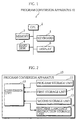
- FIG. 1 shows the hardware construction of a program conversion apparatus 10 in Embodiment 1.
- the program conversion apparatus 10 is a general-purpose computer including a CPU 2, a memory 3, a hard disk 4, a keyboard 5, and a display 6.
- the memory 3 stores a software program.
- the CPU executes the program to achieve the functions shown in FIG. 2.
- FIG. 2 is a functional block diagram showing the construction of the program conversion apparatus 10 in terms of the functions.
- the program conversion apparatus 10 includes a program storage unit 11, a first storage unit 12, a second storage unit 13, a machine-language instruction storage unit 14, and a conversion unit 15.
- the program storage unit 11 stores a program input to the program conversion apparatus 10 from outside.
- FIG. 3 shows an example of a program stored in the program storage unit 11.
- the program is written in an assembly language.
- the program includes instructions which are each composed of one operation and two operands.
- MOV and CMP are operations.
- Operands indicate numeral values or registers dealt with in operations of the CPU 2.
- the first operand is called a source operand and the second operand is called a destination operand.
- MOV R0,R1 MOV is an operation, R0 a source operand, and R1 a destination operand. This instruction indicates an operation of transferring a value from register R0 to register R1.
- FIG. 4 shows operations indicated by each instruction in the program.
- the first storage unit 12 stores operations with corresponding machine-language operation codes.
- the machine-language operation codes are referred to as op codes.
- the second storage unit 13 stores the same operations as the first storage unit 12, and also stores corresponding op codes which have different bit patterns from those of the op codes in the first storage unit 12.
- the op codes stored in the first storage unit 12 are referred to as type-1 op codes
- the op codes stored in the second storage unit 13 are referred to as type-2 op codes.
- Each one of the type-1 and type-2 op codes is composed of 12 bits.
- FIG. 5 shows specific relationships between the type-1 op codes and the type-2 op codes.
- the column 31 shows operations
- the column 32 shows type-1 op codes
- the column 33 shows type-2 op codes. These elements in the same row correspond to each other.
- two type-1 and type-2 op codes corresponding to an operation have different bit patterns.
- the first storage unit 12 stores the operations shown in the column 31 and the type-1 op codes shown in the column 32 by corresponding the operations to the type-1 op codes.
- the second storage unit 13 stores the operations shown in the column 31 and the type-2 op codes shown in the column 33 by corresponding the operations to the type-2 op codes.
- the machine-language instruction storage unit 14 accumulates and stores the machine-language instruction sequences output from the conversion unit 15.
- FIG. 6 shows examples of machine-language instruction sequences stored in the machine-language instruction storage unit 14. These examples correspond to the instructions contained in the program shown in FIG. 3.
- the operands in the program on the left-hand column are used as the operand codes in the corresponding machine-language instruction sequences.
- each operand code is a sequence of, for example, 5 bits.
- R0 and R1 in "R0,R1" in reality therefore are, for example, "00000” and "00001", respectively.
- each machine-language instruction sequence contains a type-1 or type-2 op code alternatively to shorten the Hamming distance between successive machine-language instructions.
- the conversion unit 15 reads out instructions one at a time starting from the first instruction of the program stored in the program storage unit 11, converts the read-out instructions, and stores the converted instructions into the machine-language instruction storage unit 14.
- the conversion unit 15 separately performs the conversion from an operation to an op code and the conversion from an operand to an operand code.
- the conversion unit 15 first reads out the type-1 and type-2 op codes corresponding to the conversion-target operation respectively from the first storage unit 12 and the second storage unit 13, then selects one out of the read-out op codes which renders the Hamming distance from the preceding instruction shorter.
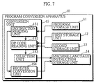
- FIG. 7 is a block diagram showing a detailed construction of the conversion unit 15.
- the conversion unit 15 includes an instruction reading unit 151, an op code reading unit 152, a selection unit 153, and a register conversion unit 154.
- the instruction reading unit 151 reads out instructions one at a time from the program storage unit 11, outputs the operations contained in the read-out instructions to the op code reading unit 152, and outputs the operands contained in the read-out instructions to the register conversion unit 154.
- the instruction reading unit 151 When the program storage unit 11 currently stores, for example, the program shown in FIG. 3, the instruction reading unit 151 first reads out "MOV R0,R1", then “CMP R1,R2", and so on in the shown order. Paralleling the sequential read-out of the instructions, the instruction reading unit 151 outputs the operation "MOV” and the operands "R0,R1” contained in the read-out "MOV R0,R1" to the op code reading unit 152 and the register conversion unit 154, respectively. Then, similarly, the instruction reading unit 151 outputs the operation "CMP” and the operands "R1,R2" contained in the read-out "CMP R1,R2" to the op code reading unit 152 and the register conversion unit 154, respectively.
- the op code reading unit 152 reads out the type-1 and type-2 op codes corresponding to the operation read out by the instruction reading unit 151 respectively from the first storage unit 12 and the second storage unit 13, then outputs the read-out op codes to the selection unit 153.
- the op code reading unit 152 reads out the type-1 op code "111000000001" from the first storage unit 12 and reads out the type-2 op code "101000000000” from the second storage unit 13 (refer to FIG. 5), and outputs these op codes to the selection unit 153.
- the selection unit 153 selects an op code, which renders the Hamming distance from the preceding instruction shorter, out of the type-1 op code and the type-2 op code read out by the op code reading unit 152, and stores the selected op code into the machine-language instruction storage unit 14.
- the selection unit 153 always selects the type-2 op code in correspondence to the operation of the first instruction in the program. Note also that the selection unit 153 always selects the type-2 op code when the type-1 op code and the type-2 op code render the Hamming distance the same. In the above two cases, the selection unit 153 may always select the type-1 op code instead of the type-2 op code.
- the register conversion unit 154 when having received an operand or a label from the instruction reading unit 151, converts the received operand or label to a binary number indicating a register number or corresponding to the label.
- the register conversion unit 154 then stores the converted binary operand code or label into the machine-language instruction storage unit 14 by corresponding it to the op code having been stored therein by the selection unit 153.
- FIG. 8 shows a detailed construction of the selection unit 153.
- the selection unit 153 includes a candidate preserving unit 1531, a pre-op code preserving unit 1532, a calculating unit 1533, a decision unit 1534, and a selector 1535.
- the candidate preserving unit 1531 has a buffer that can store two op codes, and stores in it the type-1 op code and the type-2 op code input from the op code reading unit 152.
- the candidate preserving unit 1531 updates the buffer each time the op code reading unit 152 sends new type-1 and type-2 op codes by overwriting the old op codes with the new ones.
- the pre-op code preserving unit 1532 has a buffer that can store one op code, and stores in it one code sent from the candidate preserving unit 1531 via the selector 1535.
- the pre-op code preserving unit 1532 updates the buffer each time the candidate preserving unit 1531 sends a new op code by overwriting the old op code with the new one.
- the op code preserved by the pre-op code preserving unit 1532 corresponds to an instruction that precedes the instruction corresponding to the type-1 and type-2 op codes preserved by the candidate preserving unit 1531.
- pre-op code preserved by the pre-op code preserving unit 1532, or the op code having been selected immediately before the current selection candidates, the type-1 and type-2 op codes preserved by the candidate preserving unit 1531, is referred to as pre-op code.
- the calculating unit 1533 calculates d1 which is the Hamming distance between the type-1 op code preserved by the candidate preserving unit 1531 and the pre-op code, calculates d2 which is the Hamming distance between the type-2 op code preserved by the candidate preserving unit 1531 and the pre-op code, and outputs the obtained Hamming distances d1 and d2 to the decision unit 1534.
- the calculating unit 1533 calculates the Hamming distance between two op codes as follows. The calculating unit 1533 first calculates the exclusive-OR for two values of the same digit in the two op code for each digit of the op code.
- the calculating unit 1533 calculates the sum of the results of the exclusive-ORs for each digit of the op code.
- the sum shows the number of digits having different values in the two op codes. The number is used as the Hamming distance.
- the decision unit 1534 compares the Hamming distance d1 with the Hamming distance d2 to decide which is shorter.
- the decision unit 1534 converts the decision result to a selection signal and outputs the selection signal to the selector 1535.
- the selection signal is 0 when the Hamming distance d1 is shorter than d2, and 1 when the Hamming distance d2 is shorter than d1.
- the decision unit 1534 outputs 1 as the selection signal when the Hamming distances d1 and d2 are the same or when the type-1 and type-2 op codes as the candidates for selection correspond to the first instruction in the program. In the above two case, the decision unit 1534 may always output 0 as the selection signal instead of 1.
- the selector 1535 selects one of the type-1 and type-2 op codes preserved by the candidate preserving unit 1531 according to the selection signal output from the decision unit 1534, and outputs the selected op code to the machine-language instruction storage unit 14 and the pre-op code preserving unit 1532. More specifically, the selector 1535 selects the type-1 op code when it receives 0 as the selection signal and selects the type-2 op code when it receives 1, and outputs the selected op code to the machine-language instruction storage unit 14 and the pre-op code preserving unit 1532.
- the selection unit 153 selects one out of the type-1 and type-2 op codes that renders the Hamming distance between the op codes of the successive machine-language instructions shorter, and stores the selected op code into the machine-language instruction storage unit 14. As this process is repeated, the machine-language instruction storage unit 14 accumulates the op codes received from the selector, or the op codes which render the Hamming distances between the op codes of the successive machine-language instructions.
- FIG. 9 is a flowchart showing the operation procedure of the program conversion apparatus 10.
- the instruction reading unit 151 reads out "MOV R0,R1" being the first instruction in the program from the program storage unit 11 (step 90).
- the instruction reading unit 151 then outputs operation "MOV” to the op code reading unit 152, and outputs operands "R0,R1” to the register conversion unit 154.
- the register conversion unit 154 converts the received operands "R0,R1” into operand codes. The operation of the register conversion unit 154 is not detailed here since it is the same as conventional techniques.
- the op code reading unit 152 reads out the type-1 and type-2 op codes corresponding to the operation "MOV" respectively from the first storage unit 12 and the second storage unit 13.
- the selection unit 153 converts the operation "MOV” into the type-2 op code "101000000000” since the operation corresponds to the first instruction (step 91).
- the selected type-2 op code "101000000000” is output to the machine-language instruction storage unit 14 and the pre-op code preserving unit 1532 (step 92). Following this output, the register conversion unit 154 stores the converted operand code or label into the machine-language instruction storage unit 14.
- the instruction reading unit 151 reads out the next instruction, "CMP R1,R2" from the program storage unit 11 (step 93).
- the instruction reading unit 151 then outputs operation "CMP” to the op code reading unit 152, and outputs operands "R1,R2" to the register conversion unit 154.
- the register conversion unit 154 converts the received operands "R1,R2" into operand codes.
- the op code reading unit 152 reads out type-1 op code "101000000001” and type-2 op code "111000000000” corresponding to the operation "CMP" from the first storage unit 12 and the second storage unit 13, respectively, and outputs the read-out op codes to the selection unit 153 (step 94). These op codes are preserved by the candidate preserving unit 1531 in the selection unit 153.
- the calculating unit 1533 of the selection unit 153 obtains the Hamming distance d1 by calculation from the type-1 op code "101000000001" (CMP) preserved by the candidate preserving unit 1531 and the pre-op code "101000000000” (MOV) preserved by the pre-op code preserving unit 1532.
- the calculating unit 1533 also obtains the Hamming distance d2 by calculation from the type-2 op code "111000000000” (CMP) and the pre-op code "101000000000” (MOV) (step 95). In this case, the Hamming distance d1 is 1, and the Hamming distance d2 is also 1.
- the decision unit 1534 compares the Hamming distance d1 with the Hamming distance d2 to decide which is lower (step 96).
- the decision unit 1534 therefore outputs 1 as the selection signal to the selector 1535.
- the selector 1535 Upon receiving 1 as the selection signal, the selector 1535 outputs type-2 op code "111000000000" (CMP) to the machine-language instruction storage unit 14 and the pre-op code preserving unit 1532 (step 98).
- CMP type-2 op code
- the type-1 op code is selected when d1 ⁇ d2
- the type-2 op code is selected when d1 ⁇ d2 or when the corresponding instruction is the first instruction of the program, and the selected op code is output to the machine-language instruction storage unit 14 and the pre-op code preserving unit 1532.
- the conversion unit 15 repeats the above-described procedure until the instruction reading unit 151 does not find any instruction to read. That is to say, conversion of each instruction into a machine-language instruction is repeated until all the instructions are converted into machine-language instructions (step 99).
- the program conversion apparatus 10 converts a program into machine-language instruction sequences so that the Hamming distance between op codes of the successive machine-language instructions is reduced. With such shorter Hamming distances, current changes on the instruction buses decrease when the processor reads the converted machine-language instructions from the program memory for execution. This provides an effect of reduction in the power consumption.
- FIG. 11 is a functional block diagram showing the construction of a program conversion apparatus 20 in Embodiment 2 in terms of the functions.
- the program conversion apparatus 20 includes a program storage unit 11, a first storage unit 12, a second storage unit 13, a machine-language instruction storage unit 14, and a conversion unit 25.
- the program conversion apparatus 20 includes the conversion unit 25 while the program conversion apparatus 10 includes the conversion unit 15.
- the conversion unit 25 includes an instruction reading unit 151, an op code reading unit 152, a candidate generating unit 253, a selection unit 254, and a register conversion unit 154.
- the conversion unit 25 differs from the conversion unit 15 in Embodiment 1 in that it includes the candidate generating unit 253 and the selection unit 254. The following description will be focused on the difference between Embodiment 1 and Embodiment 2.
- the candidate generating unit 253 stores the type-1 and type-2 op codes read out and output by the op code reading unit 152 into an internal memory of the candidate generating unit 253.
- type-1 or type-2 op code is selected for each operation to generate machine-language instruction sequences
- the possible combinations are regarded as candidates.
- the candidate generating unit 253 generates a plurality of such candidates alternatively.
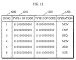
- FIG. 12 shows the content of the internal memory of the candidate generating unit 253 in correspondence to all the operations contained in the program.
- the column 1203 shows all of the operations contained in the program shown in FIG. 3.
- the column 1200 shows the identification numbers of the operations.
- the column 1201 shows the type-1 op codes corresponding to the operations shown in the column 1203.
- the column 1202 shows the type-2 op codes.
- the internal memory of the candidate generating unit 253 stores the identification numbers, type-1 op codes, and type-2 op codes respectively shown in the columns 1200, 1201, and 1202 by corresponding them to each other.
- the candidate generating unit 253 generates a plurality of candidates being combinations of the type-1 and type-2 op codes stored in the internal memory.
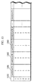
- FIG. 13 shows examples of candidates, which are combinations of the type-1 and type-2 op codes, generated by the candidate generating unit 253.
- the column 1300 shows identification numbers which correspond to the identification numbers of all the operations shown in FIG. 12.
- Each of the columns 1301, 1302, 1303, ... shows a candidate, or a combination of the type-1 and type-2 op codes for the entire machine-language instruction sequences.
- "1" indicates the type-1 op code
- "2" indicates the type-2 op code.
- the column 1301, for example, shows the candidate 1 which is composed of only the type-1 op codes.
- the column 1302 shows the candidate 2 which is composed of the type-1 op codes corresponding to the operations 1 to 5 and the type-2 op code corresponding to the operation 6.
- the candidate generating unit 253 generates a plurality of candidates for op code sequences.
- the number of the candidates generated by the candidate generating unit 253 may be determined previously (e.g., the maximum number is set to 20), or may be the number of all possible combinations of the type-1 and type-2 op codes.
- the selection unit 254 selects one among the plurality of candidates generated by the candidate generating unit 253 that includes the least number of bit changes, where the bit change is a change between successive values in the same digit in the vertically arranged binary numbers.
- the selection unit 254 stores the selected candidate into the machine-language instruction storage unit 14.
- FIG. 14 is a flowchart showing the procedure of the selection unit 254.
- the selection unit 254 calculates d1 which is a sum of the Hamming distances in terms of the op code sequences in the candidate 1 (step 1401). Hereinafter, the sum is referred to as a total Hamming distance.
- the selection unit 254 stores the total Hamming distance d1 as d (step 1402).
- the steps 1402 to 1407 are repeated for each candidate by increasing a variable c indicating the candidate number in such a way as 2, 3, 4, ...
- the selection unit 254 calculates d2 which is a total Hamming distance in terms of the op code sequences in the candidate 2 (step 1404).
- the selection unit 254 compares the total Hamming distance d2 with d to decide which is lower.
- the selection unit 254 stores d2 as d.
- the selection unit 254 calculates the total Hamming distances in terms of the op code sequences for each candidate and decides which candidate has the lowest total Hamming distance.
- the op code sequences corresponding to the candidate number N i.e., the op code sequences corresponding to the shortest Hamming distance
- the program conversion apparatus 20 generates a plurality of candidates in terms of op code sequences for the entire machine-language instruction sequences, where each candidate is composed of op codes which are each either the type-1 or the type-2.
- the program conversion apparatus 20 decides one candidate (op code sequences) having the lowest number of digit-bit changes. With this construction, current changes on the instruction buses decrease when the processor reads the converted machine-language instructions including the op code sequences with less bit changes from the program memory for execution. This provides an effect of reducing the power consumption.
- the program conversion apparatus in Embodiment 3 selects one of the two types of operand codes for each register number so that the machine-language instruction sequences have less bit changes, where the bit change is a change between successive values in the same digit in the vertically arranged binary numbers.
- FIG. 15 is a functional block diagram showing the construction of a program conversion apparatus 30 in Embodiment 3 in terms of the functions.
- the program conversion apparatus 30 includes a program storage unit 11, a first storage unit 32, a second storage unit 33, a machine-language instruction storage unit 14, and a conversion unit 35.
- the conversion unit 35 includes an instruction reading unit 351, an operand code reading unit 352, a selection unit 353, and an op code conversion unit 354.
- Embodiment 1 The following description will be focused on the components different from Embodiment 1 and the components with the same reference numbers as Embodiment 1 will not be described.
- the first storage unit 32 stores register numbers and operand codes by corresponding them to each other.
- the operand codes stored in the first storage unit 32 are referred to as type-1 operand codes.
- the second storage unit 33 stores the same register numbers as the first storage unit 32 and also stores operand codes that have different bit patterns from the type-1 operand codes, where the register numbers correspond to the operand codes.
- the operand codes stored in the second storage unit 33 are referred to as type-2 operand codes.
- the instruction reading unit 351 reads out instructions one at a time from the program storage unit 11, outputs operations contained in the read-out instructions to the op code conversion unit 354, and outputs operands contained in the read-out instructions to the operand code reading unit 352.
- the operand code reading unit 352 upon receipt of an operand from the instruction reading unit 351, reads out the type-1 and type-2 operand codes corresponding to the received operand, and outputs the read-out op codes to the selection unit 353.
- the selection unit 353 selects an operand code, which renders the Hamming distance from the preceding operand code shorter, out of the type-1 operation code and the type-2 operation code read out by the operation code reading unit 352, and outputs the selected operation code to the machine-language instruction storage unit 14.
- the operation code reading unit 352 and the selection unit 353 repeat the above-described processes as many times as there are operands per one instruction.
- the op code conversion unit 354 contains a table which shows correspondence between operations and op codes.
- the op code conversion unit 354 converts the operations received from the operation code reading unit 352 into corresponding op codes by referring to the table, and outputs the op codes to the machine-language instruction storage unit 14.
- FIG. 16 shows a detailed construction of the selection unit 353.
- the selection unit 353 includes a candidate preserving unit 3531, a pre-operand code preserving unit 3532, a calculating unit 3533, a decision unit 3534, and a selector 3535.
- the candidate preserving unit 3531 stores the type-1 operand code and the type-2 operand code input from the operand code reading unit 352.
- the pre-operand code preserving unit 3532 has a buffer that can store one operand code, and stores in it one operand code sent from the candidate preserving unit 3531 via the selector 3535.
- the pre-operand code preserving unit 3532 updates the buffer each time the candidate preserving unit 3531 sends a new operand code by overwriting the old operand code with the new one.
- the operand code preserved by the pre-operand code preserving unit 3532 is referred to as pre-operand code.
- the calculating unit 3533 calculates d1 which is the Hamming distance between the type-1 operand code preserved by the candidate preserving unit 3531 and the pre-operand code, calculates d2 which is the Hamming distance between the type-2 operand code preserved by the candidate preserving unit 3531 and the pre-operand code, and outputs the obtained Hamming distances d1 and d2 to the decision unit 3534.
- the decision unit 3534 compares the Hamming distance d1 with the Hamming distance d2 to decide which is shorter.
- the decision unit 3534 converts the decision result to a selection signal and outputs the selection signal to the selector 3535.
- the selection signal is 0 when the Hamming distance d1 is shorter than d2, and 1 when the Hamming distance d2 is shorter than d1.
- the selection signal is 0 (or 1) when the Hamming distance d1 is equal to d2.
- the selector 3535 selects one of the type-1 and type-2 operand codes preserved by the candidate preserving unit 3531 according to the selection signal output from the decision unit 3534, and stores the selected operand code into the machine-language instruction storage unit 14. More specifically, the selector 3535 selects the type-1 op code when it receives 0 as the selection signal and selects the type-2 op code when it receives 1, and outputs the selected op code to the machine-language instruction storage unit 14.
- the machine-language instruction storage unit 14 accumulates the operand codes received from the selector, or the operand codes which render the Hamming distances between the successive machine-language instructions in the machine-language instruction sequences shorter.
- the selection unit 353 selects one out of the type-1 and type-2 operand codes that renders the Hamming distance between the operand codes of the successive machine-language instructions shorter, and stores the selected op code into the machine-language instruction storage unit 14, repeating this for each pair of successive instructions.
- the program conversion apparatus 30 converts a program into machine-language instruction sequences so that the Hamming distance between operand codes of the successive machine-language instructions is reduced.
- the machine-language instruction sequences have less bit changes, where the bit change is a change between successive values in the same digit in the vertically arranged binary numbers.
- current changes on the instruction buses decrease when the processor reads the converted machine-language instructions from the program memory for execution. This provides an effect of reduction in the power consumption.
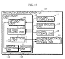
- FIG. 17 is a functional block diagram showing the construction of a program conversion apparatus 40 in Embodiment 4 in terms of the functions.
- the program conversion apparatus 40 differs from the program conversion apparatus 10 shown in FIG. 7 in that it has an op code reading unit 191 instead of the op code reading unit 152, and has an replacing unit 192 between the register conversion unit 154 and the machine-language instruction storage unit 14.
- the op code reading unit 191 has the features of the op code reading unit 151 and additionally has functions of detecting an instruction which includes both a source operand and a destination operand, and notifying the replacing unit 192 of the detection. More specifically, the op code reading unit 191 prestores operations each of which is included in an instruction that includes both a source operand and a destination operand. The op code reading unit 191 outputs a detection signal to the replacing unit 192 when the operation output from the op code reading unit 151 matches any of the operations stored in the op code reading unit 191.
- the replacing unit 192 replaces the source operand code and the destination operand code received from the register conversion unit 154 with each other for alternate inputs of the detection signal, or in other words, every two times it receives, with the same timing as the two operand codes, the detection signal from the op code reading unit 191.
- the replacing unit 192 stores the two operand codes into the machine-language instruction storage unit 14 by corresponding them to an op code.
- the replacing unit 192 performs the replacement of operand codes for alternate inputs of the detection signal which, in case of the example shown in FIG. 20, correspond to the operands CMP on the second row and ADD on the fourth row. More specifically, when R1,R2 and R3,R4 are originally to be converted into operand codes "00001 00010” and "00011 00100", respectively, the operand codes after replacement are "00010 00001” and "00100 00011", respectively.
- the replacing unit 192 stores the operand codes into the machine-language instruction storage unit 14 as they are when it does not perform such a replacement of the operand codes.
- FIG. 21 includes the column 2201 which shows the operand codes stored in the machine-language instruction storage unit 14 after the above replacement is performed.
- the places where a digit-bit change occurs are encircled.
- the number of the digit-bit changes, or the Hamming distance is 6.
- the Hamming distance is 14.
- the operand codes in the column 2201 have less digit-bit changes than column 2202.
- the program conversion apparatus 40 converts a program into machine-language instruction sequences so that the machine-language instruction sequences have less bit changes in both op code sequences and operation code sequences by performing the replacement of the operand codes, where the bit change is a change between successive values in the same digit in the vertically arranged binary numbers.
- a processor which executes machine-language instruction sequences containing type-1 and type-2 op codes will be described.
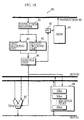
- FIG. 18 is a block diagram showing the construction of the processor in the present embodiment.
- a processor 50 includes a ROM 81, a program counter (hereinafter referred to as PC) 82, an instruction register 83, a first decoding unit 84, a second decoding unit 85, a control unit 86, an ALU 87, and a register 88.
- the processor 50 also includes an instruction bus 89, a bus 90, and a bus 91.
- the ROM 81 stores machine-language instruction sequences.
- the machine-language instruction sequences contain type-1 and type-2 op codes. Note that each of the type-1 and type-2 op codes has the same length.
- the PC 82 indicates an address of a machine-language instruction to be read out next from the ROM 81.
- the instruction register 83 stores a machine-language instruction which is read from a location in the ROM 81 specified by the address indicated by the PC 82 and is sent via the instruction bus 89.
- the first decoding unit 84 decodes the machine-language instruction stored in the instruction register 83 when the instruction includes a type-1 op code.
- the second decoding unit 85 decodes the machine-language instruction stored in the instruction register 83 when the instruction includes a type-2 op code.
- the first decoding unit 84 and the second decoding unit 85 output the same decoding result when the target op codes correspond to the same operation though the op codes have different types.
- the control unit 86 executes instructions in accordance with the decoding results output from the first decoding unit 84 and the second decoding unit 85.
- the ALU 87 performs arithmetic logic operations under control of the control unit 86.
- the register 88 has a plurality of 32-bit registers which are used by the control unit 86.
- FIG. 22 shows the bit changes in the op code sequences of the machine-language instruction sequences shown in FIG. 10 passing through the instruction bus 89.
- the instruction bus 89 is composed of 32 signal lines.
- signal lines 1 to 12 of the 32 signal lines are used.
- the signal line 1 corresponds to the most significant bit of the op code
- the signal line 12 corresponds to the least significant bit.
- FIG. 22 shows the bit pattern changes in each of the signal lines 1 to 12.
- the power is consumed at the edge a bit pattern (i.e., a succession of the same bit) where the bit value changes from 0 to 1 or from 1 to 0.
- the amount of the power consumption when one machine-language instruction is read from the ROM 81 and output to the instruction register 83 is proportionate to the sum of the number of bit changes in each signal line. That means the less number of bit changes the signal lines have, the smaller the power consumption is.
- the op code sequences shown in FIG. 22 are a mixture of type-1 op codes and type-2 op codes, with the sum of the number of bit changes (Hamming distance) being as low as 9, resulting in small power consumption.
- FIG. 23 also shows the bit changes in the op code sequences of the machine-language instruction sequences passing through the instruction bus 89, but the op code sequences are made of only type-2 op codes.
- the sum of the Hamming distances is 13, which means more power is consumed than the op code sequences shown in FIG. 22.
- the processor 50 can execute machine-language instruction sequences containing type-1 and type-2 op codes, which results in less power consumption by the instruction bus 89 when instructions are read from the ROM 81 for execution.
- the first decoding unit 84 and the second decoding unit 85 decode the type-1 op codes and the type-2 op codes generated by the program conversion apparatus 10 or 20.
- a processor 60 which executes machine-language instruction sequences containing two types of operand codes will be described.
- the processor 60 differs from the processor 50 shown in FIG. 18 in the functions of the first decoding unit 84 and the second decoding unit 85.
- the first decoding unit 84 of the present embodiment decodes the op code of the machine-language instruction stored in the instruction register 83.
- the first decoding unit 84 also decodes the operand code of the same machine-language instruction when the operand code is the type-1.
- the second decoding unit 85 decodes the operand code of the machine-language instruction stored in the instruction register 83 when the operand code is the type-2.
- the first decoding unit 84 decodes the op code and the type-1 operand code
- the second decoding unit 85 decodes the type-2 operand code.
- the processor 60 can execute machine-language instruction sequences containing type-1 and type-2 operand codes, which results in less power consumption by the instruction bus 89 when instructions are read from the ROM 81 for execution.
- the first decoding unit 84 and the second decoding unit 85 decode the type-1 operand codes and the type-2 operand codes stored in the first storage unit 32 and the second storage unit 33.
- a processor 70 which executes machine-language instruction sequences by replacing source operand codes and destination operand codes with each other will be described.
- the processor 70 differs from the processor 50 shown in FIG. 18 in that is has a replacing unit between (a) the instruction register 83 and (b) the first decoding unit 84 and the second decoding unit 85.
- the replacing unit judges whether an instruction stored in the instruction register 83 includes both a source operand and a destination operand, and replaces the source operand code and the destination operand code with each other every two times it judges so, and outputs the operand codes to the first decoding unit 84 and the second decoding unit 85.
- the processor 70 can execute machine-language instruction sequences by replacing source operand codes and destination operand codes with each other, which results in less power consumption by the instruction bus 89 when instructions are read from the ROM 81 for execution.
Landscapes
- Engineering & Computer Science (AREA)
- Theoretical Computer Science (AREA)
- General Engineering & Computer Science (AREA)
- Software Systems (AREA)
- Physics & Mathematics (AREA)
- General Physics & Mathematics (AREA)
- Devices For Executing Special Programs (AREA)
- Executing Machine-Instructions (AREA)
Abstract
Description
- The present invention relates to a program conversion apparatus which converts a source program into a machine-language sequence, and relates to a processor which executes the machine-language sequence output from the program conversion apparatus.
- A program conversion apparatus has a table showing relationships between (a) instructions written in a programming language such as a high-level language and an assembly language and (b) machine-language instructions. When a source program is input to the program conversion apparatus, the program conversion apparatus converts the source program into machine-language instruction sequences using the table.
- A processor stores the machine-language instruction sequences in a ROM, reads out the machine-language instruction sequences sequentially in units of machine-language instructions from the ROM to an instruction register, decodes the instructions, and allow the components such as an ALU and a register to operate in accordance with the decoding results.
- Buses contained in the processor are each composed of a plurality of signal lines. Power is consumed when a bit value passing through a signal line changes from 0 to 1 or from 1 to 0. Each signal line corresponds to one digit of the machine-language instructions. That means the more bit changes are included in the machine-language instruction sequences, the more power is consumed, where the bit change is a change between successive values in the same digit between two successive machine-language instructions. Accordingly, there has been a desire to reduce the number of bit changes in the machine-language instruction sequences to reduce the power consumption.
- It is therefore an object of the present invention to provide a program conversion apparatus which converts a source program into machine-language instruction sequences having reduced number of bit changes, where the bit change is a change between values in the same digit between two successive machine-language instructions, a record medium recording a program for achieving the conversion, a processor for executing the converted machine-language instruction sequences, and a record medium recording a program for achieving the execution.
- The above object is fulfilled by a program conversion apparatus for converting a source program into machine-language instructions to be executed by a processor, the processor reading out the machine-language instructions sequentially from a memory unit via a bus, the program conversion apparatus comprising:
- a program storage means for storing the source program which includes a plurality of instructions, each instruction including one or more types of components; a machine-language storage means for storing a plurality of sets of two or more types of machine-language codes which correspond to a plurality of components of a predetermined type included in the plurality of instructions, the two or more types of machine-language codes in each set having different bit patterns; and a conversion means for converting the plurality of instructions stored in the program storage means into the machine-language instructions, wherein the conversion means converts each of the plurality of predetermined-type components selectively into one of the two or more types of machine-language codes so that changes in logical states of signal lines composing the bus are fewest for the machine-language instructions.
-
- With the above construction, the program conversion apparatus converts a source program into machine-language instruction sequences that render the power consumption of a processor small. The machine-language instruction sequences have reduced number of bit changes, where the bit change is a change between values in the same digit between two successive machine-language instructions. This enables the processor to execute the machine-language instructions with less power consumption since when these instructions pass through the bus between the ROM and the instruction register bus, less power is consumed due to less bit changes (power consumption) in each signal line constituting the bus.
- In the above program conversion apparatus, each of the plurality of predetermined-type components may indicate an operation, the machine-language storage means stores a plurality of sets of two types of operation codes corresponding to the plurality of predetermined-type components indicating operations, the two types of operation codes in each set having different bit patterns, and the conversion means converts each of the plurality of predetermined-type components selectively into one of the two types of operation codes so that changes in logical states of signal lines composing the bus are fewest for the machine-language instructions.
- With the above construction, the program conversion apparatus converts a source program into machine-language instruction sequences that render the power consumption of a processor small. The machine-language instruction sequences have reduced number of bit changes in terms of the operation codes. This enables the processor to execute the machine-language instructions with less power consumption since when these instructions pass through the bus between the ROM and the instruction register bus, less power is consumed due to less bit changes (power consumption) in each signal line constituting the bus.
- In the above program conversion apparatus, each digit of the machine-language instructions may correspond to one of the signal lines, the conversion means converts the plurality of instructions included in the source program one by one, and includes: a reading means for reading out the plurality of sets of two types of operation codes corresponding to the plurality of predetermined-type components; a calculation means for comparing, for each of the two types of operation codes in a set read by the reading means, a bit pattern of the operation code with bits in a corresponding position in an immediately preceding machine language instruction and calculating a number of bits in the bit pattern having different values from the immediately preceding machine language instruction; a judging means for judging which of the two types of operation code has a bit pattern with a lower number of different bit values; and a selecting means for selecting an operation code judged to have the bit pattern with the lower number of different bit values.
- With the above construction, the program conversion apparatus converts a plurality of certain components of a source program into operation codes having short Hamming distances from the preceding operation codes, sequentially starting from the first component of the program. As a result, the machine-language instruction sequences converted from the source program have less bit changes in terms of the operation codes. This enables the processor to execute the machine-language instructions with less power consumption for the same reason stated earlier. It should be noted here that the Hamming distance is the sum of bit changes between two bit patterns having the same length, the bit change being a change between two values in the same digit. For example, between bit patterns "10011" and "10110", there are bit changes in the third and fifth digits from left. In this case, the Hamming distance is 2.
- In the above program conversion apparatus, the calculation means may include: an exclusive OR means for performing an exclusive OR for each digit between each of the two types of operation code in a set read by the reading means and the bits in the corresponding position in the immediately preceding machine language instruction; and an addition means for adding up each result of the exclusive OR means to obtain a sum for each of the two types of operation code, the sums being used as the number of bits in the bit pattern having different values from the immediately preceding machine language instruction.
- With the above construction, it is possible to obtain the Hamming distance between two operation codes simply by calculating an exclusive OR for each digit in each of the two combinations of the operation codes and adding up the results for each code.
- In the above program conversion apparatus, bit patterns that render the sum of the number of digit-value changes lower than a threshold value may be assigned to machine-language codes in the machine-language storage means that correspond to two predetermined components which have a high probability of being included in two successive instructions in the source program.
- With the above construction, the number of digit-value changes in the entire machine-language instructions is reduced.
- In the above program conversion apparatus, each digit of the machine-language instructions may correspond to one of the signal lines, the conversion means includes: a reading means for reading out the plurality of sets of two types of operation codes corresponding to the plurality of predetermined-type components from the machine-language storage means; a candidate generating means for generating a plurality of candidates which are different combinations of operation codes each of which is selected from each set of the two types of operation code; and a selection means for selecting one of the plurality of candidates that renders changes in values of the machine-language instructions passing through signal lines of the bus the smallest.
- With the above construction, the conversion means can convert the source program into machine-language instructions having less digit-value changes by selecting one among a plurality of candidates.
- In the above program conversion apparatus, the selection means may include: a calculation means for calculating the number of digit-value changes between each two successive operation codes in each of the plurality of candidates, and obtains a sum of the number of digit-value changes for each of the plurality of candidates; a judging means for judging which sum is the lowest; and a selection unit for selecting one of the plurality of candidates that corresponds to the sum judged by the judging means as the lowest.
- With the above construction, the selection means can select one candidate that has the least number of digit-value changes by calculating the Hamming distance between each two successive operation codes and comparing the calculated Hamming distances.
- In the above program conversion apparatus, each of the plurality of predetermined-type components may indicate a resource, the machine-language storage means stores a plurality of sets of two types of operand codes corresponding to the plurality of predetermined-type components indicating resources, the two types of operand codes in each set having different bit patterns, and the conversion means converts each of the plurality of predetermined-type components selectively into one of the two types of operand codes so that changes in logical states of signal lines composing the bus are fewest for the machine-language instructions.
- With the above construction, the program conversion apparatus converts a source program into machine-language instruction sequences that render the power consumption of a processor small. The machine-language instruction sequences have reduced number of bit changes in terms of the operand codes. This enables the processor to execute the machine-language instructions with less power consumption since when these instructions pass through the bus between the ROM and the instruction register bus, less power is consumed due to less bit changes (power consumption) in each signal line constituting the bus.
- In the above program conversion apparatus, each digit of the machine-language instructions may correspond to one of the signal lines, the conversion means converts the plurality of instructions included in the source program one by one, and includes: a reading means for reading out the plurality of sets of two types of operand codes corresponding to the plurality of predetermined-type components; a calculation means for comparing, for each of the two types of operand codes in a set read by the reading means, a bit pattern of the operand code with bits in a corresponding position in an immediately preceding machine language instruction and calculating a number of bits in the bit pattern having different values from the immediately preceding machine language instruction; a judging means for judging which of the two types of operand code has a bit pattern with a lower number of different bit values; and a selecting means for selecting an operand code judged to have the bit pattern with the lower number of different bit values.
- With the above construction, the program conversion apparatus converts a plurality of certain components of a source program into operand codes having short Hamming distances from the preceding operand codes, sequentially starting from the first component of the program. As a result, the machine-language instruction sequences converted from the source program have less bit changes in terms of the operand codes. This enables the processor to execute the machine-language instructions with less power consumption for the same reason stated earlier.
- In the above program conversion apparatus, the calculation means may include: an exclusive OR means for performing an exclusive OR for each digit between each of the two types of operand code in a set read by the reading means and the bits in the corresponding position in the immediately preceding machine language instruction; and an addition means for adding up each result of the exclusive OR means to obtain a sum for each of the two types of operand code, the sums being used as the number of bits in the bit pattern having different values from the immediately preceding machine language instruction.
- With the above construction, it is possible to obtain the Hamming distance between two operand codes simply by calculating an exclusive OR for each digit in each of the two combinations of the operand codes and adding up the results for each code.
- In the above program conversion apparatus, each digit of the machine-language instructions may correspond to one of the signal lines, the conversion means includes: a reading means for reading out the plurality of sets of two types of operand codes corresponding to the plurality of predetermined-type components from the machine-language storage means; a candidate generating means for generating a plurality of candidates which are different combinations of operand codes each of which is selected from each set of the two types of operand code; and a selection means for selecting one of the plurality of candidates that renders changes in values of the machine-language instructions passing through signal lines of the bus the lowest.
- With the above construction, the conversion means can convert the source program into machine-language instructions having less digit-value changes by selecting one among a plurality of candidates.
- In the above program conversion apparatus, the selection means may include: a calculation means for calculating the number of digit-value changes between each two successive operand codes in each of the plurality of candidates, and obtains a sum of the number of digit-value changes for each of the plurality of candidates; a judging means for judging which sum is the lowest; and a selection unit for selecting one of the plurality of candidates that corresponds to the sum judged by the judging means as the lowest.
- With the above construction, the selection means can select one candidate that has the least number of digit-value changes by calculating the Hamming distance between each two successive operand codes and comparing the calculated Hamming distances.
- In the above program conversion apparatus, the conversion means may further include: a setting means for inserting an identification bit into each machine-language instruction converted by the conversion means, the identification bit indicating which of the two types of machine-language codes has been selected.
- With the above construction, the processor that executes the machine-language instructions can identify the type of each instruction by referring to the identification bit.
- The above object is also fulfilled by a program conversion apparatus for converting a source program into machine-language instructions to be executed by a processor, the processor reading out the machine-language instructions sequentially from a memory unit via a bus, the program conversion apparatus comprising: a program storage means for storing the source program which includes a plurality of instructions; a conversion means for converting the plurality of instructions stored in the program storage means into the machine-language instructions; and a replacing means for, every two times the conversion means outputs a machine-language instruction including both a source field and a destination field, replacing contents of the source field and the destination field with each other.
- With the above construction, when two successive machine-language instructions are, for example, "ADD R1,R2" (add up values stored in R1 and R2 and store the result into R2), and "ADD R2,R3" (add up values stored in R2 and R3 and store the result into R3), the replacing means replaces R2 and R3 of the second instruction with each other to "ADD R3,R2". Alternatively, the replacing means replaces R1 and R2 of the first instruction with each other to "ADD R2,R1". After either of these replacements, R2 with the same bit pattern is placed at the same digit position in the two instructions, resulting in the
Hamming distance 0 between the two instructions in terms of the R2 section. - In the above program conversion apparatus, the conversion means may convert the plurality of instructions into the machine-language instructions having a fixed length, and the replacing means replaces contents of the source field and the destination field with each other every two times the replacing means detects a machine-language instruction having a register number in at least one of the source field and the destination field.
- With the above construction, the same effect as above can be obtained.
- In the above program conversion apparatus, each machine-language instruction may have a bit field, and the replacing means inserts a bit value into the bit field of a machine-language instruction when the replacing means has replaced contents of the source field and the destination field of this machine-language instruction.
- With the above construction, the processor that executes the machine-language instructions can determine whether the replacement has been performed by referring to the bit.
- In the above program conversion apparatus, the replacing means may replace contents of the source field and the destination field with each other when an alternate machine-language instruction output from the conversion means has a register number in at least one of the source field and the destination field.
- With the above construction, two successive machine-language instructions each have a section indicating a register placed at the same digit, resulting in the
Hamming distance 0 at this section. - The above object is also fulfilled by a processor comprising: a reading means for reading a plurality of machine-language instructions sequentially from a memory via a bus, each of the plurality of machine-language instructions having either type-1 bit pattern or type-2 bit pattern, and has an identification bit which indicates either the type-1 bit pattern or the type-2 bit pattern; an identification means for identifying a bit pattern of each of the plurality of machine-language instructions read out by the reading means by referring to the identification bit; a first decoding means for decoding machine-language instructions having type-1 bit patterns and outputting decoding results; and a second decoding means for decoding machine-language instructions having type-2 bit patterns and outputting decoding results, wherein the first decoding means and the second decoding means output the same decoding result for the same machine-language instruction whether a bit patter thereof is type-1 or type-2.
- With the above construction, the processor can execute the machine-language instructions that each have two bit patterns. By selectively combining the two bit patterns, the processor can execute the machine-language instructions with less power consumption since when these instructions pass through the bus between the ROM and the instruction register bus, less power is consumed due to less bit changes (power consumption) in each signal line constituting the bus.
- In the above processor, the type-1 bit pattern and the type-2 bit pattern may be different from each other in terms of a bit pattern of an operation code included in each of the plurality of machine-language instructions, and the processor further comprises: an operand decoding unit for decoding operand codes of the plurality of machine-language instructions, wherein the first decoding means decodes operation codes of machine-language instructions having the type-1 bit pattern, and the second decoding means decodes operation codes of machine-language instructions having the type-2 bit pattern.
- With the above construction, the processor can execute the machine-language instructions that each have two bit patterns in terms of the operation code section.
- In the above processor, the type-1 bit pattern and the type-2 bit pattern may be different from each other in terms of a bit pattern of an operand code included in each of the plurality of machine-language instructions, each operand code corresponding to two different bit patterns and indicating the same register, and the processor further comprises: an operation decoding unit for decoding operation codes of the plurality of machine-language instructions, wherein the first decoding means decodes operand codes of machine-language instructions having the type-1 bit pattern, and the second decoding means decodes operand codes of machine-language instructions having the type-2 bit pattern.
- With the above construction, the processor can execute the machine-language instructions that each have two bit patterns in terms of the operand code section.
- In the above processor, each machine-language instruction may be classified into an order-1 type and an order-2 type regardless of a bit pattern thereof, the order-1 type indicating an order of a plurality of operand codes included in each machine-language instruction, and the order-2 type indicating another order of the plurality of operand codes, each machine-language instruction having a classification bit indicating the order-1 type or the order-2 type, and the operand decoding unit includes: a classification unit for classifying each machine-language instruction into the order-1 type or the order-2 type by referring to the classification bit; a rearranging unit for rearranging the plurality of operand codes of machine-language instructions of the order-2 type to the order-1 type; and a decoding unit for decoding operand codes of machine-language instructions of the order-1 type and operand codes rearranged by the rearranging unit from the order-2 type to the order-1 type.
- With the above construction, the processor identifies the order type (order-1 type or order-2 type) of the operand codes by referring to the classification bit, and rearranges the operand codes of the order-2 type to the order-1 type to decode the machine-language instructions.
- The above object is also fulfilled by a processor comprising: a reading means for reading a plurality of machine-language instructions sequentially from a memory via a bus, each of the plurality of machine-language instructions has a plurality of operands, and is classified into one of an order-1 type machine-language instruction and an order-2 type machine-language instruction, the order-1 type and order-2 type machine-language instructions having different orders of the plurality of operands; an identification means for identifying each of the plurality of machine-language instructions read out by the reading means as the order-1 type or the order-2 type machine-language instruction; a first decoding means for decoding order-1 type machine-language instructions and outputting decoding results; and a second decoding means for decoding order-2 type machine-language instructions and outputting decoding results.
- With the above construction, when a machine-language instruction has, for example, a fixed length of 32 bits, the processor specifies the address of the next machine-language instruction by incrementing the program counter by four. In this case, the identification means can easily identify the type of each machine-language instruction by performing the simple judgement on whether the third bit from the least significant bit in the program counter is 0.
- In the above processor, the second decoding means may include: a rearranging unit for rearranging orders of the plurality of operand codes of order-2 type machine-language instructions, decoding the rearranged operand codes, and outputting the same decoding results as the first decoding means.
- With the above construction, the processor reads out each machine-language instruction with shorter Hamming distance from the ROM to the instruction register, and decodes it after restoring the order of the operands if the operands have been replaced with each other. This reduces the power consumption in the bus when such an instruction passes through the bus.
- These and other objects, advantages and features of the invention will become apparent from the following description thereof taken in conjunction with the accompanying drawings which illustrate a specific embodiment of the invention. In the drawings:
- FIG. 1 shows the hardware construction of a program
conversion apparatus in
Embodiment 1; - FIG. 2 is a functional block diagram showing the
construction of the
program conversion apparatus 10 in terms of the functions; - FIG. 3 shows an example of a program stored in the
program storage unit 11; - FIG. 4 shows instructions included in the program shown in FIG. 2;
- FIG. 5 shows specific examples of the relationships between type-1 op codes and type-2 op codes;
- FIG. 6 shows examples of machine-language instruction
sequences stored in the machine-language
instruction storage unit 14; - FIG. 7 is a block diagram showing a detailed
construction of the
conversion unit 15; - FIG. 8 shows a detailed construction of the
selection unit 153; - FIG. 9 is a flowchart showing the operation procedure
of the
program conversion apparatus 10; - FIG. 10 shows machine-language instruction sequences
converted by the
program conversion apparatus 10; - FIG. 11 is a functional block diagram showing the
construction of a program conversion apparatus in
Embodiment 2 in terms of the functions; - FIG. 12 shows the content of the internal memory of the
candidate generating unit 253 in correspondence to all the operations contained in the program; - FIG. 13 shows combinations of the type-1 and type-2 op
codes, generated by the
candidate generating unit 253; - FIG. 14 is a flowchart showing the procedure of the
selection unit 254; - FIG. 15 is a functional block diagram showing the
construction of a program conversion apparatus in
Embodiment 3 in terms of the functions; - FIG. 16 shows a detailed construction of the
selection unit 353; - FIG. 17 is a functional block diagram showing the
construction of a program conversion apparatus in
Embodiment 4 in terms of the functions; - FIG. 18 is a block diagram showing the construction of the processor in the present embodiment;
- FIG. 19 shows operations prestored in the op
code reading unit 191; - FIG. 20 shows examples of programs;
- FIG. 21 shows bit patterns of machine-language operands of machine-language instruction sequences stored in the machine-language instruction storage unit 14 (column 2201) and bit patterns of machine-language operands for which replacement of the operand codes has not been performed (column 2202);
- FIG. 22 shows the bit changes in the op code sequences
of the machine-language instruction sequences shown in FIG. 10
passing through the
instruction bus 89; and - FIG. 23 also shows the bit changes in the op code
sequences of the machine-language instruction sequences passing
through the
instruction bus 89, but the op code sequences are made of only type-2 op codes. -
- The following is a description of the present invention through specific embodiments thereof by way of referring to the drawings.
- The program conversion apparatus in
Embodiment 1 will be described with reference to the drawings. - FIG. 1 shows the hardware construction of a
program conversion apparatus 10 inEmbodiment 1. - As shown in FIG. 1, the
program conversion apparatus 10 is a general-purpose computer including aCPU 2, amemory 3, ahard disk 4, akeyboard 5, and adisplay 6. Thememory 3 stores a software program. The CPU executes the program to achieve the functions shown in FIG. 2. - FIG. 2 is a functional block diagram showing the construction of the
program conversion apparatus 10 in terms of the functions. - In FIG. 2, the
program conversion apparatus 10 includes aprogram storage unit 11, afirst storage unit 12, asecond storage unit 13, a machine-languageinstruction storage unit 14, and aconversion unit 15. - The
program storage unit 11 stores a program input to theprogram conversion apparatus 10 from outside. FIG. 3 shows an example of a program stored in theprogram storage unit 11. - As shown in FIG. 3, the program is written in an assembly language. The program includes instructions which are each composed of one operation and two operands.
- Here, the operations indicate operations of the
CPU 2. In FIG. 3, MOV and CMP are operations. - Operands indicate numeral values or registers dealt with in operations of the
CPU 2. In FIG. 3, Rn (n = 0, 1, 2, 3, ...) is an operand indicating a register. In each instruction including two operands, the first operand is called a source operand and the second operand is called a destination operand. For example, in instruction "MOV R0,R1", MOV is an operation, R0 a source operand, and R1 a destination operand. This instruction indicates an operation of transferring a value from register R0 to register R1. - FIG. 4 shows operations indicated by each instruction in the program.
- The
first storage unit 12 stores operations with corresponding machine-language operation codes. Hereinafter, the machine-language operation codes are referred to as op codes. - The
second storage unit 13 stores the same operations as thefirst storage unit 12, and also stores corresponding op codes which have different bit patterns from those of the op codes in thefirst storage unit 12. - Hereinafter, the op codes stored in the
first storage unit 12 are referred to as type-1 op codes, and the op codes stored in thesecond storage unit 13 are referred to as type-2 op codes. Each one of the type-1 and type-2 op codes is composed of 12 bits. - FIG. 5 shows specific relationships between the type-1 op codes and the type-2 op codes.
- In FIG. 5, the
column 31 shows operations, thecolumn 32 shows type-1 op codes, and thecolumn 33 shows type-2 op codes. These elements in the same row correspond to each other. As understood from FIG. 5, two type-1 and type-2 op codes corresponding to an operation have different bit patterns. Thefirst storage unit 12 stores the operations shown in thecolumn 31 and the type-1 op codes shown in thecolumn 32 by corresponding the operations to the type-1 op codes. Thesecond storage unit 13 stores the operations shown in thecolumn 31 and the type-2 op codes shown in thecolumn 33 by corresponding the operations to the type-2 op codes. - The machine-language
instruction storage unit 14 accumulates and stores the machine-language instruction sequences output from theconversion unit 15. - FIG. 6 shows examples of machine-language instruction sequences stored in the machine-language
instruction storage unit 14. These examples correspond to the instructions contained in the program shown in FIG. 3. In FIG. 6, the operands in the program on the left-hand column are used as the operand codes in the corresponding machine-language instruction sequences. In reality, however, each operand code is a sequence of, for example, 5 bits. R0 and R1 in "R0,R1" in reality therefore are, for example, "00000" and "00001", respectively. - As shown in FIG. 6, each machine-language instruction sequence contains a type-1 or type-2 op code alternatively to shorten the Hamming distance between successive machine-language instructions.
- The
conversion unit 15 reads out instructions one at a time starting from the first instruction of the program stored in theprogram storage unit 11, converts the read-out instructions, and stores the converted instructions into the machine-languageinstruction storage unit 14. - More specifically, the
conversion unit 15 separately performs the conversion from an operation to an op code and the conversion from an operand to an operand code. When performing the conversion from an operation to an op code, theconversion unit 15 first reads out the type-1 and type-2 op codes corresponding to the conversion-target operation respectively from thefirst storage unit 12 and thesecond storage unit 13, then selects one out of the read-out op codes which renders the Hamming distance from the preceding instruction shorter. - FIG. 7 is a block diagram showing a detailed construction of the
conversion unit 15. - As shown in FIG. 7, the
conversion unit 15 includes aninstruction reading unit 151, an opcode reading unit 152, aselection unit 153, and aregister conversion unit 154. - The
instruction reading unit 151 reads out instructions one at a time from theprogram storage unit 11, outputs the operations contained in the read-out instructions to the opcode reading unit 152, and outputs the operands contained in the read-out instructions to theregister conversion unit 154. - When the
program storage unit 11 currently stores, for example, the program shown in FIG. 3, theinstruction reading unit 151 first reads out "MOV R0,R1", then "CMP R1,R2", and so on in the shown order. Paralleling the sequential read-out of the instructions, theinstruction reading unit 151 outputs the operation "MOV" and the operands "R0,R1" contained in the read-out "MOV R0,R1" to the opcode reading unit 152 and theregister conversion unit 154, respectively. Then, similarly, theinstruction reading unit 151 outputs the operation "CMP" and the operands "R1,R2" contained in the read-out "CMP R1,R2" to the opcode reading unit 152 and theregister conversion unit 154, respectively. - The op
code reading unit 152 reads out the type-1 and type-2 op codes corresponding to the operation read out by theinstruction reading unit 151 respectively from thefirst storage unit 12 and thesecond storage unit 13, then outputs the read-out op codes to theselection unit 153. - For example, when the
instruction reading unit 151 outputs the operation "MOV", the opcode reading unit 152 reads out the type-1 op code "111000000001" from thefirst storage unit 12 and reads out the type-2 op code "101000000000" from the second storage unit 13 (refer to FIG. 5), and outputs these op codes to theselection unit 153. - The
selection unit 153 selects an op code, which renders the Hamming distance from the preceding instruction shorter, out of the type-1 op code and the type-2 op code read out by the opcode reading unit 152, and stores the selected op code into the machine-languageinstruction storage unit 14. - It should be noted here that the
selection unit 153 always selects the type-2 op code in correspondence to the operation of the first instruction in the program. Note also that theselection unit 153 always selects the type-2 op code when the type-1 op code and the type-2 op code render the Hamming distance the same. In the above two cases, theselection unit 153 may always select the type-1 op code instead of the type-2 op code. - The
register conversion unit 154, when having received an operand or a label from theinstruction reading unit 151, converts the received operand or label to a binary number indicating a register number or corresponding to the label. Theregister conversion unit 154 then stores the converted binary operand code or label into the machine-languageinstruction storage unit 14 by corresponding it to the op code having been stored therein by theselection unit 153. - FIG. 8 shows a detailed construction of the
selection unit 153. - The
selection unit 153 includes acandidate preserving unit 1531, a pre-opcode preserving unit 1532, a calculatingunit 1533, adecision unit 1534, and aselector 1535. - The
candidate preserving unit 1531 has a buffer that can store two op codes, and stores in it the type-1 op code and the type-2 op code input from the opcode reading unit 152. Thecandidate preserving unit 1531 updates the buffer each time the opcode reading unit 152 sends new type-1 and type-2 op codes by overwriting the old op codes with the new ones. - The pre-op
code preserving unit 1532 has a buffer that can store one op code, and stores in it one code sent from thecandidate preserving unit 1531 via theselector 1535. The pre-opcode preserving unit 1532 updates the buffer each time thecandidate preserving unit 1531 sends a new op code by overwriting the old op code with the new one. The op code preserved by the pre-opcode preserving unit 1532 corresponds to an instruction that precedes the instruction corresponding to the type-1 and type-2 op codes preserved by thecandidate preserving unit 1531. - Hereinafter, the op code preserved by the pre-op
code preserving unit 1532, or the op code having been selected immediately before the current selection candidates, the type-1 and type-2 op codes preserved by thecandidate preserving unit 1531, is referred to as pre-op code. - The calculating
unit 1533 calculates d1 which is the Hamming distance between the type-1 op code preserved by thecandidate preserving unit 1531 and the pre-op code, calculates d2 which is the Hamming distance between the type-2 op code preserved by thecandidate preserving unit 1531 and the pre-op code, and outputs the obtained Hamming distances d1 and d2 to thedecision unit 1534. The calculatingunit 1533 calculates the Hamming distance between two op codes as follows. The calculatingunit 1533 first calculates the exclusive-OR for two values of the same digit in the two op code for each digit of the op code. Here, when the two values are the same, the result of the exclusive-OR is 0; and when the two values are different from each other, the result of the exclusive-OR is 1. The calculatingunit 1533 then calculates the sum of the results of the exclusive-ORs for each digit of the op code. The sum shows the number of digits having different values in the two op codes. The number is used as the Hamming distance. - The
decision unit 1534 compares the Hamming distance d1 with the Hamming distance d2 to decide which is shorter. Thedecision unit 1534 converts the decision result to a selection signal and outputs the selection signal to theselector 1535. The selection signal is 0 when the Hamming distance d1 is shorter than d2, and 1 when the Hamming distance d2 is shorter than d1. - It should be noted here that the
decision unit 1534outputs 1 as the selection signal when the Hamming distances d1 and d2 are the same or when the type-1 and type-2 op codes as the candidates for selection correspond to the first instruction in the program. In the above two case, thedecision unit 1534 may alwaysoutput 0 as the selection signal instead of 1. - The
selector 1535 selects one of the type-1 and type-2 op codes preserved by thecandidate preserving unit 1531 according to the selection signal output from thedecision unit 1534, and outputs the selected op code to the machine-languageinstruction storage unit 14 and the pre-opcode preserving unit 1532. More specifically, theselector 1535 selects the type-1 op code when it receives 0 as the selection signal and selects the type-2 op code when it receives 1, and outputs the selected op code to the machine-languageinstruction storage unit 14 and the pre-opcode preserving unit 1532. - As described above, the
selection unit 153 selects one out of the type-1 and type-2 op codes that renders the Hamming distance between the op codes of the successive machine-language instructions shorter, and stores the selected op code into the machine-languageinstruction storage unit 14. As this process is repeated, the machine-languageinstruction storage unit 14 accumulates the op codes received from the selector, or the op codes which render the Hamming distances between the op codes of the successive machine-language instructions. - The operation of the
program conversion apparatus 10 having the above construction will be described. - FIG. 9 is a flowchart showing the operation procedure of the
program conversion apparatus 10. - Now, the operation of the
program conversion apparatus 10 in converting the program into machine-language instruction sequences will be described with reference to the flowchart. - The
instruction reading unit 151 reads out "MOV R0,R1" being the first instruction in the program from the program storage unit 11 (step 90). Theinstruction reading unit 151 then outputs operation "MOV" to the opcode reading unit 152, and outputs operands "R0,R1" to theregister conversion unit 154. Theregister conversion unit 154 converts the received operands "R0,R1" into operand codes. The operation of theregister conversion unit 154 is not detailed here since it is the same as conventional techniques. - The op
code reading unit 152 reads out the type-1 and type-2 op codes corresponding to the operation "MOV" respectively from thefirst storage unit 12 and thesecond storage unit 13. Theselection unit 153 converts the operation "MOV" into the type-2 op code "101000000000" since the operation corresponds to the first instruction (step 91). - The selected type-2 op code "101000000000" is output to the machine-language
instruction storage unit 14 and the pre-op code preserving unit 1532 (step 92). Following this output, theregister conversion unit 154 stores the converted operand code or label into the machine-languageinstruction storage unit 14. - The
instruction reading unit 151 reads out the next instruction, "CMP R1,R2" from the program storage unit 11 (step 93). Theinstruction reading unit 151 then outputs operation "CMP" to the opcode reading unit 152, and outputs operands "R1,R2" to theregister conversion unit 154. Theregister conversion unit 154 converts the received operands "R1,R2" into operand codes. - The op
code reading unit 152 reads out type-1 op code "101000000001" and type-2 op code "111000000000" corresponding to the operation "CMP" from thefirst storage unit 12 and thesecond storage unit 13, respectively, and outputs the read-out op codes to the selection unit 153 (step 94). These op codes are preserved by thecandidate preserving unit 1531 in theselection unit 153. - The calculating
unit 1533 of theselection unit 153 obtains the Hamming distance d1 by calculation from the type-1 op code "101000000001" (CMP) preserved by thecandidate preserving unit 1531 and the pre-op code "101000000000" (MOV) preserved by the pre-opcode preserving unit 1532. The calculatingunit 1533 also obtains the Hamming distance d2 by calculation from the type-2 op code "111000000000" (CMP) and the pre-op code "101000000000" (MOV) (step 95). In this case, the Hamming distance d1 is 1, and the Hamming distance d2 is also 1. - The
decision unit 1534 compares the Hamming distance d1 with the Hamming distance d2 to decide which is lower (step 96). - In this example, it is decided that d1 = d2. The
decision unit 1534 therefore outputs 1 as the selection signal to theselector 1535. Upon receiving 1 as the selection signal, theselector 1535 outputs type-2 op code "111000000000" (CMP) to the machine-languageinstruction storage unit 14 and the pre-op code preserving unit 1532 (step 98). - In
steps 96 to 98, the type-1 op code is selected when d1<d2, and the type-2 op code is selected when d1≧d2 or when the corresponding instruction is the first instruction of the program, and the selected op code is output to the machine-languageinstruction storage unit 14 and the pre-opcode preserving unit 1532. - The
conversion unit 15 repeats the above-described procedure until theinstruction reading unit 151 does not find any instruction to read. That is to say, conversion of each instruction into a machine-language instruction is repeated until all the instructions are converted into machine-language instructions (step 99). - As describe above, the
program conversion apparatus 10 converts a program into machine-language instruction sequences so that the Hamming distance between op codes of the successive machine-language instructions is reduced. With such shorter Hamming distances, current changes on the instruction buses decrease when the processor reads the converted machine-language instructions from the program memory for execution. This provides an effect of reduction in the power consumption. - The program conversion apparatus in
Embodiment 2 will be described. - FIG. 11 is a functional block diagram showing the construction of a
program conversion apparatus 20 inEmbodiment 2 in terms of the functions. - In FIG. 11, the
program conversion apparatus 20 includes aprogram storage unit 11, afirst storage unit 12, asecond storage unit 13, a machine-languageinstruction storage unit 14, and aconversion unit 25. Theprogram conversion apparatus 20 includes theconversion unit 25 while theprogram conversion apparatus 10 includes theconversion unit 15. - The
conversion unit 25 includes aninstruction reading unit 151, an opcode reading unit 152, acandidate generating unit 253, aselection unit 254, and aregister conversion unit 154. Theconversion unit 25 differs from theconversion unit 15 inEmbodiment 1 in that it includes thecandidate generating unit 253 and theselection unit 254. The following description will be focused on the difference betweenEmbodiment 1 andEmbodiment 2. - The
candidate generating unit 253 stores the type-1 and type-2 op codes read out and output by the opcode reading unit 152 into an internal memory of thecandidate generating unit 253. Here, when either type-1 or type-2 op code is selected for each operation to generate machine-language instruction sequences, there are a plurality of possible combinations of type-1 and type-2 op codes for the entire machine-language instruction sequences. In the present embodiment, the possible combinations are regarded as candidates. Thecandidate generating unit 253 generates a plurality of such candidates alternatively. - FIG. 12 shows the content of the internal memory of the
candidate generating unit 253 in correspondence to all the operations contained in the program. - In FIG. 12, the
column 1203 shows all of the operations contained in the program shown in FIG. 3. Thecolumn 1200 shows the identification numbers of the operations. Thecolumn 1201 shows the type-1 op codes corresponding to the operations shown in thecolumn 1203. Similarly, thecolumn 1202 shows the type-2 op codes. The internal memory of thecandidate generating unit 253 stores the identification numbers, type-1 op codes, and type-2 op codes respectively shown in thecolumns - The
candidate generating unit 253 generates a plurality of candidates being combinations of the type-1 and type-2 op codes stored in the internal memory. - FIG. 13 shows examples of candidates, which are combinations of the type-1 and type-2 op codes, generated by the
candidate generating unit 253. - In FIG. 13, the
column 1300 shows identification numbers which correspond to the identification numbers of all the operations shown in FIG. 12. Each of thecolumns column 1301, for example, shows thecandidate 1 which is composed of only the type-1 op codes. Similarly, thecolumn 1302 shows thecandidate 2 which is composed of the type-1 op codes corresponding to theoperations 1 to 5 and the type-2 op code corresponding to theoperation 6. - In this way, the
candidate generating unit 253 generates a plurality of candidates for op code sequences. Here, the number of the candidates generated by thecandidate generating unit 253 may be determined previously (e.g., the maximum number is set to 20), or may be the number of all possible combinations of the type-1 and type-2 op codes. - The
selection unit 254 selects one among the plurality of candidates generated by thecandidate generating unit 253 that includes the least number of bit changes, where the bit change is a change between successive values in the same digit in the vertically arranged binary numbers. Theselection unit 254 stores the selected candidate into the machine-languageinstruction storage unit 14. - FIG. 14 is a flowchart showing the procedure of the
selection unit 254. - The
selection unit 254 calculates d1 which is a sum of the Hamming distances in terms of the op code sequences in the candidate 1 (step 1401). Hereinafter, the sum is referred to as a total Hamming distance. Theselection unit 254 stores the total Hamming distance d1 as d (step 1402). - The
steps 1402 to 1407 are repeated for each candidate by increasing a variable c indicating the candidate number in such a way as 2, 3, 4, ... - When c = 2, the
selection unit 254 calculates d2 which is a total Hamming distance in terms of the op code sequences in the candidate 2 (step 1404). Theselection unit 254 compares the total Hamming distance d2 with d to decide which is lower. When d2 is lower than d, theselection unit 254 stores d2 as d. At the same time, theselection unit 254 stores the candidate number "c = 2" as N. That is to say, N is a variable indicating a candidate number corresponding to the lowest total Hamming distance as of this point in time (steps 1405, 1406). - In this way, the
selection unit 254 calculates the total Hamming distances in terms of the op code sequences for each candidate and decides which candidate has the lowest total Hamming distance. In the final step, the op code sequences corresponding to the candidate number N (i.e., the op code sequences corresponding to the shortest Hamming distance) are stored in the machine-language instruction storage unit 14 (step 1408). - In this way, the
program conversion apparatus 20 generates a plurality of candidates in terms of op code sequences for the entire machine-language instruction sequences, where each candidate is composed of op codes which are each either the type-1 or the type-2. Theprogram conversion apparatus 20 then decides one candidate (op code sequences) having the lowest number of digit-bit changes. With this construction, current changes on the instruction buses decrease when the processor reads the converted machine-language instructions including the op code sequences with less bit changes from the program memory for execution. This provides an effect of reducing the power consumption. - The program conversion apparatus in
Embodiment 3 will be described. - The program conversion apparatus in
Embodiment 3 selects one of the two types of operand codes for each register number so that the machine-language instruction sequences have less bit changes, where the bit change is a change between successive values in the same digit in the vertically arranged binary numbers. - FIG. 15 is a functional block diagram showing the construction of a
program conversion apparatus 30 inEmbodiment 3 in terms of the functions. - In FIG. 15, the
program conversion apparatus 30 includes aprogram storage unit 11, afirst storage unit 32, asecond storage unit 33, a machine-languageinstruction storage unit 14, and aconversion unit 35. - The
conversion unit 35 includes aninstruction reading unit 351, an operandcode reading unit 352, aselection unit 353, and an opcode conversion unit 354. - The following description will be focused on the components different from
Embodiment 1 and the components with the same reference numbers asEmbodiment 1 will not be described. - The
first storage unit 32 stores register numbers and operand codes by corresponding them to each other. Hereinafter, the operand codes stored in thefirst storage unit 32 are referred to as type-1 operand codes. - The
second storage unit 33 stores the same register numbers as thefirst storage unit 32 and also stores operand codes that have different bit patterns from the type-1 operand codes, where the register numbers correspond to the operand codes. Hereinafter, the operand codes stored in thesecond storage unit 33 are referred to as type-2 operand codes. - The
instruction reading unit 351 reads out instructions one at a time from theprogram storage unit 11, outputs operations contained in the read-out instructions to the opcode conversion unit 354, and outputs operands contained in the read-out instructions to the operandcode reading unit 352. - The operand
code reading unit 352, upon receipt of an operand from theinstruction reading unit 351, reads out the type-1 and type-2 operand codes corresponding to the received operand, and outputs the read-out op codes to theselection unit 353. - The
selection unit 353 selects an operand code, which renders the Hamming distance from the preceding operand code shorter, out of the type-1 operation code and the type-2 operation code read out by the operationcode reading unit 352, and outputs the selected operation code to the machine-languageinstruction storage unit 14. - The operation
code reading unit 352 and theselection unit 353 repeat the above-described processes as many times as there are operands per one instruction. - The op
code conversion unit 354 contains a table which shows correspondence between operations and op codes. The opcode conversion unit 354 converts the operations received from the operationcode reading unit 352 into corresponding op codes by referring to the table, and outputs the op codes to the machine-languageinstruction storage unit 14. - FIG. 16 shows a detailed construction of the
selection unit 353. - The
selection unit 353 includes acandidate preserving unit 3531, a pre-operandcode preserving unit 3532, a calculatingunit 3533, adecision unit 3534, and aselector 3535. - The
candidate preserving unit 3531 stores the type-1 operand code and the type-2 operand code input from the operandcode reading unit 352. - The pre-operand
code preserving unit 3532 has a buffer that can store one operand code, and stores in it one operand code sent from thecandidate preserving unit 3531 via theselector 3535. The pre-operandcode preserving unit 3532 updates the buffer each time thecandidate preserving unit 3531 sends a new operand code by overwriting the old operand code with the new one. Hereinafter, the operand code preserved by the pre-operandcode preserving unit 3532 is referred to as pre-operand code. - The calculating
unit 3533 calculates d1 which is the Hamming distance between the type-1 operand code preserved by thecandidate preserving unit 3531 and the pre-operand code, calculates d2 which is the Hamming distance between the type-2 operand code preserved by thecandidate preserving unit 3531 and the pre-operand code, and outputs the obtained Hamming distances d1 and d2 to thedecision unit 3534. - The
decision unit 3534 compares the Hamming distance d1 with the Hamming distance d2 to decide which is shorter. Thedecision unit 3534 converts the decision result to a selection signal and outputs the selection signal to theselector 3535. The selection signal is 0 when the Hamming distance d1 is shorter than d2, and 1 when the Hamming distance d2 is shorter than d1. The selection signal is 0 (or 1) when the Hamming distance d1 is equal to d2. - The
selector 3535 selects one of the type-1 and type-2 operand codes preserved by thecandidate preserving unit 3531 according to the selection signal output from thedecision unit 3534, and stores the selected operand code into the machine-languageinstruction storage unit 14. More specifically, theselector 3535 selects the type-1 op code when it receives 0 as the selection signal and selects the type-2 op code when it receives 1, and outputs the selected op code to the machine-languageinstruction storage unit 14. - As the above process is repeated, the machine-language
instruction storage unit 14 accumulates the operand codes received from the selector, or the operand codes which render the Hamming distances between the successive machine-language instructions in the machine-language instruction sequences shorter. - As described above, the
selection unit 353 selects one out of the type-1 and type-2 operand codes that renders the Hamming distance between the operand codes of the successive machine-language instructions shorter, and stores the selected op code into the machine-languageinstruction storage unit 14, repeating this for each pair of successive instructions. - As describe above, the
program conversion apparatus 30 converts a program into machine-language instruction sequences so that the Hamming distance between operand codes of the successive machine-language instructions is reduced. In other words, the machine-language instruction sequences have less bit changes, where the bit change is a change between successive values in the same digit in the vertically arranged binary numbers. With such shorter Hamming distances, current changes on the instruction buses decrease when the processor reads the converted machine-language instructions from the program memory for execution. This provides an effect of reduction in the power consumption. - FIG. 17 is a functional block diagram showing the construction of a
program conversion apparatus 40 inEmbodiment 4 in terms of the functions. - As shown in FIG. 17, the
program conversion apparatus 40 differs from theprogram conversion apparatus 10 shown in FIG. 7 in that it has an opcode reading unit 191 instead of the opcode reading unit 152, and has an replacingunit 192 between theregister conversion unit 154 and the machine-languageinstruction storage unit 14. - The op
code reading unit 191 has the features of the opcode reading unit 151 and additionally has functions of detecting an instruction which includes both a source operand and a destination operand, and notifying the replacingunit 192 of the detection. More specifically, the opcode reading unit 191 prestores operations each of which is included in an instruction that includes both a source operand and a destination operand. The opcode reading unit 191 outputs a detection signal to the replacingunit 192 when the operation output from the opcode reading unit 151 matches any of the operations stored in the opcode reading unit 191. - The above process will be described with reference to a program shown in FIG. 20. All of the operations included in the program match any of the operations prestored in the op
code reading unit 191. When converting the program, therefore, the opcode reading unit 191 outputs the detection signal to the replacingunit 192 each time it receives an operation from the opcode reading unit 151. - The replacing
unit 192 replaces the source operand code and the destination operand code received from theregister conversion unit 154 with each other for alternate inputs of the detection signal, or in other words, every two times it receives, with the same timing as the two operand codes, the detection signal from the opcode reading unit 191. The replacingunit 192 stores the two operand codes into the machine-languageinstruction storage unit 14 by corresponding them to an op code. - The above process will be described with reference to the program shown in FIG. 20. The replacing
unit 192 performs the replacement of operand codes for alternate inputs of the detection signal which, in case of the example shown in FIG. 20, correspond to the operands CMP on the second row and ADD on the fourth row. More specifically, when R1,R2 and R3,R4 are originally to be converted into operand codes "00001 00010" and "00011 00100", respectively, the operand codes after replacement are "00010 00001" and "00100 00011", respectively. - The replacing
unit 192 stores the operand codes into the machine-languageinstruction storage unit 14 as they are when it does not perform such a replacement of the operand codes. - FIG. 21 includes the
column 2201 which shows the operand codes stored in the machine-languageinstruction storage unit 14 after the above replacement is performed. In thecolumn 2201, the places where a digit-bit change occurs are encircled. As apparent from the drawing, the number of the digit-bit changes, or the Hamming distance is 6. In thecolumn 2202 which shows the operand codes on which the above replacement is not performed, the Hamming distance is 14. As a result, the operand codes in thecolumn 2201 have less digit-bit changes thancolumn 2202. - As describe above, the
program conversion apparatus 40 converts a program into machine-language instruction sequences so that the machine-language instruction sequences have less bit changes in both op code sequences and operation code sequences by performing the replacement of the operand codes, where the bit change is a change between successive values in the same digit in the vertically arranged binary numbers. With such a construction, current changes on the instruction buses decrease when the processor reads the converted machine-language instructions from the program memory for execution. This provides an effect of reduction in the power consumption. - A processor which executes machine-language instruction sequences containing type-1 and type-2 op codes will be described.
- FIG. 18 is a block diagram showing the construction of the processor in the present embodiment.
- As shown in FIG. 18, a
processor 50 includes aROM 81, a program counter (hereinafter referred to as PC) 82, aninstruction register 83, afirst decoding unit 84, asecond decoding unit 85, acontrol unit 86, anALU 87, and aregister 88. Theprocessor 50 also includes aninstruction bus 89, abus 90, and abus 91. - The
ROM 81 stores machine-language instruction sequences. The machine-language instruction sequences contain type-1 and type-2 op codes. Note that each of the type-1 and type-2 op codes has the same length. - The
PC 82 indicates an address of a machine-language instruction to be read out next from theROM 81. - The instruction register 83 stores a machine-language instruction which is read from a location in the
ROM 81 specified by the address indicated by thePC 82 and is sent via theinstruction bus 89. - The
first decoding unit 84 decodes the machine-language instruction stored in theinstruction register 83 when the instruction includes a type-1 op code. - The
second decoding unit 85 decodes the machine-language instruction stored in theinstruction register 83 when the instruction includes a type-2 op code. - It is supposed that the
first decoding unit 84 and thesecond decoding unit 85 output the same decoding result when the target op codes correspond to the same operation though the op codes have different types. - The
control unit 86 executes instructions in accordance with the decoding results output from thefirst decoding unit 84 and thesecond decoding unit 85. - The
ALU 87 performs arithmetic logic operations under control of thecontrol unit 86. - The
register 88 has a plurality of 32-bit registers which are used by thecontrol unit 86. - FIG. 22 shows the bit changes in the op code sequences of the machine-language instruction sequences shown in FIG. 10 passing through the
instruction bus 89. - The
instruction bus 89 is composed of 32 signal lines. In FIG. 22,signal lines 1 to 12 of the 32 signal lines are used. Thesignal line 1 corresponds to the most significant bit of the op code, and thesignal line 12 corresponds to the least significant bit. FIG. 22 shows the bit pattern changes in each of thesignal lines 1 to 12. The power is consumed at the edge a bit pattern (i.e., a succession of the same bit) where the bit value changes from 0 to 1 or from 1 to 0. The amount of the power consumption when one machine-language instruction is read from theROM 81 and output to theinstruction register 83 is proportionate to the sum of the number of bit changes in each signal line. That means the less number of bit changes the signal lines have, the smaller the power consumption is. The op code sequences shown in FIG. 22 are a mixture of type-1 op codes and type-2 op codes, with the sum of the number of bit changes (Hamming distance) being as low as 9, resulting in small power consumption. - FIG. 23 also shows the bit changes in the op code sequences of the machine-language instruction sequences passing through the
instruction bus 89, but the op code sequences are made of only type-2 op codes. - As shown in FIG. 23, the sum of the Hamming distances is 13, which means more power is consumed than the op code sequences shown in FIG. 22.
- As described above, the
processor 50 can execute machine-language instruction sequences containing type-1 and type-2 op codes, which results in less power consumption by theinstruction bus 89 when instructions are read from theROM 81 for execution. - When the
processor 50 executes machine-language instruction sequences generated by theprogram conversion apparatus first decoding unit 84 and thesecond decoding unit 85 decode the type-1 op codes and the type-2 op codes generated by theprogram conversion apparatus - A processor 60 which executes machine-language instruction sequences containing two types of operand codes will be described.
- The processor 60 differs from the
processor 50 shown in FIG. 18 in the functions of thefirst decoding unit 84 and thesecond decoding unit 85. - The
first decoding unit 84 of the present embodiment decodes the op code of the machine-language instruction stored in theinstruction register 83. Thefirst decoding unit 84 also decodes the operand code of the same machine-language instruction when the operand code is the type-1. - The
second decoding unit 85 decodes the operand code of the machine-language instruction stored in theinstruction register 83 when the operand code is the type-2. - When, for example, the machine-language instruction stored in the
instruction register 83 includes one op code and one type-1 operand code and one type-2 operand code, thefirst decoding unit 84 decodes the op code and the type-1 operand code, and thesecond decoding unit 85 decodes the type-2 operand code. - As described above, the processor 60 can execute machine-language instruction sequences containing type-1 and type-2 operand codes, which results in less power consumption by the
instruction bus 89 when instructions are read from theROM 81 for execution. - When the processor 60 executes machine-language instruction sequences generated by the
program conversion apparatus 30, thefirst decoding unit 84 and thesecond decoding unit 85 decode the type-1 operand codes and the type-2 operand codes stored in thefirst storage unit 32 and thesecond storage unit 33. - A processor 70 which executes machine-language instruction sequences by replacing source operand codes and destination operand codes with each other will be described.
- The processor 70 differs from the
processor 50 shown in FIG. 18 in that is has a replacing unit between (a) theinstruction register 83 and (b) thefirst decoding unit 84 and thesecond decoding unit 85. - The replacing unit judges whether an instruction stored in the
instruction register 83 includes both a source operand and a destination operand, and replaces the source operand code and the destination operand code with each other every two times it judges so, and outputs the operand codes to thefirst decoding unit 84 and thesecond decoding unit 85. - As described above, the processor 70 can execute machine-language instruction sequences by replacing source operand codes and destination operand codes with each other, which results in less power consumption by the
instruction bus 89 when instructions are read from theROM 81 for execution. - The present invention is not limited to the above-described embodiments, but can be achieved as other various embodiments. The following are such examples.
- (1) The
program conversion apparatus 10 may be configured to shorten the Hamming distance between a branch instruction and an instruction including a label indicating the destination of the branch instruction (more specifically, between the op codes of these instructions) . Such branch instructions are "BEQ", "J" (Jump), etc. To achieve the above feature, the construction of theprogram conversion apparatus 10 shown in FIGs. 7 and 8 may be modified as follows.The opcode reading unit 152 further judges whether an operation output from theinstruction reading unit 151 is a branch instruction, and if having judged so, outputs a judgement signal S1 to the pre-opcode preserving unit 1532 in theselection unit 153. As a specific example to achieve the above function, the opcode reading unit 152 may prestore operations of branch instructions, and output the judgement signal S1 if an operation output from theinstruction reading unit 151 matches any of the branch-instruction operations.In the above case, the opcode reading unit 152 also outputs a signal S2 to theselection unit 153 when having detected an operation of an instruction including a label corresponding to the branch instruction.The pre-opcode preserving unit 1532 has a buffer for storing op codes of branch instructions, as well as the buffer for storing pre-op codes. Upon receipt of the judgement signal S1, the pre-opcode preserving unit 1532 stores a branch-instruction op code that is input via theselector 1535 with the same timing as the judgement signal S1.Thecalculation unit 1533 calculates d1 and d2, and further calculates db1 which is the Hamming distance between the type-1 op code preserved by thecandidate preserving unit 1531 and the branch-instruction op code preserved by the pre-opcode preserving unit 1532, calculates db2 which is the Hamming distance between the type-2 op code and the branch-instruction op code. Thecalculation unit 1533 outputs the Hamming distances d1, d2, db1, and db2 to the decision unit 1534.Upon receipt of the Hamming distances d1, d2, db1, and db2, thedecision unit 1534 decides which of the type-1 op code and the type-2 op code should be selected, converts the decision result to a selection signal and outputs the selection signal to the selector 1535.Thedecision unit 1534 may perform one of the following processes for the decision, for example. - (i) When d1 or db1 is the shortest among the above four Hamming
distances, the
decision unit 1534 decides that the type-1 op code should be selected andoutputs 0 as the selection signal. When d2 or db2 is the shortest Hamming distance, thedecision unit 1534 decides that the type-2 op code should be selected andoutputs 1 as the selection signal. - (ii) The
decision unit 1534 calculates the average av1 of the Hamming distances d1 and db1, calculates the average av2 of the Hamming distances d2 and db2, and compares av1 with av2. When av1 is lower than av2, thedecision unit 1534 decides that the type-1 op code should be selected andoutputs 0 as the selection signal. When av2 is lower than av1, thedecision unit 1534 decides that the type-2 op code should be selected andoutputs 1 as the selection signal. - (iii) The
decision unit 1534 compares d1 with d2, and compares db1 and db2. When d1 is lower than d2 and db1 is lower than db2, thedecision unit 1534 decides that the type-1 op code should be selected andoutputs 0 as the selection signal. When d2 is lower than d1 and db2 is lower than db1, thedecision unit 1534 decides that the type-2 op code should be selected andoutputs 1 as the selection signal. In any other cases (i.e., when d1 is lower than d2 and db2 is lower than db1, and when d2 is lower than d1 and db1 is lower than db2), thedecision unit 1534 decides that the type-1 op code should be selected andoutputs 0 as the selection signal when db1 is lower than db2, and decides that the type-2 op code should be selected andoutputs 1 as the selection signal when db2 is lower than db1, regardless of the values of d1 and d2. - (iv) The
decision unit 1534 compares db1 and db2. When db1 is lower than db2, thedecision unit 1534 decides that the type-1 op code should be selected andoutputs 0 as the selection signal. When db2 is lower than db1, thedecision unit 1534 decides that the type-2 op code should be selected andoutputs 1 as the selection signal. Thedecision unit 1534 does not use the Hamming distances d1 and d2 for the decision. With the above constructions, when the branch
instructions in the machine-language instruction sequences have
higher possibility of branching than not branching, the power
consumption by the processor executing the machine-language
instruction sequences is effectively reduced. - (2) The
program conversion apparatus 10 may assign one of the following bit patterns (i) to (iii) to the type-1 and type-2 op codes, and store the bit patterns in thefirst storage unit 12 and thesecond storage unit 13, respectively. With this construction, the program conversion apparatus can convert the source program into machine-language instruction sequences having less digit-bit changes in terms of the operations. - (i) Bit patterns which are each the inverse of the other are
assigned to the type-1 and type-2 op codes. For example, when the
type-1 op code corresponding to "MOV" is "01011", "10100" being the
inverse of "01011" is assigned to the type-2 op code. Bit patterns
are assigned in the same way for other operations. With this
construction, the Hamming distance between the op codes of two
successive instructions is 3 when selecting op codes of one type,
and 2 (= 5 - 3) when selecting op codes of the other type.
Suppose the Hamming distance is da when the type-1 op code is
selected and that each op code has n bits, then the Hamming
distance is
program conversion apparatus 10 generates L lines of machine-language instruction sequences using the above op codes, the sum total of the Hamming distances of the L lines of machine-language instruction sequences in terms of the op codes is secured to be [n/2]*L or less, where n represents the number of bits in each op code, and [n/2] represents an integer section of n/2 obtained by dropping the fractional portion of the number. - (ii) Two types of op codes may be assigned to only the operations
that have higher frequency of appearing in a program. For
example, when "ADD" has a high frequency of appearing in the
program, two types of op codes are assigned to "ADD" and one type
is assigned to the other operations. This will be explained with
reference to the construction shown in FIG. 2. The
first storage unit 12 stores type-1 op codes which correspond to all the operations. Thesecond storage unit 13 stores type-2 op codes which correspond to only "ADD", an operation having a high frequency of appearing in the program. With such a construction, two types of op codes are not assigned to operations with low frequency of appearance. This reduces the capacity of thesecond storage unit 13. - (iii) Two types of op codes may be assigned to the operations that
have high frequency of appearing as two successive operations in
the program so that the Hamming distance between these operations
becomes the shortest. For example, when "CMP" and "BEQ" have high
frequency of appearing as two successive operations in the
program, two types of op codes are assigned to them so that the
Hamming distance between them is 1. More specifically, "00111" and
"11000" are assigned to "CMP" as the type-1 and type-2 op codes,
respectively. "00011" and "11100" are assigned to "BEQ" as the
type-1 and type-2 op codes, respectively. With this construction,
the
program conversion apparatus 10 can select a type-1 or type-2 op code corresponding to "BEQ" so that the Hamming distance between "CMP" and "BEQ" is always 1 regardless of which of the type-1 and type-2 op codes is selected for "CMP". - (3) In the
program conversion apparatus 20, thecandidate generating unit 253 generates a plurality of candidates for the entire machine-language instruction sequences. Theselection unit 254 then obtains the Hamming distance of each of the generated candidates by calculation, and selects a candidate that has the shortest Hamming distance. In this case, all the candidates generated by thecandidate generating unit 253 need to be stored. This requires a memory having enough capacity to store the candidates. To reduce the memory capacity required to store the candidates, thecandidate generating unit 253 and theselection unit 254 may simultaneously perform the generation of the candidates, calculation of the Hamming distance, and selection of a candidate having the shortest Hamming distance, in this order. In this construction, each time thecandidate generating unit 253 generates a candidate, theselection unit 254 calculates the Hamming distance of the candidate, compares the Hamming distance with each previously obtained Hamming distance, and store the candidate and the Hamming distance only when it is shorter than the previous ones. This reduces the memory capacity since the memory does not need to store all the generated candidates. - (4) In the
program conversion apparatuses - (5) Components of the
program conversion apparatus 30 may be added to theprogram conversion apparatus Embodiment 1 andEmbodiment 3 are combined, the opcode conversion unit 354 shown in FIG. 15 includes the opcode reading unit 152, theselection unit 153, thefirst storage unit 12, and thesecond storage unit 13. In the case where the components ofEmbodiment 2 andEmbodiment 3 are combined, the opcode conversion unit 354 shown in FIG. 15 includes the opcode reading unit 152, thecandidate generating unit 253, theselection unit 254, thefirst storage unit 12, and thesecond storage unit 13. - (6) The
program conversion apparatus 30 may generate a plurality of candidates in terms of the operand codes as theprogram conversion apparatus 20 does in terms of the op codes. Theprogram conversion apparatus 30 then selects one candidate that has the least number of bit changes. In this case, theselection unit 353 is replaced by an operand code sequence generating unit and a candidate selection unit. The operand code sequence generating unit corresponds to thecandidate generating unit 253 in theprogram conversion apparatus 20, and the candidate selection unit corresponds to theselection unit 254. The functions of these units are as follows. The operand code sequence generating unit generates a plurality of candidates being selective combinations of the type-1 and type-2 operand codes which are sequentially read out from the operand code reading unit 352.The candidate selection unit selects one among the plurality of candidates generated by the operand code sequence generating unit that includes the least number of bit changes, and stores the selected candidate into the machine-language instruction storage unit 14.With the above construction, the total sum of the Hamming distances contained in the machine-language instruction sequences is reduced, and the power consumption by the current change in the instruction bus when the processor reads instructions from the program memory for execution becomes less. - (7) In (6) above, to reduce the memory capacity required to store the candidates, the operand code sequence generating unit and the candidate selection unit may simultaneously perform the generation of the candidates, calculation of the Hamming distance, and selection of a candidate having the shortest Hamming distance, in this order. In this construction, each time the operand code sequence generating unit generates a candidate, the candidate selection unit calculates the Hamming distance of the candidate, compares the Hamming distance with each previously obtained Hamming distance, and store only a candidate having a shorter Hamming distance. With this construction, the memory requires a capacity to store two candidates at the most. This reduces the memory capacity compared to the case where the memory needs to store all the generated candidates.
- (8) In the
program conversion apparatus 30, theselection unit 353 may attach to each converted operand code an identification bit indicating whether the operand code is the type-1 or the type-2. - (9) In the
program conversion apparatus 40, the replacingunit 192 replaces the source operand code and the destination operand code with each other for alternate inputs of the detection signal. The replacingunit 192 however may replace the source operand code and the destination operand code with each other for alternate inputs of the operand code from theregister conversion unit 154, and store the operand code in the machine-languageinstruction storage unit 14 by corresponding it to op codes. This construction eliminates the detection signal and outputting of the detection signal by the opcode reading unit 191. - (10) In the
program conversion apparatus 40, each machine-language instruction may include a bit indicating whether the source operand code and the destination operand code have been replaced with each other. In this case, the replacingunit 192 sets the bit to 1 when it has replaced the operand codes, and sets the bit to 0 when it has not replaced the operand codes. - (11) In the
program conversion apparatus 40, the replacingunit 192 may replace the source operand code and the destination operand code with each other for alternate inputs of the operand code (i.e., for alternate operand codes) from theregister conversion unit 154 when a detection signal is input from the opcode reading unit 192. - (12) The
processor 50 may execute machine-language instructions whose op codes each include an identification bit indicating whether the op code is the type-1 or the type-2. In this case, theprocessor 50 further includes an identification unit which identifies the type of the op code, in addition to the components shown in FIG. 18. The identification unit identifies the type of the op code by referring to the identification bit to determine whether the op code is the type-1 or the type-2, and allows either thefirst decoding unit 84 or thesecond decoding unit 85 to decode and execute the machine-language instruction in accordance with the identification result. - (13) In the
processor 50, either thefirst decoding unit 84 or thesecond decoding unit 85 may decode the operand code. For example, thefirst decoding unit 84 decodes the type-1 op code, and thesecond decoding unit 85 decodes the type-2 op code and the operand code of each machine-language instruction. - (14) The processor 60 may execute machine-language instructions
whose operand codes each include an identification bit indicating
whether the operand code is the type-1 or the type-2. In this
case, the processor 60 further includes an identification unit
which identifies the type of the operand code, in addition to the
components shown in FIG. 18. The identification unit identifies
the type of the operand code by referring to the identification
bit to determine whether the operand code is the type-1 or the
type-2, and allows either the
first decoding unit 84 or thesecond decoding unit 85 to decode and execute the machine-language instruction in accordance with the identification result. - (15) When all the machine-language instructions in converted
machine-language instruction sequences have both the source and
destination operand codes and when the source operand code and the
destination operand code in alternate machine-language
instructions have been replaced with each other, the first
decoding unit and the second decoding unit of the processor 70 may
judge whether a machine-language instruction has source and
destination operand codes having been replaced based on the
address of the machine-language instruction in the
ROM 81, or the value indicated by thePC 82, and either the first decoding unit or the second decoding unit may decode the machine-language instruction. - (16) In
Embodiments 1 to 3, one of two types of op codes or operand codes is selected for each instruction contained in the source program and the instructions including the selected codes are converted into the machine language instruction sequences. However, the number the types of op codes or operand codes is not limited to two, but may be three or more. When three or more types of codes are provided, the one that renders the Hamming distance between two successive machine-language instructions the shortest may be selected. Alternatively, first the one that renders the Hamming distance the longest may be eliminated, then the one that renders the Hamming distance the shortest may be selected from the remainders. -
- The present invention has been fully described by way of examples with reference to the accompanying drawings, it is to be noted that various changes and modifications will be apparent to those skilled in the art. Therefore, unless such changes and modifications depart from the scope of the present invention, they should be construed as being included therein.
Claims (36)
- A program conversion apparatus for converting a source program into machine-language instructions to be executed by a processor, the processor reading out the machine-language instructions sequentially from a memory unit via a bus, the program conversion apparatus comprising:a program storage means for storing the source program which includes a plurality of instructions, each instruction including one or more types of components;a machine-language storage means for storing a plurality of sets of two or more types of machine-language codes which correspond to a plurality of components of a predetermined type included in the plurality of instructions, the two or more types of machine-language codes in each set having different bit patterns; anda conversion means for converting the plurality of instructions stored in the program storage means into the machine-language instructions, whereinthe conversion means converts each of the plurality of predetermined-type components selectively into one of the two or more types of machine-language codes so that changes in logical states of signal lines composing the bus are fewest for the machine-language instructions.
- The program conversion apparatus of Claim 1, whereineach of the plurality of predetermined-type components indicates an operation,the machine-language storage means stores a plurality of sets of two types of operation codes corresponding to the plurality of predetermined-type components indicating operations, the two types of operation codes in each set having different bit patterns, andthe conversion means converts each of the plurality of predetermined-type components selectively into one of the two types of operation codes so that changes in logical states of signal lines composing the bus are fewest for the machine-language instructions.
- The program conversion apparatus of Claim 2, whereineach digit of the machine-language instructions corresponds to one of the signal lines,the conversion means converts the plurality of instructions included in the source program one by one, and includes:a reading means for reading out the plurality of sets of two types of operation codes corresponding to the plurality of predetermined-type components;a calculation means for comparing, for each of the two types of operation codes in a set read by the reading means, a bit pattern of the operation code with bits in a corresponding position in an immediately preceding machine language instruction and calculating a number of bits in the bit pattern having different values from the immediately preceding machine language instruction;a judging means for judging which of the two types of operation code has a bit pattern with a lower number of different bit values; anda selecting means for selecting an operation code judged to have the bit pattern with the lower number of different bit values.
- The program conversion apparatus of Claim 3, whereinthe calculation means includes:an exclusive OR means for performing an exclusive OR for each digit between each of the two types of operation code in a set read by the reading means and the bits in the corresponding position in the immediately preceding machine language instruction; andan addition means for adding up each result of the exclusive OR means to obtain a sum for each of the two types of operation code, the sums being used as the number of bits in the bit pattern having different values from the immediately preceding machine language instruction.
- The program conversion apparatus of Claim 3, whereinbit patterns that render the sum of the number of digit-value changes lower than a threshold value are assigned to machine-language codes in the machine-language storage means that correspond to two predetermined components which have a high probability of being included in two successive instructions in the source program.
- The program conversion apparatus of Claim 4, whereinbit patterns that render the sum of the number of digit-value changes lower than a threshold value are assigned to machine-language codes in the machine-language storage means that correspond to two predetermined components which have a high probability of being included in two successive instructions in the source program.
- The program conversion apparatus of Claim 2, whereineach digit of the machine-language instructions corresponds to one of the signal lines,the conversion means includes:a reading means for reading out the plurality of sets of two types of operation codes corresponding to the plurality of predetermined-type components from the machine-language storage means;a candidate generating means for generating a plurality of candidates which are different combinations of operation codes each of which is selected from each set of the two types of operation code; anda selection means for selecting one of the plurality of candidates that renders changes in values of the machine-language instructions passing through signal lines of the bus the smallest.
- The program conversion apparatus of Claim 7, whereinthe selection means includes:a calculation means for calculating the number of digit-value changes between each two successive operation codes in each of the plurality of candidates, and obtains a sum of the number of digit-value changes for each of the plurality of candidates;a judging means for judging which sum is the lowest; anda selection unit for selecting one of the plurality of candidates that corresponds to the sum judged by the judging means as the lowest.
- The program conversion apparatus of Claim 1, whereineach of the plurality of predetermined-type components indicates a resource,the machine-language storage means stores a plurality of sets of two types of operand codes corresponding to the plurality of predetermined-type components indicating resources, the two types of operand codes in each set having different bit patterns, andthe conversion means converts each of the plurality of predetermined-type components selectively into one of the two types of operand codes so that changes in logical states of signal lines composing the bus are fewest for the machine-language instructions.
- The program conversion apparatus of Claim 9, whereineach digit of the machine-language instructions corresponds to one of the signal lines,the conversion means converts the plurality of instructions included in the source program one by one, and includes:a reading means for reading out the plurality of sets of two types of operand codes corresponding to the plurality of predetermined-type components;a calculation means for comparing, for each of the two types of operand codes in a set read by the reading means, a bit pattern of the operand code with bits in a corresponding position in an immediately preceding machine language instruction and calculating a number of bits in the bit pattern having different values from the immediately preceding machine language instruction;a judging means for judging which of the two types of operand code has a bit pattern with a lower number of different bit values; anda selecting means for selecting an operand code judged to have the bit pattern with the lower number of different bit values.
- The program conversion apparatus of Claim 10, whereinthe calculation means includes:an exclusive OR means for performing an exclusive OR for each digit between each of the two types of operand code in a set read by the reading means and the bits in the corresponding position in the immediately preceding machine language instruction; andan addition means for adding up each result of the exclusive OR means to obtain a sum for each of the two types of operand code, the sums being used as the number of bits in the bit pattern having different values from the immediately preceding machine language instruction.
- The program conversion apparatus of Claim 9, whereineach digit of the machine-language instructions corresponds to one of the signal lines,the conversion means includes:a reading means for reading out the plurality of sets of two types of operand codes corresponding to the plurality of predetermined-type components from the machine-language storage means;a candidate generating means for generating a plurality of candidates which are different combinations of operand codes each of which is selected from each set of the two types of operand code; anda selection means for selecting one of the plurality of candidates that renders changes in values of the machine-language instructions passing through signal lines of the bus the lowest.
- The program conversion apparatus of Claim 12, whereinthe selection means includes:a calculation means for calculating the number of digit-value changes between each two successive operand codes in each of the plurality of candidates, and obtains a sum of the number of digit-value changes for each of the plurality of candidates;a judging means for judging which sum is the lowest; anda selection unit for selecting one of the plurality of candidates that corresponds to the sum judged by the judging means as the lowest.
- The program conversion apparatus of Claim 2, whereinthe conversion means further includes:a setting means for inserting an identification bit into each machine-language instruction converted by the conversion means, the identification bit indicating which of the two types of machine-language codes has been selected.
- The program conversion apparatus of Claim 3, whereinthe conversion means further includes:a setting means for inserting an identification bit into each machine-language instruction converted by the conversion means, the identification bit indicating which of the two types of machine-language codes has been selected.
- The program conversion apparatus of Claim 4, whereinthe conversion means further includes:a setting means for inserting an identification bit into each machine-language instruction converted by the conversion means, the identification bit indicating which of the two types of machine-language codes has been selected.
- The program conversion apparatus of Claim 5, whereinthe conversion means further includes:a setting means for inserting an identification bit into each machine-language instruction converted by the conversion means, the identification bit indicating which of the two types of machine-language codes has been selected.
- The program conversion apparatus of Claim 6, whereinthe conversion means further includes:a setting means for inserting an identification bit into each machine-language instruction converted by the conversion means, the identification bit indicating which of the two types of machine-language codes has been selected.
- The program conversion apparatus of Claim 7, whereinthe conversion means further includes:a setting means for inserting an identification bit into each machine-language instruction converted by the conversion means, the identification bit indicating which of the two types of machine-language codes has been selected.
- The program conversion apparatus of Claim 8, whereinthe conversion means further includes:a setting means for inserting an identification bit into each machine-language instruction converted by the conversion means, the identification bit indicating which of the two types of machine-language codes has been selected.
- The program conversion apparatus of Claim 10, whereinthe conversion means further includes:a setting means for inserting an identification bit into each machine-language instruction converted by the conversion means, the identification bit indicating which of the two types of machine-language codes has been selected.
- The program conversion apparatus of Claim 11, whereinthe conversion means further includes:a setting means for inserting an identification bit into each machine-language instruction converted by the conversion means, the identification bit indicating which of the two types of machine-language codes has been selected.
- The program conversion apparatus of Claim 12, whereinthe conversion means further includes:a setting means for inserting an identification bit into each machine-language instruction converted by the conversion means, the identification bit indicating which of the two types of machine-language codes has been selected.
- The program conversion apparatus of Claim 13, whereinthe conversion means further includes:a setting means for inserting an identification bit into each machine-language instruction converted by the conversion means, the identification bit indicating which of the two types of machine-language codes has been selected.
- A program conversion apparatus for converting a source program into machine-language instructions to be executed by a processor, the processor reading out the machine-language instructions sequentially from a memory unit via a bus, the program conversion apparatus comprising:a program storage means for storing the source program which includes a plurality of instructions;a conversion means for converting the plurality of instructions stored in the program storage means into the machine-language instructions; anda replacing means for, every two times the conversion means outputs a machine-language instruction including both a source field and a destination field, replacing contents of the source field and the destination field with each other.
- The program conversion apparatus of Claim 25, whereinthe conversion means converts the plurality of instructions into the machine-language instructions having a fixed length, andthe replacing means replaces contents of the source field and the destination field with each other every two times the replacing means detects a machine-language instruction having a register number in at least one of the source field and the destination field.
- The program conversion apparatus of Claim 26, whereineach machine-language instruction has a bit field, andthe replacing means inserts a bit value into the bit field of a machine-language instruction when the replacing means has replaced contents of the source field and the destination field of this machine-language instruction.
- The program conversion apparatus of Claim 25, whereinthe replacing means replaces contents of the source field and the destination field with each other when an alternate machine-language instruction output from the conversion means has a register number in at least one of the source field and the destination field.
- A processor comprising:a reading means for reading a plurality of machine-language instructions sequentially from a memory via a bus, each of the plurality of machine-language instructions having either type-1 bit pattern or type-2 bit pattern, and has an identification bit which indicates either the type-1 bit pattern or the type-2 bit pattern;an identification means for identifying a bit pattern of each of the plurality of machine-language instructions read out by the reading means by referring to the identification bit;a first decoding means for decoding machine-language instructions having type-1 bit patterns and outputting decoding results; anda second decoding means for decoding machine-language instructions having type-2 bit patterns and outputting decoding results, whereinthe first decoding means and the second decoding means output the same decoding result for the same machine-language instruction whether a bit patter thereof is type-1 or type-2.
- The processor of Claim 29, whereinthe type-1 bit pattern and the type-2 bit pattern are different from each other in terms of a bit pattern of an operation code included in each of the plurality of machine-language instructions, andthe processor further comprises:an operand decoding unit for decoding operand codes of the plurality of machine-language instructions, whereinthe first decoding means decodes operation codes of machine-language instructions having the type-1 bit pattern, andthe second decoding means decodes operation codes of machine-language instructions having the type-2 bit pattern.
- The processor of Claim 29, whereinthe type-1 bit pattern and the type-2 bit pattern are different from each other in terms of a bit pattern of an operand code included in each of the plurality of machine-language instructions, each operand code corresponding to two different bit patterns and indicating the same register, andthe processor further comprises:an operation decoding unit for decoding operation codes of the plurality of machine-language instructions, whereinthe first decoding means decodes operand codes of machine-language instructions having the type-1 bit pattern, andthe second decoding means decodes operand codes of machine-language instructions having the type-2 bit pattern.
- The processor of Claim 30, whereineach machine-language instruction is classified into an order-1 type and an order-2 type regardless of a bit pattern thereof, the order-1 type indicating an order of a plurality of operand codes included in each machine-language instruction, and the order-2 type indicating another order of the plurality of operand codes, each machine-language instruction having a classification bit indicating the order-1 type or the order-2 type, andthe operand decoding unit includes:a classification unit for classifying each machine-language instruction into the order-1 type or the order-2 type by referring to the classification bit;a rearranging unit for rearranging the plurality of operand codes of machine-language instructions of the order-2 type to the order-1 type; anda decoding unit for decoding operand codes of machine-language instructions of the order-1 type and operand codes rearranged by the rearranging unit from the order-2 type to the order-1 type.
- A processor comprising:a reading means for reading a plurality of machine-language instructions sequentially from a memory via a bus, each of the plurality of machine-language instructions has a plurality of operands, and is classified into one of an order-1 type machine-language instruction and an order-2 type machine-language instruction, the order-1 type and order-2 type machine-language instructions having different orders of the plurality of operands;an identification means for identifying each of the plurality of machine-language instructions read out by the reading means as the order-1 type or the order-2 type machine-language instruction;a first decoding means for decoding order-1 type machine-language instructions and outputting decoding results; anda second decoding means for decoding order-2 type machine-language instructions and outputting decoding results.
- The processor of Claim 33, whereinthe second decoding means includes:a rearranging unit for rearranging orders of the plurality of operand codes of order-2 type machine-language instructions, decoding the rearranged operand codes, and outputting the same decoding results as the first decoding means.
- A computer-readable record medium recording a conversion program for converting a source program into machine-language instructions to be executed by a processor, the processor reading out the machine-language instructions sequentially from a memory unit via a bus, the conversion program allowing a computer to execute:an obtainment step for obtaining each component from a program memory which stores the source program including a plurality of instructions, each instruction including one or more types of components;a reading step for reading out, from a machine-language memory which stores a plurality of sets of two or more types of machine-language codes which correspond to a plurality of components of a predetermined type in the plurality of instructions, a set of two or more types of machine-language codes corresponding to each component obtained in the obtainment step, wherein the two or more types of machine-language codes in each set having different bit patterns;a conversion step for converting the plurality of instructions in the source program into the machine-language instructions, whereinthe conversion step converts each of the plurality of predetermined-type components selectively into one of the two or more types of machine-language codes so that changes in logical states of signal lines composing the bus are fewest for the machine-language instructions.
- A computer-readable record medium recording a program for decoding and executing a plurality of machine-language instructions stored in a memory, the program allowing a computer to execute:a reading step for reading the plurality of machine-language instructions sequentially from the memory via a bus, each of the plurality of machine-language instructions is classified into two types having different bit patterns and indicating the same instruction;a decoding step for decoding the plurality of machine-language instructions read out in the reading step by referring to a table showing a relationship between the two types and an instruction for each of the plurality of machine-language instructions, and outputting decoding results; andan execution step for executing the plurality of machine-language instructions in accordance with the decoding results.
Applications Claiming Priority (2)
| Application Number | Priority Date | Filing Date | Title |
|---|---|---|---|
| JP17470899 | 1999-06-21 | ||
| JP11174708A JP2001005675A (en) | 1999-06-21 | 1999-06-21 | Program conversion device and processor |
Publications (2)
| Publication Number | Publication Date |
|---|---|
| EP1065591A2 true EP1065591A2 (en) | 2001-01-03 |
| EP1065591A3 EP1065591A3 (en) | 2004-09-08 |
Family
ID=15983276
Family Applications (1)
| Application Number | Title | Priority Date | Filing Date |
|---|---|---|---|
| EP00305148A Withdrawn EP1065591A3 (en) | 1999-06-21 | 2000-06-19 | Program conversion apparatus, processor and record medium |
Country Status (3)
| Country | Link |
|---|---|
| US (1) | US6725450B1 (en) |
| EP (1) | EP1065591A3 (en) |
| JP (1) | JP2001005675A (en) |
Cited By (2)
| Publication number | Priority date | Publication date | Assignee | Title |
|---|---|---|---|---|
| WO2003014919A1 (en) * | 2001-08-10 | 2003-02-20 | At & T Laboratories-Cambridge Limited | Power reduction in microprocessor systems |
| WO2003014901A3 (en) * | 2001-08-10 | 2003-12-31 | At & T Lab Cambridge Ltd | Power reduction in microprocessor systems |
Families Citing this family (13)
| Publication number | Priority date | Publication date | Assignee | Title |
|---|---|---|---|---|
| GB2375695B (en) * | 2001-05-19 | 2004-08-25 | At & T Lab Cambridge Ltd | Improved power efficency in microprocessors |
| GB2378269B (en) * | 2001-07-28 | 2005-08-10 | At & T Lab Cambridge Ltd | Improved power efficiency in microprocessor systems |
| JP3578735B2 (en) * | 2001-08-02 | 2004-10-20 | 松下電器産業株式会社 | Information processing apparatus and information processing method |
| DE10202700A1 (en) * | 2002-01-24 | 2003-08-07 | Infineon Technologies Ag | Device and method for generating a command code |
| JP3896087B2 (en) * | 2003-01-28 | 2007-03-22 | 松下電器産業株式会社 | Compiler device and compiling method |
| JP4509175B2 (en) * | 2004-03-08 | 2010-07-21 | コーニンクレッカ フィリップス エレクトロニクス エヌ ヴィ | Integrated circuit and packet switching control method |
| WO2005111792A2 (en) * | 2004-05-13 | 2005-11-24 | Koninklijke Philips Electronics N.V. | Lower power vltw |
| US7480809B2 (en) * | 2004-10-15 | 2009-01-20 | Genesis Microchip Inc. | Reducing power consumption of a microprocessor |
| JP2013242700A (en) | 2012-05-21 | 2013-12-05 | Internatl Business Mach Corp <Ibm> | Method, program, and system for code optimization |
| KR102332669B1 (en) * | 2015-04-27 | 2021-11-30 | 삼성전자 주식회사 | Method for processing dynamic language and Electronic device using the same |
| CN109491659B (en) * | 2017-09-11 | 2022-06-21 | 龙芯中科技术股份有限公司 | Instruction conversion method and device |
| JP7163697B2 (en) * | 2018-09-28 | 2022-11-01 | 富士通株式会社 | Generation program, information processing device and generation method |
| US11556317B2 (en) * | 2020-05-22 | 2023-01-17 | Fujitsu Limited | Instruction translation support method and information processing apparatus |
Family Cites Families (27)
| Publication number | Priority date | Publication date | Assignee | Title |
|---|---|---|---|---|
| US4396976A (en) * | 1972-09-11 | 1983-08-02 | Hyatt Gilbert P | System for interfacing a computer to a machine |
| JPS58189738A (en) * | 1982-04-30 | 1983-11-05 | Hitachi Ltd | data processing system |
| US5210832A (en) * | 1986-10-14 | 1993-05-11 | Amdahl Corporation | Multiple domain emulation system with separate domain facilities which tests for emulated instruction exceptions before completion of operand fetch cycle |
| JPH07120278B2 (en) * | 1988-07-04 | 1995-12-20 | 三菱電機株式会社 | Data processing device |
| JPH02165378A (en) * | 1988-12-20 | 1990-06-26 | Csk Corp | Machine translation system |
| JPH04172533A (en) * | 1990-11-07 | 1992-06-19 | Toshiba Corp | Electronic computer |
| US5784631A (en) * | 1992-06-30 | 1998-07-21 | Discovision Associates | Huffman decoder |
| EP1416374A3 (en) * | 1993-05-27 | 2004-09-01 | Matsushita Electric Industrial Co., Ltd. | Program converting unit and processor improved in address management |
| JPH0828754B2 (en) * | 1993-06-30 | 1996-03-21 | 日本電気株式会社 | Frame synchronization method |
| US6058473A (en) * | 1993-11-30 | 2000-05-02 | Texas Instruments Incorporated | Memory store from a register pair conditional upon a selected status bit |
| US5579520A (en) * | 1994-05-13 | 1996-11-26 | Borland International, Inc. | System and methods for optimizing compiled code according to code object participation in program activities |
| JP3335782B2 (en) | 1994-09-30 | 2002-10-21 | 株式会社東芝 | Information processing device |
| US5790874A (en) | 1994-09-30 | 1998-08-04 | Kabushiki Kaisha Toshiba | Information processing apparatus for reducing power consumption by minimizing hamming distance between consecutive instruction |
| JP3392545B2 (en) | 1994-09-30 | 2003-03-31 | 株式会社東芝 | Instruction sequence optimizer |
| US5699536A (en) * | 1995-04-13 | 1997-12-16 | International Business Machines Corporation | Computer processing system employing dynamic instruction formatting |
| JP2931890B2 (en) * | 1995-07-12 | 1999-08-09 | 三菱電機株式会社 | Data processing device |
| JP2738365B2 (en) * | 1995-10-18 | 1998-04-08 | 日本電気株式会社 | Microcomputer program conversion method and microcomputer using the program |
| JPH10124325A (en) * | 1996-10-25 | 1998-05-15 | Toshiba Corp | Method for optimally allocating variables, apparatus for optimally allocating variables, and computer-readable recording medium storing program for optimally allocating variables |
| JPH10187437A (en) | 1996-12-19 | 1998-07-21 | Matsushita Electric Ind Co Ltd | Instruction code bit allocation apparatus and method |
| US6215898B1 (en) * | 1997-04-15 | 2001-04-10 | Interval Research Corporation | Data processing system and method |
| US6014513A (en) * | 1997-12-23 | 2000-01-11 | University Of Washington | Discovering code and data in a binary executable program |
| US6463582B1 (en) * | 1998-10-21 | 2002-10-08 | Fujitsu Limited | Dynamic optimizing object code translator for architecture emulation and dynamic optimizing object code translation method |
| US6490673B1 (en) * | 1998-11-27 | 2002-12-03 | Matsushita Electric Industrial Co., Ltd | Processor, compiling apparatus, and compile program recorded on a recording medium |
| JP4026100B2 (en) * | 1998-11-30 | 2007-12-26 | ソニー株式会社 | Information processing apparatus and method, and recording medium |
| US6557080B1 (en) * | 1999-01-25 | 2003-04-29 | Wisconsin Alumni Research Foundation | Cache with dynamic control of sub-block fetching |
| US6173442B1 (en) * | 1999-02-05 | 2001-01-09 | Sun Microsystems, Inc. | Busy-wait-free synchronization |
| US6363523B1 (en) * | 1999-11-12 | 2002-03-26 | Sun Microsystems, Inc. | Optimization of N-base typed arithmetic expressions |
-
1999
- 1999-06-21 JP JP11174708A patent/JP2001005675A/en active Pending
-
2000
- 2000-06-16 US US09/595,130 patent/US6725450B1/en not_active Expired - Fee Related
- 2000-06-19 EP EP00305148A patent/EP1065591A3/en not_active Withdrawn
Non-Patent Citations (1)
| Title |
|---|
| None * |
Cited By (3)
| Publication number | Priority date | Publication date | Assignee | Title |
|---|---|---|---|---|
| WO2003014919A1 (en) * | 2001-08-10 | 2003-02-20 | At & T Laboratories-Cambridge Limited | Power reduction in microprocessor systems |
| WO2003014901A3 (en) * | 2001-08-10 | 2003-12-31 | At & T Lab Cambridge Ltd | Power reduction in microprocessor systems |
| US7299369B2 (en) | 2001-08-10 | 2007-11-20 | At&T Corp. | Power reduction in microprocessor systems |
Also Published As
| Publication number | Publication date |
|---|---|
| EP1065591A3 (en) | 2004-09-08 |
| JP2001005675A (en) | 2001-01-12 |
| US6725450B1 (en) | 2004-04-20 |
Similar Documents
| Publication | Publication Date | Title |
|---|---|---|
| US6877090B2 (en) | Branch predictor suitable for multi-processing microprocessor | |
| US6725450B1 (en) | Program conversion apparatus, processor, and record medium | |
| US5687360A (en) | Branch predictor using multiple prediction heuristics and a heuristic identifier in the branch instruction | |
| US6044392A (en) | Method and apparatus for performing rounding in a data processor | |
| US20040039900A1 (en) | Processor, program conversion apparatus, program conversion method, and computer program | |
| US8954941B2 (en) | Method and apparatus and record carrier | |
| JPH04229326A (en) | Method and system for obtaining parallel execution of existing instruction | |
| JP2002525752A (en) | How to build a configurable hardware block | |
| US5771377A (en) | System for speculatively executing instructions using multiple commit condition code storages with instructions selecting a particular storage | |
| GB2308470A (en) | Bit-width reduction of processor instructions | |
| US6871343B1 (en) | Central processing apparatus and a compile method | |
| US6516407B1 (en) | Information processor | |
| EP1609058A2 (en) | Method and apparatus for hazard detection and management in a pipelined digital processor | |
| US20020108029A1 (en) | Program counter (PC) relative addressing mode with fast displacement | |
| US6606703B2 (en) | Processor using less hardware and instruction conversion apparatus reducing the number of types of instructions | |
| JP2006053830A (en) | Branch prediction apparatus and branch prediction method | |
| US20070011440A1 (en) | Processor and processing method | |
| JP2011028506A (en) | Program obfuscation method, program, and device | |
| US7543135B2 (en) | Processor and method for selectively processing instruction to be read using instruction code already in pipeline or already stored in prefetch buffer | |
| US7197653B2 (en) | Microcontroller for fetching and decoding a frequency control signal together with an operation code | |
| US5764941A (en) | Operating circuit and method for processing signals in ADPCM system | |
| US20050108698A1 (en) | Assembler capable of reducing size of object code, and processor for executing the object code | |
| WO2005036384A2 (en) | Instruction encoding for vliw processors | |
| US7774764B2 (en) | Method and system for efficient range and stride checking | |
| US20060101240A1 (en) | Digital signal processing circuit and digital signal processing method |
Legal Events
| Date | Code | Title | Description |
|---|---|---|---|
| PUAI | Public reference made under article 153(3) epc to a published international application that has entered the european phase |
Free format text: ORIGINAL CODE: 0009012 |
|
| AK | Designated contracting states |
Kind code of ref document: A2 Designated state(s): AT BE CH CY DE DK ES FI FR GB GR IE IT LI LU MC NL PT SE |
|
| AX | Request for extension of the european patent |
Free format text: AL;LT;LV;MK;RO;SI |
|
| PUAL | Search report despatched |
Free format text: ORIGINAL CODE: 0009013 |
|
| AK | Designated contracting states |
Kind code of ref document: A3 Designated state(s): AT BE CH CY DE DK ES FI FR GB GR IE IT LI LU MC NL PT SE |
|
| AX | Request for extension of the european patent |
Extension state: AL LT LV MK RO SI |
|
| 17P | Request for examination filed |
Effective date: 20050303 |
|
| AKX | Designation fees paid |
Designated state(s): DE FR GB NL |
|
| 17Q | First examination report despatched |
Effective date: 20060613 |
|
| STAA | Information on the status of an ep patent application or granted ep patent |
Free format text: STATUS: THE APPLICATION IS DEEMED TO BE WITHDRAWN |
|
| 18D | Application deemed to be withdrawn |
Effective date: 20070306 |