EP1065357A2 - Engine device - Google Patents
Engine device Download PDFInfo
- Publication number
- EP1065357A2 EP1065357A2 EP00111189A EP00111189A EP1065357A2 EP 1065357 A2 EP1065357 A2 EP 1065357A2 EP 00111189 A EP00111189 A EP 00111189A EP 00111189 A EP00111189 A EP 00111189A EP 1065357 A2 EP1065357 A2 EP 1065357A2
- Authority
- EP
- European Patent Office
- Prior art keywords
- engine
- pump
- shaft
- auxiliary
- cover
- Prior art date
- Legal status (The legal status is an assumption and is not a legal conclusion. Google has not performed a legal analysis and makes no representation as to the accuracy of the status listed.)
- Granted
Links
Images


Classifications
-
- F—MECHANICAL ENGINEERING; LIGHTING; HEATING; WEAPONS; BLASTING
- F02—COMBUSTION ENGINES; HOT-GAS OR COMBUSTION-PRODUCT ENGINE PLANTS
- F02B—INTERNAL-COMBUSTION PISTON ENGINES; COMBUSTION ENGINES IN GENERAL
- F02B67/00—Engines characterised by the arrangement of auxiliary apparatus not being otherwise provided for, e.g. the apparatus having different functions; Driving auxiliary apparatus from engines, not otherwise provided for
- F02B67/04—Engines characterised by the arrangement of auxiliary apparatus not being otherwise provided for, e.g. the apparatus having different functions; Driving auxiliary apparatus from engines, not otherwise provided for of mechanically-driven auxiliary apparatus
- F02B67/06—Engines characterised by the arrangement of auxiliary apparatus not being otherwise provided for, e.g. the apparatus having different functions; Driving auxiliary apparatus from engines, not otherwise provided for of mechanically-driven auxiliary apparatus driven by means of chains, belts, or like endless members
-
- F—MECHANICAL ENGINEERING; LIGHTING; HEATING; WEAPONS; BLASTING
- F01—MACHINES OR ENGINES IN GENERAL; ENGINE PLANTS IN GENERAL; STEAM ENGINES
- F01M—LUBRICATING OF MACHINES OR ENGINES IN GENERAL; LUBRICATING INTERNAL COMBUSTION ENGINES; CRANKCASE VENTILATING
- F01M1/00—Pressure lubrication
- F01M1/02—Pressure lubrication using lubricating pumps
-
- F—MECHANICAL ENGINEERING; LIGHTING; HEATING; WEAPONS; BLASTING
- F01—MACHINES OR ENGINES IN GENERAL; ENGINE PLANTS IN GENERAL; STEAM ENGINES
- F01P—COOLING OF MACHINES OR ENGINES IN GENERAL; COOLING OF INTERNAL-COMBUSTION ENGINES
- F01P5/00—Pumping cooling-air or liquid coolants
- F01P5/10—Pumping liquid coolant; Arrangements of coolant pumps
-
- F—MECHANICAL ENGINEERING; LIGHTING; HEATING; WEAPONS; BLASTING
- F02—COMBUSTION ENGINES; HOT-GAS OR COMBUSTION-PRODUCT ENGINE PLANTS
- F02B—INTERNAL-COMBUSTION PISTON ENGINES; COMBUSTION ENGINES IN GENERAL
- F02B77/00—Component parts, details or accessories, not otherwise provided for
- F02B77/11—Thermal or acoustic insulation
- F02B77/13—Acoustic insulation
Definitions
- This invention relates to an engine device having an engine body provided with a crankshaft and balancer shafts adapted to rotate in association with the crankshaft, with the engine body covered with an engine cover, wherein engine auxiliary is integrally incorporated in the engine cover.
- An engine device has a structure in which engine auxiliaries, such as an oil pump or water pump are arranged as an unit at the front side of the engine unit and those auxiliaries are driven through timing chains or belt for engine auxiliaries
- the engine auxiliaries such as an oil pump and water pump are incorporated in an engine body as an unit, resulting in increased number of components, complexity of assembly, increased cost or the like. It also tends to increase the number of locations to be sealed, resulting in the occurrence of leakage of oil or water. In addition, waste power is consumed in the bearings to support the load from tension force of timing chains or belts for engine auxiliaries.
- the object of the present invention maid in view of the situation described above is to provide an engine device such that the number of components of the auxiliaries to be incorporated is reduced, as well as the number of locations to be sealed, the load applied on the bearings is lower due to the employment of the central-shaft-diercetly-driven-system and the bearings are allowed to be reduced in volume.
- the present invention is provided as follows.
- the invention claimed in Claim 1 is that an engine device having an engine body provided with a crankshaft and balancer shafts adapted to rotate in association with the crankshaft, with the engine body covered with an engine cover, characterized in that engine auxiliary is integrally incorporated in the engine cover.
- integral incorporation of the auxiliary into the engine cover allows the reduction in the number of auxiliary components to be assembled, as well as the number of locations to be sealed.
- the invention claimed in Claim 2 is an engine device claimed in Claim 1, characterized in that the engine auxiliary is coupled to the balancer shafts so that both the engine auxiliary and the balancer shafts are allowed to rotate together.
- the engine auxiliary is coupled to the balancer shafts so that both the engine auxiliary and the balancer shafts are allowed to rotate together and the central-shaft-directly-driven-system is employed, it is allowed to reduce the load applied on the bearings and to reduce in volume of the bearings.
- the invention claimed in Claim 3 is an engine device of claim 1 or 2 characterized in that the balancer shafts are rotatably supported on the engine body, the end of the crankshaft is sealed after the insertion into the engine cover, with the engine auxiliary rotatably supported, and the engine auxiliary and the balancer shafts are coupled to rotate together.
- the balancer shafts are rotatably supported on the engine body, the auxiliary is rotatably supported on the engine cover, the engine auxiliary and the balancer shafts are coupled to rotate together, and the central-shaft-directly-driven-system is employed, it is allowed to reduce the load applied on the bearings and to reduce in volume of the bearings. Further, the positioning of the crankshaft relative to the auxiliary shaft is easily and accurately carried out as the end of the crankshaft is projected out of the engine cover and then sealed.
- the invention claimed in 4 is an engine device of any one of Claims 1 to 3 claim characterized in that the engine auxiliary is an oil pump and/or a water pump
- Fig 1 is a side view of the front side part of the vehicle equipped with the engine device;
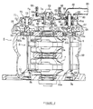
- Fig. 2 is a cross-sectional view of the engine device;
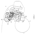
- Fig. 3 is a side view of the engine device;
- Fig. 4 is a side view illustrated with the engine cover being removed;
- Fig. 5 is a cross-sectional view of a water pump part according to another embodiment.
- an engine room 3 is disposed in front of the front wheels 2
- an engine 4 is equipped within the engine room 3
- a radiator 5 is located in the front side of the engine 4.
- This engine 4 is 2-cylinder, 4-stroke engine and disposes an oil pan 700 at the bottom of an engine body 6.
- a crankshaft 7 is disposed within the engine body 6 along the vehicle's width direction, and balancer shafts 8, 9 are disposed in the front and rear side of the crankshaft along the width direction.
- branch exhaust passages 11, 12 and branch intake passages 13, 14 for each cylinder.
- the branch exhaust passages 11, 12 are opened and closed by the corresponding exhaust valve 15 disposed in respectively
- the branch intake passages 13, 14 are opened and closed by the corresponding intake valve 16 disposed in respectively.
- the exhaust valve 15 and the intake valve 16 are driven by cams 19, 20 disposed on camshafts 17, 18.
- the branch exhaust passages 11, 12 are collected, and to this collected exhaust passage 21 is connected an exhaust pipe 22.
- the exhaust pipe 22 connected to each cylinder is collected, and the collected exhaust pipe 23 passes from the front-side of the engine body 6 through the underneath and extends rearward.
- a catalyst 24 is provided to the exhaust pipe 23.
- the branch intake passages 13, 14 are collected, and in this collected intake passage 25 is provided a throttle body 26 to the cylinder head 10.
- the throttle body 26 has an intake passage 28 connecting to the intake passage 25 of each cylinder, and furthermore, an intake manifold 30 is connected to the throttle body 26.
- an injector 35 is disposed on the cylinder head 10.
- a throttle valve 40 controlling the flow rate of the respective intake passage 28. This throttle valve 40 is controlled in accordance with information of the engine speed and the throttle openings.
- the crankshaft 7 is rotatably supported on bearings 50a.
- a balancer shaft 8 is arranged that one end portion 8a is rotatably supported through a needle bearing 51 and another end portion 8b is rotatably supported through a ball bearing 52.
- a balancer shaft 9 is also arranged in the same manner that one end portion 9a is rotatably supported through a needle bearing 53 and another end portion 9b is rotatably supported through a ball bearing 54.
- Each of the balancers 8, 9 is inserted from the end portion 8a, 9a of the opening 50b, 50c of the cylinder block 50 and assembled the ball bearing 52, 54 to the opening 50b, 50c.
- a gear 55 is mounted on the crankshaft 7, while gears 56 and 57 are mounted on the balancer shaft 8 and 9, respectively.
- the gears 56 and 57 respectively engage the gear 55.
- the balancer shafts 8 and 9 are interlocked to rotate together through gears 55, 56 and 57.
- One side of the cylinder block 50 is covered with the engine cover 58, 50 that the engine cover 58 forms a cam chain chamber 59.
- a cam gear 60 is disposed on the crankshaft 7, and a cam chain 61 is fitted over between the cam gear 60 and a gear disposed on the camshafts 17, 18 (not shown).
- the camshafts 17, 18 are interlocked to rotate by rotating of the crankshaft 7 through the cam chain 61, and the exhaust valve 15 and the intake valve 16 are opened and closed with the predetermined timing.
- An end portion 7a of the crankshaft 7 is protruded from an opening 58a of the engine cover 58, and a driving pulley 62 is mounted on the protruding end portion 7a with a locking bolt 63. Between a shaft 62a of the driving pulley 62 and the opening 58a is sealed with sealing member 64.
- a driving belt 66 is fitted over between the driving pulley 62 and a air compressor 65 disposed on the front side of the engine, and a driving belt 68 is fitted over between the driving pulley 62 and an alternator 67 disposed on the rear side of the engine.
- An oil pump 70 and a water pump 80 are integrally incorporated in the engine cover 58. That is to say, the oil pump 70 is integrally formed so that the pump housing 71 is one part of the engine cover 58, and to assemble the pump housing 71 with a cover housing 72 forms a pump chamber 73.
- a pump shaft 75 with blades 74 is rotatably supported between the pump housing 71 and the cover housing 72.
- An engaging protrusion 75a is formed on a tip of the pump shaft 75.
- An engaging recess 8c is formed on a tip of the balancer shaft 8 positioned opposite to the pump shaft 75.
- the engaging protrusion 75a of the pump shaft 75 is engaged with the engaging recess 8c of the balancer shaft 8, and the balancer shaft 8 and the pump shaft 75 are coupled integrally and rotatably. Oil is supplied to each part of the engine 4 by rotating of the pump shaft 75.
- the water pump 80 is also formed integrally so that the pump housing 81 is one part of the engine cover 58, and to assemble the pump housing 81 with a cover housing 82 forms a pump chamber 83.
- a pump shaft 85 with blades 84 is rotatably supported through the ball bearing 86.
- An engaging protrusion 85a is formed on a tip of the pump shaft 85.
- An engaging recess 9c is formed on a tip of the balancer shaft 9 positioned opposite to the pump shaft 85.
- the engaging protrusion 85a of the pump shaft 85 is engaged with the engaging recess 9c of the balancer shaft 9, and the balancer shaft 9 and the pump shaft 85 are coupled integrally and rotatably.
- the pump housing 81 is protruded into the cam chain chamber 59, and it is configured to be in a small size by that the pump shaft 85 is sealed in this pump housing 81 with a mechanical sealing member 98 and an oil-sealing member 99.
- the mechanical sealing member 98 and the oil-sealing member 99 shut out the cooling water and oil, and a weep hole 81 a is formed between the mechanical sealing member 98 and the oil-sealing member 99.
- a cooling water intake passage 90 is provided, and the cooling water from the radiator 5 is supplied to the pump chamber 83 through the cooling water intake passage 90.
- the cooling water is supplied from a cooling water discharging passage 91 formed in the cover housing 82 and the engine cover 58 to each part of the engine.
- a cooling water passage 101 is formed in the cover housing 100 and is communicated with a thermostat 88 disposed in the engine cover 58. Cooling water supplied from the radiator 5 is passed through the thermostat 88 via connection pipe 89 and thereafter supplied to the pump chamber 83 through the cooling water passage 101.
- the thermostat housing 88a as part of the engine cover is formed together with the engine cover, resulting in the reduction of the number of components and the prevention of occurrence of vibration and water leakage which may be produced in case of the thermostat housing and the engine cover being separately formed.
- the balancer shafts 8, 9 are rotatably supported on the engine body 6, the auxiliary such as the oil pump 70, water pump 80 or the like is rotatably supported on the engine cover 58, the engine auxiliary and the balancer shafts 8, 9 are coupled to rotate together, and the central-shaft-directly-driven-system is employed, it is allowed to reduce the load applied on the bearings and to reduce in volume of the bearings.
- the balancer shafts 8, 9 are rotatably supported on the engine body 6, the auxiliary such as the oil pump 70 and water pump 80 is rotatably supported on the engine cover 58, the engine auxiliary and the balancer shafts 8, 9 are coupled to rotate together, and the central-shaft-directly-driven-system is employed, it is allowed to reduce the load applied on the bearings and to reduce in volume of the bearings. Further, the positioning of the crankshaft relative to the auxiliary shafts is easily and accurately carried out as the end of the crankshaft is projected out of the engine cover and then sealed.
- auxiliaries such as an oil pump 70 and water pump 80 into the engine cover 58 allows the reduction in the number of auxiliary components to be assembled, as well as the number of locations to be sealed. It is also allowed to reduce the number of components of the oil pump 70 and water pump 80 to be incorporated, to reduce the load applied on the bearings and to reduce in volume of the bearings due to the employment of the central-shaft-directly-driven-system.
- integral incorporation of the auxiliary into the engine cover allows the reduction in the number of auxiliary components to be assembled, as well as the number of locations to be sealed.
- the balancer shafts are rotatably supported on the engine body, the auxiliary is rotatably supported on the engine cover, the engine auxiliary and the balancer shafts are coupled to rotate together, and the central-shaft-directly-driven-system is employed, it is allowed to reduce the load applied on the bearings and to reduce in volume of the bearings. Further, the positioning of the crankshaft relative to the auxiliary shafts is easily and accurately carried out as the end of the crankshaft is projected out of the engine cover and then sealed.
Landscapes
- Engineering & Computer Science (AREA)
- Mechanical Engineering (AREA)
- General Engineering & Computer Science (AREA)
- Chemical & Material Sciences (AREA)
- Combustion & Propulsion (AREA)
- Physics & Mathematics (AREA)
- Acoustics & Sound (AREA)
- Lubrication Of Internal Combustion Engines (AREA)
- Cylinder Crankcases Of Internal Combustion Engines (AREA)
Abstract
Description
Claims (10)
- An engine device (1) having an engine body (6) provided with a crankshaft (7) and balancer shafts (8,9) adapted to rotate in association with the crankshaft (7), with the engine body (6) covered with an engine cover (58), characterized in that engine auxiliary (70,80) is integrally incorporated in the engine cover (58).
- An engine device (1) according to claim 1, characterized in that the engine auxiliary (70,80) is coupled to the balancer shafts (8,9) so that both the engine auxiliary (70,80) and the balancer shafts (8,9) are allowed to rotate together.
- An engine device (1) according to claim 1 or 2, characterized in that the balancer shafts (8,9) are rotatably supported on the engine body (6), the end of the crankshaft (7) is sealed after the insertion into the engine cover (6), with the engine auxiliary (70,80) rotatably supported, and the engine auxiliary (70,80) and the balancer shafts (8,9) are coupled to rotate together.
- An engine device (1) according to at least one of the preceding claims 1 to 3, characterized in that the engine auxiliary is an oil pump (70) and/or a water pump (80).
- An engine device (1) according to claim 4, characterized in that the oil pump (70) is integrally formed so that a pump housing (71) is one part of the engine cover (58), said pump housing (71) forms together with a cover housing (72) a pump chamber (73).
- An engine device (1) according to claim 5, characterized in that an engaging protrusion (75a) of a pump shaft (75) is in engagement with an engaging recess (8c) formed on a tip of said balancer shaft (8) and the balancer shaft (8) and the pump shaft (75) are coupled integrally rotatably.
- An engine device (1) according to at least one of the preceding claims 4 to 6, characterized in that the water pump (80) is formed integrally so that a pump housing (81) is one part of the engine cover (58), said pump housing (81) forms together with a cover housing (82) a pump chamber (83).
- An engine device (1) according to claim 7, characterized in that an engaging protrusion (85a) of a pump shaft (85) is in engagement with an engaging recess (9c) of the balancer shaft (9) and the balancer shaft (9) and the pump shaft (85) are coupled integrally rotatably.
- An engine device (1) according to at least one of the preceding claims 1 to 8, characterized in that in a cylinder block (50) forming the engine body (6) the crankshaft (7) is supported on bearings (50a) and that a first (8) of the balancer shafts (8,9) is at one end portion (8a) rotatably supported by a needle bearing (51), whereas the other end portion (8b) is supported by a ball bearing (52).
- An engine device (1) according to at least one of the preceding claims 1 to 9, characterized in that a cylinder block (50) forming the engine body (6), a second (9) of the balancer shafts (8, 9) is at one end portion (9a) rotatably supported by a needle bearing (53), whereas the other end portion (9b) is rotatably supported by a ball bearing (54).
Applications Claiming Priority (2)
| Application Number | Priority Date | Filing Date | Title |
|---|---|---|---|
| JP14376099 | 1999-05-24 | ||
| JP11143760A JP2000337116A (en) | 1999-05-24 | 1999-05-24 | Engine equipment |
Publications (3)
| Publication Number | Publication Date |
|---|---|
| EP1065357A2 true EP1065357A2 (en) | 2001-01-03 |
| EP1065357A3 EP1065357A3 (en) | 2001-03-28 |
| EP1065357B1 EP1065357B1 (en) | 2004-09-08 |
Family
ID=15346394
Family Applications (1)
| Application Number | Title | Priority Date | Filing Date |
|---|---|---|---|
| EP20000111189 Expired - Lifetime EP1065357B1 (en) | 1999-05-24 | 2000-05-24 | Engine device |
Country Status (3)
| Country | Link |
|---|---|
| EP (1) | EP1065357B1 (en) |
| JP (1) | JP2000337116A (en) |
| DE (1) | DE60013504T2 (en) |
Cited By (1)
| Publication number | Priority date | Publication date | Assignee | Title |
|---|---|---|---|---|
| AT511074A4 (en) * | 2011-06-22 | 2012-09-15 | Avl List Gmbh | INTERNAL COMBUSTION ENGINE WITH AT LEAST ONE PENDING PISTON |
Families Citing this family (6)
| Publication number | Priority date | Publication date | Assignee | Title |
|---|---|---|---|---|
| JP3860983B2 (en) * | 2001-09-25 | 2006-12-20 | 株式会社クボタ | Water cooling engine |
| DE102005026786A1 (en) * | 2005-06-10 | 2006-12-21 | Audi Ag | Automotive seal located between mass balance compensation module and pump shaft has a dynamic seal and a static seal mounted on a common base |
| JP5489598B2 (en) * | 2009-08-25 | 2014-05-14 | ダイハツ工業株式会社 | Balance device in internal combustion engine |
| CN102518512B (en) * | 2011-12-19 | 2013-12-18 | 奇瑞汽车股份有限公司 | Transmission structure of oil pump |
| JP7238691B2 (en) * | 2019-08-23 | 2023-03-14 | マツダ株式会社 | Engine lubrication and cooling system |
| CN114294070B (en) * | 2021-12-23 | 2022-09-23 | 中国北方发动机研究所(天津) | Drive structure with adjustable oil pump and water pump axiality |
Family Cites Families (4)
| Publication number | Priority date | Publication date | Assignee | Title |
|---|---|---|---|---|
| US1120803A (en) * | 1912-10-17 | 1914-12-15 | Claud H Foster | Engine. |
| US3452610A (en) * | 1968-01-17 | 1969-07-01 | Us Army | Interchangeable dual gear train assemblies |
| US4321896A (en) * | 1979-12-18 | 1982-03-30 | Cummins Engine Company | Gear plate assembly for mounting and positioning an accessory drive train |
| DE4128432C2 (en) * | 1991-08-27 | 2000-04-27 | Deutz Ag | Wheel drive |
-
1999
- 1999-05-24 JP JP11143760A patent/JP2000337116A/en active Pending
-
2000
- 2000-05-24 DE DE2000613504 patent/DE60013504T2/en not_active Expired - Lifetime
- 2000-05-24 EP EP20000111189 patent/EP1065357B1/en not_active Expired - Lifetime
Cited By (3)
| Publication number | Priority date | Publication date | Assignee | Title |
|---|---|---|---|---|
| AT511074A4 (en) * | 2011-06-22 | 2012-09-15 | Avl List Gmbh | INTERNAL COMBUSTION ENGINE WITH AT LEAST ONE PENDING PISTON |
| AT511074B1 (en) * | 2011-06-22 | 2012-09-15 | Avl List Gmbh | INTERNAL COMBUSTION ENGINE WITH AT LEAST ONE PENDING PISTON |
| WO2012175290A1 (en) | 2011-06-22 | 2012-12-27 | Avl List Gmbh | Internal combustion engine having at least one piston which moves to and fro |
Also Published As
| Publication number | Publication date |
|---|---|
| DE60013504T2 (en) | 2005-01-20 |
| JP2000337116A (en) | 2000-12-05 |
| EP1065357A3 (en) | 2001-03-28 |
| EP1065357B1 (en) | 2004-09-08 |
| DE60013504D1 (en) | 2004-10-14 |
Similar Documents
| Publication | Publication Date | Title |
|---|---|---|
| US6182624B1 (en) | Hydraulic control valve mounting structure in an engine | |
| US5860402A (en) | Oil pump drive for engine | |
| US5873336A (en) | Cam drive system for engine | |
| US5678516A (en) | Accessory drive arrangement for engine | |
| EP1065357B1 (en) | Engine device | |
| EP1065359B1 (en) | Engine device | |
| JP4446105B2 (en) | 4-cycle engine | |
| JP4505984B2 (en) | Lubrication structure for valve gear of internal combustion engine | |
| US7971563B2 (en) | Engine valve operating system | |
| CN117145646A (en) | engine unit | |
| EP1055803A1 (en) | Engine device | |
| JPH08200088A (en) | Chain case structure of internal combustion engine | |
| JPH10184331A (en) | Return oil scattering prevention structure for 4-cycle engine | |
| US6179582B1 (en) | Oil pump attachment structure for engine | |
| US7878165B2 (en) | Engine valve operating system | |
| US8430076B2 (en) | Engine | |
| JPH06108919A (en) | Engine oil pan structure | |
| JP4066512B2 (en) | Engine oil pump structure | |
| JPH09210136A (en) | Balancer shaft support structure in engine | |
| JP2000337117A (en) | Oil pump device | |
| JP2000337118A (en) | Oil pump mounting device for internal combustion engine | |
| CA2606776C (en) | Engine | |
| JP3614914B2 (en) | Engine crank rotation angle detector | |
| JP4161774B2 (en) | Camshaft support structure in a 4-cycle engine | |
| JP2829526B2 (en) | Engine unit for vehicle |
Legal Events
| Date | Code | Title | Description |
|---|---|---|---|
| PUAI | Public reference made under article 153(3) epc to a published international application that has entered the european phase |
Free format text: ORIGINAL CODE: 0009012 |
|
| AK | Designated contracting states |
Kind code of ref document: A2 Designated state(s): AT BE CH CY DE DK ES FI FR GB GR IE IT LI LU MC NL PT SE |
|
| AX | Request for extension of the european patent |
Free format text: AL;LT;LV;MK;RO;SI |
|
| PUAL | Search report despatched |
Free format text: ORIGINAL CODE: 0009013 |
|
| RIC1 | Information provided on ipc code assigned before grant |
Free format text: 7F 02B 67/04 A, 7F 02B 39/04 B |
|
| AK | Designated contracting states |
Kind code of ref document: A3 Designated state(s): AT BE CH CY DE DK ES FI FR GB GR IE IT LI LU MC NL PT SE |
|
| AX | Request for extension of the european patent |
Free format text: AL;LT;LV;MK;RO;SI |
|
| 17P | Request for examination filed |
Effective date: 20010507 |
|
| AKX | Designation fees paid |
Free format text: DE FR GB IT |
|
| 17Q | First examination report despatched |
Effective date: 20030228 |
|
| GRAP | Despatch of communication of intention to grant a patent |
Free format text: ORIGINAL CODE: EPIDOSNIGR1 |
|
| GRAS | Grant fee paid |
Free format text: ORIGINAL CODE: EPIDOSNIGR3 |
|
| GRAA | (expected) grant |
Free format text: ORIGINAL CODE: 0009210 |
|
| AK | Designated contracting states |
Kind code of ref document: B1 Designated state(s): DE FR GB IT |
|
| PG25 | Lapsed in a contracting state [announced via postgrant information from national office to epo] |
Ref country code: FR Free format text: LAPSE BECAUSE OF NON-PAYMENT OF DUE FEES Effective date: 20040908 |
|
| REG | Reference to a national code |
Ref country code: GB Ref legal event code: FG4D |
|
| REF | Corresponds to: |
Ref document number: 60013504 Country of ref document: DE Date of ref document: 20041014 Kind code of ref document: P |
|
| PLBE | No opposition filed within time limit |
Free format text: ORIGINAL CODE: 0009261 |
|
| STAA | Information on the status of an ep patent application or granted ep patent |
Free format text: STATUS: NO OPPOSITION FILED WITHIN TIME LIMIT |
|
| 26N | No opposition filed |
Effective date: 20050609 |
|
| EN | Fr: translation not filed | ||
| PGFP | Annual fee paid to national office [announced via postgrant information from national office to epo] |
Ref country code: DE Payment date: 20180522 Year of fee payment: 19 |
|
| PGFP | Annual fee paid to national office [announced via postgrant information from national office to epo] |
Ref country code: IT Payment date: 20180530 Year of fee payment: 19 |
|
| PGFP | Annual fee paid to national office [announced via postgrant information from national office to epo] |
Ref country code: GB Payment date: 20180518 Year of fee payment: 19 |
|
| REG | Reference to a national code |
Ref country code: DE Ref legal event code: R119 Ref document number: 60013504 Country of ref document: DE |
|
| GBPC | Gb: european patent ceased through non-payment of renewal fee |
Effective date: 20190524 |
|
| PG25 | Lapsed in a contracting state [announced via postgrant information from national office to epo] |
Ref country code: GB Free format text: LAPSE BECAUSE OF NON-PAYMENT OF DUE FEES Effective date: 20190524 Ref country code: DE Free format text: LAPSE BECAUSE OF NON-PAYMENT OF DUE FEES Effective date: 20191203 Ref country code: IT Free format text: LAPSE BECAUSE OF NON-PAYMENT OF DUE FEES Effective date: 20190524 |