EP1061690A2 - Verfahren zum Ubertragen auf mehreren Trägersignalen - Google Patents
Verfahren zum Ubertragen auf mehreren Trägersignalen Download PDFInfo
- Publication number
- EP1061690A2 EP1061690A2 EP00440135A EP00440135A EP1061690A2 EP 1061690 A2 EP1061690 A2 EP 1061690A2 EP 00440135 A EP00440135 A EP 00440135A EP 00440135 A EP00440135 A EP 00440135A EP 1061690 A2 EP1061690 A2 EP 1061690A2
- Authority
- EP
- European Patent Office
- Prior art keywords
- demodulation
- receiving device
- signals
- digital
- analog
- Prior art date
- Legal status (The legal status is an assumption and is not a legal conclusion. Google has not performed a legal analysis and makes no representation as to the accuracy of the status listed.)
- Withdrawn
Links
Images

Classifications
-
- H—ELECTRICITY
- H04—ELECTRIC COMMUNICATION TECHNIQUE
- H04L—TRANSMISSION OF DIGITAL INFORMATION, e.g. TELEGRAPHIC COMMUNICATION
- H04L5/00—Arrangements affording multiple use of the transmission path
- H04L5/02—Channels characterised by the type of signal
- H04L5/023—Multiplexing of multicarrier modulation signals, e.g. multi-user orthogonal frequency division multiple access [OFDMA]
Definitions
- the invention relates to a method for transmitting analog Information signals and a receiving device Transmission network.
- Point-to-point In transmission networks, information changes from one transmitter to another Receiver (point-to-point), from one transmitter to several receivers (Point-to-multipoint) or from several transmitters to one Transfer the receiver (multipoint-to-point).
- Point-to-multipoint Network An example of a point-to-multipoint Network is a cable television distribution network. From a broadcasting station Broadcast analog television signals become a multitude transmitted from terminal stations. Distribution networks, and in particular Cable television networks are often implemented by implementing a Return channel expanded to interactive communication networks. The Return channel is an example of a multipoint-to-point network, since all Terminals the center of the communication network via this return channel can be reached via a common access.
- EP 0 840 470 A2 describes an optical network termination unit of a hybrid Fiber optic coaxial cable access network, which is a forward channel and has a return channel described.
- the network termination unit which as Interface between the optical and the electrical subnet serves the analog signals sent by the terminal stations are digitized.
- the received digital signals either digitally using a digital one Signal processor or after conversion into analog signals analog processed further.
- the type of modulation of the analog signals is kept open.
- QAM or QPSK modulated analog signals are one or more Transmitters using at least two carriers transmitted to a receiving device.
- the modulated signals are already on the transmission network digitized.
- Demodulation to three can be carried out in the receiving device different ways are done.
- the received signals of a predetermined group of Transmission devices of a predetermined number of Demodulation units supplied the number of the number of carriers corresponds.
- Each demodulation unit selects a carrier and digitally demodulates the modulated signals of the selected one Carrier.
- those of several predetermined ones Groups of transmitters receive signals of a matrix fed. The matrix does the job, the signals the individual Supply demodulation units for digital demodulation.
- a third variant like the second variant, becomes a matrix and used several demodulation units, with the difference that the Demodulation after a digital / analog conversion using analog analog demodulators is performed.
- the invention is from the Form and topology of the transmission network independent. So it can Invention e.g. also to a point-to-point, a point-to-multipoint or a multipoint-to-point network can be applied. That is advantageous Application to the return channel of an interactive communication network, because, for example, cable telephony signals are kept below minimum Interferences can be transmitted. Also, the making is one Demodulation device in a control center of the communication network can be integrated on a single chip using a system-on-chip solution and thus particularly inexpensive and particularly good against external ones Interference protected.
- the Communication network includes a central 1, which is used for implementation a forward channel over a point-to-multipoint network of optical Fiber optic lines and optical splitters with three optical Network termination units 9, 10, 11 is connected.
- the optical Network termination units 9, 10, 11 are in turn to implement a Return channel each via an optical fiber line with the control center 1 connected.
- a Multipoint-to-point network from the network termination units 9, 10, 11 to Central 1 can be used.
- This multi-point-to-point network can also the point-to-multipoint network for implementing the forward channel his. Then e.g. for the forward and the back channel different wavelengths used.
- optical network termination units 9, 10, 11 are each further connected to end points via one or more coaxial cable networks, from of which three 12, 13, 14 are shown as examples. Include real networks for example ten network termination units and ten thousand end stations.
- the center 1 has a processing device 2, which, for example, as Digital signal processor or microprocessor plus memory, register, etc. is trained.
- the processing device 2 has one or more Interfaces to facilities outside the interactive network, e.g. one TV station for access to television signals, an Internet service provider to access the Internet, a switching center for access to a telephone network, etc.
- the center 1 transmits distribution signals, e.g. Television signals and subscriber-specific signals, e.g. Telephone signals or Internet signals via the optical network termination units to the end stations.
- the signals to be transmitted are processed in a modulation device 3 modulated, e.g. using QAM, then in an electrical / optical Converter converted into optical signals and to the optical Network termination units 9, 10, 11 transmitted.
- optical Network termination units are optically / electrically implemented and possibly a gain and equalization, etc. before forwarding to the Terminals 12, 13, 14 instead.
- the received signals before or after demodulation to the corresponding terminals, e.g. TV, telephone, computer forwarded.
- the terminals 12, 13, 14 in turn transmit QAM or QPSK modulated information signals over the respective coaxial cable network to the respective optical network termination unit 9, 10, 11, which before Forwarding to headquarters 1 an electrical / optical implementation and if necessary, perform a reinforcement, equalization, collision detection, etc.
- the Information signals include, for example, polling signals for service on demand or Internet applications and / or telephone signals.
- the center 1 are those of the three optical network termination units 9, 10, 11 received signals in three optical / electrical converters 6, 7, 8 converted into electrical signals and then one Demodulation device 4 supplied.
- the demodulation device the received signals are demodulated.
- the demodulated Signals are used for further processing of the processing device 2 fed.
- the following is a method for transmitting analog Information signals described.
- the procedure is thereby characterized in that the analog information signals to be transmitted first in at least one transmitter, e.g. the sending device a terminal of a terminal 12, 13, 14 or the control center 1, QAM or QPSK are modulated, with at least two carriers for the Transmission can be used.
- the modulated signals are over a Transmission network, e.g. the interactive communication network, at least a transceiver, e.g. an optical Network termination unit 9, 10, 11 transmitted, in which they by means of a Analog / digital converter can be digitized.
- the digitized signals then become one over the transmission network Transmit receiving device, e.g. the receiving device of the Central 1 or a terminal of a terminal 12, 13, 14.
- each demodulation unit is suitable for a carrier a digital QAM or QPSK demodulation from the received signal perform.
- the digitization of the modulated signals can instead of in the transmitting / receiving device also in the receiving device in front of the Demodulation done.
- FIG. 2 shows an embodiment of the invention Demodulation device 4 from FIG. 1.
- the demodulation device 4 includes nine demodulation units 15, 16, 17, 18, 19, 20, 21, 22, 23 and three analog / digital converters 24, 25, 26.
- each optical Network termination unit 9, 10, 11 three carriers for the transmission of modulated signals used.
- Each demodulation unit 15, 16, 17, 18, 19, 20, 21, 22, 23 is suitably modulated signals of a carrier digitally to demodulate.
- Groups of three are used for demodulation Demodulation units 15, 16, 17; 18, 19, 20; 21, 22, 23 formed the in each case the demodulation of all via an optical network termination unit 9, 10, 11 perform transmitted modulated signals; each Demodulation unit 15, 16, 17; 18, 19, 20; 21, 22, 23 of a group for a carrier.
- Each group is preceded by an analog / digital converter 24, 25, 26 Implementation of the QAM or QPSK modulated signals. If the Digitization has already taken place on the network, e.g. in a optical network termination unit 9, 10, 11 or even in the terminals 12, 13, 14 themselves, the analog / digital converters 24, 25, 26 are not required. Are the modulated signals already in a terminal or in Transfer point of the terminal 12, 13, 14 digitized, so is possibly a Multiplexer in the corresponding optical network termination unit 9, 10, 11 necessary.
- a receiving device of a transmission network for Transmission of QAM or QPSK modulated signals based on at least two different carriers are used thus at least two demodulation units 15-23 are provided are each suitable for a carrier from the received signal perform digital QAM or QPSK demodulation.
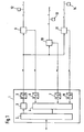
- Fig. 3 shows an embodiment of the Demodulation unit 15 from FIG. 2.
- the demodulation unit 15 includes a digital bandpass filter 32 for Filtering out a carrier, a downstream of the bandpass filter 32 Sampling rate converter 31 and two the sampling rate converter 31 in parallel downstream paths, each path having a multiplier 29, 30 and one Low pass filter 27, 28 includes. Multiplication takes place in one path with -sin ⁇ t, in the other path a multiplication with cos ⁇ t.
- the bandpass filter 32 is a digital filter, for example with 16 bits is working.
- the sampling rate converter 31, which is also used as a downsampler or Decimation filter performs a frequency conversion.
- the received signals with the frequency f1 are converted into signals with the Frequency f2 implemented, where f1> f2.
- There is a frequency conversion in a frequency range instead of that for subsequent multiplication is more appropriate.
- Each low-pass filter 27, 28 is matched, for example Filter executed. At the output of the low-pass filter 27 is the Phase component of the QAM or QPSK signal available, on Output of the low-pass filter 28, the quadrature component.
- All demodulation units 15 to 23 are constructed in the same way as the Difference that in each group three demodulation units with three different passages of their bandpass filters are to process the three different carriers.
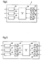
- Fig. 4 shows an embodiment of the Demodulation device 4 from FIG. 1.
- the demodulation device 4 includes three demodulation units 33, 34, 35, a matrix 36 and three Analog / digital converter 37, 38, 39.
- the signals received in the demodulation device 4 are the Demodulation units 33-35 are not supplied simultaneously, but first pass through a matrix 36 in which they are divided according to the carriers become. The split carriers then become the individual Demodulation units 33-35 for direct digital demodulation fed.
- the matrix 36 is used for division by carriers, contains three inputs, which are each connected to an analog / digital converter 37, 38, 39, and three outputs, each with a single digital QAM or QPSK demodulation unit 33-35 for subsequent digital Demodulation are connected.
- the division by carriers and the Assignment to the individual demodulation units is dependent from the access procedure e.g. after specified time slots at the TDMA or according to predetermined frequency ranges at the FDMA.
- the matrix is for example designed as a so-called Cross Connect. With a cross Connect, every input can be switched to every output.
- the structure of the demodulation units 33-35 corresponds, for example the structure of the demodulation units 15-23 from FIGS. 2 and 3 with the The difference is that no bandpass filter is required because the selection of the Carrier already occurs in the matrix. Compared to the first Only three instead of nine demodulation units are exemplary needed.
- Fig. 5 shows an embodiment of the Demodulation device 4 from FIG. 1.
- the demodulation device 4 includes three demodulators 40, 41, 42, three digital / analog converters 43, 44, 45, a matrix 46 and three analog / digital converters 47, 48, 49.
- Matrix 46 and the analog / digital converter 47, 48, 49 corresponds to the matrix 36 and the analog / digital converters 37, 38, 39 from Fig. 4.
- digital Demodulation units 33-35 instead of digital Demodulation units 33-35 from FIG. 4 three conventional analog QAM or QPSK demodulators 40, 41, 42 with upstream digital / analog Converters 43, 44, 45 used.
- the transmitting / receiving device e.g. an optical network termination unit
- Digitization is a multiplexing of signals from several Transmission facilities are carried out.
- the multiplexed signals become the receiving device, e.g. Headquarters, transferred.
- the Receiving device of the first embodiment is before Demodulation performed a demultiplexing and the demultiplexed signals are each a group of Demodulation units supplied.
- the matrix of the receiving device the second and third exemplary embodiments are divided according to Carriers and demultiplexing in one step. The matrix becomes this programmed accordingly.
- Modulation types are used, e.g. PSK, etc. But then in the network nevertheless provided at least two carriers; so-called subcarrier multiplex. It is irrelevant whether individual transmitters only Send out modulated signals on a carrier and the entire network but through different transmitters with different carriers includes a total of at least two carriers or transmitters are provided, the modulated signals on different carriers send out.
- the individual carriers can for example for the Provision of different services may be reserved, e.g. Cable telephony, Internet, service on demand, etc.
Landscapes
- Engineering & Computer Science (AREA)
- Signal Processing (AREA)
- Computer Networks & Wireless Communication (AREA)
- Optical Communication System (AREA)
- Digital Transmission Methods That Use Modulated Carrier Waves (AREA)
Abstract
Description
- Fig. 1
- eine schematische Darstellung eines interaktiven Kommunikationsnetzes,
- Fig. 2
- einen schematisch dargestellten Aufbau einer erfindungsgemäßen Demodulationseinrichtung aus Fig.1,
- Fig. 3
- eine erfindungsgemäße Ausgestaltung einer Demodulationseinheit der Demodulationseinrichtung aus Fig. 2,
- Fig. 4
- einen schematisch dargestellten Aufbau einer weiteren erfindungsgemäßen Demodulationseinrichtung aus Fig. 1 und
- Fig. 5
- einen schematisch dargestellten Aufbau einer weiteren erfindungsgemäßen Demodulationseinrichtung aus Fig. 1.
Claims (12)
- Verfahren zum Übertragen von analogen Informationssignalen,
dadurch gekennzeichnet, daß die analogen Informationssignale in mindestens einer Sendeeinrichtung QAM oder QPSK moduliert werden, wobei mindestens zwei Träger für die Übertragung verwendet werden, daß die modulierten Signale über ein Übertragungsnetz zu einer Sende-/Empfangseinrichtung übertragen werden, in der sie mittels eines Analog/Digital Umsetzers digitalisiert werden, daß die digitalisierten Signale über das Übertragungsnetz zu einer Empfangseinrichtung übertragen werden, in der sie gleichzeitig mindestens zwei digitalen Demodulationseinheiten (15-23, 33-35, 40-45) zugeführt werden, wobei jede Demodulationseinheit (15-23, 33-35, 40-45) geeignet ist, für einen Träger aus dem empfangenen Signal eine digitale QAM bzw. QPSK Demodulation durchzuführen. - Verfahren nach Anspruch 1, dadurch gekennzeichnet, daß die Digitalisierung der modulierten Signale anstelle in der Sende/Empfangseinrichtung in der Empfangseinrichtung vor der Demodulation erfolgt.
- Verfahren nach Anspruch 1 oder 2 , dadurch gekennzeichnet, daß die in der Empfangseinrichtung empfangenen Signale den Demodulationseinheiten (15-23, 33-35, 40-45) nicht gleichzeitig zugeführt werden, sondern zunächst eine Matrix (36, 46) durchlaufen, in der sie nach den Trägern aufgeteilt werden und die aufgeteilten Träger dann anschließend einzelnen Demodulationseinheiten (33-35, 40-45) zur direkten digitalen Demodulation zugeführt werden.
- Verfahren nach Anspruch 3, dadurch gekennzeichnet, daß die digitale Demodulation durch Digital/Analog Umsetzung (43-45) und anschließender analoger Demodulation mittels analogen QAM bzw. QPSK Demodulatoren (40-42) erfolgt.
- Verfahren nach Anspruch 1, dadurch gekennzeichnet, daß die modulierten Signale über den Rückkanal eines interaktiven Kommunikationsnetzes übertragen werden.
- Verfahren nach Anspruch 5, dadurch gekennzeichnet, daß als Sendeeinrichtung die Sendeeinrichtung einer Endstelle (12-14), als Sende/Empfangseinrichtung die Sende-/Empfangseinrichtung einer optische Netzabschlußeinrichtung (9-11) und als Empfangseinrichtung die Empfangseinrichtung einer Zentrale (1) des Kommunikationsnetzes verwendet wird.
- Verfahren nach Anspruch 1, dadurch gekennzeichnet, daß in der Sende/Empfangseinrichtung nach der Digitalisierung eine Multiplexbildung von Signalen mehrerer Sendeeinrichtungen durchgeführt wird, daß die gemultiplexten Signale zur Empfangseinrichtung übertragen werden, und daß in der Empfangseinrichtung vor der Demodulation eine Demultiplexbildung durchgeführt und die demultiplexten Signale jeweils einer Gruppe von Demodulationseinheiten zugeführt werden.
- Verfahren nach Anspruch 3, dadurch gekennzeichnet, daß in der Sende/Empfangseinrichtung nach der Digitalisierung eine Multiplexbildung von Signalen mehrerer Sendeeinrichtungen durchgeführt wird, daß die gemultiplexten Signale zur Empfangseinrichtung übertragen werden, und daß in der Matrix der Empfangseinrichtung die Aufteilung nach Trägern und die Demultiplexbildung in einem Schritt erfolgen.
- Empfangseinrichtung eines Übertragungsnetzes, dadurch gekennzeichnet, daß das Übertragungsnetz zur Übertragung von QAM oder QPSK modulierten Signalen, die auf mindestens zwei unterschiedlichen Trägern übertragen werden, dient, und daß die Empfangseinrichtung mindestens zwei Demodulationseinheiten (15-23, 33-35, 40-45) beinhaltet, die jeweils geeignet sind, für einen Träger aus dem empfangenen Signal eine digitale QAM bzw. QPSK Demodulation durchzuführen.
- Empfangseinrichtung nach Anspruch 9, dadurch gekennzeichnet, daß jede Demodulationseinheit (15-23, 33-35, 40-45) ein digitales Bandpaßfilter (32) zum Herausfiltern eines Trägers, einen dem Bandpaßfilter (32) nachgeschalteten Abtastratenwandler (31) und zwei dem Abtastratenwandler (31) parallel nachgeschaltete Pfade beinhaltet, wobei jeder Pfad einen Multiplizierer (29, 30) und ein Tiefpaßfilter (27, 28) beinhaltet, und daß in dem einen Pfad eine Multiplikation mit -sin ωt und in dem anderen Pfad eine Multiplikation mit cos ωt erfolgt.
- Empfangseinrichtung nach Anspruch 9, dadurch gekennzeichnet, daß die Empfangseinrichtung eine Matrix (36, 46) zur Aufteilung nach Trägern beinhaltet, und jeder Ausgang der Matrix (36, 46) mit einer einzelnen digitalen QAM bzw. QPSK Demodulationseinheit (33-35, 40-45) zur anschließenden digitalen Demodulation verbunden ist.
- Empfangseinrichtung nach Anspruch 9, dadurch gekennzeichnet, daß den Demodulationseinheiten (15-23, 33-35, 40-45) mindestens ein Analog/Digital Umsetzer (24-26, 37-39, 47-49) vorgeschaltet ist.
Applications Claiming Priority (2)
| Application Number | Priority Date | Filing Date | Title |
|---|---|---|---|
| DE19927090A DE19927090A1 (de) | 1999-06-15 | 1999-06-15 | Verfahren zum Übertragen von analogen Informationssignalen |
| DE19927090 | 1999-06-15 |
Publications (2)
| Publication Number | Publication Date |
|---|---|
| EP1061690A2 true EP1061690A2 (de) | 2000-12-20 |
| EP1061690A3 EP1061690A3 (de) | 2003-12-10 |
Family
ID=7911192
Family Applications (1)
| Application Number | Title | Priority Date | Filing Date |
|---|---|---|---|
| EP00440135A Withdrawn EP1061690A3 (de) | 1999-06-15 | 2000-05-09 | Verfahren zum Ubertragen auf mehreren Trägersignalen |
Country Status (3)
| Country | Link |
|---|---|
| EP (1) | EP1061690A3 (de) |
| JP (1) | JP2001028609A (de) |
| DE (1) | DE19927090A1 (de) |
Family Cites Families (3)
| Publication number | Priority date | Publication date | Assignee | Title |
|---|---|---|---|---|
| US5289464A (en) * | 1992-09-21 | 1994-02-22 | At&T Bell Laboratories | Frequency-multiplexed cellular telephone cell site base station and method of operating the same |
| JPH06224852A (ja) * | 1993-01-25 | 1994-08-12 | Matsushita Electric Ind Co Ltd | 光伝送方式 |
| DE19643872A1 (de) * | 1996-10-31 | 1998-05-07 | Alsthom Cge Alcatel | Optische Netzabschlußeinheit eines hybriden Glasfaser-Koaxialkabel-Zugangsnetzes |
-
1999
- 1999-06-15 DE DE19927090A patent/DE19927090A1/de not_active Withdrawn
-
2000
- 2000-05-09 EP EP00440135A patent/EP1061690A3/de not_active Withdrawn
- 2000-05-26 JP JP2000155800A patent/JP2001028609A/ja not_active Withdrawn
Also Published As
| Publication number | Publication date |
|---|---|
| DE19927090A1 (de) | 2000-12-28 |
| EP1061690A3 (de) | 2003-12-10 |
| JP2001028609A (ja) | 2001-01-30 |
Similar Documents
| Publication | Publication Date | Title |
|---|---|---|
| EP2499878B1 (de) | Master-einheit, remote-einheit sowie multiband-übertragungssystem | |
| EP0031457A2 (de) | Breitband-Vermittlungssystem | |
| DE3786723T2 (de) | Vermittlungstechniken für Frequenzmultiplex-Kommunikationssysteme. | |
| EP0386482B1 (de) | Optisches Nachrichtenübertragungssystem für den Teilnehmeranschlussbereich | |
| EP0974210B1 (de) | System zur übertragung hochratiger mehrwertdienste im terrestrischen digitalen rundfunk | |
| EP0200016A2 (de) | Verfahren zur Übertragung von Information über elektrische Energieversorgungsnetze | |
| DE19643872A1 (de) | Optische Netzabschlußeinheit eines hybriden Glasfaser-Koaxialkabel-Zugangsnetzes | |
| EP0386466B1 (de) | Optisches Nachrichtenübertragungssystem für den Teilnehmeranschlussbereich | |
| DE69513534T2 (de) | Hybrides faser-/koaxial kommunikationssystem für bild- und fernsprechsignalen | |
| DE3632047C2 (de) | Optisches Nachrichtenübertragungssystem für Schmalband- und Breitband-Nachrichtensignale | |
| DE69706296T2 (de) | Verfahren und vorrichtung für kabelfernsehnetzwerke | |
| EP0031014B1 (de) | Fernmeldesystem | |
| DE3403206A1 (de) | Lichtwellenleiter-verteilnetz fuer fernseh- und tonprogramme | |
| DE19719425A1 (de) | System zur optischen Übertragung von Informationen | |
| DE4436818C1 (de) | Teilnehmeranschlußnetz | |
| EP0706292A1 (de) | Schaltungsanordnung zur Steuerung der Übertragung von Informationen für interaktive Dienste | |
| DE60113960T2 (de) | Zweiwegnetzwerk zur Verteilung von Kabel-TV-Signalen an Endpunkte mittels optischer Fasern | |
| EP0612460B1 (de) | Funkübertragungsverfahren mittels einer ortsfesten basisstation und einer vielzahl voneinander unabhängiger ortsfester teilnehmerstationen | |
| EP1061690A2 (de) | Verfahren zum Ubertragen auf mehreren Trägersignalen | |
| DE19701888A1 (de) | System zur optischen Übertragung von Informationen | |
| DE3208308A1 (de) | Verfahren zum uebertragen von frequenzmodulierten hoerrundfunksignalen ueber ein digitales breitbandverteilnetz | |
| EP0031458A2 (de) | Lichtwellenleiter-Frequenzmultiplex-Übertragungssystem | |
| EP0710024A2 (de) | Hausnetz zur Anbindung von Teilnehmern an ein öffentliches Verteilnetz für Video- und/oder Audiosignale | |
| DE4405460C1 (de) | Anschlußleitungsnetz | |
| DE3325569A1 (de) | Digitales fernmeldesystem |
Legal Events
| Date | Code | Title | Description |
|---|---|---|---|
| PUAI | Public reference made under article 153(3) epc to a published international application that has entered the european phase |
Free format text: ORIGINAL CODE: 0009012 |
|
| AK | Designated contracting states |
Kind code of ref document: A2 Designated state(s): AT BE CH CY DE DK ES FI FR GB GR IE IT LI LU MC NL PT SE |
|
| AX | Request for extension of the european patent |
Free format text: AL;LT;LV;MK;RO;SI |
|
| PUAL | Search report despatched |
Free format text: ORIGINAL CODE: 0009013 |
|
| AK | Designated contracting states |
Kind code of ref document: A3 Designated state(s): AT BE CH CY DE DK ES FI FR GB GR IE IT LI LU MC NL PT SE |
|
| AX | Request for extension of the european patent |
Extension state: AL LT LV MK RO SI |
|
| RIC1 | Information provided on ipc code assigned before grant |
Ipc: 7H 04L 5/06 A |
|
| AKX | Designation fees paid |
Designated state(s): AT BE CH CY DE DK ES FI FR GB GR IE IT LI LU MC NL PT SE |
|
| STAA | Information on the status of an ep patent application or granted ep patent |
Free format text: STATUS: THE APPLICATION IS DEEMED TO BE WITHDRAWN |
|
| 18D | Application deemed to be withdrawn |
Effective date: 20040612 |