EP1059422A1 - Dispositif de protection du méchanisme de commande des volets d'une roue directrice d'entrée de turboréacteur - Google Patents
Dispositif de protection du méchanisme de commande des volets d'une roue directrice d'entrée de turboréacteur Download PDFInfo
- Publication number
- EP1059422A1 EP1059422A1 EP00401608A EP00401608A EP1059422A1 EP 1059422 A1 EP1059422 A1 EP 1059422A1 EP 00401608 A EP00401608 A EP 00401608A EP 00401608 A EP00401608 A EP 00401608A EP 1059422 A1 EP1059422 A1 EP 1059422A1
- Authority
- EP
- European Patent Office
- Prior art keywords
- control
- link
- protection device
- fusible
- transmission
- Prior art date
- Legal status (The legal status is an assumption and is not a legal conclusion. Google has not performed a legal analysis and makes no representation as to the accuracy of the status listed.)
- Granted
Links
Images



Classifications
-
- F—MECHANICAL ENGINEERING; LIGHTING; HEATING; WEAPONS; BLASTING
- F01—MACHINES OR ENGINES IN GENERAL; ENGINE PLANTS IN GENERAL; STEAM ENGINES
- F01D—NON-POSITIVE DISPLACEMENT MACHINES OR ENGINES, e.g. STEAM TURBINES
- F01D17/00—Regulating or controlling by varying flow
- F01D17/10—Final actuators
- F01D17/12—Final actuators arranged in stator parts
- F01D17/14—Final actuators arranged in stator parts varying effective cross-sectional area of nozzles or guide conduits
- F01D17/16—Final actuators arranged in stator parts varying effective cross-sectional area of nozzles or guide conduits by means of nozzle vanes
- F01D17/162—Final actuators arranged in stator parts varying effective cross-sectional area of nozzles or guide conduits by means of nozzle vanes for axial flow, i.e. the vanes turning around axes which are essentially perpendicular to the rotor centre line
-
- F—MECHANICAL ENGINEERING; LIGHTING; HEATING; WEAPONS; BLASTING
- F16—ENGINEERING ELEMENTS AND UNITS; GENERAL MEASURES FOR PRODUCING AND MAINTAINING EFFECTIVE FUNCTIONING OF MACHINES OR INSTALLATIONS; THERMAL INSULATION IN GENERAL
- F16C—SHAFTS; FLEXIBLE SHAFTS; ELEMENTS OR CRANKSHAFT MECHANISMS; ROTARY BODIES OTHER THAN GEARING ELEMENTS; BEARINGS
- F16C7/00—Connecting-rods or like links pivoted at both ends; Construction of connecting-rod heads
- F16C7/02—Constructions of connecting-rods with constant length
-
- F—MECHANICAL ENGINEERING; LIGHTING; HEATING; WEAPONS; BLASTING
- F16—ENGINEERING ELEMENTS AND UNITS; GENERAL MEASURES FOR PRODUCING AND MAINTAINING EFFECTIVE FUNCTIONING OF MACHINES OR INSTALLATIONS; THERMAL INSULATION IN GENERAL
- F16C—SHAFTS; FLEXIBLE SHAFTS; ELEMENTS OR CRANKSHAFT MECHANISMS; ROTARY BODIES OTHER THAN GEARING ELEMENTS; BEARINGS
- F16C2326/00—Articles relating to transporting
- F16C2326/43—Aeroplanes; Helicopters
Definitions
- the field of the invention is that of turbojet engines that have a steerable wheel entrance, consisting of shutters, whose orientation tilt is controlled during operation.
- the invention relates, in particular, to the protection of the orientation control cylinder of these shutters.
- the object of the invention is therefore to ensure the flight safety of airplanes using such turbojet engines by protecting sensitive parts, such as the wheel flap control cylinder entry director.
- the fuse part of transmission is unique and constitutes a link in the control mechanism placed between the control cylinder and the control ring.
- the transmission fuse part is a connecting rod having a section with a narrowed section between the control cylinder and the control ring, and that pivoting transmission part is used at the cylinder outlet, before the link and articulated on these two elements.
- This tubular protection can advantageously be made by a double thickness heat shrink tubing.
- the section with narrowed section may have, as well as the entire link, a tubular shape.
- the transmission fuse part is a fuse bolt with narrowed section, placed in a yoke downstream of the pivoting transmission part.
- Figure 1 represents, seen from the outside, the shutter control mechanism equipped with protection device according to the invention.
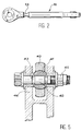
- Figure 2 shows a link from the operating mechanism, used as part fuse.
- Figure 3 shows, in section, another type of link used as a fusible part and fitted with tubular protection.
- Figure 4 shows, in section, another type of fusible link.
- Figure 5 shows, in section, a yoke downstream of a pivoting transmission part with an axis used as a fuse.
- Figure 6 shows, in section, the yoke downstream of a pivoting part, equipped with means of game adjustment.
- Figure 7 shows, in section, another means for adjusting the clearance of the downstream yoke of a piece of swivel drive.
- Figure 8 shows, in external view rider, positioning stops of the ring control, used in conjunction with the protection according to the invention.
- FIG. 9 shows, in detail rider, the anti-deflection piece used with the protection device according to the invention.
- the entry of a turbojet engine is formed by an inlet casing 1 of a input steering wheel which aims to adjust the air flow entering the turbojet engine.
- This wheel entry director has tilting shutters, not represented, but suggested by their control lever 2 placed outside the inlet housing 1. They are integral with the flaps and mounted each pivoting around a pivot axis of flaps 3 perpendicular to the fictitious axis of the turbojet engine.
- the inclination of the flaps is obtained by means of a control cylinder 8 placed at outside of the inlet housing 1 and including the piston 7 activates a control ring 4 flaps, by via a pivoting transmission part 6.
- the control ring 4 makes the entire periphery of the inlet housing 1.
- the end of each lever control of the two flaps is pivotally mounted on this control ring 4. In this way, when this ring 4 turns slightly around the inlet housing 1, each of the wheel flaps entry director pivots around its axis 3.
- a link 10 transmits the movement of the pivoting transmission part 6 to the ring of control 4.
- it is pivotally mounted in a yoke 12 of the control ring 4, around an axis pivot 5 parallel to the axis of the turbojet engine and fixed relative to the control ring 4.
- the rod 10 is also mounted pivoting in a downstream yoke 11 of the pivoting part transmission 6.
- the rod 10 is the fusible part and has a weakened part constituted by a section with a narrowed section 13 of the link.
- the reasons for the presence of this party at narrowed section 13 were exposed earlier. The result is that a shock or mechanical stress excessively large on one of the flaps, does not cause not the deterioration of the control cylinder 8. Indeed, the section with narrowed section 13 will be the first to give way in the event of a shock throughout the entire mechanism flap control.
- the protective part 21 is transparent for ability to check condition of constricted portion 23.
- the length of the link can be adjustable, thanks to two threaded ends 22 screwing into the handle 24 of the male part of a screed.
- Figure 4 shows another embodiment of the link, referenced 30. It is constituted by a tubular part 32 which has a section part narrowed 33. It can be seen that the interior of the rod 30 is completed by a rod 34 secured to the sleeve 36 of a first male part of a yoke and coming to lodge inside the handle 35 of another male part of another yoke. These two are expected sleeves 35 and 36 are threaded, and that the piece tubular 32 is tapped so that it can be adjusted the length of the rod by screwing and unscrewing.
- this is placed in a fuse bolt 42 of a clevis of the shutter control mechanism. Indeed, it it is possible to place this fuse part on the axis pivot 5 of Figure 1 in a yoke between the rod 10 and the control ring 4. In this case, the rod does not have a section with a narrowed section.
- Figure 6 shows another embodiment allowing to adjust the play around the ball joint 41 of the rod 40.
- the part or parts weakened 53 are placed on a clevis pin 52 does not part of a bolt.
- the part female of clevis 56 extends so that that an adjustment bolt 57 can pass through this yoke 56 and that an adjustment nut 55 makes it possible to adjust the clearance around ball 41.
- Figure 7 shows yet another adjustment of the clearance of the ball joint 41 of the connecting rod 40.
- Another adjustment bolt 67 is used placed inside the female part of the yoke 68 and an adjustment nut 65.
- Figure 1 also shows a coin anti-deflection 14 placed around the joint consisting of the first end of the link 10 and downstream yoke 11 of the pivoting part of transmission 6. Indeed, in the case where the party fuse 13 of the link 10 blows, the latter found split into two parts. It turns out to be necessary avoid the part closest to the cylinder, that is to say the one attached to the downstream yoke 11 of the pivoting transmission part 6 does not come up against or strike the control cylinder 8 or the piston rod 7.
- the anti-deflection part 14 is therefore a part in U-shaped, integral with the bolt or the clevis pin 11 or the female part of this downstream yoke 11. It must cover the end of the rod 10 so that its travel is minimal.
- this piece anti-deflection 14 is shown in detail on the figure 9. Its U shape mainly consists a central part 15 and two branches 16, perpendicular to the central part 15. These two branches 16 are parallel and are placed on the side and on the other side of the head of the connecting rod 10. A slight play is formed between the head of the connecting rod 10 and the three parts of the anti-deflection part 14, namely the central part 15, and especially the two branches 16.
- the travel possibilities of the rod 10, relative to the yoke 11 of the part pivoting transmission 6 with respect to which it is fixed will be limited mainly to one rotation about the fixing axis 18.
- Legs of positioning 17 can be arranged on the side and other of each branch 16 to avoid the room anti-deflection 14 pivot around the axis of fixing 18.
- Figure 8 shows the positioning of the control ring 4. Indeed, in the case where the connecting rod or fuse bolt is broken or broken, following too great an impact or constraint on one flaps, this control ring is no longer maintained longitudinally with respect to the axis of the turbojet engine. In other words, this control ring 4 tends to move longitudinally.
- a lateral stop 71 is provided for each of the two extreme positions of the transmission ring 4.
- the end of each lateral stop 70 is advantageously equipped a ridge of shock absorbing material 74 to avoid bumps on the bosses 71.
- the solution proposed is inexpensive because only one copy, in the control mechanism is required.
- the link can be adjustable in length, which facilitates both assembly and adaptation of this solution to existing hardware.
- the solution of the anti-deflection part is relatively simple, since it is in addition to a single piece in jail.
- the added mass is negligible.
- the assembly is simple because the part anti-deflection can be simply "clipped".
Landscapes
- Engineering & Computer Science (AREA)
- General Engineering & Computer Science (AREA)
- Mechanical Engineering (AREA)
- Structures Of Non-Positive Displacement Pumps (AREA)
- Control Of Turbines (AREA)
Abstract
Description
- un vérin de commande ;
- une pièce fusible de transmission actionnée par le vérin de commande ;
- un anneau de commande entraíné par le vérin de commande, par l'intermédiaire de la pièce fusible de transmission ; et
- pour chaque volet, un levier de commande pour orienter le volet correspondant et actionné par l'anneau de commande.
Claims (8)
- Dispositif de protection du mécanisme de commande des volets d'une roue directrice d'entrée de turboréacteur, ce mécanisme comprenant :caractérisé en ce que la pièce fusible (10, 20, 30, 42, 52, 62) est unique et constitue un maillon du mécanisme de commande placé entre le vérin de commande (8) et l'anneau de commande (4).un vérin de commande (8) ;une pièce fusible de transmission (10, 20, 30, 42, 52, 62) ;un anneau de commande (4) entraíné par le vérin de commande (8) par l'intermédiaire de la pièce fusible de transmission ;pour chaque volet, un levier de commande (2) pour orienter le volet correspondant et actionné par l'anneau de commande (4),
- Dispositif de protection selon la revendication 1, caractérisé en ce que la pièce fusible de transmission est une biellette (10, 20, 30) ayant une partie rétrécie (13, 23, 33) et étant placée par une première extrémité à une pièce pivotante de transmission (6) reliée elle-même à la tige (7) du vérin de commande (8) et reliée par une autre extrémité à l'anneau de commande (4).
- Dispositif de protection selon la revendication 2, caractérisé en ce que la biellette (32) et sa partie rétrécie (33) sont tubulaires.
- Dispositif de protection selon la revendication 2, caractérisé en ce que la biellette possède une pièce de protection (21) entourant la section rétrécie (23) de la biellette (20).
- Dispositif de protection selon la revendication 4, caractérisé en ce que la protection tubulaire (21) est constituée d'une double épaisseur d'une gaine thermorétractable.
- Dispositif de protection selon la revendication 1, caractérisé en ce que la pièce fusible de transmission est un axe fusible (42, 52, 62) possédant au moins une section rétrécie (43, 53, 63) d'une chape du mécanisme de commande des volets.
- Dispositif de protection selon la revendication 2, caractérisé en ce qu'il comprend une pièce anti-débattement (14) fixée sur la chape aval (11) de la pièce pivotante de transmission (6) et recouvrant l'extrémité de la biellette (10) pour empêcher une rotation d'amplitude susceptible de provoquer des chocs sur le vérin de commande (8) ou sa tige de piston (7) de la part de la biellette (10), en cas de rupture de la partie à section rétrécie (13).
- Dispositif de protection selon la revendication 1, caractérisé en ce qu'il comprend des butées latérales (70) fixées sur l'anneau de commande (4) latéralement pour venir prendre appui sur un bossage (71) de positionnement de l'axe de pivotement (3) d'un volet (73).
Applications Claiming Priority (2)
| Application Number | Priority Date | Filing Date | Title |
|---|---|---|---|
| FR9907313A FR2794801B1 (fr) | 1999-06-10 | 1999-06-10 | Dispositif de protection de mecanisme de commande des volets d'une roue directrice d'entree de turboeacteur |
| FR9907313 | 1999-06-10 |
Publications (2)
| Publication Number | Publication Date |
|---|---|
| EP1059422A1 true EP1059422A1 (fr) | 2000-12-13 |
| EP1059422B1 EP1059422B1 (fr) | 2004-10-06 |
Family
ID=9546600
Family Applications (1)
| Application Number | Title | Priority Date | Filing Date |
|---|---|---|---|
| EP00401608A Expired - Lifetime EP1059422B1 (fr) | 1999-06-10 | 2000-06-08 | Dispositif de protection du méchanisme de commande des volets d'une roue directrice d'entrée de turboréacteur |
Country Status (5)
| Country | Link |
|---|---|
| US (1) | US6398483B1 (fr) |
| EP (1) | EP1059422B1 (fr) |
| JP (1) | JP3842013B2 (fr) |
| DE (1) | DE60014501T2 (fr) |
| FR (1) | FR2794801B1 (fr) |
Cited By (3)
| Publication number | Priority date | Publication date | Assignee | Title |
|---|---|---|---|---|
| FR2922257A1 (fr) * | 2007-10-12 | 2009-04-17 | Snecma Sa | Perfectionnement a un anneau de commande de calage des aubes fixes d'une turbomachine |
| WO2012052649A1 (fr) * | 2010-10-21 | 2012-04-26 | Snecma | Dispositif hydraulique de changement de pas d'helice |
| FR3097007A1 (fr) | 2019-06-06 | 2020-12-11 | Safran Aircraft Engines | Dispositif d’actionnement d’aubes à calage variable de turbomachine, turbomachine munie de celui-ci |
Families Citing this family (38)
| Publication number | Priority date | Publication date | Assignee | Title |
|---|---|---|---|---|
| JP4978324B2 (ja) | 2007-06-14 | 2012-07-18 | 株式会社日立製作所 | 画像記録装置、画像記録システム、画像再生方法 |
| GB0907461D0 (en) * | 2009-05-01 | 2009-06-10 | Rolls Royce Plc | Control mechanism |
| EP2799717B1 (fr) * | 2009-07-20 | 2019-10-09 | Ingersoll-Rand Company | Système pour aube directrice d'entrée |
| US9200640B2 (en) | 2009-11-03 | 2015-12-01 | Ingersoll-Rand Company | Inlet guide vane for a compressor |
| AT510319B1 (de) * | 2010-08-30 | 2013-11-15 | Andritz Hydro Gmbh | Leitapparat für strömungsmaschinen |
| JP5747703B2 (ja) * | 2011-07-13 | 2015-07-15 | 株式会社Ihi | ターボ圧縮機 |
| US9404384B2 (en) * | 2012-09-12 | 2016-08-02 | United Technologies Corporation | Gas turbine engine synchronizing ring with multi-axis joint |
| JP6206638B2 (ja) * | 2012-11-15 | 2017-10-04 | 三菱重工サーマルシステムズ株式会社 | 遠心圧縮機 |
| US9151178B2 (en) * | 2012-11-15 | 2015-10-06 | United Technologies Corporation | Bellcrank for a variable vane assembly |
| CN104410167A (zh) * | 2014-12-15 | 2015-03-11 | 中电博瑞技术(北京)有限公司 | 一种可控并联电抗器控制保护系统 |
| US10415596B2 (en) | 2016-03-24 | 2019-09-17 | United Technologies Corporation | Electric actuation for variable vanes |
| US10288087B2 (en) | 2016-03-24 | 2019-05-14 | United Technologies Corporation | Off-axis electric actuation for variable vanes |
| US10329946B2 (en) | 2016-03-24 | 2019-06-25 | United Technologies Corporation | Sliding gear actuation for variable vanes |
| US10107130B2 (en) | 2016-03-24 | 2018-10-23 | United Technologies Corporation | Concentric shafts for remote independent variable vane actuation |
| US10329947B2 (en) | 2016-03-24 | 2019-06-25 | United Technologies Corporation | 35Geared unison ring for multi-stage variable vane actuation |
| US10458271B2 (en) | 2016-03-24 | 2019-10-29 | United Technologies Corporation | Cable drive system for variable vane operation |
| US10190599B2 (en) | 2016-03-24 | 2019-01-29 | United Technologies Corporation | Drive shaft for remote variable vane actuation |
| US10294813B2 (en) | 2016-03-24 | 2019-05-21 | United Technologies Corporation | Geared unison ring for variable vane actuation |
| US10443431B2 (en) | 2016-03-24 | 2019-10-15 | United Technologies Corporation | Idler gear connection for multi-stage variable vane actuation |
| US10301962B2 (en) | 2016-03-24 | 2019-05-28 | United Technologies Corporation | Harmonic drive for shaft driving multiple stages of vanes via gears |
| US10443430B2 (en) | 2016-03-24 | 2019-10-15 | United Technologies Corporation | Variable vane actuation with rotating ring and sliding links |
| US10479473B2 (en) * | 2016-06-30 | 2019-11-19 | Insitu, Inc | Omnidirectional frangible joint |
| RU191357U1 (ru) * | 2017-11-17 | 2019-08-02 | Публичное акционерное общество "ОДК - Уфимское моторостроительное производственное объединение" (ПАО "ОДК-УМПО") | Устройство управления направляющими аппаратами компрессора газотурбинного двигателя |
| RU2674173C1 (ru) * | 2017-11-17 | 2018-12-05 | Публичное акционерное общество "ОДК - Уфимское моторостроительное производственное объединение" (ПАО "ОДК - УМПО") | Устройство управления направляющими аппаратами компрессора газотурбинного двигателя |
| DE102017222209A1 (de) * | 2017-12-07 | 2019-06-13 | MTU Aero Engines AG | Leitschaufelanbindung sowie Strömungsmaschine |
| US11460385B2 (en) * | 2019-02-11 | 2022-10-04 | Ingios Geotechnics, Inc. | Compaction control system for and methods of accurately determining properties of compacted and/or existing ground materials |
| DE102019109572A1 (de) * | 2019-04-11 | 2020-07-09 | Voith Patent Gmbh | Wasserkraftanlage |
| US11105219B2 (en) * | 2019-07-03 | 2021-08-31 | Raytheon Technologies Corporation | Vane angle system accuracy improvement |
| GB2586269A (en) * | 2019-08-16 | 2021-02-17 | Rolls Royce Plc | A variable guide vane system |
| FR3100272B1 (fr) * | 2019-08-27 | 2025-04-25 | Safran Aircraft Engines | Guignol pour un dispositif de calage variable d’une turbomachine |
| US20220098995A1 (en) * | 2020-07-23 | 2022-03-31 | Williams International Co., L.L.C. | Gas-turbine-engine overspeed protection system |
| DE102021123772A1 (de) | 2021-09-14 | 2023-03-16 | MTU Aero Engines AG | Verstellanordnung für verstellschaufeln einer strömungsmaschine |
| KR102599791B1 (ko) * | 2023-07-15 | 2023-11-08 | 주식회사 베타 | 수력 발전 장치 |
| US12467383B2 (en) * | 2024-03-07 | 2025-11-11 | Pratt & Whitney Canada Corp. | Joint for connection to variable guide vane of gas turbine engine |
| FR3163396A1 (fr) | 2024-06-12 | 2025-12-19 | Safran Aircraft Engines | Mecanisme de commande d’aubes de stator de turbomachine avec au moins un raidisseur |
| FR3163397A1 (fr) | 2024-06-12 | 2025-12-19 | Safran Aircraft Engines | Mecanisme de commande d’aubes de stator de turbomachine avec au moins un element de renfort |
| FR3163398A1 (fr) | 2024-06-12 | 2025-12-19 | Safran Aircraft Engines | Mecanisme de commande d’aubes de stator de turbomachine avec un element de renfort |
| FR3163399A1 (fr) | 2024-06-12 | 2025-12-19 | Safran Aircraft Engines | Mecanisme de commande d’aubes de stator de turbomachine avec au moins un raidisseur |
Citations (4)
| Publication number | Priority date | Publication date | Assignee | Title |
|---|---|---|---|---|
| GB989828A (en) * | 1962-05-18 | 1965-04-22 | Karlstad Mekaniska Ab | Improvements in and relating to safety links for guide-vane apparatus of hydraulic turbines |
| JPS551475A (en) * | 1979-02-07 | 1980-01-08 | Hitachi Ltd | Guide vane protective device for hydraulic turbine |
| US4695220A (en) * | 1985-09-13 | 1987-09-22 | General Electric Company | Actuator for variable vanes |
| US4867636A (en) * | 1987-08-18 | 1989-09-19 | Societe Neypric | Device for controlling and synchronizing the guide vanes of a distributor of hydraulic machines, particularly of turbines |
Family Cites Families (6)
| Publication number | Priority date | Publication date | Assignee | Title |
|---|---|---|---|---|
| US1728898A (en) * | 1926-07-10 | 1929-09-17 | Allis Chalmers Mfg Co | Hydraulic turbine |
| JPS539670B2 (fr) * | 1975-02-14 | 1978-04-07 | ||
| JPS6056276B2 (ja) * | 1978-10-20 | 1985-12-09 | 株式会社日立製作所 | ガイドベ−ン保護装置 |
| US4275560A (en) * | 1978-12-27 | 1981-06-30 | General Electric Company | Blocker door actuation system |
| US4720237A (en) * | 1986-02-24 | 1988-01-19 | United Technologies Corporation | Unison ring actuator assembly |
| JP2654196B2 (ja) * | 1989-09-12 | 1997-09-17 | 株式会社日立製作所 | ガスタービンの可変制御機構 |
-
1999
- 1999-06-10 FR FR9907313A patent/FR2794801B1/fr not_active Expired - Fee Related
-
2000
- 2000-06-06 JP JP2000168497A patent/JP3842013B2/ja not_active Expired - Lifetime
- 2000-06-08 DE DE60014501T patent/DE60014501T2/de not_active Expired - Lifetime
- 2000-06-08 EP EP00401608A patent/EP1059422B1/fr not_active Expired - Lifetime
- 2000-06-09 US US09/589,806 patent/US6398483B1/en not_active Expired - Lifetime
Patent Citations (4)
| Publication number | Priority date | Publication date | Assignee | Title |
|---|---|---|---|---|
| GB989828A (en) * | 1962-05-18 | 1965-04-22 | Karlstad Mekaniska Ab | Improvements in and relating to safety links for guide-vane apparatus of hydraulic turbines |
| JPS551475A (en) * | 1979-02-07 | 1980-01-08 | Hitachi Ltd | Guide vane protective device for hydraulic turbine |
| US4695220A (en) * | 1985-09-13 | 1987-09-22 | General Electric Company | Actuator for variable vanes |
| US4867636A (en) * | 1987-08-18 | 1989-09-19 | Societe Neypric | Device for controlling and synchronizing the guide vanes of a distributor of hydraulic machines, particularly of turbines |
Non-Patent Citations (1)
| Title |
|---|
| PATENT ABSTRACTS OF JAPAN vol. 004, no. 025 (M - 001) 5 March 1980 (1980-03-05) * |
Cited By (7)
| Publication number | Priority date | Publication date | Assignee | Title |
|---|---|---|---|---|
| FR2922257A1 (fr) * | 2007-10-12 | 2009-04-17 | Snecma Sa | Perfectionnement a un anneau de commande de calage des aubes fixes d'une turbomachine |
| EP2053203A1 (fr) * | 2007-10-12 | 2009-04-29 | Snecma | Perfectionnement à un anneau de commande de calage des aubes fixes d'une turbomachine. |
| US8226357B2 (en) | 2007-10-12 | 2012-07-24 | Snecma | Pitch control ring for stator vanes of a turbomachine |
| WO2012052649A1 (fr) * | 2010-10-21 | 2012-04-26 | Snecma | Dispositif hydraulique de changement de pas d'helice |
| FR2966426A1 (fr) * | 2010-10-21 | 2012-04-27 | Snecma | Dispositif hydraulique de changement de pas d’helice |
| US9879552B2 (en) | 2010-10-21 | 2018-01-30 | Snecma | Hydraulic device for changing the pitch of a propeller |
| FR3097007A1 (fr) | 2019-06-06 | 2020-12-11 | Safran Aircraft Engines | Dispositif d’actionnement d’aubes à calage variable de turbomachine, turbomachine munie de celui-ci |
Also Published As
| Publication number | Publication date |
|---|---|
| FR2794801B1 (fr) | 2001-07-06 |
| DE60014501T2 (de) | 2005-10-13 |
| DE60014501D1 (de) | 2004-11-11 |
| EP1059422B1 (fr) | 2004-10-06 |
| FR2794801A1 (fr) | 2000-12-15 |
| JP2001020756A (ja) | 2001-01-23 |
| US6398483B1 (en) | 2002-06-04 |
| JP3842013B2 (ja) | 2006-11-08 |
Similar Documents
| Publication | Publication Date | Title |
|---|---|---|
| EP1059422B1 (fr) | Dispositif de protection du méchanisme de commande des volets d'une roue directrice d'entrée de turboréacteur | |
| EP1486418B1 (fr) | Dispositif d'accrochage d'un moteur d'aeronef à un mat | |
| EP1571080B1 (fr) | Système de montage interposé entre un moteur d'aéronef et une structure rigide d'un mât d'accrochage fixé sous une voilure de cet aéronef | |
| CA2495979C (fr) | Turboreacteur a soufflante solidaire d'un arbre d'entrainement supporte par un premier et un deuxieme paliers | |
| EP1480876B1 (fr) | Mat d'accrochage d'un moteur sous une voilure d'aeronef | |
| EP0869272B1 (fr) | Inverseur de poussée protégé au déverrouillage pour turbomoteur d'aéronef | |
| EP2410202B1 (fr) | Dispositif de liaison destiné à relier un premier corps à un second corps, notamment pour ensemble moteur d'aéronef | |
| CA2731132C (fr) | Dispositif pour ceinturer une nacelle d'aeronef | |
| CA2731131C (fr) | Dispositif pour ceinturer une nacelle d'aeronef | |
| WO2004054874A1 (fr) | Porte destinee a etre interposee entre un cockpit et une cabine d’un aeronef | |
| EP1053936A1 (fr) | Dispositif d'accrochage d'un moteur d'aeronef | |
| CA2743009C (fr) | Entree d'air d'un moteur d'avion a helices propulsives non carenees | |
| FR2972423A1 (fr) | Procede et systeme de lancement d'un satellite | |
| EP0870105B1 (fr) | Tuyere divergent deployable de propulseur | |
| FR3056552A1 (fr) | Harpon d'ancrage externe pour aeronef | |
| CA2491245A1 (fr) | Dispositif de commande a deplacement d'un element de fermeture pour vehicule | |
| FR2855494A1 (fr) | Dispositif d'accrocharge arriere de moteur d'avion | |
| EP2190741B1 (fr) | Nacelle de turboreacteur a amortisseurs pour demi-coquilles | |
| FR2823795A1 (fr) | Dispositif pour relier la tige d'un pressostat a une soupape de decharge d'un turbocompresseur, turbocompresseur et moteur a combustion interne ainsi equipes | |
| FR3081836A1 (fr) | Ensemble propulsif d'aeronef et procede de verification de l'integrite d'une attache moteur de l'ensemble propulsif | |
| CA3195417A1 (fr) | Atterrisseur d'aeronef equipe d'un dispositif de verrouillage a ressort a lame | |
| FR2993535A1 (fr) | Ensemble propulsif comprenant un turboreacteur a double flux de tres grand diametre et son dispositif d'accrochage sous la voilure d'un aeronef | |
| EP0626513B1 (fr) | Tuyère de moteur-fusée à section de sortie sélectivement réduite | |
| CA2217451A1 (fr) | Inverseur de poussee a portes a installation de verin de commande optimisee | |
| WO2009024661A2 (fr) | Dispositif de liaison entre les deux demi-coquilles d'une nacelle de moteur d'aeronef, et nacelle equipee d'un tel dispositif |
Legal Events
| Date | Code | Title | Description |
|---|---|---|---|
| PUAI | Public reference made under article 153(3) epc to a published international application that has entered the european phase |
Free format text: ORIGINAL CODE: 0009012 |
|
| 17P | Request for examination filed |
Effective date: 20000617 |
|
| AK | Designated contracting states |
Kind code of ref document: A1 Designated state(s): DE FR GB |
|
| AX | Request for extension of the european patent |
Free format text: AL;LT;LV;MK;RO;SI |
|
| AKX | Designation fees paid |
Free format text: DE FR GB |
|
| GRAP | Despatch of communication of intention to grant a patent |
Free format text: ORIGINAL CODE: EPIDOSNIGR1 |
|
| GRAS | Grant fee paid |
Free format text: ORIGINAL CODE: EPIDOSNIGR3 |
|
| GRAA | (expected) grant |
Free format text: ORIGINAL CODE: 0009210 |
|
| AK | Designated contracting states |
Kind code of ref document: B1 Designated state(s): DE FR GB |
|
| REG | Reference to a national code |
Ref country code: GB Ref legal event code: FG4D Free format text: NOT ENGLISH |
|
| REF | Corresponds to: |
Ref document number: 60014501 Country of ref document: DE Date of ref document: 20041111 Kind code of ref document: P |
|
| PLBE | No opposition filed within time limit |
Free format text: ORIGINAL CODE: 0009261 |
|
| STAA | Information on the status of an ep patent application or granted ep patent |
Free format text: STATUS: NO OPPOSITION FILED WITHIN TIME LIMIT |
|
| RAP2 | Party data changed (patent owner data changed or rights of a patent transferred) |
Owner name: SNECMA |
|
| 26N | No opposition filed |
Effective date: 20050707 |
|
| REG | Reference to a national code |
Ref country code: FR Ref legal event code: CD |
|
| REG | Reference to a national code |
Ref country code: FR Ref legal event code: PLFP Year of fee payment: 16 |
|
| REG | Reference to a national code |
Ref country code: FR Ref legal event code: PLFP Year of fee payment: 17 |
|
| REG | Reference to a national code |
Ref country code: FR Ref legal event code: PLFP Year of fee payment: 18 |
|
| REG | Reference to a national code |
Ref country code: FR Ref legal event code: PLFP Year of fee payment: 19 |
|
| REG | Reference to a national code |
Ref country code: FR Ref legal event code: CD Owner name: SAFRAN AIRCRAFT ENGINES, FR Effective date: 20170719 |
|
| PGFP | Annual fee paid to national office [announced via postgrant information from national office to epo] |
Ref country code: DE Payment date: 20190521 Year of fee payment: 20 |
|
| PGFP | Annual fee paid to national office [announced via postgrant information from national office to epo] |
Ref country code: FR Payment date: 20190522 Year of fee payment: 20 |
|
| PGFP | Annual fee paid to national office [announced via postgrant information from national office to epo] |
Ref country code: GB Payment date: 20190522 Year of fee payment: 20 |
|
| REG | Reference to a national code |
Ref country code: DE Ref legal event code: R071 Ref document number: 60014501 Country of ref document: DE |
|
| REG | Reference to a national code |
Ref country code: GB Ref legal event code: PE20 Expiry date: 20200607 |
|
| PG25 | Lapsed in a contracting state [announced via postgrant information from national office to epo] |
Ref country code: GB Free format text: LAPSE BECAUSE OF EXPIRATION OF PROTECTION Effective date: 20200607 |