EP3728039B1 - Dispositif de suspension - Google Patents
Dispositif de suspension Download PDFInfo
- Publication number
- EP3728039B1 EP3728039B1 EP18833942.8A EP18833942A EP3728039B1 EP 3728039 B1 EP3728039 B1 EP 3728039B1 EP 18833942 A EP18833942 A EP 18833942A EP 3728039 B1 EP3728039 B1 EP 3728039B1
- Authority
- EP
- European Patent Office
- Prior art keywords
- turbomachine
- articulated
- connecting rod
- suspension device
- axis
- Prior art date
- Legal status (The legal status is an assumption and is not a legal conclusion. Google has not performed a legal analysis and makes no representation as to the accuracy of the status listed.)
- Active
Links
- 239000000725 suspension Substances 0.000 title claims description 50
- 238000011144 upstream manufacturing Methods 0.000 claims description 16
- 208000031968 Cadaver Diseases 0.000 description 8
- 238000010521 absorption reaction Methods 0.000 description 2
- 230000010354 integration Effects 0.000 description 2
- 230000000284 resting effect Effects 0.000 description 2
- 230000005540 biological transmission Effects 0.000 description 1
Images


Classifications
-
- B64D27/40—
-
- B64D27/404—
-
- B64D27/406—
-
- B—PERFORMING OPERATIONS; TRANSPORTING
- B64—AIRCRAFT; AVIATION; COSMONAUTICS
- B64D—EQUIPMENT FOR FITTING IN OR TO AIRCRAFT; FLIGHT SUITS; PARACHUTES; ARRANGEMENTS OR MOUNTING OF POWER PLANTS OR PROPULSION TRANSMISSIONS IN AIRCRAFT
- B64D27/00—Arrangement or mounting of power plant in aircraft; Aircraft characterised thereby
- B64D27/02—Aircraft characterised by the type or position of power plant
- B64D27/10—Aircraft characterised by the type or position of power plant of gas-turbine type
-
- B—PERFORMING OPERATIONS; TRANSPORTING
- B64—AIRCRAFT; AVIATION; COSMONAUTICS
- B64D—EQUIPMENT FOR FITTING IN OR TO AIRCRAFT; FLIGHT SUITS; PARACHUTES; ARRANGEMENTS OR MOUNTING OF POWER PLANTS OR PROPULSION TRANSMISSIONS IN AIRCRAFT
- B64D27/00—Arrangement or mounting of power plant in aircraft; Aircraft characterised thereby
- B64D27/02—Aircraft characterised by the type or position of power plant
- B64D27/16—Aircraft characterised by the type or position of power plant of jet type
Definitions
- the present invention relates to a suspension device for a turbomachine, such as in particular an aircraft turbojet or turboprop.
- the patent application FR 2 867 155 in the name of the Applicant discloses a turbomachine fixed to a pylon by means of a suspension assembly comprising an upstream suspension device and a downstream suspension device.
- the upstream suspension device is attached to an intermediate casing integral with a fan casing, the downstream suspension device being attached to an exhaust casing.
- the two housings are structural elements of the turbomachine.
- the patent application FR 2 987 347 A1 discloses a pylon with a front suspension provided with a central connecting rod between two lateral connecting rods and with a rear suspension comprising a spreader bar connected to two thrust take-up connecting rods.
- the function of the suspension devices is to ensure the transmission of mechanical forces between the turbomachine and the structure of the airplane. These forces are in particular the thrust generated by the turbomachine, oriented along the axis of the turbomachine denoted X, the lateral aerodynamic loads, oriented along an axis denoted Y and the weight of the turbomachine, oriented vertically along an axis denoted Z.
- the axes X, Y and Z are two by two orthogonal.
- the invention aims to respond to this problem in a simple, reliable and inexpensive manner.
- circumferential term and the radial term are defined with reference to the axis of the body or to the axis of the turbomachine.
- the body is intended to be fixed to a fixed part of an aircraft, such as for example a mast or a pylon of an airplane.
- the first and second connecting rods can be designed to take up the lateral forces or the vertical forces.
- the lateral forces can in particular be exerted when a gust of wind comes to apply a lateral force on the turbomachine, that is to say a force directed horizontally, either in the direction of the fuselage of the airplane, or opposite the aircraft. fuselage.
- the vertical forces are mainly due to the weight of the turbomachine.
- the third connecting rod can be designed to take up the torque exerted by the turbomachine, around its axis.
- the fourth and fifth connecting rods can be designed to take up the thrust forces of the turbomachine, that is to say the forces directed along the axis of the turbomachine and of the body.
- Such a device makes it possible to meet the stress absorption constraints of the turbomachine while offering a compact structure.
- the particular orientation of the fourth and fifth connecting rods makes it possible to limit the size of the assembly so as to facilitate the integration of the surrounding equipment on the turbomachine.
- the suspension device may include force-absorbing means connecting the spreader bar and the body with play.
- the force-absorbing means may be able to maintain the lifter relative to the body in the event of rupture of the fourth link or of the fifth link.
- the play may be formed between each force-taking axis and the spreader, and / or between each force-taking axis and the body.
- the clearance is formed between each force-absorbing axis and the corresponding zone of the lifter.
- the body may include a plate intended to be fixed to the fixed part of the aircraft and parallel to the axis of the body, the body further comprising a beam secured to an upstream zone of the plate and on which the first and second connecting rods are articulated.
- the body may further include a protuberance projecting relative to a face of the plate on the same side as the beam, integral with a downstream zone of the plate.
- the outgrowth can thus extend vertically downwards.
- the stage can extend in a horizontal plane.
- the plate may include a recessed area located opposite the articulation of the lifter on the body.
- the recessed area can allow the passage of a tool.
- the fourth and fifth connecting rods can be short in that they do not extend beyond the body, and in particular the plate, when viewed from above.
- the projection of the fourth and fifth connecting rods in the plane of the plate can be mainly contained in the zone delimited by the plate. This makes it possible to limit the size of the suspension device.
- the force-absorbing pins can be mounted in the plate and can extend perpendicular to the plate.
- the force-absorbing axes can be mounted in the protuberance of the body and can extend by forming an angle of between 0 ° and 15 ° with respect to a plane parallel to the plate.
- the lifter can be mounted in an articulated manner on the protuberance of the body.
- the lifter may include at least one central opening, the protuberance of the body comprising at least one opening, an axis articulation being mounted in said openings of the lifter and of the protuberance, for example without play.
- the third connecting rod may comprise a first branch and a second branch, said branches being arranged between them so as to form a V, the two branches each comprising a first end common to said branches, the first common end being intended to be articulated on the first. part of the turbomachine, each branch comprising a second free end articulated on the body, the second end of the first branch being articulated with play on the body, the second end of the second branch being articulated without play on the body.
- the first branch is thus able to form a security branch.
- no clearance mean that no specific safety clearance has been provided. Obviously, there may still be a small amount of play necessary for the assembly.
- the body may include a first branch and a second branch extending obliquely with respect to one another, the first end of the first connecting rod being articulated on the first branch of the body, for example without play, the first end of the second connecting rod being articulated on the second branch, for example without play.
- the invention may also include a propulsion assembly, for an aircraft, characterized in that it comprises a turbomachine, an upstream part of which is suspended from a fixed part of the aircraft by a suspension device of the aforementioned type, the suspension device belonging to said propulsion unit, and in that the first connecting rod and the second connecting rod are arranged upstream of the suspension device.
- a propulsion assembly for an aircraft, characterized in that it comprises a turbomachine, an upstream part of which is suspended from a fixed part of the aircraft by a suspension device of the aforementioned type, the suspension device belonging to said propulsion unit, and in that the first connecting rod and the second connecting rod are arranged upstream of the suspension device.
- An at least partially cylindrical casing extending along the axis of the engine shaft of the turbomachine may form the first part of the turbomachine on which the first, second, and third connecting rods are articulated, and an at least partially annular casing s' extending in a plane perpendicular to the engine shaft axis of the turbomachine can form the second part of the turbomachine on which are articulated the fourth link and the fifth link.
- the invention may also relate to an aircraft comprising a fixed part, such as for example a pylon, a turbomachine, and means for suspending the turbomachine to said fixed part, the suspension means comprising at least one suspension device of the type above or at least one propulsion unit of the above type.
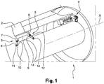
- the figure 1 illustrates a turbomachine 1 comprising a drive shaft of axis X, mounted on a pylon 2 of an aircraft using a suspension assembly 3.
- Said assembly comprises an upstream suspension device 4 and a downstream suspension device 5 , the downstream direction being oriented towards the direction of the flow of the air flow passing through the turbomachine in operation.
- the downstream suspension device 5 comprises a body 6 in the form of a beam comprising a first lateral end 7 and a second lateral end 8, located on either side of a vertical plane passing through the X axis. of the engine shaft of the turbomachine 1.
- the body 6 is fixed to the pylon 2, for example by screwing.
- Each lateral end 7, 8 of the beam 6 comprises a yoke, each yoke comprising two sides spaced apart from each other.
- the downstream suspension device 5 further comprises a first connecting rod 9 comprising a first end 10 articulated on the first lateral end 7 of the body 6, and a second end 11 articulated on a casing of the turbomachine 1, for example an exhaust housing of the turbomachine 1.
- the first end 10 of the first connecting rod 9 is engaged between the sides of the corresponding yoke and is articulated by means of a pivot pin, not shown, engaged without play in holes of the yoke and of the first end 10 of the first connecting rod 9.
- the terms “without play” mean that no specific play has been provided. Obviously, there may still be a small amount of play necessary for the assembly.
- the downstream suspension device 5 further comprises a second connecting rod 12 comprising a first end 13 articulated on the second lateral end 8 of the body 6, and a second end 14 articulated on said casing of the turbomachine.
- the first end 13 of the second connecting rod 12 is engaged between the sides of the corresponding yoke and is articulated by means of a pivot pin, not shown, engaged without play in holes of the yoke and of the first end 13 of the second connecting rod 12.
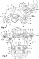
- the upstream suspension device 4 briefly visible at figure 1 , is better visible to figures 2 to 5 .
- This comprises a body 15 extending along a longitudinal axis A parallel to the axis X of the engine shaft of the turbomachine 1.
- the body 15 comprises a plate 16 extending in a plane parallel to the longitudinal axis A of the body 15, the body 15 comprising a protuberance 17 extending perpendicularly from the downstream zone of the plate 16, that is to say radially inwards with reference to the X axis of the engine shaft of the turbomachine 1.
- the plate 16 comprises a recessed area 18 and holes 19 serving for the engagement of screws allowing the fixing of the plate 16 to the pylon 2 of the aircraft.
- a yoke extends from said protuberance 17, said yoke being formed of two flanks 20 spaced apart from one another.
- the sidewalls 20 extend along the axis A of the body 15, upstream, and radially inward.
- the flanks 20 form an angle preferably between 15 ° and 45 ° relative to the plane of the plate 16.
- a beam 25, made integral with an upstream zone of the plate 16 comprises a first branch 21 and a second branch 22 which are located at the lateral edges of the plate 16 and extend in a plane perpendicular to the axis A of the body 15, on either side of the axis A.
- Each branch 21, 22 extends radially inward and laterally opposite the other branch.
- each branch 21, 22, that is to say the radially inner end of each branch 21, 22, comprises a yoke formed by two flanks 23, 24 offset from one another.
- the beam 25 has a middle part on which are formed a first yoke 26 and a second yoke 27, located on either side. of the axis A of the body 15. As before, each yoke 26, 27 is formed of two flanks offset with respect to one another.
- the suspension device further comprises a first link 28 and a second link 29 each comprising a first end 30, 31, or upper end, and a second end 32, 33, or lower end.
- the first end 30 of the first connecting rod 28 is engaged between the flanks 23 of the yoke of the first branch 21 and is articulated on said yoke by means of a pivot pin, not shown, engaged without play in holes 34 of said flanks 23 and of said first connecting rod 28.
- the first end 31 of the second connecting rod 29 is engaged between the flanks 24 of the yoke of the second branch 22 and is articulated on said yoke by means of a pivot pin, not shown , engaged without play in holes 35 of said flanks 24 and of said second connecting rod 29.
- the second ends 32, 33 of the first and second connecting rods 28, 29 are articulated on a casing of the turbomachine 1, by means of pivot pins not shown, engaged in holes 36 of the second ends 32, 33 of said connecting rods 28 , 29, in particular.
- Said pivot axes are oriented parallel to the axis of the body 15.
- the upstream suspension device 4 further comprises a third connecting rod 37 comprising a first branch 38 and a second branch 39, said branches 38, 39 being arranged together so as to form a V.
- Said branches 38, 39 each have a first end 40 or lower end, common to said branches 38, 39, each branch 38, 39 comprising a second end 41, 42 ( figure 4 ), or upper end.
- the first common end 40 is articulated on the casing of the turbomachine 1, by means of a pivot pin engaged without play in a hole 43 of the first end 40 in particular.
- Said pivot axis is parallel to the axis of the body 15.
- the second end 41 of the first branch 38 is articulated with play on the first yoke 26 of the middle part of the beam 25, by by means of a pivot pin without play engaged in holes 44 of the second end 41 of the first branch 38 and of the sides of the first yoke 26 of the middle part of the beam 25.
- the second end 42 of the second branch 39 is articulated with play on the second yoke 27 of the middle part of the beam 25, by means of a pivot pin engaged without play in holes of the second end 42 of the second branch 39 and the sides of the second yoke 27 of the middle part of the beam 25.
- pivot axes are parallel to the axis of the body 15.
- the upstream suspension device 4 also comprises a lifter 45.
- the lifter 45 extends along an axis perpendicular to the axis of the body 15 and comprises a first lateral end 46 and a second lateral end 47, located on either side. of the axis of the body 15, and a median zone 48.
- the median zone 48 of the beam 45 is engaged between the sides 20 of the yoke of the protuberance 17 of the body 15 and is mounted articulated in said yoke by means of 'a pivot axis, not shown, engaged without play in holes 49 of said sides of the yoke and of the middle zone 48.
- the pivot axis is inclined with respect to the vertical axis, that is to say l 'axis perpendicular to the plane of the plate 16, at an angle preferably between 15 ° and 45 °.
- the recessed zone 18 of the plate 16 is located opposite the articulation of the lifter 45 on the body 15.
- the recessed zone 18 is intended to allow the passage of a tool.
- the lifter 45 further comprises a first finger 50 and a second finger 51 extending respectively downstream from the first lateral end 46 and from the second lateral end 47 of the lifter 45.
- a first force-taking axis 52 is engaged without play in the plate 16 and is engaged with play in the first finger 50 of the lifter 45.
- a second force-taking pin 53 is engaged without play in the plate 16 and is engaged with play in the second finger 51 of the lifter 45.
- Each force-absorbing pin 52, 53 comprises an enlarged head 54 resting on the upper surface of the plate 16, a first threaded zone cooperating with a first nut 55, and a second threaded zone cooperating with a second nut 56.
- the first threaded zone has a larger diameter than the second threaded zone.
- the first nut 55 comes to bear on the lower surface 58 of the plate 16, the second nut 56 being screwed to the lower end of the corresponding force-taking axis 52, 53 so as to prevent the removal of the lifter 45. .
- the upstream suspension device 4 further comprises a fourth connecting rod 59 and a fifth connecting rod 60, rectilinear, each comprising a first end 61, 62 and a second end 63, 64 ( figure 4 ).
- Each end 61, 62, 63, 64 has a yoke comprising two sides spaced apart from one another.
- the yoke of the first end 61 of the fourth connecting rod 59 is mounted articulated on the first lateral end 46 of the lifter 45, by means of a pivot pin not shown, engaged without play in holes of the corresponding yoke and of the yoke. spreader 45.
- the yoke of the first end 62 of the fifth connecting rod 60 is mounted articulated on the second lateral end 47 of the yoke 45, by means of a pivot pin, not shown, engaged without play in the holes of the yoke. and of the lifter 45.
- Said pivot axes are perpendicular to the plane of the lifter 45, that is to say they are inclined with respect to the vertical axis, by an angle preferably between 15 ° and 45 °.
- the second ends 63, 64 of the connecting rods 59, 60 are articulated on the casing of the turbomachine 1, by means of pivot pins, not shown, engaged in holes of the corresponding yokes in particular.
- the articulation zones of the first and second connecting rods 28, 29 on the body 15 are offset laterally or circumferentially with respect to one another on either side of the axis of the body 15, the seconds ends 63, 64 of the fourth and fifth connecting rods 59, 60 being situated circumferentially between the articulation zones of the first and second connecting rods 28, 29.
- the term circumferential is defined with reference to the axis of the turbomachine 1.
- the first, second and third connecting rods 28, 29, 37 are located in the same transverse plane P perpendicular to the longitudinal axis A of the body ( figure 4 ).
- the points of intersection P1, P2 between the extension axes L1, L2 of the fourth and fifth connecting rods 59, 60 with said transverse plane P are thus situated circumferentially between the first connecting rod 28 and the second connecting rod 29, and on both sides 'other of the third link 37 in the transverse direction.
- the first and second connecting rods 28, 29 are designed to take up the lateral forces or the vertical forces.
- the lateral forces can in particular be exerted when a gust of wind comes to apply a lateral force on the turbomachine 1, that is to say a force directed horizontally, either in the direction of the fuselage of the airplane, or in the opposite direction. of the fuselage.
- the vertical forces are mainly due to the weight of the turbomachine 1.
- the third connecting rod 37 is designed to take up the torque exerted by the turbomachine 1, around its axis X.
- only one of the branches 38, 39 of the third connecting rod 37, namely the second branch 39, is suitable. in taking up the coupled generated by the turbomachine 1.
- the play between the first branch 38 and the body 15 is taken up and the first branch 38 is able to take up the torque generated by the turbomachine 1, replacing the second branch 39.
- the first branch 38 is thus able to form a security branch.
- the fourth and fifth connecting rods 59, 60 are designed to take up the thrust forces of the turbomachine 1, that is to say the forces directed along the X axis of the turbomachine 1 and of the body 15.
- Such a suspension device 4 makes it possible to meet the stress absorption constraints of the turbomachine 1 while offering a compact structure. Indeed, the particular orientation of the fourth and fifth connecting rods 59, 60 makes it possible to limit the size of the device 4 so as to facilitate the integration of the surrounding equipment on the turbomachine 1.
- the force-taking axes 52, 53 are able to hold the lifter 45 relative to the body 15 in the event of rupture of the fourth link 59 or of the fifth link 60.
- FIGS. 6 to 9 illustrate an upstream suspension device according to another embodiment of the invention, which differs from that explained above in that the force-taking axes 52, 53 are oriented parallel to the plane of the plate and are engaged with play in the fingers 50, 51 of the lifter 45, and without play in the protuberance, respectively on either side of the protuberance 17.
- Each force-absorbing axis 52, 53 comprises an enlarged head 54, resting on the finger 50, 51 corresponding.
- the force take-up pins 52, 53 are then without a nut. In the embodiment shown here, they can form an angle with respect to each other. In other words, the force-taking axes are not necessarily oriented along the same axis, perpendicular to the axis A of the body, although such a configuration can be envisaged.
- the force-taking axes 52, 53 are able to hold the lifter 45 relative to the body 15 in the event of rupture of the fourth link 59 or of the fifth link 60.
Description
- La présente invention concerne un dispositif de suspension pour une turbomachine, telle notamment qu'un turboréacteur ou un turbopropulseur d'avion.
- La demande de brevet
FR 2 867 155 FR 2 987 347 A1 - Les dispositifs de suspension ont pour fonction d'assurer la transmission des efforts mécaniques entre la turbomachine et la structure de l'avion. Ces efforts sont notamment la poussée générée par la turbomachine, orientée selon l'axe de la turbomachine noté X, les charges aérodynamiques latérales, orientées selon un axe noté Y et le poids de la turbomachine, orientée verticalement selon un axe noté Z. Les axes X, Y et Z sont orthogonaux deux à deux.
- Il existe actuellement un besoin de limiter les dimensions des turbomachines, tout en logeant un nombre important d'équipements. Afin de pouvoir répondre à ces différentes contraintes, il est nécessaire de réduire également l'encombrement des dispositifs de suspension.
- L'invention vise à répondre à cette problématique, de manière simple, fiable et peu onéreuse.
- A cet effet, la présente invention concerne un dispositif de suspension pour une turbomachine comportant :
- un corps destiné à être fixé à une partie fixe d'un aéronef, s'étendant selon un axe longitudinal prévu pour être parallèle à un axe d'arbre moteur de la turbomachine une fois le dispositif de suspension relié à la turbomachine,
- une première bielle et une deuxième bielle situées dans un même plan transversal perpendiculaire à l'axe longitudinal du corps, comportant chacune une première extrémité articulée par rapport au corps, et une seconde extrémité destinée à être articulée sur une première partie de la turbomachine,
- une troisième bielle articulée sur le corps entre les premières extrémités des première et deuxième bielles et destinée à être articulée sur la première partie de la turbomachine, entre les secondes extrémités des première et deuxième bielles,
- un palonnier articulé sur le corps,
- une quatrième bielle et une cinquième bielle s'étendant chacune selon un axe d'extension et comportant chacune une première extrémité articulée sur le palonnier et une seconde extrémité destinée à être articulée sur une deuxième partie de la turbomachine,
- les points d'intersection entre les axes d'extension des quatrième et cinquième bielles et le plan transversal étant situés entre la première bielle et la deuxième bielle, et de part et d'autre de la troisième bielle selon une direction transversale.
- Le terme circonférentiel et le terme radial sont définis par référence à l'axe du corps ou à l'axe de la turbomachine.
- Le corps est destiné à être fixé à une partie fixe d'un aéronef, telle par exemple qu'un mât ou qu'un pylône d'un avion.
- Les première et deuxième bielles peuvent être conçues pour reprendre les efforts latéraux ou les efforts verticaux. Les efforts latéraux peuvent notamment être exercés lorsqu'une rafale de vent vient appliquer un effort latéral sur la turbomachine, c'est-à-dire un effort dirigé horizontalement, soit en direction du fuselage de l'avion, soit à l'opposé du fuselage. Les efforts verticaux sont principalement dus au poids de la turbomachine.
- La troisième bielle peut être conçue pour reprendre le couple exercé par la turbomachine, autour de son axe.
- Les quatrième et cinquième bielles peuvent être conçues pour reprendre les efforts de poussée de la turbomachine, c'est-à-dire les efforts dirigés selon l'axe de la turbomachine et du corps.
- Un tel dispositif permet de remplir les contraintes de reprise d'efforts de la turbomachine tout en offrant une structure compacte. En effet, l'orientation particulière des quatrième et cinquième bielles permet de limiter l'encombrement de l'ensemble de manière à faciliter l'intégration des équipements environnants sur la turbomachine.
- Le dispositif de suspension peut comporter des moyens de reprise d'efforts reliant avec jeu le palonnier et le corps.
- Les moyens de reprise d'efforts peuvent être aptes à maintenir le palonnier par rapport au corps en cas de rupture de la quatrième bielle ou de la cinquième bielle.
- Les moyens de reprise d'efforts peuvent comporter :
- un premier axe de reprise d'efforts reliant avec jeu le corps et une première zone du palonnier, et
- un second axe de reprise d'efforts reliant avec jeu le corps et une seconde zone du palonnier, les premier et second axes de reprise d'efforts étant situés de part et d'autre de l'axe du corps.
- Le jeu peut être formé entre chaque axe de reprise d'efforts et le palonnier, et/ou entre chaque axe de reprise d'efforts et le corps.
- De préférence, le jeu est formé entre chaque axe de reprise d'efforts et la zone correspondante du palonnier.
- Le corps peut comporter une platine destinée à être fixée à la partie fixe de l'aéronef et parallèle à l'axe du corps, le corps comportant en outre une poutre solidaire d'une zone amont de la platine et sur laquelle les première et deuxième bielles sont articulées.
- Le corps peut comporter en outre une excroissance faisant saillie par rapport à une face de la platine du même côté que la poutre, solidairement à une zone aval de la platine.
- L'excroissance peut ainsi s'étendre verticalement vers le bas. La platine peut s'étendre dans un plan horizontal.
- La platine peut comporter une zone évidée située en regard de l'articulation du palonnier sur le corps. La zone évidée peut permettre le passage d'un outil.
- Les quatrième et cinquième bielles peuvent être courtes en ce qu'elle ne s'étendent pas au-delà du corps, et en particulier de la platine, en vue de dessus. En d'autre termes, la projection des quatrième et cinquième bielles dans le plan de la platine peut être majoritairement contenue dans la zone délimitée par la platine. Ceci permet de limiter l'encombrement du dispositif de suspension.
- Les axes de reprise d'efforts peuvent être montés dans la platine et peuvent s'étendre perpendiculairement à la platine.
- Les axes de reprise d'efforts peuvent être montés dans l'excroissance du corps et peuvent s'étendre en formant un angle compris entre 0° et 15° par rapport à un plan parallèle à la platine.
- Le palonnier peut être monté de façon articulé sur l'excroissance du corps.
- Le palonnier peut comporter au moins une ouverture médiane, l'excroissance du corps comportant au moins une ouverture, un axe d'articulation étant monté dans lesdites ouvertures du palonnier et de l'excroissance, par exemple sans jeu.
- La troisième bielle peut comporter une première branche et une seconde branche, lesdites branches étant agencées entre elles de manière à former un V, les deux branches comportant chacune une première extrémité commune auxdites branches, la première extrémité commune étant destinée à être articulée sur la première partie de la turbomachine, chaque branche comportant une seconde extrémité libre articulée sur le corps, la seconde extrémité de la première branche étant articulée avec jeu sur le corps, la seconde extrémité de la seconde branche étant articulée sans jeu sur le corps.
- Ainsi, en fonctionnement normal, seule l'une des branches, à savoir la seconde branche, est apte à reprendre le couplé généré par la turbomachine. En cas de rupture de ladite branche, le jeu est rattrapé et la première branche est apte à reprendre le couple généré par la turbomachine, en remplacement de la seconde branche.
- La première branche est ainsi apte à former une branche de sécurité.
- Les termes « sans jeu » signifient qu'aucun jeu spécifique de sécurité n'a pas été prévu. Bien évidemment, il peut tout de même exister un jeu faible nécessaire au montage.
- Le corps peut comporter une première branche et une seconde branche s'étendant de façon oblique l'une par rapport à l'autre, la première extrémité de la première bielle étant articulée sur la première branche du corps, par exemple sans jeu, la première extrémité de la seconde bielle étant articulée sur la seconde branche, par exemple sans jeu.
- L'invention peut également comporter un ensemble propulsif, pour aéronef, caractérisé en ce qu'il comprend une turbomachine dont une partie amont est suspendue à une partie fixe de l'aéronef par un dispositif de suspension du type précité, le dispositif de suspension appartenant audit ensemble propulsif, et en ce que la première bielle et la deuxième bielle sont disposées à l'amont du dispositif de suspension.
- Un carter au moins partiellement cylindrique s'étendant selon l'axe d'arbre moteur de la turbomachine peut former la première partie de la turbomachine sur laquelle sont articulées les première, deuxième, et troisième bielles, et un carter au moins partiellement annulaire s'étendant selon un plan perpendiculaire à l'axe d'arbre moteur de la turbomachine peut former la deuxième partie de la turbomachine sur laquelle sont articulées la quatrième bielle et la cinquième bielle.
- L'invention peut également concerner un aéronef comportant une partie fixe, telle par exemple qu'un pylône, une turbomachine, et des moyens de suspension de la turbomachine à ladite partie fixe, les moyens de suspension comportant au moins un dispositif de suspension du type précité ou au moins un ensemble propulsif du type précité.
- L'invention sera mieux comprise et d'autres détails, caractéristiques et avantages de l'invention apparaîtront à la lecture de la description suivante faite à titre d'exemple non limitatif en référence aux dessins annexés.
-
- la
figure 1 est une vue schématique illustrant une partie d'une turbomachine fixée à un pylône d'un aéronef, par l'intermédiaire d'un ensemble de suspension selon l'invention, - les
figures 2 à 5 sont des vues illustrant un dispositif de suspension selon une première forme de réalisation de l'invention, en particulier, - la
figure 2 est une vue en perspective du dispositif, - la
figure 3 est une vue en perspective, de côté, du dispositif, - la
figure 4 est une vue en perspective, de dessous, du dispositif, - la
figure 5 est une vue en perspective, de dessus, du dispositif, - les
figures 6 à 9 sont des vues illustrant un dispositif de suspension selon une seconde forme de réalisation de l'invention, en particulier, - la
figure 6 est une vue en perspective du dispositif, - la
figure 7 est une vue en perspective, de dessous, du dispositif, - la
figure 8 est une vue en perspective, de côté, du dispositif, - la
figure 9 est une vue en perspective, de dessus, du dispositif. - La
figure 1 illustre une turbomachine 1 comprenant un arbre moteur d'axe X, montée sur un pylône 2 d'un aéronef à l'aide d'un ensemble de suspension 3. Ledit ensemble comporte un dispositif de suspension amont 4 et un dispositif de suspension aval 5, la direction aval étant orientée vers la direction de l'écoulement du flux d'air traversant la turbomachine en fonctionnement. Le dispositif de suspension aval 5 comporte un corps 6 se présentant sous la forme d'une poutre comportant une première extrémité latérale 7 et une seconde extrémité latérale 8, situées de part et d'autre d'un plan vertical passant par l'axe X d'arbre moteur de la turbomachine 1. Le corps 6 est fixée au pylône 2, par exemple par vissage. Chaque extrémité latérale 7, 8 de la poutre 6 comporte une chape, chaque chape comportant deux flancs écartés l'un de l'autre. Le dispositif de suspension aval 5 comporte en outre une première bielle 9 comportant une première extrémité 10 articulée sur la première extrémité latérale 7 du corps 6, et une seconde extrémité 11 articulée sur un carter de la turbomachine 1, par exemple un carter d'échappement de la turbomachine 1. La première extrémité 10 de la première bielle 9 est engagée entre les flancs de la chape correspondante et est articulée par l'intermédiaire d'un axe de pivot non représenté, engagé sans jeu dans des trous de la chape et de la première extrémité 10 de la première bielle 9. Les termes « sans jeu » signifient qu'aucun jeu spécifique n'a été prévu. Bien évidemment, il peut tout de même exister un jeu faible nécessaire au montage. - Le dispositif de suspension aval 5 comporte de plus une seconde bielle 12 comportant une première extrémité 13 articulée sur la seconde extrémité latérale 8 du corps 6, et une seconde extrémité 14 articulée sur ledit carter de la turbomachine. Comme précédemment, la première extrémité 13 de la seconde bielle 12 est engagée entre les flancs de la chape correspondante et est articulée par l'intermédiaire d'un axe de pivot non représenté, engagé sans jeu dans des trous de la chape et de la première extrémité 13 de la seconde bielle 12.
- Le dispositif de suspension amont 4, visible de façon sommaire à la
figure 1 , est mieux visible auxfigures 2 à 5 . Celui-ci comporte un corps 15 s'étendant selon un axe longitudinal A parallèle à l'axe X d'arbre moteur de la turbomachine 1. Le corps 15 comporte une platine 16 s'étendant dans un plan parallèle à l'axe longitudinal A du corps 15, le corps 15 comportant une excroissance 17 s'étendant perpendiculairement depuis la zone aval de la platine 16, c'est-à-dire radialement vers l'intérieur par référence à l'axe X d'arbre moteur de la turbomachine 1. La platine 16 comporte une zone évidée 18 et des trous 19 servant à l'engagement de vis permettant la fixation de la platine 16 au pylône 2 de l'aéronef. - Une chape s'étend depuis ladite excroissance 17, ladite chape étant formée de deux flancs 20 écartés l'un de l'autre. Les flancs 20 s'étendent selon l'axe A du corps 15, vers l'amont, et radialement vers l'intérieur. Les flancs 20 forment un angle préférablement compris entre 15° et 45° par rapport au plan de la platine 16.
- Une poutre 25, rendue solidaire d'une zone amont de la platine 16, comprend une première branche 21 et une seconde branche 22 qui sont situées au niveau de bords latéraux de la platine 16 et s'étendent dans un plan perpendiculaire à l'axe A du corps 15, de part et d'autre de l'axe A. Chaque branche 21, 22 s'étend radialement vers l'intérieur et latéralement à l'opposé de l'autre branche.
- L'extrémité libre de chaque branche 21, 22, c'est-à-dire l'extrémité radialement interne de chaque branche 21, 22, comporte une chape formée de deux flancs 23, 24 décalés l'un de l'autre.
- La poutre 25 comporte une partie médiane sur laquelle sont formées une première chape 26 et une seconde chape 27, situées de part et d'autre de l'axe A du corps 15. Comme précédemment, chaque chape 26, 27 est formée de deux flancs décalés l'un par rapport à l'autre.
- Le dispositif de suspension comporte en outre une première bielle 28 et une seconde bielle 29 comportant chacune une première extrémité 30, 31, ou extrémité supérieure, et une seconde extrémité 32, 33, ou extrémité inférieure. La première extrémité 30 de la première bielle 28 est engagée entre les flancs 23 de la chape de la première branche 21 et est articulée sur ladite chape par l'intermédiaire d'un axe de pivot non représenté, engagé sans jeu dans des trous 34 desdits flancs 23 et de ladite première bielle 28. La première extrémité 31 de la seconde bielle 29 est engagée entre les flancs 24 de la chape de la seconde branche 22 et est articulée sur ladite chape par l'intermédiaire d'un axe de pivot non représenté, engagé sans jeu dans des trous 35 desdits flancs 24 et de ladite seconde bielle 29.
- Les secondes extrémités 32, 33 des première et seconde bielles 28, 29 sont articulées sur un carter de la turbomachine 1, par l'intermédiaire d'axes de pivot non représentés, engagés dans des trous 36 des secondes extrémités 32, 33 desdites bielles 28, 29, notamment. Lesdits axes de pivots sont orientés parallèlement à l'axe du corps 15.
- Le dispositif de suspension amont 4 comporte de plus une troisième bielle 37 comprenant une première branche 38 et une seconde branche 39, lesdites branches 38, 39 étant agencées entre elles de manière à former un V. Lesdites branches 38, 39 comportent chacune une première extrémité 40 ou extrémité inférieure, commune auxdites branches 38, 39, chaque branche 38, 39 comportant une seconde extrémité 41, 42 (
figure 4 ), ou extrémité supérieure. - La première extrémité commune 40 est articulée sur le carter de la turbomachine 1, par l'intermédiaire d'un axe de pivot engagé sans jeu dans un trou 43 de la première extrémité 40 notamment. Ledit axe de pivot est parallèle à l'axe du corps 15.
- La seconde extrémité 41 de la première branche 38 est articulée avec jeu sur la première chape 26 de la partie médiane de la poutre 25, par l'intermédiaire d'un axe de pivot sans jeu engagé dans des trous 44 de la seconde extrémité 41 de la première branche 38 et des flancs de la première chape 26 de la partie médiane de la poutre 25.
- La seconde extrémité 42 de la seconde branche 39 est articulée avec jeu sur la seconde chape 27 de la partie médiane de la poutre 25, par l'intermédiaire d'un axe de pivot engagé sans jeu dans des trous de la seconde extrémité 42 de la seconde branche 39 et des flancs de la seconde chape 27 de la partie médiane de la poutre 25.
- Les axes de pivot précités sont parallèles à l'axe du corps 15.
- Le dispositif de suspension amont 4 comporte également un palonnier 45. Le palonnier 45 s'étend selon un axe perpendiculaire à l'axe du corps 15 et comporte une première extrémité latérale 46 et une seconde extrémité latérale 47, situées de part et d'autre de l'axe du corps 15, et une zone médiane 48. La zone médiane 48 du palonnier 45 est engagée entre les flancs 20 de la chape de l'excroissance 17 du corps 15 et est montée articulée dans ladite chape par l'intermédiaire d'un axe de pivot non représenté, engagé sans jeu dans des trous 49 desdits flancs de la chape et de la zone médiane 48. L'axe de pivot est incliné par rapport à l'axe vertical, c'est-à-dire l'axe perpendiculaire au plan de la platine 16, d'un angle préférablement compris entre 15° et 45°.
- La zone évidée 18 de la platine 16 est située en regard de l'articulation du palonnier 45 sur le corps 15. La zone évidée 18 est destinée à permettre le passage d'un outil.
- Le palonnier 45 comporte en outre un premier doigt 50 et un second doigt 51 s'étendant respectivement vers l'aval depuis la première extrémité latérale 46 et depuis la seconde extrémité latérale 47 du palonnier 45. Un premier axe de reprise d'efforts 52 est engagé sans jeu dans la platine 16 et est engagé avec jeu dans le premier doigt 50 du palonnier 45. Un second axe de reprise d'efforts 53 est engagé sans jeu dans la platine 16 et est engagé avec jeu dans le second doigt 51 du palonnier 45.
- Chaque axe de reprise d'efforts 52, 53 comporte une tête élargie 54 en appui sur la surface supérieure de la platine 16, une première zone filetée coopérant avec un premier écrou 55, et une seconde zone filetée coopérant avec un second écrou 56. Pour des raisons de montage, la première zone filetée présente un diamètre plus important que la seconde zone filetée. Le premier écrou 55 vient en appui sur la surface inférieure 58 de la platine 16, le second écrou 56 étant vissé à l'extrémité inférieure de l'axe de reprise d'efforts 52, 53 correspondant de manière à empêcher le retrait du palonnier 45.
- Le dispositif de suspension amont 4 comporte en outre une quatrième bielle 59 et une cinquième bielle 60, rectilignes, comportant chacune une première extrémité 61, 62 et une deuxième extrémité 63, 64 (
figure 4 ). Chaque extrémité 61, 62, 63, 64 comporte une chape comprenant deux flancs écartés l'un de l'autre. - La chape de la première extrémité 61 de la quatrième bielle 59 est montée articulée sur la première extrémité latérale 46 du palonnier 45, par l'intermédiaire d'un axe de pivot non représenté, engagé sans jeu dans des trous de la chape correspondante et du palonnier 45. La chape de la première extrémité 62 de la cinquième bielle 60 est montée articulée sur la seconde extrémité latérale 47 du palonnier 45, par l'intermédiaire d'un axe de pivot non représenté, engagé sans jeu dans des trous de la chape correspondante et du palonnier 45. Lesdits axes de pivot sont perpendiculaires au plan du palonnier 45, c'est-à-dire sont inclinés par rapport à l'axe vertical, d'un angle préférablement compris entre 15° et 45°.
- Les secondes extrémités 63, 64 des bielles 59, 60 sont articulées sur le carter de la turbomachine 1, par l'intermédiaire d'axes de pivot non représentés, engagés dans des trous des chapes correspondantes notamment.
- Les zones d'articulation des première et seconde bielles 28, 29 sur le corps 15 sont décalées latéralement ou circonférentiellement l'une par rapport à l'autre de part et d'autre de l'axe du corps 15, les secondes extrémités 63, 64 des quatrième et cinquième bielles 59, 60 étant situées circonférentiellement entre les zones d'articulation des première et seconde bielles 28, 29. Le terme circonférentiel est défini par référence à l'axe de la turbomachine 1.
- Les première, seconde et troisième bielles 28, 29, 37 sont situées dans un même plan transversal P perpendiculaire à l'axe longitudinal A du corps (
figure 4 ). Les points d'intersection P1, P2 entre les axes d'extension L1, L2 des quatrième et cinquième bielles 59, 60 avec ledit plan transversal P sont ainsi situés circonférentiellement entre la première bielle 28 et la deuxième bielle 29, et de part et d'autre de la troisième bielle 37 selon la direction transversale. - Les première et deuxième bielles 28, 29 sont conçues pour reprendre les efforts latéraux ou les efforts verticaux. Les efforts latéraux peuvent notamment être exercés lorsqu'une rafale de vent vient appliquer un effort latéral sur la turbomachine 1, c'est-à-dire un effort dirigé horizontalement, soit en direction du fuselage de l'avion, soit à l'opposé du fuselage. Les efforts verticaux sont principalement dus au poids de la turbomachine 1.
- La troisième bielle 37 est conçue pour reprendre le couple exercé par la turbomachine 1, autour de son axe X. En fonctionnement normal, seule l'une des branches 38, 39 de la troisième bielle 37, à savoir la seconde branche 39, est apte à reprendre le couplé généré par la turbomachine 1. En cas de rupture de ladite seconde branche 39, le jeu entre la première branche 38 et le corps 15 est rattrapé et la première branche 38 est apte à reprendre le couple généré par la turbomachine 1, en remplacement de la seconde branche 39. La première branche 38 est ainsi apte à former une branche de sécurité.
- Les quatrième et cinquième bielles 59, 60 sont conçues pour reprendre les efforts de poussée de la turbomachine 1, c'est-à-dire les efforts dirigés selon l'axe X de la turbomachine 1 et du corps 15.
- Un tel dispositif de suspension 4 permet de remplir les contraintes de reprise d'efforts de la turbomachine 1 tout en offrant une structure compacte. En effet, l'orientation particulière des quatrième et cinquième bielles 59, 60 permet de limiter l'encombrement du dispositif 4 de manière à faciliter l'intégration des équipements environnants sur la turbomachine 1.
- Par ailleurs, les axes de reprise d'efforts 52, 53 sont aptes à maintenir le palonnier 45 par rapport au corps 15 en cas de rupture de la quatrième bielle 59 ou de la cinquième bielle 60.
- Les
figures 6 à 9 illustrent un dispositif de suspension amont selon une autre forme de réalisation de l'invention, qui diffère de celle exposée précédemment en ce que les axes de reprise d'efforts 52, 53 sont orientés parallèlement au plan de la platine et sont engagés avec jeu dans les doigts 50, 51 du palonnier 45, et sans jeu dans l'excroissance, respectivement de part et d'autre de l'excroissance 17. Chaque axe de reprise d'effort 52, 53 comporte une tête élargie 54, en appui sur le doigt 50, 51 correspondant. - Les axes de reprise d'effort 52, 53 sont alors dépourvus d'écrou. Dans la forme de réalisation représentée ici, ils peuvent former un angle l'un par rapport à l'autre. En d'autres termes, les axes de reprise d'efforts ne sont pas nécessairement orientés selon un même axe, perpendiculaire à l'axe A du corps bien qu'une telle configuration puisse être envisagée.
- Comme précédemment, les axes de reprise d'efforts 52, 53 sont aptes à maintenir le palonnier 45 par rapport au corps 15 en cas de rupture de la quatrième bielle 59 ou de la cinquième bielle 60.
Claims (11)
- Dispositif de suspension (4) pour une turbomachine (1) comportant :- un corps (15) destiné à être fixé à une partie fixe (2) d'un aéronef, s'étendant selon un axe longitudinal (A) prévu pour être parallèle à un axe (X) d'arbre moteur de la turbomachine (1) une fois le dispositif de suspension (4) relié à la turbomachine,- une première bielle (28) et une deuxième bielle (29) situées dans un même plan transversal (P) perpendiculaire à l'axe longitudinal (A) du corps, comportant chacune une première extrémité (30, 31) articulée par rapport au corps (15), et une seconde extrémité (32, 33) destinée à être articulée sur une première partie de la turbomachine (1),- une troisième bielle (37) articulée sur le corps (15) entre les premières extrémités (30, 31) des première et deuxième bielles (28, 29) et destinée à être articulée sur la première partie de la turbomachine (1), entre les secondes extrémités (32, 33) des première et deuxième bielles (28, 29),- un palonnier (45) articulé sur le corps (15),- une quatrième bielle (59) et une cinquième bielle (60) s'étendant chacune selon un axe d'extension (L1, L2) et comportant chacune une première extrémité (61, 62) articulée sur le palonnier (45) et une seconde extrémité (63, 64) destinée à être articulée sur une deuxième partie de la turbomachine (1),- les points d'intersection (P1, P2) entre les axes d'extension (L1, L2) des quatrième et cinquième bielles (59, 60) et le plan transversal (P) étant situés entre la première bielle (28) et la deuxième bielle (29), et de part et d'autre de la troisième bielle (37) selon une direction transversale.
- Dispositif de suspension (4) selon la revendication 1, caractérisé en ce qu'il comporte des moyens de reprise d'efforts (52, 53) reliant avec jeu le palonnier (45) et le corps (15).
- Dispositif de suspension (4) selon la revendication 2, caractérisé en ce que les moyens de reprise d'efforts comportent :- un premier axe de reprise d'efforts (52) reliant avec jeu le corps (15) et une première zone (50) du palonnier (45), et- un second axe de reprise d'efforts (53) reliant avec jeu le corps (15) et une seconde zone (51) du palonnier (45), les premier et second axes de reprise d'efforts (52, 53) étant situés de part et d'autre de l'axe (A) du corps (15).
- Dispositif de suspension (4) selon l'une des revendications 1 à 3, caractérisé en ce que le corps (15) comporte une platine (16) destinée à être fixée à la partie fixe (2) de l'aéronef et parallèle à l'axe (A) du corps (15), le corps (15) comportant en outre une poutre (25) solidaire d'une zone amont de la platine et sur laquelle les première et deuxième bielles (28, 29) sont articulées.
- Dispositif de suspension (4) selon la revendication 4, caractérisé en ce que le corps (15) comporte en outre une excroissance (17) faisant saillie par rapport à une face de la platine (16) du même côté que la poutre (25), solidairement à une zone aval de la platine.
- Dispositif de suspension (4) selon la revendication 4 ou 5 en combinaison avec la revendication 3, caractérisé en ce que les axes de reprise d'efforts (52, 53) sont montés dans la platine (16) et s'étendent perpendiculairement à la platine (16).
- Dispositif de suspension (4) selon la revendication 4 ou 5 en combinaison avec la revendication 3, caractérisé en ce que les axes de reprise d'efforts (52, 53) sont montés dans l'excroissance (17) du corps (15) et s'étendent en formant un angle compris entre 0° et 15° par rapport à un plan parallèle à la platine (16).
- Dispositif de suspension (4) selon l'une des revendications 5 à 7, caractérisé en ce que le palonnier (45) est monté de façon articulée sur l'excroissance (17) du corps (15).
- Dispositif de suspension (4) selon l'une des revendications 1 à 8, caractérisé en ce que la troisième bielle (37) comporte une première branche (38) et une seconde branche (39), lesdites branches (38, 39) étant agencées entre elles de manière à former un V, les deux branches (38, 39) comportant chacune une première extrémité (40) commune auxdites branches (38, 39), la première extrémité commune (40) étant destinée à être articulée sur la première partie de la turbomachine (1), chaque branche (38, 39) comportant une seconde extrémité libre (41, 42) articulée sur le corps (15), la seconde extrémité (41) de la première branche (38) étant articulée avec jeu sur le corps (15), la seconde extrémité (42) de la seconde branche (39) étant articulée sans jeu sur le corps (15).
- Ensemble propulsif pour aéronef, caractérisé en ce qu'il comprend une turbomachine (1) dont une partie amont est suspendue à une partie fixe (2) de l'aéronef par un dispositif de suspension (4) selon l'une des revendications 1 à 9, le dispositif de suspension (4) appartenant audit ensemble propulsif, et en ce que la première bielle (28) et la deuxième bielle (29) sont disposées à l'amont du dispositif de suspension.
- Ensemble propulsif selon la revendication 10, caractérisé en ce qu'un carter au moins partiellement cylindrique s'étendant selon l'axe (X) d'arbre moteur de la turbomachine forme la première partie de la turbomachine sur laquelle sont articulées les première, deuxième, et troisième bielles (28, 29, 37), et en ce qu'un carter au moins partiellement annulaire s'étendant selon un plan perpendiculaire à l'axe (X) d'arbre moteur de la turbomachine forme la deuxième partie de la turbomachine sur laquelle sont articulées la quatrième bielle (59) et la cinquième bielle (60).
Applications Claiming Priority (2)
| Application Number | Priority Date | Filing Date | Title |
|---|---|---|---|
| FR1762663A FR3075175B1 (fr) | 2017-12-20 | 2017-12-20 | Dispositif de suspension |
| PCT/FR2018/053307 WO2019122634A1 (fr) | 2017-12-20 | 2018-12-14 | Dispositif de suspension |
Publications (2)
| Publication Number | Publication Date |
|---|---|
| EP3728039A1 EP3728039A1 (fr) | 2020-10-28 |
| EP3728039B1 true EP3728039B1 (fr) | 2021-09-08 |
Family
ID=61258465
Family Applications (1)
| Application Number | Title | Priority Date | Filing Date |
|---|---|---|---|
| EP18833942.8A Active EP3728039B1 (fr) | 2017-12-20 | 2018-12-14 | Dispositif de suspension |
Country Status (5)
| Country | Link |
|---|---|
| US (1) | US11440670B2 (fr) |
| EP (1) | EP3728039B1 (fr) |
| CN (1) | CN111511644B (fr) |
| FR (1) | FR3075175B1 (fr) |
| WO (1) | WO2019122634A1 (fr) |
Families Citing this family (1)
| Publication number | Priority date | Publication date | Assignee | Title |
|---|---|---|---|---|
| US11708169B2 (en) * | 2020-12-14 | 2023-07-25 | Spirit Aerosystems, Inc. | Thrust load reaction assembly |
Family Cites Families (15)
| Publication number | Priority date | Publication date | Assignee | Title |
|---|---|---|---|---|
| US5649417A (en) * | 1995-03-24 | 1997-07-22 | The Boeing Company | Fail-safe engine mount system |
| US6330995B1 (en) * | 2000-02-29 | 2001-12-18 | General Electric Company | Aircraft engine mount |
| FR2867155B1 (fr) * | 2004-03-08 | 2007-06-29 | Snecma Moteurs | Suspension d'un moteur a la structure d'un avion |
| FR2883839B1 (fr) * | 2005-03-29 | 2007-06-29 | Snecma Moteurs Sa | Suspension arriere de turboreacteur |
| FR2903382B1 (fr) * | 2006-07-10 | 2008-10-10 | Airbus France Sas | Dispositif d'accrochage d'un moteur d'aeronef comportant deux bielles de reprise de poussee a emboitement transversal |
| FR2918644B1 (fr) * | 2007-07-09 | 2009-10-23 | Airbus France Sas | Mat d'accrochage de moteur pour aeronef disposant d'un palonnier articule en quatre points. |
| FR2925016B1 (fr) * | 2007-12-12 | 2010-06-18 | Snecma | Suspension d'un turboreacteur a un aeronef |
| WO2011159671A1 (fr) * | 2010-06-14 | 2011-12-22 | Lord Corporation | Système et procédés de montage d'un moteur d'hélicoptère |
| FR2981046B1 (fr) * | 2011-10-06 | 2013-10-25 | Aircelle Sa | Ensemble propulsif d'aeronef |
| FR2987347B1 (fr) * | 2012-02-28 | 2014-12-19 | Snecma | Piece d'accrochage pour une suspension arriere d'un turbomoteur a un pylone d'aeronef et suspension comprenant une telle piece d'accrochage. |
| US9217337B2 (en) * | 2012-05-10 | 2015-12-22 | United Technologies Corporation | Adjustable engine mount |
| CN103101628B (zh) * | 2013-02-06 | 2015-05-27 | 中国商用飞机有限责任公司 | 一种与飞机吊挂一体化的前安装节 |
| CA2916522C (fr) * | 2013-07-29 | 2021-05-11 | Bombardier Inc. | Procede de fixation d'un ensemble groupe propulseur et mat pre-assemble sur un avion |
| FR3026137B1 (fr) * | 2014-09-22 | 2019-03-15 | Safran Aircraft Engines | Element pour une turbomachine, telle par exemple qu'un turboreacteur ou un turbopropulseur d'avion |
| CN110182373B (zh) * | 2015-01-07 | 2023-01-10 | 洛德公司 | 用于飞行器发动机安装架的轴承组件 |
-
2017
- 2017-12-20 FR FR1762663A patent/FR3075175B1/fr not_active Expired - Fee Related
-
2018
- 2018-12-14 US US16/956,494 patent/US11440670B2/en active Active
- 2018-12-14 CN CN201880083085.0A patent/CN111511644B/zh active Active
- 2018-12-14 EP EP18833942.8A patent/EP3728039B1/fr active Active
- 2018-12-14 WO PCT/FR2018/053307 patent/WO2019122634A1/fr unknown
Also Published As
| Publication number | Publication date |
|---|---|
| US20210094695A1 (en) | 2021-04-01 |
| FR3075175A1 (fr) | 2019-06-21 |
| CN111511644B (zh) | 2023-06-27 |
| CN111511644A (zh) | 2020-08-07 |
| FR3075175B1 (fr) | 2019-12-13 |
| WO2019122634A1 (fr) | 2019-06-27 |
| EP3728039A1 (fr) | 2020-10-28 |
| US11440670B2 (en) | 2022-09-13 |
Similar Documents
| Publication | Publication Date | Title |
|---|---|---|
| EP2139768B1 (fr) | Mat d'accrochage de moteur pour aeronef disposant d'une attache moteur arriere pourvue d'un ecrou a barillet | |
| EP1773660B1 (fr) | Ensemble moteur pour aeronef | |
| EP1896326B1 (fr) | Attache moteur pour aeronef destinee a etre interposee entre un moteur et un mat d'accrochage | |
| EP2142430B1 (fr) | Dispositif d'accrochage de moteur d'aeronef et aeronef comportant au moins un tel dispositif | |
| EP2170704B1 (fr) | Dispositif d'accrochage de moteur d'aeronef et procede de montage d'un moteur d'aeronef au moyen d'un tel dispositif | |
| EP2185413B1 (fr) | Berceau de support de capot de soufflante monte sur le mât d'accrochage et sur l'entree d'air de la nacelle | |
| EP2137072B1 (fr) | Dispositif d'accrochage de moteur d'aeronef et aeronef comportant au moins un tel dispositif | |
| EP2754612B1 (fr) | Manille à trois points à capacité de filtrage de vibrations et attache moteur d'aéronef équipée d'une telle manille | |
| EP1231138A1 (fr) | Dispositif d'accrochage d'un moteur sur un aéronef | |
| EP1136355A1 (fr) | Dispositif de reprise de poussée apte à relier un turbomoteur et un mât d'aéronef | |
| EP2167384A1 (fr) | Mât d'accrochage de moteur pour aéronef disposant d'une poutre d'attache moteur arrière formant palonnier | |
| FR2931800A1 (fr) | Dispositif de reprise des efforts de poussee pour mat d'accrochage de moteur d'aeronef, comprenant des bielles laterales a butees de palonnier integrees | |
| EP3483069A1 (fr) | Systeme d'attache moteur d'aeronef | |
| FR2917710A1 (fr) | Platine de fixation et longeron de manutention d'ensemble propulsif monobloc d'un aeronef | |
| EP2522575B1 (fr) | Dispositif d'accrochage d'un moteur d'aéronef, comprenant des cales de serrage d'attache moteur à effet de coin | |
| CA2960869C (fr) | Procede et dispositif de montage d'un moteur sur un pylone d'aeronef | |
| EP3505448B1 (fr) | Ensemble pour aeronef comprenant une structure primaire de mat d'accrochage fixee a un caisson de voilure par des attaches presentant un encombrement reduit dans la zone de bord d'attaque | |
| FR3058986A1 (fr) | Attache arriere d'un moteur d'aeronef comportant des temoins de rupture | |
| FR3073205A1 (fr) | Attache moteur d'un moteur d'aeronef | |
| FR2981046A1 (fr) | Ensemble propulsif d'aeronef | |
| EP3505439A1 (fr) | Ensemble pour aeronef comprenant une structure primaire de mat d'accrochage fixee a un caisson de voilure par des attaches presentant un encombrement reduit dans la zone de bord d'attaque | |
| FR2887850A1 (fr) | Dispositif d'accrochage d'un moteur interpose entre une voilure d'aeronef et ledit moteur | |
| FR2887522A1 (fr) | Ensemble pour aeronef comprenant un element de voilure ainsi qu'un mat d'accrochage | |
| EP3486174B1 (fr) | Attache moteur arriere pour un moteur d'aeronef | |
| EP3728039B1 (fr) | Dispositif de suspension |
Legal Events
| Date | Code | Title | Description |
|---|---|---|---|
| STAA | Information on the status of an ep patent application or granted ep patent |
Free format text: STATUS: UNKNOWN |
|
| STAA | Information on the status of an ep patent application or granted ep patent |
Free format text: STATUS: THE INTERNATIONAL PUBLICATION HAS BEEN MADE |
|
| PUAI | Public reference made under article 153(3) epc to a published international application that has entered the european phase |
Free format text: ORIGINAL CODE: 0009012 |
|
| STAA | Information on the status of an ep patent application or granted ep patent |
Free format text: STATUS: REQUEST FOR EXAMINATION WAS MADE |
|
| 17P | Request for examination filed |
Effective date: 20200618 |
|
| AK | Designated contracting states |
Kind code of ref document: A1 Designated state(s): AL AT BE BG CH CY CZ DE DK EE ES FI FR GB GR HR HU IE IS IT LI LT LU LV MC MK MT NL NO PL PT RO RS SE SI SK SM TR |
|
| AX | Request for extension of the european patent |
Extension state: BA ME |
|
| DAV | Request for validation of the european patent (deleted) | ||
| DAX | Request for extension of the european patent (deleted) | ||
| GRAP | Despatch of communication of intention to grant a patent |
Free format text: ORIGINAL CODE: EPIDOSNIGR1 |
|
| STAA | Information on the status of an ep patent application or granted ep patent |
Free format text: STATUS: GRANT OF PATENT IS INTENDED |
|
| INTG | Intention to grant announced |
Effective date: 20210531 |
|
| GRAS | Grant fee paid |
Free format text: ORIGINAL CODE: EPIDOSNIGR3 |
|
| GRAA | (expected) grant |
Free format text: ORIGINAL CODE: 0009210 |
|
| STAA | Information on the status of an ep patent application or granted ep patent |
Free format text: STATUS: THE PATENT HAS BEEN GRANTED |
|
| AK | Designated contracting states |
Kind code of ref document: B1 Designated state(s): AL AT BE BG CH CY CZ DE DK EE ES FI FR GB GR HR HU IE IS IT LI LT LU LV MC MK MT NL NO PL PT RO RS SE SI SK SM TR |
|
| REG | Reference to a national code |
Ref country code: GB Ref legal event code: FG4D Free format text: NOT ENGLISH |
|
| REG | Reference to a national code |
Ref country code: CH Ref legal event code: EP Ref country code: AT Ref legal event code: REF Ref document number: 1428387 Country of ref document: AT Kind code of ref document: T Effective date: 20210915 |
|
| REG | Reference to a national code |
Ref country code: DE Ref legal event code: R096 Ref document number: 602018023419 Country of ref document: DE |
|
| REG | Reference to a national code |
Ref country code: IE Ref legal event code: FG4D Free format text: LANGUAGE OF EP DOCUMENT: FRENCH |
|
| REG | Reference to a national code |
Ref country code: SE Ref legal event code: TRGR |
|
| REG | Reference to a national code |
Ref country code: LT Ref legal event code: MG9D |
|
| REG | Reference to a national code |
Ref country code: NL Ref legal event code: MP Effective date: 20210908 |
|
| PG25 | Lapsed in a contracting state [announced via postgrant information from national office to epo] |
Ref country code: RS Free format text: LAPSE BECAUSE OF FAILURE TO SUBMIT A TRANSLATION OF THE DESCRIPTION OR TO PAY THE FEE WITHIN THE PRESCRIBED TIME-LIMIT Effective date: 20210908 Ref country code: ES Free format text: LAPSE BECAUSE OF FAILURE TO SUBMIT A TRANSLATION OF THE DESCRIPTION OR TO PAY THE FEE WITHIN THE PRESCRIBED TIME-LIMIT Effective date: 20210908 Ref country code: FI Free format text: LAPSE BECAUSE OF FAILURE TO SUBMIT A TRANSLATION OF THE DESCRIPTION OR TO PAY THE FEE WITHIN THE PRESCRIBED TIME-LIMIT Effective date: 20210908 Ref country code: BG Free format text: LAPSE BECAUSE OF FAILURE TO SUBMIT A TRANSLATION OF THE DESCRIPTION OR TO PAY THE FEE WITHIN THE PRESCRIBED TIME-LIMIT Effective date: 20211208 Ref country code: LT Free format text: LAPSE BECAUSE OF FAILURE TO SUBMIT A TRANSLATION OF THE DESCRIPTION OR TO PAY THE FEE WITHIN THE PRESCRIBED TIME-LIMIT Effective date: 20210908 Ref country code: HR Free format text: LAPSE BECAUSE OF FAILURE TO SUBMIT A TRANSLATION OF THE DESCRIPTION OR TO PAY THE FEE WITHIN THE PRESCRIBED TIME-LIMIT Effective date: 20210908 Ref country code: NO Free format text: LAPSE BECAUSE OF FAILURE TO SUBMIT A TRANSLATION OF THE DESCRIPTION OR TO PAY THE FEE WITHIN THE PRESCRIBED TIME-LIMIT Effective date: 20211208 |
|
| REG | Reference to a national code |
Ref country code: AT Ref legal event code: MK05 Ref document number: 1428387 Country of ref document: AT Kind code of ref document: T Effective date: 20210908 |
|
| PG25 | Lapsed in a contracting state [announced via postgrant information from national office to epo] |
Ref country code: LV Free format text: LAPSE BECAUSE OF FAILURE TO SUBMIT A TRANSLATION OF THE DESCRIPTION OR TO PAY THE FEE WITHIN THE PRESCRIBED TIME-LIMIT Effective date: 20210908 Ref country code: GR Free format text: LAPSE BECAUSE OF FAILURE TO SUBMIT A TRANSLATION OF THE DESCRIPTION OR TO PAY THE FEE WITHIN THE PRESCRIBED TIME-LIMIT Effective date: 20211209 |
|
| PG25 | Lapsed in a contracting state [announced via postgrant information from national office to epo] |
Ref country code: AT Free format text: LAPSE BECAUSE OF FAILURE TO SUBMIT A TRANSLATION OF THE DESCRIPTION OR TO PAY THE FEE WITHIN THE PRESCRIBED TIME-LIMIT Effective date: 20210908 |
|
| PG25 | Lapsed in a contracting state [announced via postgrant information from national office to epo] |
Ref country code: IS Free format text: LAPSE BECAUSE OF FAILURE TO SUBMIT A TRANSLATION OF THE DESCRIPTION OR TO PAY THE FEE WITHIN THE PRESCRIBED TIME-LIMIT Effective date: 20220108 Ref country code: SM Free format text: LAPSE BECAUSE OF FAILURE TO SUBMIT A TRANSLATION OF THE DESCRIPTION OR TO PAY THE FEE WITHIN THE PRESCRIBED TIME-LIMIT Effective date: 20210908 Ref country code: SK Free format text: LAPSE BECAUSE OF FAILURE TO SUBMIT A TRANSLATION OF THE DESCRIPTION OR TO PAY THE FEE WITHIN THE PRESCRIBED TIME-LIMIT Effective date: 20210908 Ref country code: RO Free format text: LAPSE BECAUSE OF FAILURE TO SUBMIT A TRANSLATION OF THE DESCRIPTION OR TO PAY THE FEE WITHIN THE PRESCRIBED TIME-LIMIT Effective date: 20210908 Ref country code: PT Free format text: LAPSE BECAUSE OF FAILURE TO SUBMIT A TRANSLATION OF THE DESCRIPTION OR TO PAY THE FEE WITHIN THE PRESCRIBED TIME-LIMIT Effective date: 20220110 Ref country code: PL Free format text: LAPSE BECAUSE OF FAILURE TO SUBMIT A TRANSLATION OF THE DESCRIPTION OR TO PAY THE FEE WITHIN THE PRESCRIBED TIME-LIMIT Effective date: 20210908 Ref country code: NL Free format text: LAPSE BECAUSE OF FAILURE TO SUBMIT A TRANSLATION OF THE DESCRIPTION OR TO PAY THE FEE WITHIN THE PRESCRIBED TIME-LIMIT Effective date: 20210908 Ref country code: EE Free format text: LAPSE BECAUSE OF FAILURE TO SUBMIT A TRANSLATION OF THE DESCRIPTION OR TO PAY THE FEE WITHIN THE PRESCRIBED TIME-LIMIT Effective date: 20210908 Ref country code: CZ Free format text: LAPSE BECAUSE OF FAILURE TO SUBMIT A TRANSLATION OF THE DESCRIPTION OR TO PAY THE FEE WITHIN THE PRESCRIBED TIME-LIMIT Effective date: 20210908 Ref country code: AL Free format text: LAPSE BECAUSE OF FAILURE TO SUBMIT A TRANSLATION OF THE DESCRIPTION OR TO PAY THE FEE WITHIN THE PRESCRIBED TIME-LIMIT Effective date: 20210908 |
|
| REG | Reference to a national code |
Ref country code: DE Ref legal event code: R097 Ref document number: 602018023419 Country of ref document: DE |
|
| PLBE | No opposition filed within time limit |
Free format text: ORIGINAL CODE: 0009261 |
|
| STAA | Information on the status of an ep patent application or granted ep patent |
Free format text: STATUS: NO OPPOSITION FILED WITHIN TIME LIMIT |
|
| PG25 | Lapsed in a contracting state [announced via postgrant information from national office to epo] |
Ref country code: MC Free format text: LAPSE BECAUSE OF FAILURE TO SUBMIT A TRANSLATION OF THE DESCRIPTION OR TO PAY THE FEE WITHIN THE PRESCRIBED TIME-LIMIT Effective date: 20210908 Ref country code: DK Free format text: LAPSE BECAUSE OF FAILURE TO SUBMIT A TRANSLATION OF THE DESCRIPTION OR TO PAY THE FEE WITHIN THE PRESCRIBED TIME-LIMIT Effective date: 20210908 |
|
| REG | Reference to a national code |
Ref country code: CH Ref legal event code: PL |
|
| 26N | No opposition filed |
Effective date: 20220609 |
|
| REG | Reference to a national code |
Ref country code: BE Ref legal event code: MM Effective date: 20211231 |
|
| PG25 | Lapsed in a contracting state [announced via postgrant information from national office to epo] |
Ref country code: LU Free format text: LAPSE BECAUSE OF NON-PAYMENT OF DUE FEES Effective date: 20211214 Ref country code: IE Free format text: LAPSE BECAUSE OF NON-PAYMENT OF DUE FEES Effective date: 20211214 |
|
| PG25 | Lapsed in a contracting state [announced via postgrant information from national office to epo] |
Ref country code: BE Free format text: LAPSE BECAUSE OF NON-PAYMENT OF DUE FEES Effective date: 20211231 |
|
| PG25 | Lapsed in a contracting state [announced via postgrant information from national office to epo] |
Ref country code: LI Free format text: LAPSE BECAUSE OF NON-PAYMENT OF DUE FEES Effective date: 20211231 Ref country code: CH Free format text: LAPSE BECAUSE OF NON-PAYMENT OF DUE FEES Effective date: 20211231 |
|
| PGFP | Annual fee paid to national office [announced via postgrant information from national office to epo] |
Ref country code: IT Payment date: 20221122 Year of fee payment: 5 |
|
| PG25 | Lapsed in a contracting state [announced via postgrant information from national office to epo] |
Ref country code: CY Free format text: LAPSE BECAUSE OF FAILURE TO SUBMIT A TRANSLATION OF THE DESCRIPTION OR TO PAY THE FEE WITHIN THE PRESCRIBED TIME-LIMIT Effective date: 20210908 |
|
| PG25 | Lapsed in a contracting state [announced via postgrant information from national office to epo] |
Ref country code: HU Free format text: LAPSE BECAUSE OF FAILURE TO SUBMIT A TRANSLATION OF THE DESCRIPTION OR TO PAY THE FEE WITHIN THE PRESCRIBED TIME-LIMIT; INVALID AB INITIO Effective date: 20181214 |
|
| PG25 | Lapsed in a contracting state [announced via postgrant information from national office to epo] |
Ref country code: SI Free format text: LAPSE BECAUSE OF FAILURE TO SUBMIT A TRANSLATION OF THE DESCRIPTION OR TO PAY THE FEE WITHIN THE PRESCRIBED TIME-LIMIT Effective date: 20210908 |
|
| REG | Reference to a national code |
Ref country code: DE Ref legal event code: R079 Ref document number: 602018023419 Country of ref document: DE Free format text: PREVIOUS MAIN CLASS: B64D0027260000 Ipc: B64D0027400000 |
|
| PGFP | Annual fee paid to national office [announced via postgrant information from national office to epo] |
Ref country code: GB Payment date: 20231124 Year of fee payment: 6 |
|
| PGFP | Annual fee paid to national office [announced via postgrant information from national office to epo] |
Ref country code: SE Payment date: 20231121 Year of fee payment: 6 Ref country code: FR Payment date: 20231122 Year of fee payment: 6 Ref country code: DE Payment date: 20231121 Year of fee payment: 6 |
|
| PG25 | Lapsed in a contracting state [announced via postgrant information from national office to epo] |
Ref country code: MK Free format text: LAPSE BECAUSE OF FAILURE TO SUBMIT A TRANSLATION OF THE DESCRIPTION OR TO PAY THE FEE WITHIN THE PRESCRIBED TIME-LIMIT Effective date: 20210908 |