EP1058325A2 - Non-aqueous electrolyte battery - Google Patents
Non-aqueous electrolyte battery Download PDFInfo
- Publication number
- EP1058325A2 EP1058325A2 EP00111667A EP00111667A EP1058325A2 EP 1058325 A2 EP1058325 A2 EP 1058325A2 EP 00111667 A EP00111667 A EP 00111667A EP 00111667 A EP00111667 A EP 00111667A EP 1058325 A2 EP1058325 A2 EP 1058325A2
- Authority
- EP
- European Patent Office
- Prior art keywords
- positive
- active material
- electrode
- electrode active
- aqueous electrolyte
- Prior art date
- Legal status (The legal status is an assumption and is not a legal conclusion. Google has not performed a legal analysis and makes no representation as to the accuracy of the status listed.)
- Withdrawn
Links
Images



Classifications
-
- H—ELECTRICITY
- H01—ELECTRIC ELEMENTS
- H01M—PROCESSES OR MEANS, e.g. BATTERIES, FOR THE DIRECT CONVERSION OF CHEMICAL ENERGY INTO ELECTRICAL ENERGY
- H01M4/00—Electrodes
- H01M4/02—Electrodes composed of, or comprising, active material
- H01M4/36—Selection of substances as active materials, active masses, active liquids
- H01M4/48—Selection of substances as active materials, active masses, active liquids of inorganic oxides or hydroxides
- H01M4/50—Selection of substances as active materials, active masses, active liquids of inorganic oxides or hydroxides of manganese
- H01M4/505—Selection of substances as active materials, active masses, active liquids of inorganic oxides or hydroxides of manganese of mixed oxides or hydroxides containing manganese for inserting or intercalating light metals, e.g. LiMn2O4 or LiMn2OxFy
-
- H—ELECTRICITY
- H01—ELECTRIC ELEMENTS
- H01M—PROCESSES OR MEANS, e.g. BATTERIES, FOR THE DIRECT CONVERSION OF CHEMICAL ENERGY INTO ELECTRICAL ENERGY
- H01M10/00—Secondary cells; Manufacture thereof
- H01M10/05—Accumulators with non-aqueous electrolyte
- H01M10/052—Li-accumulators
-
- Y—GENERAL TAGGING OF NEW TECHNOLOGICAL DEVELOPMENTS; GENERAL TAGGING OF CROSS-SECTIONAL TECHNOLOGIES SPANNING OVER SEVERAL SECTIONS OF THE IPC; TECHNICAL SUBJECTS COVERED BY FORMER USPC CROSS-REFERENCE ART COLLECTIONS [XRACs] AND DIGESTS
- Y02—TECHNOLOGIES OR APPLICATIONS FOR MITIGATION OR ADAPTATION AGAINST CLIMATE CHANGE
- Y02E—REDUCTION OF GREENHOUSE GAS [GHG] EMISSIONS, RELATED TO ENERGY GENERATION, TRANSMISSION OR DISTRIBUTION
- Y02E60/00—Enabling technologies; Technologies with a potential or indirect contribution to GHG emissions mitigation
- Y02E60/10—Energy storage using batteries
Definitions
- the present invention relates to a non-aqueous electrolyte battery incorporating a positive-electrode active material constituted by a composite lithium oxide.
- the lithium secondary battery incorporates positive and negative electrodes, to which lithium ions can reversibly be doped/dedoped, and non-aqueous electrolytic solution.
- LiMnO 2 having a theoretical capacity equivalent to that of LiCoO 2 has energetically been studied as a candidate of the positive-electrode active material containing manganese. According to reports of studies in the early stage, high-temperature LiMnO 2 and low-temperature LiMnO 2 have been reported.
- High-temperature LiMnO 2 has first been reported by W. D. Johnston et al. (J. Am. Chem. Soc., 78, 325 (1956)). Then, R. Hoppe, G. Brachtel and M. Jansen (Z. Anorg. Allg. Chmie, 417, 1 (1975) have determined the structure. Low-temperature LiMnO 2 has first been reported by T. Ozuka, A. Ueda and T. Hirai (Chem. Express, Vol. 7, No. 3, 193 (1992)).
- Each of high-temperature LiMnO 2 and low-temperature LiMnO 2 has a structure incorporating orthorombic lattices and defined by space group Pmnm.
- the theoretical capacity of each of the high-temperature LiMnO 2 and low-temperature LiMnO 2 is about 300 mAh/g. The theoretical capacity cannot be realized when the charge/discharge conditions which are adapted to the present non-aqueous electrolyte batteries are employed.
- the charge capacity of high-temperature LiMnO 2 is 150 mAh/g and that of the low-temperature LiMnO 2 is 200 mAh/g.
- the initial discharge capacity of high-temperature LiMnO 2 is not higher than 50 mAh/g (2.0 V ⁇ V (Li/Li + ), while that of low-temperature LiMnO 2 is 190 mAh/g (2.0 V ⁇ V (Li/Li + )).
- the foregoing values are those measured when the current density is 100 ⁇ A/cm 2 or lower. To practically employ the foregoing manganese oxides, the foregoing values must be realized when the current density is 500 ⁇ A/cm 2 or higher. When the foregoing manganese oxide is used at the high-load current density, the discharge capacities of the high-temperature LiMnO 2 and the low-temperature LiMnO 2 are reduced to about 40 mAh/g and about 120 mAh/g, respectively.
- each material has a crystralline structure as shown in Fig. 1 that sheets each of which is constituted by Mn-O are laminated such that Li is introduced between the Mn-O sheets.
- the foregoing crystalline structure has the diffusion paths for Li formed into a zigzag shape. Thus, quick diffusion of Li cannot be observed.
- Another reason lies in that the high-temperature LiMnO 2 has high crsytallinity. Therefore, the electron resistance caused from impurity failure is low.
- low-temperature LiMnO 2 having low crystallinity encounters high resistance caused from impurity.
- LiMnO 2 encounters considerable IR drop owing to a high load, that is, a high current density. Therefore, great energy loss occurs. Under the foregoing circumstances, LiMnO 2 having a flat layer structure permitting quick diffusion of Li and exhibiting high crystallinity has been required.
- LiMnO 2 encounters change in the structure (formed into a spinel structure) during the charging process, causing the discharge capacity to be reduced.
- LiMnO 2 of the type reported by Armstrong et al. encounters considerable change in the structure during the charging process. Thus, a satisfactorily large discharge capacity cannot be obtained.
- LiMn 0.75 Al 0.25 O 2 is not thermodynamically unstable as compared with LiMnO 2 .
- change in the structure does not considerably occur.
- formation of a solid solution of Al which is electrochemically inactive results in reduction in the capacity.
- an object of the present invention to provide a non-aqueous electrolyte battery free from considerable change in the structure of a positive-electrode active material thereof and capable of enlarging the capacity thereof.
- a non-aqueous electrolyte battery comprising: a positive electrode containing a positive-electrode active material; a negative electrode containing a negative-electrode active material to which Li can be doped/dedoped; and a non-aqueous electrolyte disposed between the positive electrode and the negative electrode and containing non-aqueous solvent and an electrolyte, wherein a material expressed by general formula LiMn 1-y Al y O 2 (0.06 ⁇ y ⁇ 0.25) is contained as the positive-electrode active material and LiMn 1-y Al y O 2 has a crystalline structure expressed by spatial group C2/m.
- the non-aqueous electrolyte battery according to the present invention and incorporating a layered compound expressed by LiMn 1-y Al y O 2 is able to enhance diffusion of lithium ions. Since the non-aqueous electrolyte battery according to the present invention is structured such that the value of y of LiMn 1-y Al y O 2 is specified, deterioration in the electric conductivity can be prevented. Moreover, thermal stability of the crystalline structure can be improved.
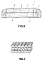
- Non-aqueous electrolyte battery 1 incorporates a negative electrode 2, a negative electrode can 3 for accommodating the negative electrode 2, a positive electrode 4, a positive electrode can 5 for accommodating the positive electrode 4, a separator 6 disposed between the positive electrode 4 and the negative electrode 2 and an insulating gasket 7.
- Non-aqueous electrolytic solution is enclosed in the negative electrode can 3 and the positive electrode can 5.
- the negative electrode 2 is constituted by, for example, metal lithium foil, serving as a negative-electrode active material.
- the negative-electrode active material is a material to which lithium can be doped/dedoped
- a negative-electrode active material layer containing the negative-electrode active material is formed on a negative-electrode collector of the negative electrode 2.
- the negative-electrode collector is constituted by, for example, nickel foil.
- lithium metal foil may be used as the negative electrode 2.
- lithium As the negative-electrode active material to which lithium can be doped/dedoped, lithium, a lithium alloy or a conductive polymer or a layered compound (a carbon material or a metal oxide) containing lithium doped thereto is employed.
- the negative-electrode active material layer contains a binder which may be a known resin material which is usually used as a binder for a negative-electrode active material layer of a non-aqueous electrolyte battery of the foregoing type.
- the negative electrode can 3 accommodates the negative electrode 2 and serves as an external negative electrode of the non-aqueous electrolyte battery 1.
- the positive electrode 4 has a structure that a positive-electrode active material layer containing a positive-electrode active material and a binder is formed on a positive electrode collector.
- the positive-electrode collector is constituted by, for example, aluminum foil.
- the non-aqueous electrolyte battery according to this embodiment incorporates the positive-electrode active material constituted by a compound expressed by general formula LiMn 1-y Al y O 2 .
- the compound LiMn 1-y Al y O 2 has a crystalline structure expressed by a spatial group C2/m. Al is substituted for a portion of Mn of LiMnO 2 to form solid solution of Al so that LiMn 1-y Al y O 2 is obtained.
- the thermal stability of the crystalline structure during the charging step can be improved. Since the thermal stability of the crystalline structure during the charging step can be improved, spinel transition during the charging step can be prevented. Thus, an effect can be obtained in that the discharge capacity can been enlarged.
- the value of y in LiMn 1-y Al y O 2 satisfies a range 0.06 ⁇ y ⁇ 0.25.
- y ⁇ 0.06 a satisfactory effect for improving the thermal stability of the crystalline structure of the compound cannot be obtained.
- y ⁇ 0.25 a ratio of Al which is electrochemically inactive is raised.
- the electronic conductivity deteriorates, causing the polarization of LiMn 1-y Al y O 2 to be enhanced.
- the capacity is reduced. Since the ratio of Al is raised, the quantity of Mn or Mn-O bonds is undesirably reduced. Therefore, the value of y is made to satisfy 0.06 ⁇ y ⁇ 0.25 so that the thermal stability of the crystalline structure is improved and the discharge capacity is enlarged without any deterioration in the electric conductivity.
- LiMn 1-y Al y O 2 has the crystalline structure expressed by spatial group C2/m.
- the crystalline structure expressed by the spatial group C2/m has a shape as shown in Fig. 3 that flat sheet layers constituted by Mn-O are laminated and Li is introduced between the Mn-O sheet layers.
- the foregoing laminate structure causes diffusion paths for lithium ions to be two-dimensional shape. As a result, lithium ions can efficiently and quickly be dispersed.
- Example 9 the inventors has prepared LiMn 0.95 Al 0.05 O 2 in Example 9. Moreover, description has been made that "the X-ray diffraction pattern of obtained powder was examined, thus resulting in that a pattern similar to that of composite oxide of lithium and manganese (zigzag shape LiMnO 2 reported before 1995) was confirmed.
- the inventor of the present invention has detected a fact that LiMn 1-y Al y O 2 has the layered structure expressed by the spatial group C2/m. Moreover, the diffusion paths for lithium ions are formed into two-dimension shape. Thus, lithium ions can quickly be dispersed.
- the effect of the present invention is caused from a fact that the crystalline structure of LiMn 1-y Al y O 2 has a flat layered shape and the diffusion paths for lithium ions are formed into two-dimensional shape.
- the fact that LiMn 1-y Al y O 2 has the flat layered structure expressed by the spatial group C2/m is confirmed owing to the X-ray diffraction pattern of the foregoing compound measured by the inventor of the present invention as described in examples to be described later.
- the inventor of the above-mentioned disclosure has not recognized the fact that the LiMn 0.95 Al 0.05 O 2 has the layered structure. As described above, the effect of the present invention is caused from a fact that the crystalline structure of LiMn 1-y Al y O 2 has a flat layered shape. Therefore, the foregoing fact according to the present invention is not included in the previous invention.
- the binder to be contained in the positive electrode mix may be a known binder which is usually employed in the positive electrode mix of a battery of the foregoing type. Moreover, a known additive may be added to the positive electrode mix.
- the positive electrode can 5 accommodates the positive electrode 4 and serves as the external positive electrode of the non-aqueous electrolyte battery 1.
- the separator 6 insulates the positive electrode 4 and the negative electrode 2 from each other.
- the separator 6 may be made of a known material which is usually employed as the material of the separator of the non-aqueous electrolyte battery of the foregoing type.
- a polymer film of, for example, polypropylene is employed.
- the insulating gasket 7 is included in the negative electrode can 3 so as to be integrated with the negative electrode can 3.
- the insulating gasket 7 prevents leakage of non-aqueous electrolytic solution enclosed in the negative electrode can 3 and the positive electrode can 5.
- the non-aqueous electrolytic solution is prepared by dissolving the electrolyte in non-aqueous solvent.
- the electrolyte may be a known electrolyte which is usually employed in a battery of the foregoing type.
- the material of the electrolyte is exemplified by lithium salt, such as LiClO 4 , LiAsF 6 , LiPF 6 , LiBF 4 , LiB (C 6 H 5 ) 4 , CH 3 SO 3 Li, CF 3 SO 3 Li, LiCl or LiBr.
- the non-aqueous solvent may be a variety of non-aqueous solvent which has been employed in the non-aqueous electrolytic solution. Specifically, any one of the following materials may be employed: polypropylene carbonate, ethylene carbonate, dimethyl carbonate, diethyl carbonate, 1, 2-dimethoxyethane, 1, 2-diethoxyethane, ⁇ -butylolactone, tetrahydrofuran, 2-methyltetrahydrofuran, 1, 3-dioxolane, 4-methyl-1, 3-dioxolane, diethylether, sulfolane, methylsulfolane, acetonitrile, propionitrile, anisole, acetic ester, butyric ester and propionate.
- the foregoing non-aqueous solvent material may be employed solely or a plurality of the materials may be mixed.
- the non-aqueous electrolyte battery 1 having the above-mentioned structure that the diffusion paths for lithium ions are formed into two-dimensional shape.
- diffusion of lithium ions can be enhanced and the capacity of the battery can be enlarged.
- Al is formed into solid solution, the stability of the crystalline structure of the positive-electrode active material can be improved. As a result, durability against cycle operations can significantly be improved.
- the foregoing non-aqueous electrolyte battery 1 is manufactured as follows.
- the negative electrode 2 is manufactured as follows: the negative-electrode active material and the binder are dispersed in the solvent to prepare the negative electrode mix in the form of slurry. Then, the obtained negative electrode mix is uniformly applied to the surface of the collector, and then the collector is dried. Thus, the negative-electrode active material layer is formed so that the negative electrode is manufactured.
- the binder to be contained in the negative electrode mix may be a known binder. Note that a known additive may be added to the negative electrode mix. When a lithium ion battery is manufactured, lithium foil may be employed as the negative electrode 2.
- the positive electrode 4 is manufactured as follows: the positive electrode mix containing the positive-electrode active material and the binder is uniformly applied to the surface of metal foil which is formed into the collector. Then, the metal foil is dried so that the positive-electrode active material layer is formed. Thus, the positive electrode 4 is manufactured.
- the binder for use in the positive electrode mix may be a known binder. Note that a known additive may be added to the positive electrode mix.
- the non-aqueous electrolytic solution is prepared by dissolving electrolyte salt in non-aqueous solvent.
- the negative electrode 2 is accommodated in the negative electrode can 3 and the positive electrode 4 is accommodated in the positive electrode can 5.
- the separator 6 constituted by a porous film made of polypropylene is disposed between the negative electrode 2 and the positive electrode 4.
- the non-aqueous electrolytic solution is introduced into the negative electrode can 3 and the positive electrode can 5.
- the negative electrode can 3 and the positive electrode can 5 are crimped through the insulating gasket 7 so as to be secured.
- the non-aqueous electrolyte battery 1 is manufactured.
- the non-aqueous electrolyte battery 1 incorporates the non-aqueous electrolytic solution prepared by dissolving the electrolyte in the non-aqueous solvent.
- the present invention may be applied to a battery of a type incorporating a solid electrolyte in which an electrolyte is dispersed in a matrix polymer and a battery incorporating a gel-type solid electrolyte containing swelling solvent.
- the battery according to the present invention may be applied to both of a primary battery and a secondary battery.
- the battery according to the present invention may be formed into a variety of shapes including a cylindrical shape, a rectangular shape, a coil shape, a button shape and so forth.
- the shape is not limited.
- the size of the battery may be varied, for example, a thin type shape and a large size shape.
- the foregoing battery was manufactured to evaluate the characteristics by performing experiments.
- the positive-electrode active material was prepared.
- obtained powder of the mixture was compressed so as to be molded into disc-shape pellet having a diameter of 15 mm and a thickness of 5 mm.
- the pellet was heated in the air to 1000°C at a temperature rising rate of 10°C/minute, and then the temperature was maintained. The temperature was maintained for 12 hours in order to cause lithium, manganese and aluminum to completely react with one another to form a single phase structure.
- the baked pellet was quickly cooled in the air so that the positive-electrode active material in the form of powder was obtained.
- the thus-obtained compound was employed as the positive-electrode active material.
- the battery was manufactured.
- the positive-electrode active material 80 wt% of the positive-electrode active material, 15 wt% of graphite serving as a conductive material and 5 wt% of polyvinylidene fluoride were uniformly mixed with one another.
- the obtained graphite had a mean particle size of 5 ⁇ m to 20 ⁇ m.
- KS-15 manufactured by Rontha was employed.
- the polyvinylidene fluoride was #1300 manufactured by Ardrich.
- the positive electrode mix was applied to an aluminum mesh serving as the collector, and then compression was performed. Then, the aluminum mesh was dried at 100°C for one hour in an argon atmosphere so that the positive-electrode active material layer was formed. Then, the aluminum mesh having the positive-electrode active material layer formed thereon was punched to obtain a disc-shape member having a diameter of 15.5 mm. Thus, a pellet positive electrode was obtained. Note that one positive electrode contained 60 mg active material.
- the lithium foil was punched to have a shape which was substantially the same as that of the positive electrode so that the negative electrode was manufactured.
- the non-aqueous electrolytic solution was prepared at a concentration of 1 mol/l by dissolving LiPF 6 in mixed solvent in which the quantity of polypropylene carbonate and that of dimethyl carbonate were the same.
- the thus-obtained positive electrode was accommodated in the positive electrode can, while the negative electrode was accommodated in the negative electrode can. Then, the separator was disposed between the positive electrode and the negative electrode. Then, the non-aqueous electrolytic solution was introduced into the positive electrode can and the negative electrode can. Then, the positive electrode can and the negative electrode can were crimped so as to be secured to each other. Thus, 2025 coin-shape test cells were manufactured. All of the foregoing steps were performed in a dry atmosphere.
- Example 2 A similar process to that according to Example 1 was performed such that the high-temperature orthorombic LiMnO 2 disclosed in Document Z., Anorg. Allg. Chmie, 417, 1 (1975) was employed as the positive-electrode active material. Thus, a non-aqueous electrolyte battery was manufactured.
- the capacity evaluating experiments were performed such that each battery was charged with a constant electric current at a current density of 500 ⁇ A/cell until the voltage of an opened circuit was raised to 4.5 ⁇ 0.5 V (potential with respect to lithium). Then, constant-current discharge was performed at a current density of 500 ⁇ A/cell until the voltage of the closed circuit is lowered to 2.0 V (potential with respect to lithium). Thus, the discharge capacity was measured.
- Fig. 4 shows the relationship between the value of y of LiMn 1-y Al y O 2 serving as the positive-electrode active material of each of the batteries according to Examples 1 to 6 and Comparative Examples 1 to 5 and the discharge capacity of the same.
- the batteries according to Examples 1 to 6 and each having the structure that the value of y satisfied the range 0.06 ⁇ y ⁇ 0.25 resulted in high capacities higher than 120 mAh/g.
- the batteries according to Comparative Examples 3 to 5 each having the structure that the value of y is smaller than 0.06 and the battery according to Comparative Example 1 having the structure that y is 0.25 or larger resulted in insufficient capacities.
- Each of the positive-electrode active materials according to Examples 1 to 6 and Comparative Examples 1 to 5 was formed into a disc-shape having a diameter of 15 mm and a thickness of 1 mm. Then, a DC 4-terminal method was employed to measure the specific resistance of each positive-electrode active material. Results were shown in Table 1.
- Example 1 0.06 2.17 ⁇ 10 5
- Example 2 0.08 4.88 ⁇ 10 5
- Example 3 0.10 2.12 ⁇ 10 6
- Example 4 0.15 6.65 ⁇ 10 6
- Example 5 0.20 9.19 ⁇ 10 6
- Example 6 0.23 2.13 ⁇ 10 7
- Comparative Example 1 0.25 4.10 ⁇ 10 7 Comparative Example 2 0 7.32 ⁇ 10 4
- Comparative Example 3 0.02 1.77 X 10 5 Comparative Example 4 0 1.05 X 10 6 Comparative Example 5 0 6.66 X 10 7
- the specific resistance of each positive-electrode active material was raised as the value of y was enlarged, that is, the ratio of Al, which was electrochemically unstable was raised.
- the y was made to satisfy the range y ⁇ 0.25, the specific resistance of the positive-electrode active material was reduced to a degree at which an adverse influence was not exerted on the performance of the battery.
- Fig. 5 An X-ray diffraction pattern of LiMn 0.94 Al 0.06 O 2 serving as the positive-electrode active material according to Example 1 was shown in Fig. 5. Referring to Fig. 5, the X-ray diffraction simulation pattern of crystal having the structure expressed by the spatial group C2/m was indicated with a dashed line.
- the compound expressed by LiMn 1-y Al y O 2 such that 0.06 ⁇ y ⁇ 0.25 is satisfied is employed as the positive-electrode active material.
- the thermal stability of the crystalline structure can be improved in the charging step.
- the non-aqueous electrolyte battery can be realized with which the spinel transition of the positive-electrode active material during the charging step can be prevented and which enables the discharge capacity to be enlarged.
Landscapes
- Chemical & Material Sciences (AREA)
- Inorganic Chemistry (AREA)
- Chemical Kinetics & Catalysis (AREA)
- Electrochemistry (AREA)
- General Chemical & Material Sciences (AREA)
- Battery Electrode And Active Subsutance (AREA)
- Secondary Cells (AREA)
Abstract
Description
| Value of y | Specific Resistance (Ωcm) | |
| Example 1 | 0.06 | 2.17 × 10⁵ |
| Example 2 | 0.08 | 4.88 × 10⁵ |
| Example 3 | 0.10 | 2.12 × 10⁶ |
| Example 4 | 0.15 | 6.65 × 10⁶ |
| Example 5 | 0.20 | 9.19 × 10⁶ |
| Example 6 | 0.23 | 2.13 × 10⁷ |
| Comparative Example 1 | 0.25 | 4.10 × 10⁷ |
| Comparative Example 2 | 0 | 7.32 × 10⁴ |
| Comparative Example 3 | 0.02 | 1.77 X 10⁵ |
| Comparative Example 4 | 0 | 1.05 X 10⁶ |
| Comparative Example 5 | 0 | 6.66 X 10⁷ |
Claims (4)
- A non-aqueous electrolyte battery comprising:a positive electrode containing a positive-electrode active material;a negative electrode containing a negative-electrode active material to which Lithium can be doped/dedoped; anda non-aqueous electrolyte disposed between said positive electrode and said negative electrode and containing non-aqueous solvent and an electrolyte, whereina material expressed by general formula LiMn1-yAlyO2 (0.06 ≤ y < 0.25) is contained as said positive-electrode active material and LiMn1-yAlyO2 has a crystalline structure expressed by spatial group C2/m.
- A non-aqueous electrolyte battery according to claim 1, wherein said negative-electrode active material is any one of lithium, a lithium alloy, a conductive polymer containing lithium doped thereto and an interlayer compound.
- A non-aqueous electrolyte battery according to claim 1, wherein said electrolyte is at least one material selected from a group consisting of LiClO4, LiAsF6, LiPF6, LiBF4, LiB (C6H5)4, CH3SO3Li, CF3SO3Li, LiCl and LiBr.
- A non-aqueous electrolyte battery according to claim 1, wherein said non-aqueous solvent is at least one material selected from a group consisting of polypropylene carbonate, ethylene carbonate, dimethyl carbonate, diethyl carbonate, 1, 2-dimethoxyethane, 1, 2-diethoxyethane, γ-butylolactone, tetrahydrofuran, 2-methyltetrahydrofuran, 1, 3-dioxolane, 4-methyl-1, 3-dioxolane, diethylether, sulfolane, methylsulfolane, acetonitrile, propionitrile, anisole, acetic ester, butyric ester and propionate.
Applications Claiming Priority (2)
| Application Number | Priority Date | Filing Date | Title |
|---|---|---|---|
| JP15835599 | 1999-06-04 | ||
| JP15835599A JP4232277B2 (en) | 1999-06-04 | 1999-06-04 | Non-aqueous electrolyte battery |
Publications (2)
| Publication Number | Publication Date |
|---|---|
| EP1058325A2 true EP1058325A2 (en) | 2000-12-06 |
| EP1058325A3 EP1058325A3 (en) | 2003-12-03 |
Family
ID=15669862
Family Applications (1)
| Application Number | Title | Priority Date | Filing Date |
|---|---|---|---|
| EP00111667A Withdrawn EP1058325A3 (en) | 1999-06-04 | 2000-05-31 | Non-aqueous electrolyte battery |
Country Status (3)
| Country | Link |
|---|---|
| US (1) | US6627351B1 (en) |
| EP (1) | EP1058325A3 (en) |
| JP (1) | JP4232277B2 (en) |
Cited By (1)
| Publication number | Priority date | Publication date | Assignee | Title |
|---|---|---|---|---|
| US12620585B2 (en) | 2022-10-28 | 2026-05-05 | University Of Central Florida Research Foundation, Inc. | Nickel and cobalt-free cathode for lithium-ion batteries and method of manufacture |
Families Citing this family (13)
| Publication number | Priority date | Publication date | Assignee | Title |
|---|---|---|---|---|
| JP4524821B2 (en) * | 1999-10-27 | 2010-08-18 | 堺化学工業株式会社 | Lithium manganese composite oxide particulate composition, method for producing the same, and secondary battery |
| JP4777593B2 (en) * | 2002-11-29 | 2011-09-21 | 株式会社オハラ | Method for producing lithium ion secondary battery |
| JP5103945B2 (en) * | 2006-03-31 | 2012-12-19 | ソニー株式会社 | Nonaqueous electrolyte secondary battery |
| JP5734541B2 (en) * | 2007-05-17 | 2015-06-17 | 東ソー株式会社 | Method for producing lithium manganese composite oxide and lithium secondary battery using the obtained lithium manganese composite oxide |
| KR101687040B1 (en) * | 2009-01-20 | 2016-12-15 | 도다 고교 가부시끼가이샤 | Positive electrode active material for secondary batteries with nonaqueous electrolytic solution, process for the production of the active material, and secondary batteries with nonaqueous electrolytic solution |
| CN102738456A (en) * | 2011-04-07 | 2012-10-17 | 锂科科技股份有限公司 | Lithium-ion battery cathode metal oxide material, manufacturing method thereof and lithium-ion battery |
| WO2013065513A1 (en) * | 2011-10-31 | 2013-05-10 | 三洋電機株式会社 | Positive-electrode active material of non-aqueous electrolyte secondary cell, and non-aqueous electrolyte secondary cell |
| US9711792B2 (en) | 2014-03-10 | 2017-07-18 | Hitachi, Ltd. | Positive electrode active material for secondary batteries and lithium ion secondary battery using the same |
| CN110199419B (en) | 2017-03-06 | 2022-08-23 | 松下知识产权经营株式会社 | Positive electrode active material and battery |
| EP3618152A1 (en) | 2017-04-24 | 2020-03-04 | Panasonic Intellectual Property Management Co., Ltd. | Positive electrode active material and battery |
| WO2018220882A1 (en) | 2017-05-29 | 2018-12-06 | パナソニックIpマネジメント株式会社 | Positive electrode active substance and battery |
| JP7241287B2 (en) | 2017-07-27 | 2023-03-17 | パナソニックIpマネジメント株式会社 | Positive electrode active material and battery |
| CN116072814B (en) * | 2021-11-03 | 2026-03-13 | 中佛罗里达大学研究基金会公司 | Nickel- and cobalt-free cathodes for lithium-ion batteries and manufacturing methods |
Family Cites Families (6)
| Publication number | Priority date | Publication date | Assignee | Title |
|---|---|---|---|---|
| JPH09245836A (en) * | 1996-03-08 | 1997-09-19 | Fuji Photo Film Co Ltd | Nonaqueous electrolyte secondary battery |
| US6030726A (en) * | 1996-06-17 | 2000-02-29 | Hitachi, Ltd. | Lithium secondary battery having negative electrode of carbon material which bears metals |
| JP2002511179A (en) * | 1996-10-11 | 2002-04-09 | マサチューセッツ・インスティテュート・オブ・テクノロジー | Solid electrolytes, intercalation compounds and electrodes for batteries |
| JP3667468B2 (en) * | 1996-10-31 | 2005-07-06 | 松下電器産業株式会社 | Nonaqueous electrolyte lithium secondary battery and method for producing positive electrode material thereof |
| AU1084300A (en) * | 1998-10-16 | 2000-05-08 | Pacific Lithium Limited | Lithium manganese oxide and methods of manufacture |
| JP2000133265A (en) * | 1998-10-28 | 2000-05-12 | Mitsubishi Materials Corp | Positive active material for lithium secondary battery and method for producing the same |
-
1999
- 1999-06-04 JP JP15835599A patent/JP4232277B2/en not_active Expired - Fee Related
-
2000
- 2000-05-31 EP EP00111667A patent/EP1058325A3/en not_active Withdrawn
- 2000-06-05 US US09/586,895 patent/US6627351B1/en not_active Expired - Fee Related
Cited By (1)
| Publication number | Priority date | Publication date | Assignee | Title |
|---|---|---|---|---|
| US12620585B2 (en) | 2022-10-28 | 2026-05-05 | University Of Central Florida Research Foundation, Inc. | Nickel and cobalt-free cathode for lithium-ion batteries and method of manufacture |
Also Published As
| Publication number | Publication date |
|---|---|
| JP4232277B2 (en) | 2009-03-04 |
| EP1058325A3 (en) | 2003-12-03 |
| US6627351B1 (en) | 2003-09-30 |
| JP2000348722A (en) | 2000-12-15 |
Similar Documents
| Publication | Publication Date | Title |
|---|---|---|
| Megahed et al. | Lithium-ion rechargeable batteries | |
| US9748574B2 (en) | Anode and secondary battery | |
| US8298707B2 (en) | Positive active material and nonaqueous electrolyte secondary battery | |
| EP1130663B1 (en) | Positive electrode material for battery and nonaqueous electrolyte secondary battery | |
| US20030134200A1 (en) | Positive electrode active material and nonaqueous electrolyte secondary cell | |
| EP1936718A1 (en) | Cathode active material for a lithium battery | |
| KR100946006B1 (en) | Non-aqueous electrolyte secondary battery and manufacturing method thereof | |
| JP2000277116A (en) | Lithium secondary battery | |
| EP1255311A2 (en) | Cathode active material and non-aqueous electrolyte cell | |
| JP2004063422A (en) | Cathode active material and non-aqueous electrolyte battery | |
| US6627351B1 (en) | Non-aqueous electrolyte battery | |
| KR20080080444A (en) | Nonaqueous electrolyte secondary battery | |
| KR20090084693A (en) | Non-aqueous electrolyte battery and negative electrode and manufacturing method thereof | |
| JP2003203631A (en) | Positive electrode active material and non-aqueous electrolyte secondary battery using the same | |
| KR20020031322A (en) | Method for producing cathode active material and method for manufacturing nonaqueous electrolyte battery | |
| JPH09298061A (en) | Non-aqueous secondary battery | |
| EP1172877A1 (en) | Non-aqueous electrolyte secondary cell | |
| EP1130664B1 (en) | Positive electrode material and cell for nonaqueous electrolyte secondary battery | |
| KR101602419B1 (en) | A positive electrode active material, a positive electrode containing the positive electrode active material, and a lithium battery employing the positive electrode | |
| JP3219352B2 (en) | Non-aqueous electrolyte secondary battery | |
| JPH09298062A (en) | Non-aqueous secondary battery | |
| CN106133961A (en) | Positive electrode, positive electrode for nonaqueous electrolyte secondary battery and rechargeable nonaqueous electrolytic battery | |
| US20020061442A1 (en) | Positive electrode material and secondary battery using the same | |
| JP2002110155A (en) | Non-aqueous electrolyte secondary battery | |
| JP3081981B2 (en) | Non-aqueous electrolyte secondary battery and method of manufacturing the same |
Legal Events
| Date | Code | Title | Description |
|---|---|---|---|
| PUAI | Public reference made under article 153(3) epc to a published international application that has entered the european phase |
Free format text: ORIGINAL CODE: 0009012 |
|
| AK | Designated contracting states |
Kind code of ref document: A2 Designated state(s): AT BE CH CY DE DK ES FI FR GB GR IE IT LI LU MC NL PT SE |
|
| AX | Request for extension of the european patent |
Free format text: AL;LT;LV;MK;RO;SI |
|
| PUAL | Search report despatched |
Free format text: ORIGINAL CODE: 0009013 |
|
| AK | Designated contracting states |
Kind code of ref document: A3 Designated state(s): AT BE CH CY DE DK ES FI FR GB GR IE IT LI LU MC NL PT SE |
|
| AX | Request for extension of the european patent |
Extension state: AL LT LV MK RO SI |
|
| 17P | Request for examination filed |
Effective date: 20040507 |
|
| AKX | Designation fees paid |
Designated state(s): DE FR GB |
|
| STAA | Information on the status of an ep patent application or granted ep patent |
Free format text: STATUS: THE APPLICATION HAS BEEN WITHDRAWN |
|
| 17Q | First examination report despatched |
Effective date: 20071115 |
|
| 18W | Application withdrawn |
Effective date: 20071121 |