EP1058074B1 - Verfahren zur Luftzerleggung mit einer Brennkraftmachine zur Herstellung von Luftgasen und elektrischer Energie - Google Patents
Verfahren zur Luftzerleggung mit einer Brennkraftmachine zur Herstellung von Luftgasen und elektrischer Energie Download PDFInfo
- Publication number
- EP1058074B1 EP1058074B1 EP00110996A EP00110996A EP1058074B1 EP 1058074 B1 EP1058074 B1 EP 1058074B1 EP 00110996 A EP00110996 A EP 00110996A EP 00110996 A EP00110996 A EP 00110996A EP 1058074 B1 EP1058074 B1 EP 1058074B1
- Authority
- EP
- European Patent Office
- Prior art keywords
- stream
- nitrogen
- gas
- product gas
- gas stream
- Prior art date
- Legal status (The legal status is an assumption and is not a legal conclusion. Google has not performed a legal analysis and makes no representation as to the accuracy of the status listed.)
- Expired - Lifetime
Links
- 238000000926 separation method Methods 0.000 title claims abstract description 77
- 238000002485 combustion reaction Methods 0.000 title claims abstract description 57
- 238000004519 manufacturing process Methods 0.000 title description 4
- IJGRMHOSHXDMSA-UHFFFAOYSA-N Atomic nitrogen Chemical compound N#N IJGRMHOSHXDMSA-UHFFFAOYSA-N 0.000 claims abstract description 202
- 239000007789 gas Substances 0.000 claims abstract description 188
- 229910052757 nitrogen Inorganic materials 0.000 claims abstract description 101
- QVGXLLKOCUKJST-UHFFFAOYSA-N atomic oxygen Chemical compound [O] QVGXLLKOCUKJST-UHFFFAOYSA-N 0.000 claims abstract description 42
- 239000001301 oxygen Substances 0.000 claims abstract description 42
- 229910052760 oxygen Inorganic materials 0.000 claims abstract description 42
- 239000000203 mixture Substances 0.000 claims abstract description 19
- 239000000446 fuel Substances 0.000 claims abstract description 10
- 238000010438 heat treatment Methods 0.000 claims abstract description 5
- 239000007800 oxidant agent Substances 0.000 claims abstract description 3
- 230000001590 oxidative effect Effects 0.000 claims abstract description 3
- 238000000034 method Methods 0.000 claims description 72
- XKRFYHLGVUSROY-UHFFFAOYSA-N Argon Chemical compound [Ar] XKRFYHLGVUSROY-UHFFFAOYSA-N 0.000 claims description 18
- CURLTUGMZLYLDI-UHFFFAOYSA-N Carbon dioxide Chemical compound O=C=O CURLTUGMZLYLDI-UHFFFAOYSA-N 0.000 claims description 16
- 238000001816 cooling Methods 0.000 claims description 10
- XLYOFNOQVPJJNP-UHFFFAOYSA-N water Substances O XLYOFNOQVPJJNP-UHFFFAOYSA-N 0.000 claims description 10
- 229910052786 argon Inorganic materials 0.000 claims description 9
- 229910002092 carbon dioxide Inorganic materials 0.000 claims description 8
- 239000001569 carbon dioxide Substances 0.000 claims description 8
- 238000004821 distillation Methods 0.000 claims description 7
- 238000001179 sorption measurement Methods 0.000 claims description 6
- 125000004122 cyclic group Chemical group 0.000 claims description 4
- 230000008929 regeneration Effects 0.000 claims description 4
- 238000011069 regeneration method Methods 0.000 claims description 4
- 238000003303 reheating Methods 0.000 claims description 2
- 239000003570 air Substances 0.000 description 125
- 239000000047 product Substances 0.000 description 49
- 230000010354 integration Effects 0.000 description 12
- VNWKTOKETHGBQD-UHFFFAOYSA-N methane Chemical compound C VNWKTOKETHGBQD-UHFFFAOYSA-N 0.000 description 8
- 238000011084 recovery Methods 0.000 description 6
- 239000007788 liquid Substances 0.000 description 5
- 238000010248 power generation Methods 0.000 description 5
- 239000000567 combustion gas Substances 0.000 description 4
- 238000010586 diagram Methods 0.000 description 4
- 238000002309 gasification Methods 0.000 description 4
- 230000006835 compression Effects 0.000 description 3
- 238000007906 compression Methods 0.000 description 3
- 239000002737 fuel gas Substances 0.000 description 2
- 239000012535 impurity Substances 0.000 description 2
- 239000003345 natural gas Substances 0.000 description 2
- 239000003463 adsorbent Substances 0.000 description 1
- 239000012080 ambient air Substances 0.000 description 1
- 230000009286 beneficial effect Effects 0.000 description 1
- 230000015572 biosynthetic process Effects 0.000 description 1
- 239000003575 carbonaceous material Substances 0.000 description 1
- 239000000356 contaminant Substances 0.000 description 1
- 239000002826 coolant Substances 0.000 description 1
- 239000000498 cooling water Substances 0.000 description 1
- 238000005115 demineralization Methods 0.000 description 1
- 230000002328 demineralizing effect Effects 0.000 description 1
- 230000001419 dependent effect Effects 0.000 description 1
- 229930195733 hydrocarbon Natural products 0.000 description 1
- 150000002430 hydrocarbons Chemical class 0.000 description 1
- 238000005461 lubrication Methods 0.000 description 1
- 238000012423 maintenance Methods 0.000 description 1
- 239000000463 material Substances 0.000 description 1
- 239000012528 membrane Substances 0.000 description 1
- 150000002829 nitrogen Chemical class 0.000 description 1
- 238000005057 refrigeration Methods 0.000 description 1
- 238000012552 review Methods 0.000 description 1
- 229920006395 saturated elastomer Polymers 0.000 description 1
- 239000007787 solid Substances 0.000 description 1
- 239000000126 substance Substances 0.000 description 1
- 239000013589 supplement Substances 0.000 description 1
- 238000011144 upstream manufacturing Methods 0.000 description 1
- 239000002918 waste heat Substances 0.000 description 1
- 239000002699 waste material Substances 0.000 description 1
Images


Classifications
-
- F—MECHANICAL ENGINEERING; LIGHTING; HEATING; WEAPONS; BLASTING
- F25—REFRIGERATION OR COOLING; COMBINED HEATING AND REFRIGERATION SYSTEMS; HEAT PUMP SYSTEMS; MANUFACTURE OR STORAGE OF ICE; LIQUEFACTION SOLIDIFICATION OF GASES
- F25J—LIQUEFACTION, SOLIDIFICATION OR SEPARATION OF GASES OR GASEOUS OR LIQUEFIED GASEOUS MIXTURES BY PRESSURE AND COLD TREATMENT OR BY BRINGING THEM INTO THE SUPERCRITICAL STATE
- F25J3/00—Processes or apparatus for separating the constituents of gaseous or liquefied gaseous mixtures involving the use of liquefaction or solidification
- F25J3/02—Processes or apparatus for separating the constituents of gaseous or liquefied gaseous mixtures involving the use of liquefaction or solidification by rectification, i.e. by continuous interchange of heat and material between a vapour stream and a liquid stream
- F25J3/04—Processes or apparatus for separating the constituents of gaseous or liquefied gaseous mixtures involving the use of liquefaction or solidification by rectification, i.e. by continuous interchange of heat and material between a vapour stream and a liquid stream for air
- F25J3/04151—Purification and (pre-)cooling of the feed air; recuperative heat-exchange with product streams
- F25J3/04163—Hot end purification of the feed air
- F25J3/04169—Hot end purification of the feed air by adsorption of the impurities
- F25J3/04181—Regenerating the adsorbents
-
- F—MECHANICAL ENGINEERING; LIGHTING; HEATING; WEAPONS; BLASTING
- F02—COMBUSTION ENGINES; HOT-GAS OR COMBUSTION-PRODUCT ENGINE PLANTS
- F02C—GAS-TURBINE PLANTS; AIR INTAKES FOR JET-PROPULSION PLANTS; CONTROLLING FUEL SUPPLY IN AIR-BREATHING JET-PROPULSION PLANTS
- F02C6/00—Plural gas-turbine plants; Combinations of gas-turbine plants with other apparatus; Adaptations of gas-turbine plants for special use
- F02C6/04—Gas-turbine plants providing heated or pressurised working fluid for other apparatus, e.g. without mechanical power output
- F02C6/06—Gas-turbine plants providing heated or pressurised working fluid for other apparatus, e.g. without mechanical power output providing compressed gas
-
- F—MECHANICAL ENGINEERING; LIGHTING; HEATING; WEAPONS; BLASTING
- F02—COMBUSTION ENGINES; HOT-GAS OR COMBUSTION-PRODUCT ENGINE PLANTS
- F02C—GAS-TURBINE PLANTS; AIR INTAKES FOR JET-PROPULSION PLANTS; CONTROLLING FUEL SUPPLY IN AIR-BREATHING JET-PROPULSION PLANTS
- F02C6/00—Plural gas-turbine plants; Combinations of gas-turbine plants with other apparatus; Adaptations of gas-turbine plants for special use
- F02C6/18—Plural gas-turbine plants; Combinations of gas-turbine plants with other apparatus; Adaptations of gas-turbine plants for special use using the waste heat of gas-turbine plants outside the plants themselves, e.g. gas-turbine power heat plants
-
- F—MECHANICAL ENGINEERING; LIGHTING; HEATING; WEAPONS; BLASTING
- F25—REFRIGERATION OR COOLING; COMBINED HEATING AND REFRIGERATION SYSTEMS; HEAT PUMP SYSTEMS; MANUFACTURE OR STORAGE OF ICE; LIQUEFACTION SOLIDIFICATION OF GASES
- F25J—LIQUEFACTION, SOLIDIFICATION OR SEPARATION OF GASES OR GASEOUS OR LIQUEFIED GASEOUS MIXTURES BY PRESSURE AND COLD TREATMENT OR BY BRINGING THEM INTO THE SUPERCRITICAL STATE
- F25J3/00—Processes or apparatus for separating the constituents of gaseous or liquefied gaseous mixtures involving the use of liquefaction or solidification
- F25J3/02—Processes or apparatus for separating the constituents of gaseous or liquefied gaseous mixtures involving the use of liquefaction or solidification by rectification, i.e. by continuous interchange of heat and material between a vapour stream and a liquid stream
- F25J3/04—Processes or apparatus for separating the constituents of gaseous or liquefied gaseous mixtures involving the use of liquefaction or solidification by rectification, i.e. by continuous interchange of heat and material between a vapour stream and a liquid stream for air
- F25J3/04006—Providing pressurised feed air or process streams within or from the air fractionation unit
- F25J3/04012—Providing pressurised feed air or process streams within or from the air fractionation unit by compression of warm gaseous streams; details of intake or interstage cooling
- F25J3/04018—Providing pressurised feed air or process streams within or from the air fractionation unit by compression of warm gaseous streams; details of intake or interstage cooling of main feed air
-
- F—MECHANICAL ENGINEERING; LIGHTING; HEATING; WEAPONS; BLASTING
- F25—REFRIGERATION OR COOLING; COMBINED HEATING AND REFRIGERATION SYSTEMS; HEAT PUMP SYSTEMS; MANUFACTURE OR STORAGE OF ICE; LIQUEFACTION SOLIDIFICATION OF GASES
- F25J—LIQUEFACTION, SOLIDIFICATION OR SEPARATION OF GASES OR GASEOUS OR LIQUEFIED GASEOUS MIXTURES BY PRESSURE AND COLD TREATMENT OR BY BRINGING THEM INTO THE SUPERCRITICAL STATE
- F25J3/00—Processes or apparatus for separating the constituents of gaseous or liquefied gaseous mixtures involving the use of liquefaction or solidification
- F25J3/02—Processes or apparatus for separating the constituents of gaseous or liquefied gaseous mixtures involving the use of liquefaction or solidification by rectification, i.e. by continuous interchange of heat and material between a vapour stream and a liquid stream
- F25J3/04—Processes or apparatus for separating the constituents of gaseous or liquefied gaseous mixtures involving the use of liquefaction or solidification by rectification, i.e. by continuous interchange of heat and material between a vapour stream and a liquid stream for air
- F25J3/04006—Providing pressurised feed air or process streams within or from the air fractionation unit
- F25J3/04109—Arrangements of compressors and /or their drivers
- F25J3/04115—Arrangements of compressors and /or their drivers characterised by the type of prime driver, e.g. hot gas expander
- F25J3/04133—Electrical motor as the prime mechanical driver
-
- F—MECHANICAL ENGINEERING; LIGHTING; HEATING; WEAPONS; BLASTING
- F25—REFRIGERATION OR COOLING; COMBINED HEATING AND REFRIGERATION SYSTEMS; HEAT PUMP SYSTEMS; MANUFACTURE OR STORAGE OF ICE; LIQUEFACTION SOLIDIFICATION OF GASES
- F25J—LIQUEFACTION, SOLIDIFICATION OR SEPARATION OF GASES OR GASEOUS OR LIQUEFIED GASEOUS MIXTURES BY PRESSURE AND COLD TREATMENT OR BY BRINGING THEM INTO THE SUPERCRITICAL STATE
- F25J3/00—Processes or apparatus for separating the constituents of gaseous or liquefied gaseous mixtures involving the use of liquefaction or solidification
- F25J3/02—Processes or apparatus for separating the constituents of gaseous or liquefied gaseous mixtures involving the use of liquefaction or solidification by rectification, i.e. by continuous interchange of heat and material between a vapour stream and a liquid stream
- F25J3/04—Processes or apparatus for separating the constituents of gaseous or liquefied gaseous mixtures involving the use of liquefaction or solidification by rectification, i.e. by continuous interchange of heat and material between a vapour stream and a liquid stream for air
- F25J3/04521—Coupling of the air fractionation unit to an air gas-consuming unit, so-called integrated processes
- F25J3/04563—Integration with a nitrogen consuming unit, e.g. for purging, inerting, cooling or heating
- F25J3/04575—Integration with a nitrogen consuming unit, e.g. for purging, inerting, cooling or heating for a gas expansion plant, e.g. dilution of the combustion gas in a gas turbine
- F25J3/04581—Hot gas expansion of indirect heated nitrogen
-
- F—MECHANICAL ENGINEERING; LIGHTING; HEATING; WEAPONS; BLASTING
- F25—REFRIGERATION OR COOLING; COMBINED HEATING AND REFRIGERATION SYSTEMS; HEAT PUMP SYSTEMS; MANUFACTURE OR STORAGE OF ICE; LIQUEFACTION SOLIDIFICATION OF GASES
- F25J—LIQUEFACTION, SOLIDIFICATION OR SEPARATION OF GASES OR GASEOUS OR LIQUEFIED GASEOUS MIXTURES BY PRESSURE AND COLD TREATMENT OR BY BRINGING THEM INTO THE SUPERCRITICAL STATE
- F25J3/00—Processes or apparatus for separating the constituents of gaseous or liquefied gaseous mixtures involving the use of liquefaction or solidification
- F25J3/02—Processes or apparatus for separating the constituents of gaseous or liquefied gaseous mixtures involving the use of liquefaction or solidification by rectification, i.e. by continuous interchange of heat and material between a vapour stream and a liquid stream
- F25J3/04—Processes or apparatus for separating the constituents of gaseous or liquefied gaseous mixtures involving the use of liquefaction or solidification by rectification, i.e. by continuous interchange of heat and material between a vapour stream and a liquid stream for air
- F25J3/04521—Coupling of the air fractionation unit to an air gas-consuming unit, so-called integrated processes
- F25J3/04593—The air gas consuming unit is also fed by an air stream
-
- F—MECHANICAL ENGINEERING; LIGHTING; HEATING; WEAPONS; BLASTING
- F25—REFRIGERATION OR COOLING; COMBINED HEATING AND REFRIGERATION SYSTEMS; HEAT PUMP SYSTEMS; MANUFACTURE OR STORAGE OF ICE; LIQUEFACTION SOLIDIFICATION OF GASES
- F25J—LIQUEFACTION, SOLIDIFICATION OR SEPARATION OF GASES OR GASEOUS OR LIQUEFIED GASEOUS MIXTURES BY PRESSURE AND COLD TREATMENT OR BY BRINGING THEM INTO THE SUPERCRITICAL STATE
- F25J3/00—Processes or apparatus for separating the constituents of gaseous or liquefied gaseous mixtures involving the use of liquefaction or solidification
- F25J3/02—Processes or apparatus for separating the constituents of gaseous or liquefied gaseous mixtures involving the use of liquefaction or solidification by rectification, i.e. by continuous interchange of heat and material between a vapour stream and a liquid stream
- F25J3/04—Processes or apparatus for separating the constituents of gaseous or liquefied gaseous mixtures involving the use of liquefaction or solidification by rectification, i.e. by continuous interchange of heat and material between a vapour stream and a liquid stream for air
- F25J3/04521—Coupling of the air fractionation unit to an air gas-consuming unit, so-called integrated processes
- F25J3/04612—Heat exchange integration with process streams, e.g. from the air gas consuming unit
-
- F—MECHANICAL ENGINEERING; LIGHTING; HEATING; WEAPONS; BLASTING
- F25—REFRIGERATION OR COOLING; COMBINED HEATING AND REFRIGERATION SYSTEMS; HEAT PUMP SYSTEMS; MANUFACTURE OR STORAGE OF ICE; LIQUEFACTION SOLIDIFICATION OF GASES
- F25J—LIQUEFACTION, SOLIDIFICATION OR SEPARATION OF GASES OR GASEOUS OR LIQUEFIED GASEOUS MIXTURES BY PRESSURE AND COLD TREATMENT OR BY BRINGING THEM INTO THE SUPERCRITICAL STATE
- F25J2205/00—Processes or apparatus using other separation and/or other processing means
- F25J2205/60—Processes or apparatus using other separation and/or other processing means using adsorption on solid adsorbents, e.g. by temperature-swing adsorption [TSA] at the hot or cold end
- F25J2205/66—Regenerating the adsorption vessel, e.g. kind of reactivation gas
- F25J2205/70—Heating the adsorption vessel
-
- F—MECHANICAL ENGINEERING; LIGHTING; HEATING; WEAPONS; BLASTING
- F25—REFRIGERATION OR COOLING; COMBINED HEATING AND REFRIGERATION SYSTEMS; HEAT PUMP SYSTEMS; MANUFACTURE OR STORAGE OF ICE; LIQUEFACTION SOLIDIFICATION OF GASES
- F25J—LIQUEFACTION, SOLIDIFICATION OR SEPARATION OF GASES OR GASEOUS OR LIQUEFIED GASEOUS MIXTURES BY PRESSURE AND COLD TREATMENT OR BY BRINGING THEM INTO THE SUPERCRITICAL STATE
- F25J2240/00—Processes or apparatus involving steps for expanding of process streams
- F25J2240/80—Hot exhaust gas turbine combustion engine
- F25J2240/82—Hot exhaust gas turbine combustion engine with waste heat recovery, e.g. in a combined cycle, i.e. for generating steam used in a Rankine cycle
-
- F—MECHANICAL ENGINEERING; LIGHTING; HEATING; WEAPONS; BLASTING
- F25—REFRIGERATION OR COOLING; COMBINED HEATING AND REFRIGERATION SYSTEMS; HEAT PUMP SYSTEMS; MANUFACTURE OR STORAGE OF ICE; LIQUEFACTION SOLIDIFICATION OF GASES
- F25J—LIQUEFACTION, SOLIDIFICATION OR SEPARATION OF GASES OR GASEOUS OR LIQUEFIED GASEOUS MIXTURES BY PRESSURE AND COLD TREATMENT OR BY BRINGING THEM INTO THE SUPERCRITICAL STATE
- F25J2245/00—Processes or apparatus involving steps for recycling of process streams
- F25J2245/42—Processes or apparatus involving steps for recycling of process streams the recycled stream being nitrogen
Definitions
- the present invention relates to a method for the generation of electric power and the separation of a feed gas mixture containing oxygen and nitrogen.
- Combustion engines can be integrated with air separation processes in highly efficient systems for the generation of electric power and the production of atmospheric gas products.
- a wide variety of fuels can be used in these combustion engines, including natural gas, fuel gas generated by the gasification of liquid or solid carbonaceous materials, and liquid hydrocarbons.
- Fuel gas generated by gasification typically uses oxygen from the air separation process.
- Gas turbine combustion engines, or gas turbines can be used to drive electric generators in combined cycle generation systems in which the expansion turbine exhaust is used to generate steam which is expanded in a bottoming cycle steam turbine which drives another electric generator.
- the pressurized air feed for the air separation process can be provided partly or completely by the gas turbine compressor, and nitrogen from the air separation process can be introduced into the gas turbine combustor for additional energy recovery and control of NO x formation.
- a common mode of integration between the gas turbine and air separation systems is defined as full air and nitrogen integration.
- all air for the gas turbine combustor and the air separation unit is provided by the gas turbine air compressor which is driven by the expansion turbine, and nitrogen from the air separation unit is utilized in the integrated system.
- Full air and nitrogen integration is described in representative U.S. Patents 3,731,495 , 4,224,045 , 4,250,704 , 4,631,915 , and 5,406,786 , wherein the nitrogen is introduced into the gas turbine combustor.
- Full air and nitrogen integration also is described in U.S. Patents 4,019,314 and 5,317,862 , and in German Patent Publication DE 195 29 681 A1 , wherein the nitrogen is work expanded to provide work of compression for the air feed or to generate electric power.
- the gas turbine and air separation processes can operate in an alternative mode, defined as partial air integration with full nitrogen integration, in which a portion of the air feed for the air separation unit is provided by the gas turbine compressor and the remainder is provided by a separate air compressor driver with an independent power source. Nitrogen from the air separation unit is introduced into the gas turbine combustor or is otherwise work expanded.
- This operating mode is described in representative U.S. Patents 4,697,415 ; 4,707,994 ; 4,785,621 ; 4,962,646 ; 5,437,150 ; 5,666,823 ; and 5,740,673 .
- nitrogen integration is used without air integration.
- the gas turbine and air separation systems each has an independently-driven air compressor, and the nitrogen from the air separation unit is returned to the gas turbine combustor. This option is described in representative U.S. Patents 4,729,217 ; 5,081,845 ; 5,410,869 ; 5,421,166 ; 5,459,994 ; and 5,722,259 .
- U.S. Patent 3,950,957 and Great Britain Patent Specification 1 455 960 describe an air separation unit integrated with a steam generation system in which a nitrogen-enriched waste stream is heated by indirect heat exchange with hot compressed air from the air separation unit feed air compressor, the heated nitrogen-enriched stream is further heated indirectly in a fired heater, and the final hot nitrogen-enriched stream is work expanded in a dedicated nitrogen expansion turbine.
- the work generated by this expansion turbine drives the air separation unit main air compressor.
- the nitrogen expansion turbine exhaust and the combustion gases from the fired heater are introduced separately into a fired steam generator to raise steam, a portion of which may be expanded in a steam turbine to drive the air separation unit feed air compressor.
- the combustion gases from the fired heater are expanded in a turbine which drives a compressor to provide combustion air to a separate fired heater which heats the nitrogen-enriched stream prior to expansion.
- U.S. Patents 5,040,370 and 5,076,837 disclose the integration of an air separation unit with high-temperature processes which uses oxygen, wherein waste heat from the process is used to heat pressurized nitrogen from the air separation unit, and the hot nitrogen is work expanded to generate electric power.
- European Patent Publication EP 0 845 644 A2 describes an elevated pressure air separation unit in which the pressurized nitrogen-enriched product is heated indirectly by the combustion of low pressure fuel in a fired heater, and the hot nitrogen is expanded to produce power or drive gas compressors within the air separation unit.
- EP 0 503 900 A1 relates to air separation in general, and in particular to a method of generating power including an air separation step.
- Air is taken from the air compressor of a gas turbine including in addition to the compressor a combustion chamber and an expansion turbine.
- feed air compression for an air separation unit can be provided by combustion engines if sufficient fuel is available.
- combustion engines In industrial operations which require atmospheric gas products such as oxygen, nitrogen, and argon, electric power often is required onsite to drive various types of rotating equipment. When imported electric power is limited, a self-contained process utilizing combustion engine drivers is required to generate the gas products and electric power.
- the combustion engine is a gas turbine combustion engine, although an internal combustion engine also may be employed.
- the shaft work obtained by work expanding the resulting heated product gas stream may be utilized to generate additional electric power.
- the feed gas mixture typically is air, one of the product gas streams is an oxygen-enriched product gas stream, and another of the product gas streams is a nitrogen-enriched product gas stream.
- One of the product gas streams can be an argon-enriched stream.
- the air can be separated by compressing and cooling air to yield a pressurized air feed stream, purifying the pressurized air feed stream by removing water and carbon dioxide therefrom, further cooling the resulting purified air feed stream, and separating the resulting cooled purified air feed stream by cryogenic distillation to yield the oxygen-enriched product gas stream and the nitrogen-enriched product gas stream. Any other known air separation method can be used as alternative to cryogenic distillation.
- the nitrogen-enriched product gas stream can be heated by indirect heat exchange with the hot exhaust gas from the combustion engine and the resulting heated nitrogen-enriched product gas stream is work expanded to generate shaft work and yield an expanded nitrogen-enriched product gas stream. At least a portion of the shaft work obtained by work expanding the resulting heated nitrogen-enriched product gas stream can be utilized to compress the oxygen-enriched product gas stream.
- the expanded nitrogen-enriched product gas stream can be cooled by indirect heat exchange with a process gas stream to yield a heated process gas stream.
- Air separation can be effected by compressing and cooling air to yield a pressurized air feed stream, purifying the pressurized air feed stream by a cyclic thermal swing adsorption process to remove water and carbon dioxide therefrom, further cooling the resulting purified air feed stream and separating the resulting cooled purified air feed stream by cryogenic distillation to yield the oxygen-enriched product gas stream and the nitrogen-enriched product gas stream, wherein the heated process gas stream is used as a regeneration gas in the cyclic thermal swing adsorption process.
- the nitrogen-enriched product gas stream preferably is heated by indirect heat exchange with the hot exhaust gas from the combustion engine in a heat exchanger, and this heating can be supplemented by combining the expanded nitrogen-enriched product gas stream with the hot exhaust gas at an intermediate point in the heat exchanger.
- a combined stream of expanded nitrogen-enriched product gas and cooled exhaust gas is withdrawn from the heat exchanger and can be further cooled by indirect heat exchange with a process gas to yield a heated process gas stream.
- the invention can further comprise reheating the expanded product gas stream by indirect heat exchange with the hot exhaust gas from the combustion engine and work expanding the resulting reheated gas to yield shaft work and a final reduced pressure product gas.
- the combined shaft work of this step and the shaft work obtained by work expanding the resulting heated product gas stream can be utilized to generate additional electric power.
- the compression of the feed gas mixture preferably is carried out in an independently-driven a feed gas compressor.
- the nitrogen-enriched product gas stream can be heated by indirect heat exchange with the hot exhaust gas in a heat exchanger, the resulting cooled exhaust gas is combined with the expanded nitrogen-enriched product gas stream, and the resulting combined gas stream further cooled by indirect heat exchange with a process gas to yield a heated process gas stream.
- the temperature of the exhaust stream from a combustion engine can range up to 871,11°C (1600°F), and the heat in this stream represents a significant portion of the total heat generated by the combustion of fuel in the engine.
- a combustion engine is integrated with an air separation unit
- the overall energy efficiency of the system can be improved according to the present invention by recovering heat from the combustion engine exhaust by a dedicated heat exchange system integrated with the air separation unit.
- a pressurized effluent stream typically a dry nitrogen-enriched stream from the air separation unit, is heated by the combustion engine exhaust, and the resulting hot gas is expanded to produce shaft work which can be used to drive other process rotating machinery or to generate electric power.
- Oxygen-containing oxidant gas stream 101 which can be any oxygen-containing gas which can support combustion and typically is atmospheric air, is introduced into combustion engine 129.
- combustion engine 129 is a gas turbine engine, but other types of combustion engines can be used as described later
- Air stream 101 is compressed in compressor 103 to 3,36-41,3 bar (48-590 psia) and 71,11-815,55°C (160-1500°F).
- Compressed air stream 105 is combusted in combustor 107 with fuel stream 109 to produce hot pressurized combustion gas stream 111.
- the fuel stream 109 is natural gas, but any gaseous or liquid fuel can be used.
- Hot pressurized combustion gas stream 111 is expanded in expansion turbine 113 to produce shaft work and exhaust stream 115 at near atmospheric pressure and 93,33 to 871,11°C (200 to 1600°F).
- This expansion step can be defined as work expansion.
- a portion of the shaft work generated by expansion turbine 113 drives gas turbine compressor 103 by shaft 117.
- Exhaust stream 115 is cooled in heat exchanger 119 by indirect heat exchange with pressurized gas stream 121 (later defined), and the resulting cooled exhaust stream 123 is vented to the atmosphere.
- Additional work generated by expansion turbine 113 drives electric generator 125 by shaft 127.
- gas turbine engine described above is a single-shaft gas turbine engine which utilizes gas turbine compressor 103, combustor 107, expansion turbine 113, and shaft 117.
- gas turbine compressor 103 gas turbine compressor 103
- combustor 107 gas turbine compressor 103
- expansion turbine 113 expansion turbine 113
- shaft 117 shaft 117
- Other types of gas turbine combustion engines known in the art can be utilized in the present invention, for example such as two-shaft or multiple-spool gas turbine systems.
- a gas turbine combustion engine is a combustion engine wherein the combustion zone (combustor 107) is separate and distinct from the expansion device (expansion turbine 113) and operates in an open Brayton cycle.
- Combustion engine 129 alternatively can be an internal combustion engine utilizing an Otto cycle, a Diesel cycle, or any other type of cycle in which the combustion and expansion steps occur in the same device.
- Feed gas 131 which is an oxygen-containing gas mixture, typically atmospheric air, is compressed in compressor 133 to a pressure in the range of 3,36-41,3 bar (48-590 psia).
- compressor 133 typically is an intercooled multiple-stage compressor, and in all embodiments is driven by a separate electric motor or other driver (not shown) which is independent of combustion engine 129.
- Compressed air stream 135 is further cooled in aftercooler 137, and final air feed stream 139 flows into air separation unit 141.
- the air feed stream is treated in a contaminant removal system to remove water, carbon dioxide, and other impurities before the feed air is separated in the air separation process.
- the resulting purified air feed stream is separated in air separation unit 141, typically using a cryogenic air separation process, whereby the feed air is separated into nitrogen-enriched product stream 143 and oxygen-enriched product stream 145.
- an argon-enriched stream also may be produced.
- oxygen-enriched refers to any gas stream having a higher oxygen concentration than air and the term “nitrogen-enriched” as used herein refers to any gas stream having a higher nitrogen concentration than air.
- oxygen-enriched product stream 143 typically contains 80 to 99.999 mole% nitrogen and typically is at near ambient temperature and a pressure of slightly above atmospheric to 41,3 bar (590 psia).
- Oxygen-enriched product stream 145 typically contains 50 to 99.9 mole% oxygen and usually is at near ambient temperature and a pressure of atmospheric to 140 bar (2000 psia). The oxygen-enriched product can be further compressed if necessary in oxygen product compressor 147 to provide final oxygen product 149 at delivery pressure.
- streams 143 and 145 are nitrogen-enriched and oxygen-enriched, respectively, as described above, and are essentially dry.
- stream 145 can be a nitrogen-enriched product stream and stream 143 can be an oxygen-enriched stream.
- Air separation unit 141 can be an elevated pressure (EP) cryogenic air separation process in which feed air at a pressure above about 7 bar (100 psia) is separated into oxygen-enriched and nitrogen-enriched streams at pressures above atmospheric.
- An argon-enriched stream also may be produced if desired, wherein the argon-enriched stream has an argon concentration greater than that of air.
- the purified pressurized air feed is further cooled, at least partially condensed, and distilled in one or more distillation columns.
- Nitrogen-enriched product 143 typically is produced at a pressure in the range of slightly above atmospheric to 41,3 bar (590 psia), and refrigeration for the process typically is provided by work expansion of one or more of the internal process streams.
- Nitrogen-enriched or oxygen-enriched liquid streams may be pumped and vaporized within the process to provide high-pressure gas products.
- Representative EP air separation units are described in U.S. Patents 5,740,673 , 5,666,823 , and 5,421,166 .
- air separation unit 141 can utilize any low pressure cryogenic air separation process known in the art in which a portion of the feed air is separated into oxygen-enriched and nitrogen-enriched streams at pressures above atmospheric.
- nitrogen-enriched product stream 143 is delivered at a pressure in the range of slightly above atmospheric to 7 bar (100 psia).
- nitrogen-enriched product stream 143 can be compressed if required in compressor 151 to provide pressurized nitrogen stream 121 in the pressure range of about 2,1 to 70 bar (30 to 1,000 psia).
- Pressurized nitrogen stream 121 is heated against exhaust stream 115 in heat exchanger 119, and the resulting hot, pressurized nitrogen stream 153 is work expanded to a pressure slightly above atmospheric in expansion turbine 155 to produce shaft work.
- This shaft work can be utilized to drive electric generator 157 by shaft 159.
- shaft work produced by expansion turbine 155 can be used to drive other rotating machinery within the process, such as oxygen compressor 147 earlier described. If nitrogen compressor 151 is required, a portion of the work to drive this compressor can be provided by the shaft work generated by expansion turbine 155.
- Expanded nitrogen stream 161 can be discharged to the atmosphere or used elsewhere if desired, for example to heat process gas stream 163 by indirect heat exchange in heat exchanger 165 to yield heated process gas stream 167.
- Final cooled low pressure nitrogen stream 169 can be discharged to the atmosphere or used as a low pressure product elsewhere if desired.
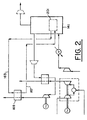
- Fig. 2 illustrates one possible use for heated process gas stream 167 from heat exchanger 165.
- pressurized air feed is treated to remove water, carbon dioxide, and other impurities in thermal swing adsorption (TSA) system 201 before the feed air is separated in the air separation process.
- TSA thermal swing adsorption
- the TSA system requires hot, dry regeneration gas to regenerate the adsorbent beds, and this is provided by heated gas stream 167.
- Cool gas is supplied to heat exchanger 165 as stream 163 from TSA system 201 or as another process stream within air separation unit 141.
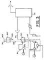
- expanded nitrogen stream 161 from expansion turbine 155 is combined with exhaust stream 115 at an intermediate point within heat exchanger 301 which heats pressurized nitrogen stream 121 upstream of expansion turbine 155. This supplements the heating of pressurized nitrogen stream 121 by recovering additional heat from expanded nitrogen stream 161.
- expanded nitrogen stream 161 is combined with exhaust stream 115 at a point within heat exchanger 301 such that the temperatures of the two streams are equal or nearly equal.
- the combined nitrogen and gas turbine exhaust stream 303 can be further cooled in heat exchanger 307 to heat process stream 305.
- Heated process stream 309 can be used elsewhere in the process, for example, for TSA regeneration within air separation unit 141 as earlier described, or can be used elsewhere outside of the process.
- expanded nitrogen stream 161 can be combined with exhaust stream 115 between heat exchangers 301 and 307. Final cooled combined nitrogen and gas turbine exhaust stream 311 is discharged to the atmosphere.
- FIG. 4 A process for power generation and air separation is illustrated in Fig. 4.
- heat energy can be recovered from gas turbine exhaust stream 115 more effectively when the mass flow rate of gas turbine exhaust stream 115 is greater than that of pressurized nitrogen stream 121.
- Reheat is used to balance the exchange of heat between these two streams wherein pressurized nitrogen stream 121 is heated in heat exchanger 401 to yield intermediate heated nitrogen stream 403, which is work expanded in expansion turbine or turbine stage 405 to yield intermediate expanded nitrogen stream 607.
- This stream is reheated in heat exchanger 401, and reheated nitrogen stream 409 is work expanded to atmospheric pressure in expansion turbine or turbine stage 411 to yield expanded nitrogen stream 413.
- Shaft work generated by turbine stages 405 and 411 may be used to drive electric generator 415 by shaft 417, or alternatively to drive other rotating machinery within the process.
- compressor 133 which provides compressed feed air to air separation unit 141, is independently driven.
- the driver (not shown) would be independent of and have no process integration with combustion engine 129 and product gas streams from air separation unit 141 which have been heated by exhaust from combustion engine 129.
- This allows air separation unit 141 to supply oxygen-enriched product gas 145 independently of any time-variant demand for electric power from generator 125.
- expansion turbines 113 and 155 preferably do not provide shaft work for feed gas compressor 133.
- decouple feed gas compressor 133 from combustion engine 129 which defines compressor 133 as an independently-driven feed gas compressor.
- compressor 133 could be driven by combustion engine 129 if desired, but in such a case the air separation unit would not necessarily operate independently and could be affected by changes in the demand for electric power from generator 125.
- Recovering work from exhaust stream 115 in the embodiments described above is accomplished in the present invention by an alternative to the usual heat recovery steam generation system and steam bottoming cycle earlier described.
- the required process equipment is significantly reduced by eliminating the heat recovery steam generator (boiler); the boiler feedwater pump and system; the steam expansion turbine; the condenser, condensate pumps, and related equipment; and the boiler feed water demineralization system.
- the heat exchanger system of the present invention is more compact than a heat recovery steam generator.
- the product gas stream from the air separation system is dry and particle-free, and this is beneficial in the operation and maintenance of the heat exchangers and expansion turbine.
- the invention efficiently utilizes pressurized product gas, a high pressure air separation unit which uses a pumped liquid or elevated pressure cycle can be utilized. These cycles generally require smaller and less expensive equipment than other cycles, and this can be a capital cost advantage.
- the air separation unit operates independently of the gas turbine combustion engine which drives the electric generator.
- the air separation unit preferably is a cryogenic separation system which separates the feed gas by cryogenic distillation.
- the feature of the invention also can be realized in principle when other types of known gas separation processes are used, for example processes which utilize adsorption, membrane permeation, or chemical separation methods.
- An elevated pressure air separation system is integrated with a gas turbine combustion engine/electric generator set using exhaust heat recovery and a nitrogen expansion turbine which also drives an electric generator.
- This system is shown in Fig. 1.
- the air separation system produces 1.814 tons (2,000 short tons) per day of oxygen product containing 95 vol% oxygen at 43,029 bar (614.7 psia).
- the electric generators produce 10,219 kW (net) of electric power.
- the system operates at a barometric pressure of 1,029 bar (14.7 psia), an ambient air temperature of 15° (59°F), relative humidity of 60%, and a cooling water temperature of 21,11°C (70°F).
- the gas turbine combustion engine is a typical industrial aeroderivative two-shaft unit with a single spool gas generator and a separate power turbine to drive the electric generator.
- a power balance for the rotating equipment is given in Table 2.
- Table 2 Power Balance for Example Equipment Item Number (Fig. 1) Shaft Power, kW Motor Terminal Input Power kW Generator Terminal Output Power kW Main Air Compressor 131 28457 28891 Oxygen Compressor 147 5807 5923 Gas Turbine Engine and Generator 129 & 125 28500 Nitrogen Expansion Turbine & Generator 155 & 157 12586 16533 NET EXPORT POWER 10219 kW NOTES: 1) Compressor seal losses have been accounted for in the balance. 2) Air separation unit losses have been accounted for in the balance. 3) Power for utilities such as coolant circulation pumps, cooling tower fans, lubrication system auxiliaries are not included.
- the process of the present invention offers an alternative method for recovering heat from the exhaust gas of a combustion engine integrated with an air separation unit in which the combustion engine drives an electric generator and a gas stream from the air separation unit is heated against the combustion engine exhaust and work expanded to produce additional electric power or drive process equipment.
- the invention offers an alternative to the well-known method of recovering heat from the combustion engine exhaust by a heat recovery steam generator system, and is useful for process situations in which such a system not appropriate or cost effective.
Landscapes
- Engineering & Computer Science (AREA)
- Mechanical Engineering (AREA)
- General Engineering & Computer Science (AREA)
- Physics & Mathematics (AREA)
- Thermal Sciences (AREA)
- Chemical & Material Sciences (AREA)
- Combustion & Propulsion (AREA)
- Separation By Low-Temperature Treatments (AREA)
- Engine Equipment That Uses Special Cycles (AREA)
- Output Control And Ontrol Of Special Type Engine (AREA)
Claims (15)
- Verfahren zur Erzeugung von elektrischer Energie und zur Zerlegung eines Speisegasgemisches (131), das Sauerstoff und Stickstoff enthält und das umfasst:(a) Verbrennen eines Oxidationsmittelgases und eines Brennstoffs (109) in einer Verbrennungskraftmaschine (129), um Wellenarbeit und warmes Abgas (115) zu erzeugen;(b) Nutzen der Wellenarbeit nach (a), um einen elektrischen Generator (125) anzutreiben, um elektrische Energie zur Verfügung zu stellen;(c) Komprimieren des Speisegasgemisches (131) und Zerlegen des daraus resultierenden komprimierten Speisegasgemisches (131) in zwei oder mehr Produktgasströme (143, 145) mit verschiedenen Zusammensetzungen, und(d) Erwärmen von wenigstens einem der Produktgasströme (143) durch indirekten Wärmeaustausch mit wenigstens einem Teil des warmen Abgases (115) von der Verbrennungskraftmaschine (129) nach (a) und Arbeitsexpandieren des daraus resultierenden erwärmten Produktgasstroms (153), um Wellenarbeit zu erzeugen und einen expandierten Produktgasstrom (161) zu ergeben, wobei das Speisegasgemisch Luft (131), einer der Produktgasströme ein mit Sauerstoff angereicherter Produktgasstrom (145) und ein weiterer der Produktgasströme ein mit Stickstoff angereicherter Produktgasstrom (143) ist, wobei der mit Stickstoff angereicherte Produktgasstrom (143) durch indirekten Wärmeaustausch mit dem warmen Abgas (115) von der Verbrennungskraftmaschine (129) in einem Wärmetauscher erwärmt wird,
dadurch gekennzeichnet, dass
das Erwärmen durch Kombinieren des expandierten, mit Stickstoff angereicherten Produktgasstroms mit dem warmen Abgas (115) an einem Zwischenpunkt im Wärmetauscher ergänzt wird. - Verfahren nach Anspruch 1, wobei die Verbrennungskraftmaschine (129) eine Gasturbinen-Verbrennungskraftmaschine ist.
- Verfahren nach Anspruch 1, wobei die Verbrennungskraftmaschine (129) ein Verbrennungsmotor ist.
- Anspruch nach Verfahren 1, wobei die Wellenarbeit, die durch Arbeitsexpandieren des sich ergebenden erwärmten Produktgasstroms (153) gewonnen wird, genutzt wird, um zusätzliche elektrische Energie zu erzeugen.
- Verfahren nach Anspruch 1, wobei die Luft durch Komprimieren und Kühlen der Luft, so dass sich ein unter Druck stehender Luft-Speisestrom ergibt, Reinigen des unter Druck stehenden Luft-Speisestroms durch Entfernen von Wasser und Kohlendioxid von dort, weiteres Kühlen des daraus resultierenden gereinigten Luft-Speisestroms und Zerlegen des daraus resultierenden gekühlten, gereinigten Luft-Speisestroms durch kryogene bzw. Tieftemperatur-Destillation zerlegt wird, um den mit Sauerstoff angereicherten Produktgasstrom (145) und den mit Stickstoff angereicherten Produktgasstrom (143) zu ergeben.
- Verfahren nach Anspruch 1, wobei der mit Stickstoff angereicherte Produktgasstrom (143) durch indirekten Wärmeaustausch mit dem warmen Abgas (115) von der Verbrennungskraftmaschine (129) erwärmt wird und der daraus resultierende erwärmte, mit Stickstoff angereicherte Produktgasstrom arbeitsexpandiert wird, um Wellenarbeit zu erzeugen und einen expandierten, mit Stickstoff angereicherten Produktgasstrom zu ergeben.
- Verfahren nach Anspruch 6, wobei wenigstens ein Teil der durch Arbeitsexpandieren des sich ergebenden erwärmten, mit Stickstoff angereicherten Produktgasstroms gewonnenen Wellenarbeit genutzt wird, um den mit Sauerstoff angereicherten Produktgasstrom zu komprimieren.
- Verfahren nach Anspruch 6, wobei der expandierte, mit Stickstoff angereicherte Produktgasstrom durch indirekten Wärmeaustausch mit einem Verfahrensgasstrom gekühlt wird, um einen erwärmten Verfahrensgasstrom zu ergeben.
- Verfahren nach Anspruch 8, wobei die Luft durch Komprimieren und Kühlen von Luft, um einen unter Druck stehenden Luft-Speisestrom zu ergeben, Reinigen des unter Druck stehenden Luft-Speisestroms durch ein zyklisches Temperaturwechseladsorptionsverfahren, um Wasser und Kohlendioxid von dort zu entfernen, weiteres Kühlen des daraus resultierenden gereinigten Luft-Speisestroms und Zerlegen des daraus resultierenden gekühlten, gereinigten Luft-Speisestroms durch kryogene bzw. Tieftemperatur-Destillation zerlegt wird, um den mit Sauerstoff angereicherten Produktgasstrom (145) und den mit Stickstoff angereicherten Produktgasstrom (143) zu ergeben, wobei der erwärmte Verfahrensgasstrom als ein Regeneriergas beim zyklischen Temperaturwechseladsorptionsverfahren verwendet wird.
- Verfahren nach Anspruch 1, wobei ein kombinierter Strom aus expandiertem, mit Stickstoff angereichertem Produktgas und gekühltem Abgas (123) vom Wärmetauscher (119) abgezogen und durch indirekten Wärmeaustausch mit einem Verfahrensgas weiter gekühlt wird, um einen erwärmten Verfahrensgasstrom zu ergeben.
- Verfahren nach Anspruch 1, das weiterhin umfasst:(e) Wiedererwärmen des expandierten Produktgasstroms nach (d) durch indirekten Wärmeaustausch mit dem warmen Abgas (115) von der Verbrennungskraftmaschine und Arbeitsexpandieren des daraus resultierenden wieder erwärmten Gases, um Wellenarbeit und ein endgültiges Produktgas mit verringertem Druck zu ergeben.
- Verfahren nach Anspruch 11, wobei die kombinierte Wellenarbeit nach (d) und (e) genutzt wird, um zusätzliche elektrische Energie zu erzeugen.
- Verfahren nach Anspruch 1, wobei das Kombinieren des Speisegasgemisches (131) nach (c) durch einen unabhängig angetriebenen Speisegas-Kompressor (133) bewirkt wird.
- Verfahren nach Anspruch 1, wobei das Speisegasgemisch Luft und einer der Produktgasströme ein mit Argon angereicherter Strom sind.
- Verfahren nach Anspruch 1, wobei der mit Stickstoff angereicherte Produktgasstrom (143) durch indirekten Wärmeaustausch mit dem warmen Abgas (115) von der Verbrennungskraftmaschine (129) in einem Wärmetauscher (119) erwärmt wird, wobei das daraus resultierende gekühlte Abgas (123) mit dem expandierten, mit Stickstoff angereicherten Produktgasstrom kombiniert wird und der daraus resultierende kombinierte Gasstrom durch indirekten Wärmeaustausch mit einem Verfahrensgas weiter gekühlt wird, um einen erwärmten Verfahrensgasstrom zu ergeben.
Applications Claiming Priority (2)
| Application Number | Priority Date | Filing Date | Title |
|---|---|---|---|
| US326153 | 1981-11-30 | ||
| US09/326,153 US6256994B1 (en) | 1999-06-04 | 1999-06-04 | Operation of an air separation process with a combustion engine for the production of atmospheric gas products and electric power |
Publications (2)
| Publication Number | Publication Date |
|---|---|
| EP1058074A1 EP1058074A1 (de) | 2000-12-06 |
| EP1058074B1 true EP1058074B1 (de) | 2007-09-12 |
Family
ID=23271025
Family Applications (1)
| Application Number | Title | Priority Date | Filing Date |
|---|---|---|---|
| EP00110996A Expired - Lifetime EP1058074B1 (de) | 1999-06-04 | 2000-05-30 | Verfahren zur Luftzerleggung mit einer Brennkraftmachine zur Herstellung von Luftgasen und elektrischer Energie |
Country Status (6)
| Country | Link |
|---|---|
| US (1) | US6256994B1 (de) |
| EP (1) | EP1058074B1 (de) |
| AT (1) | ATE373217T1 (de) |
| DE (1) | DE60036327T2 (de) |
| ES (1) | ES2292389T3 (de) |
| ZA (1) | ZA200202747B (de) |
Families Citing this family (95)
| Publication number | Priority date | Publication date | Assignee | Title |
|---|---|---|---|---|
| PL342448A1 (en) * | 1998-12-21 | 2001-06-04 | Koninkl Philips Electronics Nv | Apparatus for encoding n-bit source words into corresponding m-bit channel words and decoding m-bit channel words into corresponding n-bit source ones |
| US6745573B2 (en) | 2001-03-23 | 2004-06-08 | American Air Liquide, Inc. | Integrated air separation and power generation process |
| US6619041B2 (en) | 2001-06-29 | 2003-09-16 | L'air Liquide - Societe Anonyme A Directoire Et Conseil De Surveillance Pour L'etude Et L'exploitation Des Procedes Georges Claude | Steam generation apparatus and methods |
| US6568185B1 (en) | 2001-12-03 | 2003-05-27 | L'air Liquide Societe Anonyme A'directoire Et Conseil De Surveillance Pour L'etude Et L'exploitation Des Procedes Georges Claude | Combination air separation and steam-generation processes and plants therefore |
| US6871502B2 (en) * | 2002-02-15 | 2005-03-29 | America Air Liquide, Inc. | Optimized power generation system comprising an oxygen-fired combustor integrated with an air separation unit |
| US6694776B1 (en) * | 2003-05-14 | 2004-02-24 | Praxair Technology, Inc. | Cryogenic air separation system for producing oxygen |
| US20050121532A1 (en) * | 2003-12-05 | 2005-06-09 | Reale Michael J. | System and method for district heating with intercooled gas turbine engine |
| CN100357685C (zh) * | 2004-10-28 | 2007-12-26 | 苏州市兴鲁空分设备科技发展有限公司 | 一种空气分离的方法和装置 |
| CN100357684C (zh) * | 2004-10-28 | 2007-12-26 | 苏州市兴鲁空分设备科技发展有限公司 | 一种空气分离的方法和装置 |
| US20060149423A1 (en) * | 2004-11-10 | 2006-07-06 | Barnicki Scott D | Method for satisfying variable power demand |
| CA2616262C (en) * | 2005-07-19 | 2013-07-02 | Pacific Consolidated Industries, Llc | Mobile nitrogen generation device |
| CN100400995C (zh) * | 2006-11-22 | 2008-07-09 | 苏州市兴鲁空分设备科技发展有限公司 | 空气分离的方法和装置 |
| US8963347B2 (en) * | 2007-12-06 | 2015-02-24 | Sustainable Energy Solutions, Llc | Methods and systems for generating power from a turbine using pressurized nitrogen |
| US8673034B2 (en) * | 2008-02-21 | 2014-03-18 | General Electric Company | Methods and systems for integrated boiler feed water heating |
| MY156350A (en) | 2008-03-28 | 2016-02-15 | Exxonmobil Upstream Res Co | Low emission power generation and hydrocarbon recovery systems and methods |
| CN101981162B (zh) | 2008-03-28 | 2014-07-02 | 埃克森美孚上游研究公司 | 低排放发电和烃采收系统及方法 |
| DE102008039449A1 (de) * | 2008-08-25 | 2010-03-04 | Rheinisch-Westfälische Technische Hochschule Aachen | Emissionsfreies Karftwerk |
| US20100083940A1 (en) * | 2008-10-04 | 2010-04-08 | Woodford Leon Vrazel | Cryogenic air cooler for improving power and fuel efficiency of a motor vehicle internal combustion engine |
| CA2737133C (en) | 2008-10-14 | 2017-01-31 | Exxonmobil Upstream Research Company | Methods and systems for controlling the products of combustion |
| US9353940B2 (en) | 2009-06-05 | 2016-05-31 | Exxonmobil Upstream Research Company | Combustor systems and combustion burners for combusting a fuel |
| SG10201407421UA (en) | 2009-11-12 | 2014-12-30 | Exxonmobil Upstream Res Co | Low emission power generation and hydrocarbon recovery systems and methods |
| MY160832A (en) | 2010-07-02 | 2017-03-31 | Exxonmobil Upstream Res Co | Stoichiometric combustion with exhaust gas recirculation and direct contact cooler |
| SG186084A1 (en) | 2010-07-02 | 2013-01-30 | Exxonmobil Upstream Res Co | Low emission triple-cycle power generation systems and methods |
| CN105863844B (zh) | 2010-07-02 | 2017-11-14 | 埃克森美孚上游研究公司 | 低排放动力产生系统和方法 |
| CA2801494C (en) | 2010-07-02 | 2018-04-17 | Exxonmobil Upstream Research Company | Stoichiometric combustion of enriched air with exhaust gas recirculation |
| MY156099A (en) | 2010-07-02 | 2016-01-15 | Exxonmobil Upstream Res Co | Systems and methods for controlling combustion of a fuel |
| WO2012018458A1 (en) | 2010-08-06 | 2012-02-09 | Exxonmobil Upstream Research Company | System and method for exhaust gas extraction |
| JP6193759B2 (ja) | 2010-08-06 | 2017-09-06 | エクソンモービル アップストリーム リサーチ カンパニー | 化学量論的燃焼の最適化システム及び方法 |
| US9546814B2 (en) | 2011-03-16 | 2017-01-17 | 8 Rivers Capital, Llc | Cryogenic air separation method and system |
| TWI593872B (zh) | 2011-03-22 | 2017-08-01 | 艾克頌美孚上游研究公司 | 整合系統及產生動力之方法 |
| TWI563165B (en) | 2011-03-22 | 2016-12-21 | Exxonmobil Upstream Res Co | Power generation system and method for generating power |
| TWI564474B (zh) | 2011-03-22 | 2017-01-01 | 艾克頌美孚上游研究公司 | 於渦輪系統中控制化學計量燃燒的整合系統和使用彼之產生動力的方法 |
| TWI563166B (en) | 2011-03-22 | 2016-12-21 | Exxonmobil Upstream Res Co | Integrated generation systems and methods for generating power |
| EP2740322B1 (de) | 2011-08-04 | 2018-05-02 | Stephen Lee Cunningham | Plasma-lichtbogenbrenner und anwendungen |
| WO2013095829A2 (en) | 2011-12-20 | 2013-06-27 | Exxonmobil Upstream Research Company | Enhanced coal-bed methane production |
| US9353682B2 (en) | 2012-04-12 | 2016-05-31 | General Electric Company | Methods, systems and apparatus relating to combustion turbine power plants with exhaust gas recirculation |
| US10273880B2 (en) | 2012-04-26 | 2019-04-30 | General Electric Company | System and method of recirculating exhaust gas for use in a plurality of flow paths in a gas turbine engine |
| US9784185B2 (en) | 2012-04-26 | 2017-10-10 | General Electric Company | System and method for cooling a gas turbine with an exhaust gas provided by the gas turbine |
| US9222480B2 (en) * | 2012-08-24 | 2015-12-29 | Saudi Arabian Oil Company | Integrated method of driving a CO2 compressor of a CO2-capture system using waste heat from an internal combustion engine on board a mobile source |
| CA2890484C (en) | 2012-08-30 | 2022-07-05 | Enhanced Energy Group LLC | Cycle turbine engine power system |
| EP2890886B1 (de) * | 2012-08-30 | 2020-04-08 | Enhanced Energy Group LLC | Hubkolben-brennkraftmaschinensystem |
| US9708977B2 (en) | 2012-12-28 | 2017-07-18 | General Electric Company | System and method for reheat in gas turbine with exhaust gas recirculation |
| US9803865B2 (en) | 2012-12-28 | 2017-10-31 | General Electric Company | System and method for a turbine combustor |
| US9574496B2 (en) | 2012-12-28 | 2017-02-21 | General Electric Company | System and method for a turbine combustor |
| US10215412B2 (en) | 2012-11-02 | 2019-02-26 | General Electric Company | System and method for load control with diffusion combustion in a stoichiometric exhaust gas recirculation gas turbine system |
| US9631815B2 (en) | 2012-12-28 | 2017-04-25 | General Electric Company | System and method for a turbine combustor |
| US10161312B2 (en) | 2012-11-02 | 2018-12-25 | General Electric Company | System and method for diffusion combustion with fuel-diluent mixing in a stoichiometric exhaust gas recirculation gas turbine system |
| US9869279B2 (en) | 2012-11-02 | 2018-01-16 | General Electric Company | System and method for a multi-wall turbine combustor |
| US9611756B2 (en) | 2012-11-02 | 2017-04-04 | General Electric Company | System and method for protecting components in a gas turbine engine with exhaust gas recirculation |
| US10107495B2 (en) | 2012-11-02 | 2018-10-23 | General Electric Company | Gas turbine combustor control system for stoichiometric combustion in the presence of a diluent |
| US9599070B2 (en) | 2012-11-02 | 2017-03-21 | General Electric Company | System and method for oxidant compression in a stoichiometric exhaust gas recirculation gas turbine system |
| US10208677B2 (en) | 2012-12-31 | 2019-02-19 | General Electric Company | Gas turbine load control system |
| US9581081B2 (en) | 2013-01-13 | 2017-02-28 | General Electric Company | System and method for protecting components in a gas turbine engine with exhaust gas recirculation |
| US9512759B2 (en) | 2013-02-06 | 2016-12-06 | General Electric Company | System and method for catalyst heat utilization for gas turbine with exhaust gas recirculation |
| TW201502356A (zh) | 2013-02-21 | 2015-01-16 | Exxonmobil Upstream Res Co | 氣渦輪機排氣中氧之減少 |
| US9938861B2 (en) | 2013-02-21 | 2018-04-10 | Exxonmobil Upstream Research Company | Fuel combusting method |
| US10221762B2 (en) | 2013-02-28 | 2019-03-05 | General Electric Company | System and method for a turbine combustor |
| TW201500635A (zh) | 2013-03-08 | 2015-01-01 | Exxonmobil Upstream Res Co | 處理廢氣以供用於提高油回收 |
| US9784182B2 (en) | 2013-03-08 | 2017-10-10 | Exxonmobil Upstream Research Company | Power generation and methane recovery from methane hydrates |
| US9618261B2 (en) | 2013-03-08 | 2017-04-11 | Exxonmobil Upstream Research Company | Power generation and LNG production |
| US20140250945A1 (en) | 2013-03-08 | 2014-09-11 | Richard A. Huntington | Carbon Dioxide Recovery |
| US9617914B2 (en) | 2013-06-28 | 2017-04-11 | General Electric Company | Systems and methods for monitoring gas turbine systems having exhaust gas recirculation |
| US9835089B2 (en) | 2013-06-28 | 2017-12-05 | General Electric Company | System and method for a fuel nozzle |
| US9631542B2 (en) | 2013-06-28 | 2017-04-25 | General Electric Company | System and method for exhausting combustion gases from gas turbine engines |
| TWI654368B (zh) | 2013-06-28 | 2019-03-21 | 美商艾克頌美孚上游研究公司 | 用於控制在廢氣再循環氣渦輪機系統中的廢氣流之系統、方法與媒體 |
| US9587510B2 (en) | 2013-07-30 | 2017-03-07 | General Electric Company | System and method for a gas turbine engine sensor |
| US9903588B2 (en) | 2013-07-30 | 2018-02-27 | General Electric Company | System and method for barrier in passage of combustor of gas turbine engine with exhaust gas recirculation |
| US9951658B2 (en) | 2013-07-31 | 2018-04-24 | General Electric Company | System and method for an oxidant heating system |
| US9752458B2 (en) | 2013-12-04 | 2017-09-05 | General Electric Company | System and method for a gas turbine engine |
| US10030588B2 (en) | 2013-12-04 | 2018-07-24 | General Electric Company | Gas turbine combustor diagnostic system and method |
| US10227920B2 (en) | 2014-01-15 | 2019-03-12 | General Electric Company | Gas turbine oxidant separation system |
| US9863267B2 (en) | 2014-01-21 | 2018-01-09 | General Electric Company | System and method of control for a gas turbine engine |
| US9915200B2 (en) | 2014-01-21 | 2018-03-13 | General Electric Company | System and method for controlling the combustion process in a gas turbine operating with exhaust gas recirculation |
| US10079564B2 (en) | 2014-01-27 | 2018-09-18 | General Electric Company | System and method for a stoichiometric exhaust gas recirculation gas turbine system |
| EP3140601A4 (de) | 2014-05-09 | 2017-11-08 | Stephen Lee Cunningham | Lichtbogenofenschmelzsystem und verfahren |
| US10047633B2 (en) | 2014-05-16 | 2018-08-14 | General Electric Company | Bearing housing |
| US10655542B2 (en) | 2014-06-30 | 2020-05-19 | General Electric Company | Method and system for startup of gas turbine system drive trains with exhaust gas recirculation |
| US10060359B2 (en) | 2014-06-30 | 2018-08-28 | General Electric Company | Method and system for combustion control for gas turbine system with exhaust gas recirculation |
| US9885290B2 (en) | 2014-06-30 | 2018-02-06 | General Electric Company | Erosion suppression system and method in an exhaust gas recirculation gas turbine system |
| CN104213984A (zh) * | 2014-08-22 | 2014-12-17 | 中国华能集团清洁能源技术研究院有限公司 | 利用污氮气降低igcc循环冷却水温度的方法及装置 |
| US9869247B2 (en) | 2014-12-31 | 2018-01-16 | General Electric Company | Systems and methods of estimating a combustion equivalence ratio in a gas turbine with exhaust gas recirculation |
| US9819292B2 (en) | 2014-12-31 | 2017-11-14 | General Electric Company | Systems and methods to respond to grid overfrequency events for a stoichiometric exhaust recirculation gas turbine |
| US10788212B2 (en) | 2015-01-12 | 2020-09-29 | General Electric Company | System and method for an oxidant passageway in a gas turbine system with exhaust gas recirculation |
| US10316746B2 (en) | 2015-02-04 | 2019-06-11 | General Electric Company | Turbine system with exhaust gas recirculation, separation and extraction |
| US10253690B2 (en) | 2015-02-04 | 2019-04-09 | General Electric Company | Turbine system with exhaust gas recirculation, separation and extraction |
| US10094566B2 (en) | 2015-02-04 | 2018-10-09 | General Electric Company | Systems and methods for high volumetric oxidant flow in gas turbine engine with exhaust gas recirculation |
| US10267270B2 (en) | 2015-02-06 | 2019-04-23 | General Electric Company | Systems and methods for carbon black production with a gas turbine engine having exhaust gas recirculation |
| US10145269B2 (en) | 2015-03-04 | 2018-12-04 | General Electric Company | System and method for cooling discharge flow |
| US10480792B2 (en) | 2015-03-06 | 2019-11-19 | General Electric Company | Fuel staging in a gas turbine engine |
| DE102015207791B4 (de) * | 2015-04-28 | 2018-11-15 | Ford Global Technologies, Llc | Kraftfahrzeug |
| WO2018042336A2 (en) | 2016-08-30 | 2018-03-08 | 8 Rivers Capital, Llc | Cryogenic air separation method for producing oxygen at high pressures |
| WO2018106528A1 (en) * | 2016-12-08 | 2018-06-14 | Atlas Copco Comptec, Llc | Waste heat recovery system |
| US11931685B2 (en) | 2020-09-10 | 2024-03-19 | Enhanced Energy Group LLC | Carbon capture systems |
| WO2024040002A1 (en) * | 2022-08-19 | 2024-02-22 | Enhanced Energy Group LLC | System and method of co2 thermal swing adsorption with wet regeneration and hot drying |
| WO2024040000A1 (en) * | 2022-08-19 | 2024-02-22 | Enhanced Energy Group LLC | System of co2 thermal swing adsorption with wet regeneration and hot drying |
Family Cites Families (35)
| Publication number | Priority date | Publication date | Assignee | Title |
|---|---|---|---|---|
| US3731495A (en) | 1970-12-28 | 1973-05-08 | Union Carbide Corp | Process of and apparatus for air separation with nitrogen quenched power turbine |
| IL36741A (en) | 1971-04-30 | 1974-11-29 | Zakon T | Method for the separation of gaseous mixtures with recuperation of mechanical energy and apparatus for carrying out this method |
| US3868817A (en) * | 1973-12-27 | 1975-03-04 | Texaco Inc | Gas turbine process utilizing purified fuel gas |
| IL44298A (en) | 1974-02-27 | 1978-10-31 | Tsadok Zakon | Method for the separation of air with recuperation of mechanical energy |
| DE2503193A1 (de) | 1975-01-27 | 1976-07-29 | Linde Ag | Verfahren zur herstellung eines heizgases durch druckvergasung kohlenstoffhaltiger brennstoffe |
| DE2835852C2 (de) | 1978-08-16 | 1982-11-25 | Kraftwerk Union AG, 4330 Mülheim | Kombinierte Gas-Dampfkraftanlage mit einer Vergasungseinrichtung für den Brennstoff |
| US4224045A (en) | 1978-08-23 | 1980-09-23 | Union Carbide Corporation | Cryogenic system for producing low-purity oxygen |
| US4275562A (en) * | 1979-08-06 | 1981-06-30 | Institute Of Gas Technology | Composite energy producing gas turbine |
| DE3408937A1 (de) | 1984-01-31 | 1985-08-08 | BBC Aktiengesellschaft Brown, Boveri & Cie., Baden, Aargau | Kombinierte gas-/dampf-kraftwerkanlage |
| DE3415224A1 (de) | 1984-04-21 | 1985-10-24 | Kraftwerk Union AG, 4330 Mülheim | Gasturbinen- und dampfkraftwerk mit einer integrierten kohlevergasungsanlage |
| ATE34201T1 (de) | 1985-08-05 | 1988-05-15 | Siemens Ag | Kombiniertes gas- und dampfturbinenkraftwerk. |
| US4707994A (en) | 1986-03-10 | 1987-11-24 | Air Products And Chemicals, Inc. | Gas separation process with single distillation column |
| US4785621A (en) | 1987-05-28 | 1988-11-22 | General Electric Company | Air bottoming cycle for coal gasification plant |
| GB8820582D0 (en) | 1988-08-31 | 1988-09-28 | Boc Group Plc | Air separation |
| GB8824216D0 (en) | 1988-10-15 | 1988-11-23 | Boc Group Plc | Air separation |
| GB8913001D0 (en) | 1989-06-06 | 1989-07-26 | Boc Group Plc | Air separation |
| US5081845A (en) | 1990-07-02 | 1992-01-21 | Air Products And Chemicals, Inc. | Integrated air separation plant - integrated gasification combined cycle power generator |
| GB9105109D0 (en) | 1991-03-11 | 1991-04-24 | Boc Group Plc | Air separation |
| GB9111157D0 (en) | 1991-05-23 | 1991-07-17 | Boc Group Plc | Fluid production method and apparatus |
| US5257504A (en) | 1992-02-18 | 1993-11-02 | Air Products And Chemicals, Inc. | Multiple reboiler, double column, elevated pressure air separation cycles and their integration with gas turbines |
| US5421166A (en) | 1992-02-18 | 1995-06-06 | Air Products And Chemicals, Inc. | Integrated air separation plant-integrated gasification combined cycle power generator |
| GB9208647D0 (en) | 1992-04-22 | 1992-06-10 | Boc Group Plc | Air separation |
| US5251451A (en) | 1992-08-28 | 1993-10-12 | Air Products And Chemicals, Inc. | Multiple reboiler, double column, air boosted, elevated pressure air separation cycle and its integration with gas turbines |
| US5251450A (en) | 1992-08-28 | 1993-10-12 | Air Products And Chemicals, Inc. | Efficient single column air separation cycle and its integration with gas turbines |
| DE4301100C2 (de) | 1993-01-18 | 2002-06-20 | Alstom Schweiz Ag Baden | Verfahren zum Betrieb eines Kombikraftwerkes mit Kohle- oder Oelvergasung |
| US5388395A (en) | 1993-04-27 | 1995-02-14 | Air Products And Chemicals, Inc. | Use of nitrogen from an air separation unit as gas turbine air compressor feed refrigerant to improve power output |
| US5459994A (en) | 1993-05-28 | 1995-10-24 | Praxair Technology, Inc. | Gas turbine-air separation plant combination |
| US5406786A (en) | 1993-07-16 | 1995-04-18 | Air Products And Chemicals, Inc. | Integrated air separation - gas turbine electrical generation process |
| US5687570A (en) * | 1994-02-28 | 1997-11-18 | Ormat Industries Ltd. | Externally fired combined cycle gas turbine system |
| DE19529681C2 (de) | 1995-08-11 | 1997-05-28 | Linde Ag | Verfahren und Vorrichtung zur Luftzerlegung durch Tieftemperaturrektifikation |
| US5740673A (en) | 1995-11-07 | 1998-04-21 | Air Products And Chemicals, Inc. | Operation of integrated gasification combined cycle power generation systems at part load |
| US5666823A (en) | 1996-01-31 | 1997-09-16 | Air Products And Chemicals, Inc. | High pressure combustion turbine and air separation system integration |
| US5722259A (en) | 1996-03-13 | 1998-03-03 | Air Products And Chemicals, Inc. | Combustion turbine and elevated pressure air separation system with argon recovery |
| GB9624819D0 (en) | 1996-11-28 | 1997-01-15 | Air Prod & Chem | Use of elevated pressure nitrogen streams to perform work |
| US5979183A (en) * | 1998-05-22 | 1999-11-09 | Air Products And Chemicals, Inc. | High availability gas turbine drive for an air separation unit |
-
1999
- 1999-06-04 US US09/326,153 patent/US6256994B1/en not_active Expired - Fee Related
-
2000
- 2000-05-30 ES ES00110996T patent/ES2292389T3/es not_active Expired - Lifetime
- 2000-05-30 DE DE60036327T patent/DE60036327T2/de not_active Expired - Fee Related
- 2000-05-30 AT AT00110996T patent/ATE373217T1/de not_active IP Right Cessation
- 2000-05-30 EP EP00110996A patent/EP1058074B1/de not_active Expired - Lifetime
- 2000-06-01 ZA ZA200202747A patent/ZA200202747B/xx unknown
Also Published As
| Publication number | Publication date |
|---|---|
| ZA200202747B (en) | 2001-12-03 |
| DE60036327T2 (de) | 2007-12-27 |
| ATE373217T1 (de) | 2007-09-15 |
| EP1058074A1 (de) | 2000-12-06 |
| DE60036327D1 (de) | 2007-10-25 |
| ES2292389T3 (es) | 2008-03-16 |
| US6256994B1 (en) | 2001-07-10 |
Similar Documents
| Publication | Publication Date | Title |
|---|---|---|
| EP1058074B1 (de) | Verfahren zur Luftzerleggung mit einer Brennkraftmachine zur Herstellung von Luftgasen und elektrischer Energie | |
| EP1058073B1 (de) | Luftzerleggungsverfahren mit einer Gasturbine | |
| US6345493B1 (en) | Air separation process and system with gas turbine drivers | |
| JP3161696B2 (ja) | 燃焼タービンを統合した空気分離方法 | |
| US10746461B2 (en) | Cryogenic air separation method for producing oxygen at high pressures | |
| US6871502B2 (en) | Optimized power generation system comprising an oxygen-fired combustor integrated with an air separation unit | |
| EP0465193B1 (de) | Kombinierter Kraftwerkkreislauf mit integrierter Luftzerlegung und Brennstoffvergasung | |
| US6141950A (en) | Integrated air separation and combustion turbine process with steam generation by indirect heat exchange with nitrogen | |
| US5040370A (en) | Integrated air separation/metallurgical process | |
| EP0503900B1 (de) | Lufttrennung | |
| EP0150990B1 (de) | Verfahren zur Leistungsproduktion | |
| US20040134197A1 (en) | Hybrid oxygen-fired power generation system | |
| US8065879B2 (en) | Thermal integration of oxygen plants | |
| US7258849B2 (en) | Method for the production of nitric acid | |
| US6718794B2 (en) | Method and apparatus for generating energy | |
| EP2741036A1 (de) | Verfahren und Vorrichtung zur Abscheidung von Luft durch kryogene Destillation | |
| US6058736A (en) | Air separation plant | |
| US6161375A (en) | Air separation and combined cycle power plant | |
| US6050105A (en) | Apparatus and method for compressing a nitrogen product | |
| Smith et al. | Air separation unit integration for alternative fuel projects | |
| GB2328273A (en) | Gas separation | |
| GB2328272A (en) | Air Separation | |
| GB2328271A (en) | Air Separation |
Legal Events
| Date | Code | Title | Description |
|---|---|---|---|
| PUAI | Public reference made under article 153(3) epc to a published international application that has entered the european phase |
Free format text: ORIGINAL CODE: 0009012 |
|
| AK | Designated contracting states |
Kind code of ref document: A1 Designated state(s): AT BE CH CY DE DK ES FI FR GB GR IE IT LI LU MC NL PT SE |
|
| AX | Request for extension of the european patent |
Free format text: AL;LT;LV;MK;RO;SI |
|
| 17P | Request for examination filed |
Effective date: 20010125 |
|
| AKX | Designation fees paid |
Free format text: AT BE CH CY DE DK ES FI FR GB GR IE IT LI LU MC NL PT SE |
|
| 17Q | First examination report despatched |
Effective date: 20011031 |
|
| GRAP | Despatch of communication of intention to grant a patent |
Free format text: ORIGINAL CODE: EPIDOSNIGR1 |
|
| GRAS | Grant fee paid |
Free format text: ORIGINAL CODE: EPIDOSNIGR3 |
|
| GRAA | (expected) grant |
Free format text: ORIGINAL CODE: 0009210 |
|
| AK | Designated contracting states |
Kind code of ref document: B1 Designated state(s): AT BE CH CY DE DK ES FI FR GB GR IE IT LI LU MC NL PT SE |
|
| REG | Reference to a national code |
Ref country code: GB Ref legal event code: FG4D |
|
| REG | Reference to a national code |
Ref country code: CH Ref legal event code: EP |
|
| REF | Corresponds to: |
Ref document number: 60036327 Country of ref document: DE Date of ref document: 20071025 Kind code of ref document: P |
|
| REG | Reference to a national code |
Ref country code: IE Ref legal event code: FG4D |
|
| PG25 | Lapsed in a contracting state [announced via postgrant information from national office to epo] |
Ref country code: FI Free format text: LAPSE BECAUSE OF FAILURE TO SUBMIT A TRANSLATION OF THE DESCRIPTION OR TO PAY THE FEE WITHIN THE PRESCRIBED TIME-LIMIT Effective date: 20070912 |
|
| PG25 | Lapsed in a contracting state [announced via postgrant information from national office to epo] |
Ref country code: AT Free format text: LAPSE BECAUSE OF FAILURE TO SUBMIT A TRANSLATION OF THE DESCRIPTION OR TO PAY THE FEE WITHIN THE PRESCRIBED TIME-LIMIT Effective date: 20070912 Ref country code: LI Free format text: LAPSE BECAUSE OF FAILURE TO SUBMIT A TRANSLATION OF THE DESCRIPTION OR TO PAY THE FEE WITHIN THE PRESCRIBED TIME-LIMIT Effective date: 20070912 Ref country code: CH Free format text: LAPSE BECAUSE OF FAILURE TO SUBMIT A TRANSLATION OF THE DESCRIPTION OR TO PAY THE FEE WITHIN THE PRESCRIBED TIME-LIMIT Effective date: 20070912 |
|
| REG | Reference to a national code |
Ref country code: ES Ref legal event code: FG2A Ref document number: 2292389 Country of ref document: ES Kind code of ref document: T3 |
|
| REG | Reference to a national code |
Ref country code: CH Ref legal event code: PL |
|
| ET | Fr: translation filed | ||
| PG25 | Lapsed in a contracting state [announced via postgrant information from national office to epo] |
Ref country code: GR Free format text: LAPSE BECAUSE OF FAILURE TO SUBMIT A TRANSLATION OF THE DESCRIPTION OR TO PAY THE FEE WITHIN THE PRESCRIBED TIME-LIMIT Effective date: 20071213 |
|
| PG25 | Lapsed in a contracting state [announced via postgrant information from national office to epo] |
Ref country code: PT Free format text: LAPSE BECAUSE OF FAILURE TO SUBMIT A TRANSLATION OF THE DESCRIPTION OR TO PAY THE FEE WITHIN THE PRESCRIBED TIME-LIMIT Effective date: 20080212 |
|
| PG25 | Lapsed in a contracting state [announced via postgrant information from national office to epo] |
Ref country code: SE Free format text: LAPSE BECAUSE OF FAILURE TO SUBMIT A TRANSLATION OF THE DESCRIPTION OR TO PAY THE FEE WITHIN THE PRESCRIBED TIME-LIMIT Effective date: 20071212 |
|
| PLBE | No opposition filed within time limit |
Free format text: ORIGINAL CODE: 0009261 |
|
| STAA | Information on the status of an ep patent application or granted ep patent |
Free format text: STATUS: NO OPPOSITION FILED WITHIN TIME LIMIT |
|
| PG25 | Lapsed in a contracting state [announced via postgrant information from national office to epo] |
Ref country code: DK Free format text: LAPSE BECAUSE OF FAILURE TO SUBMIT A TRANSLATION OF THE DESCRIPTION OR TO PAY THE FEE WITHIN THE PRESCRIBED TIME-LIMIT Effective date: 20070912 |
|
| PGFP | Annual fee paid to national office [announced via postgrant information from national office to epo] |
Ref country code: DE Payment date: 20080530 Year of fee payment: 9 |
|
| 26N | No opposition filed |
Effective date: 20080613 |
|
| PGFP | Annual fee paid to national office [announced via postgrant information from national office to epo] |
Ref country code: IT Payment date: 20080521 Year of fee payment: 9 |
|
| PG25 | Lapsed in a contracting state [announced via postgrant information from national office to epo] |
Ref country code: MC Free format text: LAPSE BECAUSE OF NON-PAYMENT OF DUE FEES Effective date: 20080531 |
|
| PG25 | Lapsed in a contracting state [announced via postgrant information from national office to epo] |
Ref country code: IE Free format text: LAPSE BECAUSE OF NON-PAYMENT OF DUE FEES Effective date: 20080530 |
|
| PG25 | Lapsed in a contracting state [announced via postgrant information from national office to epo] |
Ref country code: CY Free format text: LAPSE BECAUSE OF FAILURE TO SUBMIT A TRANSLATION OF THE DESCRIPTION OR TO PAY THE FEE WITHIN THE PRESCRIBED TIME-LIMIT Effective date: 20070912 |
|
| PGFP | Annual fee paid to national office [announced via postgrant information from national office to epo] |
Ref country code: ES Payment date: 20090518 Year of fee payment: 10 |
|
| PGFP | Annual fee paid to national office [announced via postgrant information from national office to epo] |
Ref country code: BE Payment date: 20090619 Year of fee payment: 10 |
|
| PG25 | Lapsed in a contracting state [announced via postgrant information from national office to epo] |
Ref country code: LU Free format text: LAPSE BECAUSE OF NON-PAYMENT OF DUE FEES Effective date: 20080530 Ref country code: DE Free format text: LAPSE BECAUSE OF NON-PAYMENT OF DUE FEES Effective date: 20091201 |
|
| PGFP | Annual fee paid to national office [announced via postgrant information from national office to epo] |
Ref country code: NL Payment date: 20100510 Year of fee payment: 11 |
|
| BERE | Be: lapsed |
Owner name: AIR PRODUCTS AND CHEMICALS, INC. Effective date: 20100531 |
|
| PG25 | Lapsed in a contracting state [announced via postgrant information from national office to epo] |
Ref country code: IT Free format text: LAPSE BECAUSE OF NON-PAYMENT OF DUE FEES Effective date: 20090530 Ref country code: BE Free format text: LAPSE BECAUSE OF NON-PAYMENT OF DUE FEES Effective date: 20100531 |
|
| REG | Reference to a national code |
Ref country code: ES Ref legal event code: FD2A Effective date: 20110714 |
|
| PG25 | Lapsed in a contracting state [announced via postgrant information from national office to epo] |
Ref country code: ES Free format text: LAPSE BECAUSE OF NON-PAYMENT OF DUE FEES Effective date: 20110704 |
|
| PG25 | Lapsed in a contracting state [announced via postgrant information from national office to epo] |
Ref country code: ES Free format text: LAPSE BECAUSE OF NON-PAYMENT OF DUE FEES Effective date: 20100531 |
|
| REG | Reference to a national code |
Ref country code: NL Ref legal event code: V1 Effective date: 20111201 |
|
| PG25 | Lapsed in a contracting state [announced via postgrant information from national office to epo] |
Ref country code: NL Free format text: LAPSE BECAUSE OF NON-PAYMENT OF DUE FEES Effective date: 20111201 |
|
| REG | Reference to a national code |
Ref country code: FR Ref legal event code: PLFP Year of fee payment: 16 |
|
| PGFP | Annual fee paid to national office [announced via postgrant information from national office to epo] |
Ref country code: GB Payment date: 20150424 Year of fee payment: 16 |
|
| PGFP | Annual fee paid to national office [announced via postgrant information from national office to epo] |
Ref country code: FR Payment date: 20150424 Year of fee payment: 16 |
|
| GBPC | Gb: european patent ceased through non-payment of renewal fee |
Effective date: 20160530 |
|
| REG | Reference to a national code |
Ref country code: FR Ref legal event code: ST Effective date: 20170131 |
|
| PG25 | Lapsed in a contracting state [announced via postgrant information from national office to epo] |
Ref country code: FR Free format text: LAPSE BECAUSE OF NON-PAYMENT OF DUE FEES Effective date: 20160531 |
|
| PG25 | Lapsed in a contracting state [announced via postgrant information from national office to epo] |
Ref country code: GB Free format text: LAPSE BECAUSE OF NON-PAYMENT OF DUE FEES Effective date: 20160530 |