EP1057996A2 - Feststofftriebwerk für eine Staustrahlrakete - Google Patents
Feststofftriebwerk für eine Staustrahlrakete Download PDFInfo
- Publication number
- EP1057996A2 EP1057996A2 EP00111216A EP00111216A EP1057996A2 EP 1057996 A2 EP1057996 A2 EP 1057996A2 EP 00111216 A EP00111216 A EP 00111216A EP 00111216 A EP00111216 A EP 00111216A EP 1057996 A2 EP1057996 A2 EP 1057996A2
- Authority
- EP
- European Patent Office
- Prior art keywords
- solid fuel
- combustion chamber
- engine according
- fuel engine
- gas
- Prior art date
- Legal status (The legal status is an assumption and is not a legal conclusion. Google has not performed a legal analysis and makes no representation as to the accuracy of the status listed.)
- Withdrawn
Links
- 239000004449 solid propellant Substances 0.000 title claims description 38
- 238000002485 combustion reaction Methods 0.000 claims abstract description 70
- 238000007789 sealing Methods 0.000 claims abstract description 9
- 239000007789 gas Substances 0.000 claims description 115
- 239000002737 fuel gas Substances 0.000 claims description 9
- 239000011226 reinforced ceramic Substances 0.000 claims description 9
- 230000002787 reinforcement Effects 0.000 claims description 8
- 229910000831 Steel Inorganic materials 0.000 claims description 6
- 239000000463 material Substances 0.000 claims description 6
- 239000010959 steel Substances 0.000 claims description 6
- 229920000049 Carbon (fiber) Polymers 0.000 claims description 4
- 239000004917 carbon fiber Substances 0.000 claims description 4
- 238000001816 cooling Methods 0.000 claims description 4
- VNWKTOKETHGBQD-UHFFFAOYSA-N methane Chemical compound C VNWKTOKETHGBQD-UHFFFAOYSA-N 0.000 claims description 4
- 238000011144 upstream manufacturing Methods 0.000 claims description 4
- ZOKXTWBITQBERF-UHFFFAOYSA-N Molybdenum Chemical compound [Mo] ZOKXTWBITQBERF-UHFFFAOYSA-N 0.000 claims description 3
- 229910052782 aluminium Inorganic materials 0.000 claims description 3
- XAGFODPZIPBFFR-UHFFFAOYSA-N aluminium Chemical compound [Al] XAGFODPZIPBFFR-UHFFFAOYSA-N 0.000 claims description 3
- 239000007788 liquid Substances 0.000 claims description 3
- 229910052751 metal Inorganic materials 0.000 claims description 3
- 239000002184 metal Substances 0.000 claims description 3
- 229910052750 molybdenum Inorganic materials 0.000 claims description 3
- 239000011733 molybdenum Substances 0.000 claims description 3
- 238000009834 vaporization Methods 0.000 claims description 3
- 230000008016 vaporization Effects 0.000 claims description 3
- XLYOFNOQVPJJNP-UHFFFAOYSA-N water Substances O XLYOFNOQVPJJNP-UHFFFAOYSA-N 0.000 claims description 3
- 239000002210 silicon-based material Substances 0.000 claims description 2
- 239000007787 solid Substances 0.000 claims description 2
- 230000000694 effects Effects 0.000 claims 1
- 238000011161 development Methods 0.000 description 4
- 230000018109 developmental process Effects 0.000 description 4
- 239000000446 fuel Substances 0.000 description 3
- OKTJSMMVPCPJKN-UHFFFAOYSA-N Carbon Chemical compound [C] OKTJSMMVPCPJKN-UHFFFAOYSA-N 0.000 description 2
- 239000003570 air Substances 0.000 description 2
- 229910052799 carbon Inorganic materials 0.000 description 2
- 235000015842 Hesperis Nutrition 0.000 description 1
- 235000012633 Iberis amara Nutrition 0.000 description 1
- RTAQQCXQSZGOHL-UHFFFAOYSA-N Titanium Chemical compound [Ti] RTAQQCXQSZGOHL-UHFFFAOYSA-N 0.000 description 1
- 230000002411 adverse Effects 0.000 description 1
- 239000012080 ambient air Substances 0.000 description 1
- 230000001419 dependent effect Effects 0.000 description 1
- 238000009413 insulation Methods 0.000 description 1
- 230000000149 penetrating effect Effects 0.000 description 1
- 229920001296 polysiloxane Polymers 0.000 description 1
- 230000001681 protective effect Effects 0.000 description 1
- 239000010936 titanium Substances 0.000 description 1
- 229910052719 titanium Inorganic materials 0.000 description 1
Images
Classifications
-
- F—MECHANICAL ENGINEERING; LIGHTING; HEATING; WEAPONS; BLASTING
- F02—COMBUSTION ENGINES; HOT-GAS OR COMBUSTION-PRODUCT ENGINE PLANTS
- F02K—JET-PROPULSION PLANTS
- F02K9/00—Rocket-engine plants, i.e. plants carrying both fuel and oxidant therefor; Control thereof
- F02K9/08—Rocket-engine plants, i.e. plants carrying both fuel and oxidant therefor; Control thereof using solid propellants
- F02K9/32—Constructional parts; Details not otherwise provided for
- F02K9/34—Casings; Combustion chambers; Liners thereof
-
- F—MECHANICAL ENGINEERING; LIGHTING; HEATING; WEAPONS; BLASTING
- F02—COMBUSTION ENGINES; HOT-GAS OR COMBUSTION-PRODUCT ENGINE PLANTS
- F02K—JET-PROPULSION PLANTS
- F02K7/00—Plants in which the working fluid is used in a jet only, i.e. the plants not having a turbine or other engine driving a compressor or a ducted fan; Control thereof
- F02K7/10—Plants in which the working fluid is used in a jet only, i.e. the plants not having a turbine or other engine driving a compressor or a ducted fan; Control thereof characterised by having ram-action compression, i.e. aero-thermo-dynamic-ducts or ram-jet engines
- F02K7/18—Composite ram-jet/rocket engines
-
- F—MECHANICAL ENGINEERING; LIGHTING; HEATING; WEAPONS; BLASTING
- F02—COMBUSTION ENGINES; HOT-GAS OR COMBUSTION-PRODUCT ENGINE PLANTS
- F02K—JET-PROPULSION PLANTS
- F02K9/00—Rocket-engine plants, i.e. plants carrying both fuel and oxidant therefor; Control thereof
- F02K9/08—Rocket-engine plants, i.e. plants carrying both fuel and oxidant therefor; Control thereof using solid propellants
- F02K9/26—Burning control
Definitions
- the invention relates to a solid fuel engine for a ramjet rocket according to the Preamble of claim 1.
- Solid-state engines for jet rockets are known, one by one tubular casing encased combustion chamber and one of the combustion chamber upstream, encased by a tubular jacket gas generator for generation a fuel gas from a solid fuel. Furthermore is between gas generators and combustion chamber a gas flow control unit for controlling the gas generator from the Combustion chamber supplied fuel gas flow arranged. For this, e.g. on DE 85 32 148 referred.
- gas generators and combustion chambers are in each case closed pressure vessels with basket-shaped arched bottoms. Between these is the Gas flow control unit arranged. If the pressure plates of Gas generator and combustion chamber under the influence of internal pressure and heat when Operation of the engine adversely affects the function of the gas flow control unit.
- the object of the invention is therefore a solid fuel engine for a ramjet rocket to specify at which reliable operation of the gas flow control unit is ensured is.
- a solid fuel engine for a ram rocket is provided a combustion chamber enveloped by a tubular jacket and one of the Combustion chamber upstream, encased by a tubular jacket gas generator to generate a fuel gas from a solid fuel and one between gas generators and combustion chamber arranged gas flow control unit for controlling that of the gas generator contains the fuel gas stream supplied to the combustion chamber.
- gas flow control unit middle section which in a load-bearing Connection with the combustion chamber jacket and the gas generator jacket is arranged and a first pressure plate closing the gas generator and one the combustion chamber final second pressure plate and a between the pressure plates
- Base structure housing the gas flow control unit and supporting the pressure floors having.
- center section one of sealing elements against the Contains gas generator and the combustion chamber closed pressure-neutral zone by which measuring and supply lines lead to the inside of the basic structure.
- the pressure-neutral zone is, for example, pot-shaped pressure plates and the shell structures of the combustion chamber and gas generator are limited and e.g. by Sealing rings sealed.
- the middle section is of one surrounded tubular tubular section.
- the jacket section preferably forms the gas generator jacket and the Part of the jacket structure connecting the combustion chamber jacket.
- the gas generator jacket, the jacket section of the middle section and the combustion chamber jacket has essentially the same diameter.
- Sheath structures of the gas generator, combustion chamber and middle section on their adjacent ends are stepped and pushed into each other and through a load-bearing connection are firmly coupled.
- the load-bearing connection between the Sheath structures preferably formed by a wedge spring system.
- the shell structures of gas generators and Combustion chamber advantageously form and are the jacket section of the middle section firmly coupled to each other by a load-bearing connection.
- the middle section between the jacket structures of gas generators is preferred and combustion chamber by means of shoulder rings which engage with one another in the axial direction positioned.
- the basic structure is Center section formed by a circular body, and the pressure plates are as cylindrical ones placed on the circular body Pot-shaped bottoms with edge reinforcements.
- the Sheath structures of the gas generator and combustion chamber are stepped into one another in a ring pushed and connected by a load-bearing connection and one form the tubular section surrounding the central section, and that to the Sheath structures of the gas generator and combustion chamber shoulder rings are provided, which support and fix the middle section in the longitudinal direction.
- the gas generator and combustion chamber provided shoulder rings against shoulders support, which are formed on the pot-shaped bottoms of the middle section.
- These heat shields are preferably made of a thermally ablative material.
- the ablative heat shields advantageously consist of a silicone-based material.
- the Basic structure consists of a material that has a low mass density and a has great specific heat.
- the base structure preferably consists of a light metal, in particular aluminum, or from high-strength, in particular carbon fiber-reinforced ceramic.
- the pressure plates are preferably made of steel or high-strength, in particular carbon fiber reinforced ceramic.
- the middle section in the longitudinal direction of the engine, in particular axially parallel gas guide tube for the passage of the gas flow to be supplied from the gas generator to the combustion chamber.
- the gas guide tube can preferably consist of molybdenum.
- the gas guide tube can advantageously be made of fiber-reinforced Ceramics exist.
- the gas conduit from a thermal shield from the interior of the center section Insulation jacket is surrounded.
- the gas flow control unit advantageously contains a flow of the gas flow by the actuator influencing the gas guide tube.
- the Gas flow control unit housed in the basic structure of the middle section Includes actuator that is coupled to the actuator, the actuator outside the base structure is arranged and provided with one at the end of the gas guide tube Control nozzle in the sense of influencing the gas flow through the gas guide tube cooperates.
- the middle section is advantageously in the form of a module as a self-contained one Functional unit trained.
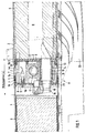
- FIG 1 is a cross-sectional view of a part of a solid fuel engine for a Ram blast rocket shown.
- the engine contains a tubular casing 2 encased combustion chamber B and one upstream of the combustion chamber B, by one tubular jacket 1 enveloped gas generator G.
- a Starting fuel S with which the combustion chamber B is initially operated as a starting engine.
- a solid fuel is present in the gas generator G, which is used to generate a Fuel gas is used, which after combustion of the starting fuel S of the combustion chamber B is supplied to there together with ambient air supplied via air inlets 23 to be burned.
- a gas flow control unit R for controlling the gas generator G of the combustion chamber B supplied fuel gas flow.
- the gas flow control unit R which is a flow connection between the gas generator G and the combustion chamber B producing gas guide tube, one on the side of the gas generator G on the gas guide tube 12 arranged control nozzle 15, one with the control nozzle 15 in the sense influencing the flow of the gas flow through the gas conduit 12 cooperating actuator 16 and one coupled to the actuator 16
- Actuator 17 comprises is housed in a middle section 4, which is between the Gas generator G and the combustion chamber B is located.
- the actuator 17 becomes dependent from externally supplied data and from one by one in the gas generator G prevailing pressure-detecting pressure sensor 18 generated signal controlled.
- the middle section 4 is in a load-bearing connection with the jacket 2 Combustion chamber B and the jacket 1 of the gas generator G arranged and includes a Gas generator G closing first pressure plate 8 and a combustion chamber B final second pressure plate 9 and one between these two pressure plates 8,9 arranged base structure 7, which houses the gas flow control unit R.
- This Base structure 7 forms a solid support for the pressure floors 8,9, which despite the during operation in the gas generator G and in the combustion chamber B, the pressures and the resulting high temperatures are not deformed and thus one ensure reliable operation of the gas flow control unit R.
- the middle section 4 is surrounded by a tubular jacket section 4a, which connects the jacket 1 of the gas generator G and the jacket 2 of the combustion chamber B.
- the Gas generator jacket 1, the jacket section 4a of the middle section 4 and Combustion chamber casing 2 have essentially the same diameter.
- the Gas generator jacket 1, the combustion chamber jacket 2 and the jacket section 4a Center section 4 are stepped at their adjoining ends and pushed into each other and coupled to each other by a load-bearing connection, which is formed by a wedge spring system 3.
- the jacket section 4a of the middle section 4 is by the jacket structures 1, 2 of gas generators pushed into one another at their ends G and combustion chamber B. Between the jacket structures 1, 2 from gas generators and Combustion chamber, middle section 4 is positioned in the axial direction by shoulder rings 5, 6, which are formed on the combustion chamber jacket 2 and the gas generator jacket 1 Interlocking shoulders.
- the base structure 7 of the middle section 4 is formed by a circular body formed and the pressure plates 8,9 are designed as cup-shaped plates, each have cylindrical edge reinforcements 21,22 and on the round-shaped Base body of the base structure 7 are placed.
- On the pot-shaped bottoms are 8.9 Shoulders 5a, 6a formed, against which the shoulder rings 5,6 from gas generator G and support combustion chamber B.
- Heat shields 10, 11 made of a thermally ablative material based on silicone are provided.
- the base structure 7 consists of a material which has a low mass density and has a large specific heat, preferably a light metal, in particular Aluminum, or from high-strength, in particular carbon fiber-reinforced ceramic, one additional active cooling is required.
- a light metal in particular Aluminum
- high-strength in particular carbon fiber-reinforced ceramic
- the pressure plates 8.9 are made of steel, titanium or high-strength, in particular carbon fiber reinforced ceramic.
- Gas flow tube 12 provided in the gas flow extends in the longitudinal direction of the engine axially parallel to the engine axis.
- the gas pipe 12 is made of molybdenum, it can alternatively, it can also be made from fiber-reinforced ceramic. So that the inside of the Center section 4 against the heat of the fuel gas flowing through the gas guide tube 12 is protected, the gas guide tube 12 is surrounded by an insulating jacket 13, which on the outer circumference of the gas conduit 12 is applied and in turn by a Steel bush 14 is included.
- control nozzle 15 provided at the gas generator end of the gas guide tube 12 cooperating actuator is located outside the base structure 7 and is connected to the within the base structure 7 accommodated actuator 17 by means of a coupled to the gas generator-side first pressure plate 8 penetrating shaft 24.
- the through the base structure 7, the two pressure plates 8.9 and the inside of the Base structure 7 arranged components such as gas flow control unit R and pressure sensor 18 formed arrangement results in a self-contained functional unit in the form of a Module, which with the combustion chamber casing 2 and the gas generator jacket 1 is assembled.
Landscapes
- Engineering & Computer Science (AREA)
- Chemical & Material Sciences (AREA)
- Combustion & Propulsion (AREA)
- Mechanical Engineering (AREA)
- General Engineering & Computer Science (AREA)
- Fluidized-Bed Combustion And Resonant Combustion (AREA)
- Air Bags (AREA)
Abstract
Description
- 1
- Gaserzeugermantel
- 2
- Brennkammermantel
- 3
- Keilfederanordnung
- 4
- Mittelsektion
- 4a
- röhrenförmiger Mantelabschnitt
- 5
- Schulterring
- 6
- Schulterring
- 7
- Basisstruktur
- 8
- Druckboden (erster)
- 9
- Druckboden (zweiter)
- 10
- Hitzeschild
- 11
- Hitzeschild
- 12
- Gasleitrohr
- 13
- Isoliermantel
- 14
- Hüllbuchse
- 15
- Regeldüse
- 16
- Stellglied
- 17
- Stellantrieb
- 18
- Drucksensor
- 19
- Dichtungsring
- 20
- Dichtungsring
- 21
- zylindrische Randverstärkung
- 22
- zylindrische Randverstärkung
- 23
- Lufteinlässe
- 24
- Welle
- G
- Gaserzeuger
- B
- Brennkammer
- Z
- druckneutrale Zone
- R
- Gasstromregeleinheit
- S
- Starttreibstoff
Claims (27)
- Feststofftriebwerk für eine Staustrahlrakete, mit einer von einem röhrenförmigen Mantel (2) umhüllten Brennkammer (B) und einem der Brennkammer (B) vorgelagerten, von einem röhrenförmigen Mantel (1) umhüllten Gasgenerator (G) zur Erzeugung eines Brenngases aus einem Festtreibstoff und mit einer zwischen Gaserzeuger (G) und Brennkammer (B) angeordneten Gasstromregeleinheit (R) zur Regelung des vom Gaserzeuger (G) der Brennkammer (B) zugeführten Brenngasstroms mit einer die Gasstromregeleinheit (R) enthaltende Mittelsektion (4), welche in einer lasttragenden Verbindung mit dem Brennkammermantel (2) und dem Gaserzeugermantel (1) angeordnet ist und einen den Gaserzeuger (G) abschließenden ersten Druckboden (8) und einen die Brennkammer (B) abschließenden zweiten Druckboden (9) und zwischen den Druckböden (8,9) eine die Gasstromregeleinheit (R) beherbergende und die Druckböden (8,9) abstützende Basisstruktur (7) aufweist, dadurch gekennzeichnet, daß die Mittelsektion (4) eine von Dichtungselementen (19,20) gegen den Gaserzeuger (G) und die Brennkammer (B) abgeschlossene druckneutrale Zone (Z) enthält, durch welche Meß- und Versorgungsleitungen in das Innere der Basisstruktur (7) führen, wobei die druckneutrale Zone (Z) durch die Druckböden (8,9) und die Mantelstrukturen (1,2) von Brennkammer und Gaserzeuger (19,20) begrenzt ist.
- Feststofftriebwerk nach Anspruch 1, dadurch gekennzeichnet, daß die Mittelsektion (4) von einem röhrenförmigen Mantelabschnitt (4a) umgeben ist.
- Feststofftriebwerk nach Anspruch 2, dadurch gekennzeichnet, daß der Mantelabschnitt (4a) ein den Gaserzeugermantel (1) und den Brennkammermantel (2) verbindendes Teil der Mantelstruktur bildet.
- Feststofftriebwerk nach Anspruch 3, dadurch gekennzeichnet, daß der Gaserzeugermantel (1), der Mantelabschnitt (4a) der Mittelsektion (4) und der Brennkammermantel (2) im wesentlichen den gleichen Durchmesser aufweisen.
- Feststofftriebwerk nach einem der Ansprüche 1 bis 4, dadurch gekennzeichnet, daß die Mantelstrukturen (1,2,4a) von Gaserzeuger, Brennkammer und Mittelsektion an ihren aneinandergrenzenden Enden ringförmig abgestuft und ineinander geschoben und durch eine lasttragende Verbindung fest miteinander gekoppelt sind.
- Feststofftriebwerk nach Anspruch 5, dadurch gekennzeichnet, daß die lasttragende Verbindung zwischen den Mantelstrukturen (1,2,4a) durch ein Keilfedersystem (3) gebildet ist.
- Feststofftriebwerk nach Anspruch 5 oder 6, dadurch gekennzeichnet, daß die an ihren Enden ineinander geschobenen Mantelstrukturen (1,2) von Gaserzeuger und Brennkammer den Mantelabschnitt (4a) der Mittelsektion (4) bilden und durch eine lasttragende Verbindung fest miteinander gekoppelt sind.
- Feststofftriebwerk nach Anspruch 7, dadurch gekennzeichnet, daß die Mittelsektion (4) zwischen den Mantelstrukturen (1,2) von Gaserzeuger und Brennkammer durch mit diesen ineinander greifende Schulterringe (5,6) in Axialrichtung positioniert ist.
- Feststofftriebwerk nach einem der Ansprüche 1 bis 8, dadurch gekennzeichnet, daß die Basisstruktur (7) der Mittelsektion (4) durch einen rondenförmigen Grundkörper gebildet ist, und daß die Druckböden (8,9) als auf den rondenförmigen Grundkörper aufgesetzte jeweils zylindrische Randverstärkungen (21,22) aufweisende topfförmige Böden ausgebildet sind.
- Feststofftriebwerk nach Anspruch 9, dadurch gekennzeichnet, daß die Mantelstrukturen (1,2) von Gaserzeuger und Brennkammer ringförmig abgestuft ineinander geschoben und durch eine lasttragende Verbindung (3) miteinander verbunden sind, und einen die Mittelsektion (4) umgebenden röhrenförmigen Mantelabschnitt (4a) bilden, und daß an den Mantelstrukturen (1,2) von Gaserzeuger und Brennkammer Schulterringe (5,6) vorgesehen sind, welche die Mittelsektion (4) in Längsrichtung abstützen und fixieren.
- Feststofftriebwerk nach Anspruch 10, dadurch gekennzeichnet, daß die an den Mantelstrukturen (1,2) von Gaserzeuger und Brennkammer vorgesehenen Schulterringe (5,6) sich gegen Schultern (5a,6a) abstützen, welche an den topfförmigen Böden (8,9) der Mittelsektion (4) ausgebildet sind.
- Feststofftriebwerk nach einem der Ansprüche 9 bis 11, dadurch gekennzeichnet, daß zwischen den zylindrischen Randverstärkungen (21,22) der topfförmigen Böden (8,9) und den Mantelstrukturen (1,2) von Brennkammer und Gaserzeuger umlaufende Dichtungsringe (19,22) angeordnet sind, welche einen hermetischen Abschluß bilden.
- Feststofftriebwerk nach einem der Ansprüche 1 bis 12, dadurch gekennzeichnet, daß auf den Druckböden (8,9) diese gegen thermische Einwirkungen schützende Hitzeschilde (10,11) vorgesehen sind.
- Feststrofftriebwerk nach Anspruch 13, dadurch gekennzeichnet, daß die Hitzeschilde (10,11) aus einem thermisch ablativen Material bestehen.
- Feststofftriebwerk nach Anspruch 14, dadurch gekennzeichnet, daß die ablativen Hitzeschilde (10,11) aus einem Material auf Silikonbasis bestehen.
- Feststofftriebwerk nach einem der Ansprüche 1 bis 15, dadurch gekennzeichnet, daß die Basisstruktur (7) aus einem Material besteht, welches eine geringe Massendichte und eine große spezifische Wärme aufweist.
- Feststofftriebwerk nach Anspruch 16, dadurch gekennzeichnet, daß die Basisstruktur (7) aus einem Leichtmetall, insbesondere Aluminium, oder aus hochfester, insbesondere kohlefaserverstärkter Keramik besteht.
- Feststofftriebwerk nach einem der Ansprüche 1 bis 17, dadurch gekennzeichnet, daß die Druckböden (8,9) aus Stahl oder hochfester, insbesondere kohlefaserverstärkter Keramik bestehen.
- Feststofftriebwerk nach einem der Ansprüche 1 bis 18, dadurch gekennzeichnet, daß in der Basisstruktur (7) und/oder an den Druckböden (8,9) Mittel zur Aktivkühlung durch Nutzung der Verdampfungswärme einer Flüssigkeit, insbesondere Wasser, vorgesehen sind.
- Feststofftriebwerk nach einem der Ansprüche 1 bis 19, dadurch gekennzeichnet, daß in der Mittelsektion (4) ein in Längsrichtung des Triebwerks, insbesondere achsparallel verlaufendes Gasleitrohr (12) für den Durchgang des vom Gaserzeuger (G) der Brennkammer (B) zuzuführenden Gasstroms vorgesehen ist.
- Feststofftriebwerk nach Anspruch 20, dadurch gekennzeichnet, daß das Gasleitrohr (12) aus Molybdän besteht.
- Feststofftriebwerk nach Anspruch 20, dadurch gekennzeichnet, daß das Gasleitrohr (12) aus faserverstärkter Keramik besteht.
- Feststofftriebwerk nach Anspruch 20, 21 oder 22, dadurch gekennzeichnet, daß das Gasleitrohr (12) von einem eine thermische Abschirmung gegenüber dem Inneren der Mittelsektion (4) bildenden Isoliermantel (13) umgeben ist.
- Feststofftriebwerk nach Anspruch 23, dadurch gekennzeichnet, daß der Isoliermantel (13) zwischen dem äußeren Umfang des Gasleitrohrs (12) und einer den Isoliermantel (13) umgebenden Stahlbuchse (14) angeordnet ist.
- Feststofftriebwerk nach einem der Ansprüche 20 bis 24, dadurch gekennzeichnet, daß die Gasstromregeleinheit (R) ein den Durchfluß des Gasstroms durch das Gasleitrohr (12) beeinflussendes Stellglied (16) enthält.
- Feststofftriebwerk nach Anspruch 25, dadurch gekennzeichnet, daß die Gasstromregeteinheit (R) einen in der Basisstruktur (7) der Mittelsektion (4) untergebrachten Stellantrieb (17) enthält, der mit dem Stellglied (16) gekoppelt ist, wobei das Stellglied (16) außerhalb der Basisstruktur (7) angeordnet ist und mit einer am Ende des Gasleitrohrs (12) vorgesehenen Regeldüse (15) im Sinne einer Beeinflussung des Gasstroms durch das Gasleitrohr (12) zusammenwirkt.
- Feststofftriebwerk nach einem der Ansprüche 1 bis 26, dadurch gekennzeichnet, daß die Mittelsektion (4) in Form eines Moduls als eine in sich geschlossene Funktionseinheit ausgebildet ist.
Applications Claiming Priority (2)
| Application Number | Priority Date | Filing Date | Title |
|---|---|---|---|
| DE19924907 | 1999-05-31 | ||
| DE19924907A DE19924907B4 (de) | 1999-05-31 | 1999-05-31 | Feststofftriebwerk für eine Staustrahlrakete |
Publications (2)
| Publication Number | Publication Date |
|---|---|
| EP1057996A2 true EP1057996A2 (de) | 2000-12-06 |
| EP1057996A3 EP1057996A3 (de) | 2002-10-30 |
Family
ID=7909771
Family Applications (1)
| Application Number | Title | Priority Date | Filing Date |
|---|---|---|---|
| EP00111216A Withdrawn EP1057996A3 (de) | 1999-05-31 | 2000-05-25 | Feststofftriebwerk für eine Staustrahlrakete |
Country Status (3)
| Country | Link |
|---|---|
| US (1) | US6405526B1 (de) |
| EP (1) | EP1057996A3 (de) |
| DE (1) | DE19924907B4 (de) |
Cited By (3)
| Publication number | Priority date | Publication date | Assignee | Title |
|---|---|---|---|---|
| EP1653074A3 (de) * | 2004-10-29 | 2012-02-29 | Bayern-Chemie Gesellschaft für flugchemische Antriebe mbH | Flugkörper mit Raketen-Staustrahltriebwerken |
| CN104481735A (zh) * | 2014-09-19 | 2015-04-01 | 中国航天科工集团第六研究院二一○所 | 一种脉冲触发器 |
| CN111502859A (zh) * | 2020-04-29 | 2020-08-07 | 西北工业大学 | 一种无火工品气固混合火箭发动机 |
Families Citing this family (5)
| Publication number | Priority date | Publication date | Assignee | Title |
|---|---|---|---|---|
| JPH0932061A (ja) * | 1995-07-14 | 1997-02-04 | Kvk Corp | 給水栓 |
| DE10235645A1 (de) * | 2002-08-02 | 2004-02-19 | Lfk-Lenkflugkörpersysteme Gmbh | Vorrichtung für sichere Zündung und Regelung eines Staustrahlantriebes |
| RU2484281C1 (ru) * | 2011-11-09 | 2013-06-10 | Российская Федерация, от имени которой выступает Министерство промышленности и торговли Российской Федерации (Минпромторг России) | Регулятор расхода твердого топлива |
| JP6247873B2 (ja) * | 2013-09-17 | 2017-12-13 | 株式会社Ihiエアロスペース | ガス流量制御装置 |
| CN118979831B (zh) * | 2024-10-21 | 2024-12-20 | 中国人民解放军国防科技大学 | 基于固体含能药柱的串联式可变参数富燃燃气生成装置 |
Citations (1)
| Publication number | Priority date | Publication date | Assignee | Title |
|---|---|---|---|---|
| DE8532148U1 (de) | 1985-11-14 | 1986-04-17 | Messerschmitt-Bölkow-Blohm GmbH, 8012 Ottobrunn | Ventileinrichtung zum Steuern strömender Medien mit hoher Temperatur und hohem Druck |
Family Cites Families (7)
| Publication number | Priority date | Publication date | Assignee | Title |
|---|---|---|---|---|
| US3371488A (en) * | 1966-02-23 | 1968-03-05 | Thiokol Chemical Corp | Segmented rocket motor |
| US3421323A (en) * | 1966-11-14 | 1969-01-14 | Donald Perry Bennett Jr | Fluid fuel and non-fluid oxidizer energy generation method |
| US4355663A (en) * | 1980-03-11 | 1982-10-26 | Hercules Incorporated | Nozzle/valve device for a ducted rocket motor |
| US4444006A (en) * | 1981-02-04 | 1984-04-24 | Hercules Incorporated | Nozzle/valve device for a ducted rocket motor |
| DE3115187C2 (de) * | 1981-04-15 | 1983-04-21 | Messerschmitt-Bölkow-Blohm GmbH, 8000 München | "Ventil mit drehbar angeordnetem Ventilkörper, insbesondere zum Dosieren der brennstoffreichen Gase von Staustrahl-Raketentriebwerken" |
| DE8532014U1 (de) * | 1985-11-13 | 1986-01-02 | Paul Henke GmbH & Co KG, 4972 Löhne | Sockelblende für Möbel |
| US5172547A (en) * | 1991-04-30 | 1992-12-22 | The United States Of America As Represented By The Secretary Of The Air Force | Electronic valve control for gas generator outflow |
-
1999
- 1999-05-31 DE DE19924907A patent/DE19924907B4/de not_active Expired - Fee Related
-
2000
- 2000-05-25 EP EP00111216A patent/EP1057996A3/de not_active Withdrawn
- 2000-05-31 US US09/584,114 patent/US6405526B1/en not_active Expired - Fee Related
Patent Citations (1)
| Publication number | Priority date | Publication date | Assignee | Title |
|---|---|---|---|---|
| DE8532148U1 (de) | 1985-11-14 | 1986-04-17 | Messerschmitt-Bölkow-Blohm GmbH, 8012 Ottobrunn | Ventileinrichtung zum Steuern strömender Medien mit hoher Temperatur und hohem Druck |
Cited By (4)
| Publication number | Priority date | Publication date | Assignee | Title |
|---|---|---|---|---|
| EP1653074A3 (de) * | 2004-10-29 | 2012-02-29 | Bayern-Chemie Gesellschaft für flugchemische Antriebe mbH | Flugkörper mit Raketen-Staustrahltriebwerken |
| CN104481735A (zh) * | 2014-09-19 | 2015-04-01 | 中国航天科工集团第六研究院二一○所 | 一种脉冲触发器 |
| CN111502859A (zh) * | 2020-04-29 | 2020-08-07 | 西北工业大学 | 一种无火工品气固混合火箭发动机 |
| CN111502859B (zh) * | 2020-04-29 | 2023-03-31 | 西北工业大学 | 一种无火工品气固混合火箭发动机 |
Also Published As
| Publication number | Publication date |
|---|---|
| EP1057996A3 (de) | 2002-10-30 |
| DE19924907B4 (de) | 2007-06-28 |
| US6405526B1 (en) | 2002-06-18 |
| DE19924907A1 (de) | 2000-12-14 |
Similar Documents
| Publication | Publication Date | Title |
|---|---|---|
| DE19838755B4 (de) | Auf den Brennraum einer Brennkraftmaschine einspritzende Kraftstoffeinspritzdüse | |
| EP2871419A1 (de) | Gasturbinenbrennkammer mit Schindel zur Durchführung einer Zündkerze | |
| DE3109269C2 (de) | ||
| EP0000497A1 (de) | Transportleitung mit keramischer Innenisolierung zur Führung heisser Fluide | |
| DE19924907B4 (de) | Feststofftriebwerk für eine Staustrahlrakete | |
| DE19858197A1 (de) | Triebwerk | |
| EP2304212B1 (de) | Feststofftriebwerk | |
| DE19623300A1 (de) | Hitzeschildanordnung, insbesondere für Strukturteile von Gasturbinenanlagen, mit geschichtetem Aufbau | |
| DE10331540A1 (de) | Kryotechnische Drehverbindungsanordnung | |
| DE68905156T2 (de) | Kompakte Hochdruckturbopumpe zur Versorgung eines Raketenmotors mit Treibstoff. | |
| EP0557610B1 (de) | Rohrsystem | |
| EP1187978B1 (de) | Schubkammer-anordnung | |
| DE102010043336A1 (de) | Brennkammervorrichtung | |
| DE60224761T2 (de) | Balgartiges Überschlagrohr | |
| DE19816692A1 (de) | Brennkammerdichtungsanordnung mit hohem Rückstellungsvermögen | |
| DE69910041T2 (de) | Kompaktes, veränderliches schubrohr zur steuerung von flugkörpern | |
| EP3707435A1 (de) | Rohrbrennkammer mit keramischer auskleidung | |
| WO2024160608A1 (de) | Einblasventil für ein brenngas, zylinderkopf mit einblasventil | |
| DE3428469A1 (de) | Schubduese fuer feststoff-raketentriebwerke | |
| AT500797A1 (de) | Kraftstoffinjektor für eine brennkraftmaschine | |
| DE2709699A1 (de) | Autoklav zur durchfuehrung von stoffumsetzungen unter hohen temperaturen und hohen druecken | |
| DE2920372C2 (de) | Gasgenerator für feinkörnige Kohle-Brennstoffe | |
| DE2744734A1 (de) | Auspuffleitung fuer verbrennungskraftmaschinen | |
| DE19720891A1 (de) | Kraftstoffeinspritzventil für Brennkraftmaschinen | |
| WO2019149870A1 (de) | Brennkammervorrichtung, fahrzeug und verfahren zum betreiben einer brennkammervorrichtung |
Legal Events
| Date | Code | Title | Description |
|---|---|---|---|
| PUAI | Public reference made under article 153(3) epc to a published international application that has entered the european phase |
Free format text: ORIGINAL CODE: 0009012 |
|
| AK | Designated contracting states |
Kind code of ref document: A2 Designated state(s): AT BE CH CY DE DK ES FI FR GB GR IE IT LI LU MC NL PT SE |
|
| AX | Request for extension of the european patent |
Free format text: AL;LT;LV;MK;RO;SI |
|
| PUAL | Search report despatched |
Free format text: ORIGINAL CODE: 0009013 |
|
| AK | Designated contracting states |
Kind code of ref document: A3 Designated state(s): AT BE CH CY DE DK ES FI FR GB GR IE IT LI LU MC NL PT SE |
|
| AX | Request for extension of the european patent |
Free format text: AL;LT;LV;MK;RO;SI |
|
| 17P | Request for examination filed |
Effective date: 20030225 |
|
| RAP1 | Party data changed (applicant data changed or rights of an application transferred) |
Owner name: ASTRIUM GMBH |
|
| AKX | Designation fees paid |
Designated state(s): AT BE CH CY DE DK ES FI FR GB GR IE IT LI LU MC NL PT SE |
|
| RAP1 | Party data changed (applicant data changed or rights of an application transferred) |
Owner name: EADS SPACE TRANSPORTATION GMBH |
|
| 17Q | First examination report despatched |
Effective date: 20050401 |
|
| GRAP | Despatch of communication of intention to grant a patent |
Free format text: ORIGINAL CODE: EPIDOSNIGR1 |
|
| STAA | Information on the status of an ep patent application or granted ep patent |
Free format text: STATUS: THE APPLICATION IS DEEMED TO BE WITHDRAWN |
|
| 18D | Application deemed to be withdrawn |
Effective date: 20060531 |