EP1056979B1 - Refrigerator having a cooler mounted in each of a refrigerator compartment and a freezer compartment - Google Patents
Refrigerator having a cooler mounted in each of a refrigerator compartment and a freezer compartment Download PDFInfo
- Publication number
- EP1056979B1 EP1056979B1 EP99905207A EP99905207A EP1056979B1 EP 1056979 B1 EP1056979 B1 EP 1056979B1 EP 99905207 A EP99905207 A EP 99905207A EP 99905207 A EP99905207 A EP 99905207A EP 1056979 B1 EP1056979 B1 EP 1056979B1
- Authority
- EP
- European Patent Office
- Prior art keywords
- evaporator
- refrigerator
- motor
- refrigerant
- compartment
- Prior art date
- Legal status (The legal status is an assumption and is not a legal conclusion. Google has not performed a legal analysis and makes no representation as to the accuracy of the status listed.)
- Expired - Lifetime
Links
- 239000003507 refrigerant Substances 0.000 claims description 54
- 238000001816 cooling Methods 0.000 description 48
- 239000007788 liquid Substances 0.000 description 8
- 239000010721 machine oil Substances 0.000 description 8
- 230000000694 effects Effects 0.000 description 7
- 230000007423 decrease Effects 0.000 description 5
- 235000013305 food Nutrition 0.000 description 5
- 230000005484 gravity Effects 0.000 description 4
- 230000004048 modification Effects 0.000 description 4
- 238000012986 modification Methods 0.000 description 4
- 239000010726 refrigerant oil Substances 0.000 description 4
- 230000002411 adverse Effects 0.000 description 3
- 238000005057 refrigeration Methods 0.000 description 3
- 235000013311 vegetables Nutrition 0.000 description 3
- 238000009833 condensation Methods 0.000 description 2
- 230000005494 condensation Effects 0.000 description 2
- 230000003247 decreasing effect Effects 0.000 description 2
- 230000006735 deficit Effects 0.000 description 2
- 238000010586 diagram Methods 0.000 description 2
- 238000007599 discharging Methods 0.000 description 2
- 239000000463 material Substances 0.000 description 2
- 238000009834 vaporization Methods 0.000 description 2
- 230000008016 vaporization Effects 0.000 description 2
- 239000011800 void material Substances 0.000 description 2
- 238000003466 welding Methods 0.000 description 2
- 230000002159 abnormal effect Effects 0.000 description 1
- 230000009286 beneficial effect Effects 0.000 description 1
- 230000015572 biosynthetic process Effects 0.000 description 1
- 238000010276 construction Methods 0.000 description 1
- 230000001276 controlling effect Effects 0.000 description 1
- 238000004134 energy conservation Methods 0.000 description 1
- 238000001704 evaporation Methods 0.000 description 1
- 230000008020 evaporation Effects 0.000 description 1
- 238000000034 method Methods 0.000 description 1
- 239000000203 mixture Substances 0.000 description 1
- 238000005192 partition Methods 0.000 description 1
- 230000035515 penetration Effects 0.000 description 1
- 230000001105 regulatory effect Effects 0.000 description 1
- 238000005476 soldering Methods 0.000 description 1
- XLYOFNOQVPJJNP-UHFFFAOYSA-N water Substances O XLYOFNOQVPJJNP-UHFFFAOYSA-N 0.000 description 1
Images






Classifications
-
- F—MECHANICAL ENGINEERING; LIGHTING; HEATING; WEAPONS; BLASTING
- F25—REFRIGERATION OR COOLING; COMBINED HEATING AND REFRIGERATION SYSTEMS; HEAT PUMP SYSTEMS; MANUFACTURE OR STORAGE OF ICE; LIQUEFACTION SOLIDIFICATION OF GASES
- F25D—REFRIGERATORS; COLD ROOMS; ICE-BOXES; COOLING OR FREEZING APPARATUS NOT OTHERWISE PROVIDED FOR
- F25D17/00—Arrangements for circulating cooling fluids; Arrangements for circulating gas, e.g. air, within refrigerated spaces
- F25D17/04—Arrangements for circulating cooling fluids; Arrangements for circulating gas, e.g. air, within refrigerated spaces for circulating air, e.g. by convection
- F25D17/06—Arrangements for circulating cooling fluids; Arrangements for circulating gas, e.g. air, within refrigerated spaces for circulating air, e.g. by convection by forced circulation
-
- F—MECHANICAL ENGINEERING; LIGHTING; HEATING; WEAPONS; BLASTING
- F25—REFRIGERATION OR COOLING; COMBINED HEATING AND REFRIGERATION SYSTEMS; HEAT PUMP SYSTEMS; MANUFACTURE OR STORAGE OF ICE; LIQUEFACTION SOLIDIFICATION OF GASES
- F25D—REFRIGERATORS; COLD ROOMS; ICE-BOXES; COOLING OR FREEZING APPARATUS NOT OTHERWISE PROVIDED FOR
- F25D11/00—Self-contained movable devices, e.g. domestic refrigerators
- F25D11/02—Self-contained movable devices, e.g. domestic refrigerators with cooling compartments at different temperatures
- F25D11/022—Self-contained movable devices, e.g. domestic refrigerators with cooling compartments at different temperatures with two or more evaporators
-
- F—MECHANICAL ENGINEERING; LIGHTING; HEATING; WEAPONS; BLASTING
- F25—REFRIGERATION OR COOLING; COMBINED HEATING AND REFRIGERATION SYSTEMS; HEAT PUMP SYSTEMS; MANUFACTURE OR STORAGE OF ICE; LIQUEFACTION SOLIDIFICATION OF GASES
- F25B—REFRIGERATION MACHINES, PLANTS OR SYSTEMS; COMBINED HEATING AND REFRIGERATION SYSTEMS; HEAT PUMP SYSTEMS
- F25B5/00—Compression machines, plants or systems, with several evaporator circuits, e.g. for varying refrigerating capacity
- F25B5/04—Compression machines, plants or systems, with several evaporator circuits, e.g. for varying refrigerating capacity arranged in series
-
- F—MECHANICAL ENGINEERING; LIGHTING; HEATING; WEAPONS; BLASTING
- F25—REFRIGERATION OR COOLING; COMBINED HEATING AND REFRIGERATION SYSTEMS; HEAT PUMP SYSTEMS; MANUFACTURE OR STORAGE OF ICE; LIQUEFACTION SOLIDIFICATION OF GASES
- F25D—REFRIGERATORS; COLD ROOMS; ICE-BOXES; COOLING OR FREEZING APPARATUS NOT OTHERWISE PROVIDED FOR
- F25D17/00—Arrangements for circulating cooling fluids; Arrangements for circulating gas, e.g. air, within refrigerated spaces
- F25D17/04—Arrangements for circulating cooling fluids; Arrangements for circulating gas, e.g. air, within refrigerated spaces for circulating air, e.g. by convection
- F25D17/06—Arrangements for circulating cooling fluids; Arrangements for circulating gas, e.g. air, within refrigerated spaces for circulating air, e.g. by convection by forced circulation
- F25D17/062—Arrangements for circulating cooling fluids; Arrangements for circulating gas, e.g. air, within refrigerated spaces for circulating air, e.g. by convection by forced circulation in household refrigerators
- F25D17/065—Arrangements for circulating cooling fluids; Arrangements for circulating gas, e.g. air, within refrigerated spaces for circulating air, e.g. by convection by forced circulation in household refrigerators with compartments at different temperatures
-
- F—MECHANICAL ENGINEERING; LIGHTING; HEATING; WEAPONS; BLASTING
- F25—REFRIGERATION OR COOLING; COMBINED HEATING AND REFRIGERATION SYSTEMS; HEAT PUMP SYSTEMS; MANUFACTURE OR STORAGE OF ICE; LIQUEFACTION SOLIDIFICATION OF GASES
- F25B—REFRIGERATION MACHINES, PLANTS OR SYSTEMS; COMBINED HEATING AND REFRIGERATION SYSTEMS; HEAT PUMP SYSTEMS
- F25B2600/00—Control issues
- F25B2600/02—Compressor control
- F25B2600/025—Compressor control by controlling speed
- F25B2600/0251—Compressor control by controlling speed with on-off operation
-
- F—MECHANICAL ENGINEERING; LIGHTING; HEATING; WEAPONS; BLASTING
- F25—REFRIGERATION OR COOLING; COMBINED HEATING AND REFRIGERATION SYSTEMS; HEAT PUMP SYSTEMS; MANUFACTURE OR STORAGE OF ICE; LIQUEFACTION SOLIDIFICATION OF GASES
- F25B—REFRIGERATION MACHINES, PLANTS OR SYSTEMS; COMBINED HEATING AND REFRIGERATION SYSTEMS; HEAT PUMP SYSTEMS
- F25B2600/00—Control issues
- F25B2600/11—Fan speed control
- F25B2600/112—Fan speed control of evaporator fans
-
- F—MECHANICAL ENGINEERING; LIGHTING; HEATING; WEAPONS; BLASTING
- F25—REFRIGERATION OR COOLING; COMBINED HEATING AND REFRIGERATION SYSTEMS; HEAT PUMP SYSTEMS; MANUFACTURE OR STORAGE OF ICE; LIQUEFACTION SOLIDIFICATION OF GASES
- F25D—REFRIGERATORS; COLD ROOMS; ICE-BOXES; COOLING OR FREEZING APPARATUS NOT OTHERWISE PROVIDED FOR
- F25D2317/00—Details or arrangements for circulating cooling fluids; Details or arrangements for circulating gas, e.g. air, within refrigerated spaces, not provided for in other groups of this subclass
- F25D2317/06—Details or arrangements for circulating cooling fluids; Details or arrangements for circulating gas, e.g. air, within refrigerated spaces, not provided for in other groups of this subclass with forced air circulation
- F25D2317/065—Details or arrangements for circulating cooling fluids; Details or arrangements for circulating gas, e.g. air, within refrigerated spaces, not provided for in other groups of this subclass with forced air circulation characterised by the air return
- F25D2317/0653—Details or arrangements for circulating cooling fluids; Details or arrangements for circulating gas, e.g. air, within refrigerated spaces, not provided for in other groups of this subclass with forced air circulation characterised by the air return through the mullion
-
- F—MECHANICAL ENGINEERING; LIGHTING; HEATING; WEAPONS; BLASTING
- F25—REFRIGERATION OR COOLING; COMBINED HEATING AND REFRIGERATION SYSTEMS; HEAT PUMP SYSTEMS; MANUFACTURE OR STORAGE OF ICE; LIQUEFACTION SOLIDIFICATION OF GASES
- F25D—REFRIGERATORS; COLD ROOMS; ICE-BOXES; COOLING OR FREEZING APPARATUS NOT OTHERWISE PROVIDED FOR
- F25D2317/00—Details or arrangements for circulating cooling fluids; Details or arrangements for circulating gas, e.g. air, within refrigerated spaces, not provided for in other groups of this subclass
- F25D2317/06—Details or arrangements for circulating cooling fluids; Details or arrangements for circulating gas, e.g. air, within refrigerated spaces, not provided for in other groups of this subclass with forced air circulation
- F25D2317/067—Details or arrangements for circulating cooling fluids; Details or arrangements for circulating gas, e.g. air, within refrigerated spaces, not provided for in other groups of this subclass with forced air circulation characterised by air ducts
-
- F—MECHANICAL ENGINEERING; LIGHTING; HEATING; WEAPONS; BLASTING
- F25—REFRIGERATION OR COOLING; COMBINED HEATING AND REFRIGERATION SYSTEMS; HEAT PUMP SYSTEMS; MANUFACTURE OR STORAGE OF ICE; LIQUEFACTION SOLIDIFICATION OF GASES
- F25D—REFRIGERATORS; COLD ROOMS; ICE-BOXES; COOLING OR FREEZING APPARATUS NOT OTHERWISE PROVIDED FOR
- F25D2317/00—Details or arrangements for circulating cooling fluids; Details or arrangements for circulating gas, e.g. air, within refrigerated spaces, not provided for in other groups of this subclass
- F25D2317/06—Details or arrangements for circulating cooling fluids; Details or arrangements for circulating gas, e.g. air, within refrigerated spaces, not provided for in other groups of this subclass with forced air circulation
- F25D2317/068—Details or arrangements for circulating cooling fluids; Details or arrangements for circulating gas, e.g. air, within refrigerated spaces, not provided for in other groups of this subclass with forced air circulation characterised by the fans
- F25D2317/0682—Two or more fans
-
- F—MECHANICAL ENGINEERING; LIGHTING; HEATING; WEAPONS; BLASTING
- F25—REFRIGERATION OR COOLING; COMBINED HEATING AND REFRIGERATION SYSTEMS; HEAT PUMP SYSTEMS; MANUFACTURE OR STORAGE OF ICE; LIQUEFACTION SOLIDIFICATION OF GASES
- F25D—REFRIGERATORS; COLD ROOMS; ICE-BOXES; COOLING OR FREEZING APPARATUS NOT OTHERWISE PROVIDED FOR
- F25D2400/00—General features of, or devices for refrigerators, cold rooms, ice-boxes, or for cooling or freezing apparatus not covered by any other subclass
- F25D2400/04—Refrigerators with a horizontal mullion
-
- Y—GENERAL TAGGING OF NEW TECHNOLOGICAL DEVELOPMENTS; GENERAL TAGGING OF CROSS-SECTIONAL TECHNOLOGIES SPANNING OVER SEVERAL SECTIONS OF THE IPC; TECHNICAL SUBJECTS COVERED BY FORMER USPC CROSS-REFERENCE ART COLLECTIONS [XRACs] AND DIGESTS
- Y02—TECHNOLOGIES OR APPLICATIONS FOR MITIGATION OR ADAPTATION AGAINST CLIMATE CHANGE
- Y02B—CLIMATE CHANGE MITIGATION TECHNOLOGIES RELATED TO BUILDINGS, e.g. HOUSING, HOUSE APPLIANCES OR RELATED END-USER APPLICATIONS
- Y02B30/00—Energy efficient heating, ventilation or air conditioning [HVAC]
- Y02B30/70—Efficient control or regulation technologies, e.g. for control of refrigerant flow, motor or heating
-
- Y—GENERAL TAGGING OF NEW TECHNOLOGICAL DEVELOPMENTS; GENERAL TAGGING OF CROSS-SECTIONAL TECHNOLOGIES SPANNING OVER SEVERAL SECTIONS OF THE IPC; TECHNICAL SUBJECTS COVERED BY FORMER USPC CROSS-REFERENCE ART COLLECTIONS [XRACs] AND DIGESTS
- Y02—TECHNOLOGIES OR APPLICATIONS FOR MITIGATION OR ADAPTATION AGAINST CLIMATE CHANGE
- Y02B—CLIMATE CHANGE MITIGATION TECHNOLOGIES RELATED TO BUILDINGS, e.g. HOUSING, HOUSE APPLIANCES OR RELATED END-USER APPLICATIONS
- Y02B40/00—Technologies aiming at improving the efficiency of home appliances, e.g. induction cooking or efficient technologies for refrigerators, freezers or dish washers
Definitions
- the present invention relates to a refrigerator having a cooler mounted in each of a refrigerator compartment and a freezer compartment and, more particularly, to a refrigerator capable of improving the cooling performance and reliability of a cooling system for the independent cooling of a freezer compartment and a refrigerator compartment.
- Japanese Laid-Open Patent Publication (unexamined) No. 8-240373 discloses a conventional refrigerator as shown in Fig. 1, which includes a refrigerator body 1 having a refrigerator compartment 2 and a freezer compartment 3 both defined therein for storing foods.
- the refrigerator compartment 2 and the freezer compartment 3 are partitioned by a generally horizontally extending medial wall member 30 and are opened and dosed by doors 4 and 5, respectively, hingedly mounted on a front surface of the refrigerator body 1.
- a freezer cooling unit 8 is disposed on the rear side of the freezer compartment 3 for cooling air drawn from the freezer compartment 3 using the latent heat of evaporation of refrigerant.
- An air fan 7 connected to a rotary shaft of a fan motor 31 is disposed above the freezer cooling unit 8 for circulating into the freezer compartment 3 cold air heat-exchanged by the freezer cooling unit 8.
- a plurality of shelves 32, on which foods are placed, are accommodated within the refrigerator compartment 2 to partition it into a plurality of small compartments.
- a low-temperature storage chamber 33, in which specific foods are stored at a specific temperature range, is defined at an upper portion of the refrigerator compartment 2, while a vegetable storage chamber or crisper 6 is defined at a lower portion of the refrigerator compartment 2.
- a compressor 11 is disposed in a machine chamber positioned below the vegetable storage chamber 6.
- a cold air discharging means 34 is provided on the rear side of the refrigerator compartment 2, while a duct member 36 having cold air outlets 35 defined therein is provided on the rear side of the low-temperature storage chamber 33.
- a refrigerator cooling unit 10 is disposed on the rear side of the duct member 36 for heat-exchanging air drawn through an air passage 37, while an air fan 9 connected to a rotary shaft of a fan motor 39 is disposed above the refrigerator cooling unit 10 so that the air drawn through the air passage 37 may be heat-exchanged by the refrigerator cooling unit 10 and introduced into the refrigerator compartment 2 and the low-temperature storage chamber 33 through cold air outlets 38 and through the cold air outlets 35, respectively.
- the cold air discharging means 34 communicates at an upper portion thereof with a lower portion of the duct member 36 and extends downwardly to a rear portion of the vegetable storage chamber 6.
- the temperature within the low-temperature storage chamber 33 depends on the distribution ratio of air discharged from the cold air outlets 35 and 38. Accordingly, when the heat load in the refrigerator compartment 2 is low, for example, when the temperature of the open air is low, the working efficiency of the air fan 9 becomes low, making it impossible to cool the low-temperature storage chamber 33 down to a set temperature. Furthermore, if the low-temperature storage chamber 33 is cooled down to the set temperature, the temperature within the refrigerator compartment 2 becomes lower than a set temperature, thus causing a problem of having to heat the refrigerator compartment 2 by the use of, for example, a heater.
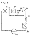
- Japanese Utility Model Publication (examined) No. 58-35979 discloses another conventional refrigerator employing a refrigerating cycle as shown in Fig. 2.
- 41 is a compressor, 42 a condenser, 43 a first capillary serving as a means to reduce pressure, 44 a first evaporator for cooling a refrigerator compartment, 45 a second evaporator for cooling a freezer compartment, and 46 a channel control valve.
- 47 is a second (bypass) capillary connecting a flow-dividing portion 48 positioned between the first capillary 43 and the channel control valve 46 with a flow-merging portion 49 positioned between the first evaporator 44 and the second evaporator 45.
- 50 is a third capillary provided between the channel control valve 46 and the first evaporator 44.
- the refrigerating cycle is repeatedly started and stopped in order to cool a freezer compartment and a refrigerator compartment (not shown) and to maintain them at comparatively low temperatures.
- a refrigerant compressed by the compressor 41 is condensed and liquefied in the condenser 42.
- the channel control valve 46 is opened, the condensed refrigerant, whose pressure is lowered by the first capillary 43, reaches the flow-dividing portion 48 in a medium-pressure state.
- the refrigerant is then divided at the flow-dividing portion 48 to flow through the second capillary 47 and the third capillary 50.
- Part of the refrigerant is reduced in pressure by the third capillary 50, vaporized or gasified by the first evaporator 44 and the second evaporator 45, and reabsorbed by the compressor 41.
- the other part is reduced in pressure by the second capillary 47, merged at the flow-merging portion 49, and vaporized or gasified by the second evaporator 45.
- the third capillary 50 has a much lower resistance than does the second capillary 47 and, hence, most of the refrigerant passes through the third capillary 50 when the channel control valve 46 is open.
- the channel control valve 46 when the channel control valve 46 is in a dosed state, the condensed refrigerant is reduced in pressure by the first capillary 43 and the second capillary 47, vaporized or gasified by the second evaporator 45, and absorbed by the compressor 41.
- the interior of the refrigerator is cooled by heat exchange with the evaporators whose temperature is lower in comparison with the temperature inside the refrigerator.
- the refrigerant whose pressure has been lowered by the first capillary 43 during the opening of the channel control valve 46 is temporarily expanded when divided at the flow-dividing portion 48, and is then readmitted into the comparatively narrow capillaries.
- the refrigerant at the flow-dividing portion 48 is a two-phase refrigerant composed of a gas and a liquid. Because the refrigerator experiences wide ranging load variations due to changes in the temperature of outside air, the opening and dosing of the door, the introduction and removal of food products, and the like, the flow rate in the capillaries also varies, changing the dryness of the refrigerant at the flow-dividing portion 48.
- the flow rate in a capillary decreases when the gas phase of the refrigerant enters an inlet portion thereof
- the flow rate of the third capillary 50 which normally allows essentially all of the refrigerant to pass through, sometimes decreases and the flow rate through the second capillary 47 increases when a difference in resistance arises between the second capillary 47 and the third capillary 50; for example, when one of them is filled with a liquid and the other is in a state in which a gas enters the inlet portion.
- a disadvantage is that due to such flow rate variations, the flow rate of the refrigerant through the first evaporator 44, which is used for the cooling of the refrigerator compartment, is insufficient when such cooling is needed, and the refrigerator compartment is not cooled properly.
- Another disadvantage is that because the heat capacity from the flow-dividing portion 48 to the channel control valve 46 is comparatively high, these portions are heated by the ambient temperature when the compressor 41 is stopped, dryness is enhanced during operation, the flow rate into the comparatively narrow capillaries decreases, and the cooling performance is adversely affected.
- the medium pressure of the flow-dividing portion 48 is set high in comparison with the vaporization pressure of the evaporator in order to reduce the frosting of the channel control valve 46, so the third capillary 50 must have a predetermined resistance value (resistance value dose to the first capillary 43), and the second capillary 47 must have an even higher resistance value in order to divide the flow when the channel control valve 46 is open.
- the total resistance value of the capillaries is such that a series connection is established between the first capillary 43 and the second capillary 47 when the channel control valve 46 is closed, and a combination of a series connection with the first capillary 43 and a parallel connection between the third capillary 50 and the second capillary 47 is formed when the channel control valve 46 is opened.
- the cooling system circuits can be switched by opening and dosing the channel control valve 46, but when a switchover is made from a circuit that passes through the first evaporator 44 for the cooling of the refrigerator compartment to a circuit that creates a bypass through the second evaporator 45 for the cooling of the freezer compartment, the refrigerant present in the first evaporator 44 moves into the second evaporator 45, and if the arrangement is such that the first evaporator 44 is disposed below the second evaporator 45, or the line-pass pattern of the first evaporator 44 has a structure in which a liquid trap is formed (for example, a structure whose pass pattern is such that a plurality of rows or tube runs go from top to bottom and then back to the top), the refrigerant is propelled as a result of vaporization and condensation rather than being propelled directly in the liquid state, so a comparatively long time elapses and the machine oil tends to make a stay, necessitating an increase in the
- a top-freezer refrigerator is configured such that the first evaporator is disposed below the second evaporator but because the refrigerant and the machine oil present in the first evaporator when the channel control valve is closed have difficulty returning to the first evaporator in the top position and tend to make a stay due to the effect of gravity, the system tends to operate with an insufficient amount of refrigerant or machine oil following valve switching, creating drawbacks in terms of cooling performance or compressor reliability.
- a drawback therefore, is that a gas deficit is created during the switching of the channel control valve 46, or the refrigerant must be sealed in a larger amount, leading to increased electric consumption and higher costs.
- Still another drawback is that the cooling system must be welded in a larger number of locations, and costs are increased as a result of increased labor requirements.
- Patent specification WO-A-96/15413 discloses a refrigerator according to the preamble of claim 1.
- a refrigerator is known from German utility model 84 24 330. This refrigerator comprises two evaporators and a refrigerant control valve allowing by pass of the evaporator of the refrigerator compartment.
- the present invention has been developed to overcome the above-described disadvantages.
- Another objective of the present invention is to provide an improved refrigerator capable of properly regulating the temperature within a low-temperature storage chamber independently of load variations and preventing a refrigerator compartment from reducing in temperature below a set value.
- the refrigerant or machine oil inside the first evaporator gradually returns to the second evaporator in the direction of gravity when the supply of refrigerant to the first evaporator is stopped by the switching of the channel control valve.
- a smooth return of the refrigerant is thus facilitated, and it is unlikely that the refrigerant stays the first evaporator, preventing the cooling performance or reliability from being adversely affected while avoiding situations in which the system operates with a shortage of the refrigerant or machine oil.
- Fig. 3 depicts a first embodiment of a bottom-freezer refrigerator according to the present invention.
- the refrigerator includes a refrigerator body 150 having a refrigerator compartment 163 and a freezer compartment 162 both defined therein at upper and lower portions thereof, respectively.
- the refrigerator compartment 163 and the freezer compartment 162 are opened and dosed by respective doors (not shown) hingedly mounted on a front surface of the refrigerator body 150.
- a compressor 151, a condenser 152, a first capillary 153 (first pressure reduction means), a self-holding motor-operated valve 156 (channel control valve), a first evaporator 154, and a second evaporator 155 are sequentially connected into a refrigerating cycle 164.
- the refrigerating cycle 164 is also composed of a bypass conduit having a second pressure reduction means 157 for connecting a flow-dividing portion 158 positioned between the first pressure reduction means 153 and the motor-operated valve 156, and a flow-merging portion 159 positioned between the first evaporator 154 and the second evaporator 155.
- the line connecting the motor-operated valve 156, first evaporator 154, and second evaporator 155 has a radius that offers a relatively small resistance to the passage of the refrigerant; for example, a line having roughly the same diameter as lines in the evaporators.
- the first evaporator 154 is located in the refrigerator compartment 163 (for example, on the surface deep inside the refrigerator compartment), and a refrigerator duct 166 and a first motor-operated fan 165 for circulating the internal air of the refrigerator compartment 163 by passing the air through the first evaporator 154 is disposed in the vicinity.
- the second evaporator 165 is located in the freezer compartment 162 (for example, on the surface deep inside the freezer compartment), and a freezer duct 168 and a second motor-operated fan 167 for circulating the internal air of the freezer compartment 162 by passing the air through the second evaporator 155 is disposed in the vicinity.
- the motor-operated valve 156 is disposed inside the refrigerator compartment 163, and the flow-dividing portion 158 is also positioned inside the refrigerator compartment 163 (for example, in the vicinity of the motor-operated valve 156).
- the flow-merging portion 159 is located inside the freezer compartment 162 (for example, in the vicinity of the second evaporator 155).
- the second capillary 157 and the line connecting the second capillary 157, the first evaporator 154, and the second evaporator 155 may be disposed inside or outside the apparatus, it is best to embed these in the heat-insulated walls to reduce the loss of the refrigerating effect.
- the resistance value of the first capillary 153 is such that there is no constriction between the motor-operated valve 156 and the first evaporator 154, making it possible to select a capillary suited to the refrigerating cycle when the motor-operated valve 156 is open.
- the setting is also higher than the total resistance value (pressure loss) of the motor-operated valve 156 and the first evaporator 154.
- the condenser 152 is located at least partially in a machine chamber 169, and is configured for cooling with a third motor-operated fan 170 provided in the vicinity.
- the freezer compartment 162 and the refrigerator compartment 163 are also provided with temperature sensing means (not shown) for sensing the temperature in respective compartments, and with control means (not shown) for controlling the compressor 151, motor-operated valve 156, first motor-operated fan 165, second motor-operated fan 167, and third motor-operated fan 170.
- the temperature sensing means detects that a predetermined temperature presetting has been exceeded.
- the control means receives this signal and actuates the compressor 151, second motor-operated fan 167, third motor-operated fan 170, and motor-operated valve 156.
- the high-temperature, high-pressure refrigerant discharged by the operation of the compressor 151 is condensed and liquefied by the condenser 152 (which is cooled by the motor-operated fan 170), reduced in pressure by the first capillary 153, and delivered to the flow-dividing portion 158.
- the motor-operated valve 156 opens when the temperature sensing means of the refrigerator compartment 163 detects that a predetermined temperature has been exceeded, and closes when the temperature is below the predetermined level.
- the first motor-operated fan 165 is started when the temperature sensing means of the refrigerator compartment 163 detects that a predetermined temperature has been exceeded, and is stopped when the temperature decreases below the predetermined level.
- the motor-operated valve 156 When the motor-operated valve 156 is closed, the refrigerant is admitted through the flow-dividing portion 158 into the second capillary 157, reduced in pressure, and delivered to the second evaporator 155.
- the air inside the freezer compartment 162 is drawn in through the freezer duct 168 by the operation of the second motor-operated fan 167, heat is exchanged thoroughly, and the refrigerant is vaporized and gasified inside the second evaporator 155.
- the gasified refrigerant is again drawn into the compressor 151.
- the heat-exchanged air which by now has a lower temperature, is discharged.
- the compressor 151, second motor-operated fan 167, and third motor-operated fan 170 are stopped by the control means, and the motor-operated valve 156 is actuated and dosed.
- the refrigerant flows from the flow-dividing portion 158 through the motor-operated valve 156, reaches the first evaporator 154, and then enters the second evaporator 155. Furthermore, part of the refrigerant in the flow-dividing portion 158 enters the second capillary 157, unites with the aforementioned refrigerant stream in the flow-merging portion 159, and flows into the second evaporator 155. The refrigerant vaporized and gasified by the first evaporator 154 and second evaporator 155 is readmitted into the compressor 151.
- Th air inside the refrigerator compartment 163 is drawn in through the refrigerator duct 166 by the operation of the first motor-operated fan 165, heat is exchanged thoroughly, and the refrigerant is partially vaporized and gasified inside the first evaporator 154.
- the heat-exchanged air which by now has a comparatively low temperature, is discharged, and the temperature inside the refrigerator compartment 163 is allowed to decrease.
- the temperature sensing means detects that this temperature has decreased below the predetermined temperature, the first motor-operated fan 165 is stopped, and the motor-operated valve 156 is actuated and dosed.
- the freezer compartment 162 is cooled by the operation of the second motor-operated fan 167, and when the temperature sensing means detects that the temperature has dropped below the predetermined level, the compressor 151, second motor-operated fan 167, and third motor-operated fan 170 are stopped by the control means, and the motor-operated valve 156 is actuated and dosed.
- Cooling and temperature adjustment are accomplished by repeating such procedures.
- the motor-operated valve 156 When the motor-operated valve 156 is open, the refrigerant passing through the first capillary 153 flows through the flow-dividing portion 158 and the motor-operated valve 156 without being again restricted by capillaries (comparatively narrow lines) before reaching the first evaporator 154, and a connection is formed using a line whose diameter is roughly the same as that of the evaporators, avoiding situations in which the flow rate into the first evaporator 154 is reduced by the entrainment of a gas-phase refrigerant when the refrigerant flows as a two-phase mixture and the void ratio varies as a result of occasional load changes caused by the ambient temperature conditions of the refrigerating apparatus, replacement of food, opening and dosing of the door, and the like.
- the resistance value of the second pressure reduction means is set higher than the combined resistance value of the channel control valve and the first evaporator (the resistance value of the channel control valve and the evaporator is commonly very low), so the refrigerant proceeds into the first evaporator with virtually no resistance. Cooling performance can thus be enhanced without creating any shortage in terms of the cooling of the refrigerator compartment or the flow rate of the refrigerant entering the aforementioned first evaporator for refrigeration cooling when such refrigeration cooling is required.
- the cooling performance is not reduced in any way because the manner in which the flow is divided does not change when the state of the refrigerant is changed by the heat effects demonstrated in the vicinity of the channel control valve.
- the resistance value of the second pressure reduction means should be set above the very low combined resistance value of the channel control valve and the first evaporator to prevent the pressure reduction from varying widely due to the opening and dosing of the channel control valve.
- the reduced-pressure resistance of the refrigerating cycle can thus be optimized, and system efficiency increased.
- a self-holding motor-operated valve was described as the channel control valve, but a low-cost solenoid valve, which has a simple structure and is easy to control, may also be used.
- Embedding the motor-operated valve 156, the flow-dividing portion 158, and the flow-merging portion 159 in a heat-insulated wall is effective for preventing frost from forming on the motor-driven valve or the like.
- the condenser may also be disposed outside the back surface of the refrigerator and cooled by natural convection.
- the same effect can be obtained with a so-called inner condenser, in which lines are placed between the back surface and the heat-insulated wall.
- Fig. 5 depicts a second embodiment of a bottom-freezer refrigerator according to the present invention.
- Fig. 5 depicts a second embodiment of a bottom-freezer refrigerator according to the present invention.
- a heat exchanger 172 is provided for exchanging heat between the first capillary 153 and a suction pipe 171 connecting the second evaporator 155 and the compressor 151.
- This heat exchanger 172 is embedded in a heat-insulated section on the back surface of the refrigerator body 150.
- the second capillary 157 is embedded in a heat-insulated material without any heat exchange.
- the heat exchanger 172 may be bundled dose together with the aid of a tape or the like to prevent penetration of the heat-insulated material. Improvement of heat transfer by soldering is desired.
- Heat exchange is thus performed with the first capillary 153 before the refrigerant leaving the second evaporator 155 returns to the compressor 151, and a higher temperature is established in the line leading to the compressor 151 and being in contact with air in the vicinity thereof, making it possible to prevent condensation and arresting the formation of water drops.
- cooling the refrigerant in the first capillary 153 enhances the cooling effect of the refrigerating cycle 164 and provides better cooling performance.
- Another feature is that the second capillary 157 is not subjected to heat exchange because when such heat exchange is performed, variations in the amount of heat exchanged during the opening of the motor-operated valve 156 induce changes in the flow rate of the capillary and cause more refrigerant than necessary to be fed to the second evaporator 155, with the result that the amount in which the refrigerant is fed to the first evaporator 154 is reduced, and the first evaporator 154 delivers an inferior cooling performance.
- Fig. 6 depicts a third embodiment of a bottom-freezer refrigerator according to the present invention.
- Fig. 6 depicts a third embodiment of a bottom-freezer refrigerator according to the present invention.
- a heat exchanger 174 is provided for exchanging heat between the first capillary 153 and a connection pipe 173 connecting the first evaporator 154 and the second evaporator 155.
- This heat exchanger 174 is embedded in a heat-insulated section on the back surface of the refrigerator body 150.
- connection pipe 173 If the line length of the connection pipe 173 is increased, the arrangement of the line Is complicated and liquid traps form or the pressure loss increases, making it desirable that the evaporators be connected over the shortest possible distance. Consequently, the heat-exchange distance is established such that heat exchange is performed over a portion of the comparatively long first capillary 153, that is, 500 to 1000 mm.
- cooling the refrigerant in the first capillary 153 enhances the cooling effect of the refrigerating cycle 164 and provides better cooling performance.
- the refrigerant in the first evaporator 154 moves to the second evaporator 155 when the compressor 151 is stopped or the motor-operated valve 156 is dosed. Because the liquid refrigerant being moved by a pressure difference cools the first capillary 153, the cooling effect of the refrigerating cycle 164 is enhanced, providing better cooling performance.
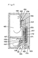
- Fig. 7 schematically depicts the area in the vicinity of the first evaporator 154.
- the freezer compartment 162 is located below the refrigerator compartment 163, and the first evaporator 154 is disposed deep inside the refrigerator compartment 163 and above the second evaporator 155.
- the first capillary 153 and the second capillary 157 are connected at the flow-dividing portion 158, providing a connection to the motor-operated valve 156.
- the motor-operated valve 156 is located above the first evaporator 154, in a void space across from the first motor-operated fan 165.
- a connection is established between the motor-operated valve 156 and the inlet line of the first evaporator 154, and a linear structure is formed according to a pass pattern in which a plurality of tube runs are sequentially arranged in a single direction from the top of the evaporator downward.
- a connection is also established between the outlet line of the first evaporator 154 and the second evaporator 155 via the flow-merging portion 159.
- the evaporators are thus devoid of liquid traps, and the refrigerant present in the first evaporator 154 is smoothly transported to the second evaporator 155 by the pressure difference and gravity when a switchover is made by the opening or dosing of the motor-operated valve 156 from a circuit that passes through the first evaporator 154 for refrigeration cooling to a circuit that creates a bypass through the second evaporator 155 for freezer cooling.
- the efficiency of the refrigerating cycle 164 can therefore be enhanced by avoiding a situation in which a significant gas deficit is produced in the second evaporator 155 for freezer cooling during the switching of the motor-operated valve 156 and the amount of sealed refrigerant must be increased.
- abnormal frosting can be prevented because the motor-operated valve 156 is positioned, in relation to the first evaporator 154, on the downstream side of the air flow created by the first motor-operated fan 165.
- Fig. 8 schematically depicts a modification of the first evaporator 154.
- neighboring tube runs in the first evaporator 154 (fin-coil type) underneath the first motor-operated fan 165 are shifted from each other by a pitch 175 to form a staggered layout in accordance with a pass pattern in which the tube runs are sequentially arranged in a single direction from the top of the evaporator downward, allowing the line to occupy a wider projected area in a cross section perpendicular to the direction of air flow without forming liquid traps in the first evaporator 154.
- the heat-transfer coefficient can be increased by the enhanced turbulence in the line, and the efficiency of the cooling system can be raised.
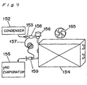
- Fig. 9 schematically depicts another modification of the arrangement of Fig. 7.
- the flow-dividing portion 158, the second capillary 157, and the flow-merging portion 159 are disposed in the refrigerator compartment 163, and the flow-merging portion 159 is placed in the vicinity of the outlet line of the first evaporator 154.
- first evaporator 154, motor-operated valve 156, second capillary 157, flow-dividing portion 158, and flow-merging portion 159 are integrated into a single unit, this sub-assembled unit can be incorporated into the system itself merely by performing welding at two locations. It is also possible to cut down on labor and to improve welding reliability.
- Fig. 10 depicts a fourth embodiment of a bottom-freezer refrigerator according to the present invention.
- the refrigerator shown in Fig. 10 includes a refrigerator body 150 having at least one freezer compartment 162, at least one refrigerator compartment 163 provided above the freezer compartment 162, and a machine chamber 169 provided at a bottom portion of the back surface of the freezer compartment 162.
- a first evaporator 154 and a motor-operated fan 165 serving as a first cold air circulation means are mounted on the back surface of the refrigerator compartment 163.
- a motor-operated valve 156 serving as a channel control means is provided above the first evaporator 154, and a motor-operated fan 167 (second cold air circulation means) and a second evaporator 155 are mounted on the back surface of the freezer compartment 162 above the machine chamber 169.
- the refrigerant or the machine oil inside the first evaporator 154 gradually returns to the second evaporator 155 in the direction of gravity when the supply of refrigerant to the first evaporator 154 is stopped by the switching of the motor-operated valve 156.
- a smooth return of the refrigerant is thus facilitated, and it is unlikely that the refrigerant stays the first evaporator 154, preventing the cooling performance or reliability from being adversely affected while avoiding situations in which the system operates with a shortage of the refrigerant or machine oil.
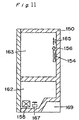
- Fig. 11 depicts a fifth embodiment of a bottom-freezer refrigerator according to the present invention.
- a first evaporator 154 and a first motor-operated fan 165 are mounted on the back surface of a refrigerator compartment 163, while a second evaporator 155 and a second motor-operated fan 167 are mounted on a bottom portion of a freezer compartment 162 in front of a machine chamber 169.
- the interior of the freezer compartment 162 can be used freely as a storage space, and the difficult-to-use portion of the bottom of the refrigerator body 150 can be used as a space for accommodating the machine chamber 169 and the second evaporator 155, making it possible to configure the inactive capacity in a more efficient manner.
- the bottom In the case of a drawer-type freezer compartment, the bottom can be made flat all the way to the back surface, increasing the usable internal capacity in practical terms.
Landscapes
- Engineering & Computer Science (AREA)
- Physics & Mathematics (AREA)
- Mechanical Engineering (AREA)
- Thermal Sciences (AREA)
- General Engineering & Computer Science (AREA)
- Chemical & Material Sciences (AREA)
- Combustion & Propulsion (AREA)
- Devices That Are Associated With Refrigeration Equipment (AREA)
- Cold Air Circulating Systems And Constructional Details In Refrigerators (AREA)
Description
Claims (2)
- A refrigerator having a refrigerator compartment (163), a freezer compartment (162), and a machine chamber (169) all defined therein, said refrigerator comprising:a first cold air circulation means (165) and a first evaporator (154) both located on a surface deep inside said refrigerator compartment (163); anda second cold air circulation means (167) and a second evaporator (155) both located on a surface deep inside said freezer compartment (162),said refrigerator compartment (163) being formed above said freezer compartment (162), said machine chamber (169) being formed at a lower portion of said freezer compartment (162) and said second evaporator (155) being disposed below said first evaporator (154), characterized in that the first evaporator (154) and a refrigerant channel control valve (156) are positioned within a refrigerator air duct (166) formed in said refrigerator compartment (163), the refrigerant channel control valve being disposed downstream of said first evaporator (154) with respect to the direction of flow of the air inside said duct (166).
- The refrigerator according to claim 1,
wherein said channel control valve (156) is disposed adjacent said first cold air circulation means (165).
Applications Claiming Priority (5)
| Application Number | Priority Date | Filing Date | Title |
|---|---|---|---|
| JP3840598 | 1998-02-20 | ||
| JP3840598 | 1998-02-20 | ||
| JP3994998 | 1998-02-23 | ||
| JP3994998 | 1998-02-23 | ||
| PCT/JP1999/000682 WO1999042770A1 (en) | 1998-02-20 | 1999-02-17 | Refrigerator having a cooler mounted in each of a refrigerator compartment and a freezer compartment |
Publications (2)
| Publication Number | Publication Date |
|---|---|
| EP1056979A1 EP1056979A1 (en) | 2000-12-06 |
| EP1056979B1 true EP1056979B1 (en) | 2003-10-08 |
Family
ID=26377651
Family Applications (1)
| Application Number | Title | Priority Date | Filing Date |
|---|---|---|---|
| EP99905207A Expired - Lifetime EP1056979B1 (en) | 1998-02-20 | 1999-02-17 | Refrigerator having a cooler mounted in each of a refrigerator compartment and a freezer compartment |
Country Status (10)
| Country | Link |
|---|---|
| US (1) | US6327867B1 (en) |
| EP (1) | EP1056979B1 (en) |
| JP (1) | JP2002504661A (en) |
| KR (1) | KR100381684B1 (en) |
| CN (2) | CN1570526A (en) |
| AU (1) | AU2546899A (en) |
| DE (1) | DE69911925T2 (en) |
| MY (1) | MY125170A (en) |
| TW (1) | TW446106U (en) |
| WO (1) | WO1999042770A1 (en) |
Families Citing this family (71)
| Publication number | Priority date | Publication date | Assignee | Title |
|---|---|---|---|---|
| CH694472A5 (en) * | 2000-05-04 | 2005-01-31 | Forster Ag Hermann | Fridge. |
| ITPN20000074A1 (en) * | 2000-12-04 | 2002-06-04 | Zanussi Elettromecc | REFRIGERATOR APPLIANCE WITH A MULTIPLE OF COMPARTMENTS |
| KR100431342B1 (en) * | 2001-03-26 | 2004-05-12 | 삼성전자주식회사 | Kimchi-Refrigerator and Control Method thereof |
| AU2001262621B2 (en) * | 2001-05-24 | 2007-03-01 | M.E.S. Medical Electronic Systems Ltd. | Semen analysis |
| DE10139834A1 (en) * | 2001-08-14 | 2003-02-27 | Bsh Bosch Siemens Hausgeraete | Refrigeration device and operating method for a refrigeration device |
| KR100451221B1 (en) * | 2001-11-16 | 2004-10-02 | 엘지전자 주식회사 | Direct cooling type refrigerator using combustibility refrigerants |
| KR100453236B1 (en) * | 2001-11-27 | 2004-10-15 | 삼성전자주식회사 | Refrigerator having a multipurpose room thereof control method |
| US6725680B1 (en) * | 2002-03-22 | 2004-04-27 | Whirlpool Corporation | Multi-compartment refrigerator control algorithm for variable speed evaporator fan motor |
| DE10235783B4 (en) | 2002-08-05 | 2008-02-14 | BSH Bosch und Siemens Hausgeräte GmbH | Refrigeration unit with fan and control method for it |
| KR100638103B1 (en) * | 2002-11-06 | 2006-10-25 | 삼성전자주식회사 | Cooling system |
| KR20040084418A (en) * | 2003-03-28 | 2004-10-06 | 삼성전자주식회사 | Refrigerator |
| US7032407B2 (en) * | 2003-06-27 | 2006-04-25 | General Electric Company | Methods and apparatus for refrigerator compartment |
| JP4329815B2 (en) * | 2004-03-04 | 2009-09-09 | パナソニック株式会社 | refrigerator |
| BRPI0402013A (en) * | 2004-05-04 | 2005-12-20 | Multibras Eletrodomesticos Sa | Refrigeration control system in combination refrigerators |
| US7331193B2 (en) * | 2004-08-13 | 2008-02-19 | Samsung Electronics Co., Ltd. | Refrigerator |
| DE202004019713U1 (en) * | 2004-12-21 | 2005-04-07 | Dometic Gmbh | A refrigeration appliance for leisure vehicles has an insertable divider to separate the interior into two separate spaces |
| US20060130513A1 (en) * | 2004-12-22 | 2006-06-22 | Samsung Electronics Co., Ltd. | Refrigerator |
| KR100726456B1 (en) * | 2005-09-24 | 2007-06-11 | 삼성전자주식회사 | Refrigerator |
| KR100761357B1 (en) * | 2006-07-21 | 2007-09-27 | 주식회사 대우일렉트로닉스 | Cold Air Circulation Structure of Refrigerator with Temperature Switching Room and Its Control Method |
| KR20080014559A (en) | 2006-08-11 | 2008-02-14 | 삼성전자주식회사 | Refrigerator |
| US7497663B2 (en) * | 2006-10-26 | 2009-03-03 | General Electric Company | Rotor blade profile optimization |
| KR100808180B1 (en) * | 2006-11-09 | 2008-02-29 | 엘지전자 주식회사 | Refrigeration cycle unit and refrigerator |
| KR100826180B1 (en) * | 2006-12-26 | 2008-04-30 | 엘지전자 주식회사 | Refrigerator and its control method |
| US7762102B2 (en) * | 2006-12-28 | 2010-07-27 | General Electric Company | Soft freeze assembly for a freezer storage compartment |
| KR100873140B1 (en) * | 2007-03-31 | 2008-12-09 | 엘지전자 주식회사 | Refrigerator |
| KR101283190B1 (en) * | 2007-07-31 | 2013-07-05 | 엘지전자 주식회사 | Refrigerator with evaporator installed in door |
| DE202007014888U1 (en) * | 2007-10-05 | 2009-02-19 | Liebherr-Hausgeräte Ochsenhausen GmbH | Fridge and / or freezer |
| DE202007017691U1 (en) * | 2007-10-08 | 2009-02-26 | Liebherr-Hausgeräte Ochsenhausen GmbH | Fridge and / or freezer |
| DE202009006300U1 (en) * | 2009-02-25 | 2010-07-29 | Liebherr-Hausgeräte Ochsenhausen GmbH | Fridge and / or freezer |
| ES2377620B1 (en) * | 2009-04-07 | 2013-03-19 | Fagor, S. Coop. | REFRIGERATOR APPARATUS WITH COMPARTMENT WITH ADJUSTABLE TEMPERATURE. |
| US8011191B2 (en) | 2009-09-30 | 2011-09-06 | Thermo Fisher Scientific (Asheville) Llc | Refrigeration system having a variable speed compressor |
| US8011201B2 (en) * | 2009-09-30 | 2011-09-06 | Thermo Fisher Scientific (Asheville) Llc | Refrigeration system mounted within a deck |
| JP2012021400A (en) * | 2010-07-12 | 2012-02-02 | Hitachi Appliances Inc | Sealed type compressor and refrigerator equipped therewith |
| KR20120006699A (en) * | 2010-07-13 | 2012-01-19 | 삼성전자주식회사 | Refrigerator |
| DE102011053894A1 (en) * | 2010-11-23 | 2012-05-24 | Visteon Global Technologies, Inc. | Refrigeration system with refrigerant evaporator arrangement and method for parallel air and battery contact cooling |
| EP2520881A1 (en) * | 2011-05-06 | 2012-11-07 | Whirpool Corporation | A refrigeration system and method for refrigerating two compartments with evaporators in series |
| DE102011075946A1 (en) * | 2011-05-17 | 2012-11-22 | BSH Bosch und Siemens Hausgeräte GmbH | Refrigerating appliance e.g. household refrigerating appliance has control circuit, temperature sensor and timer that are arranged within storage chamber for reversing air circulation direction at operating phase of evaporator |
| AU2011375631B2 (en) * | 2011-08-25 | 2015-05-21 | Hefei Hualing Co., Ltd. | Refrigerator |
| RU2622352C2 (en) * | 2011-12-12 | 2017-06-14 | Индезит Компани С.П.А. | Method and device for managing the cooling device and cooling unit that realizes the mentioned method |
| EP2613111A3 (en) * | 2012-01-03 | 2015-07-01 | Indesit Company Beyaz Esya Sanayi ve Ticaret Anonim Sirketi | A refrigerator |
| US8925346B2 (en) | 2012-02-07 | 2015-01-06 | Thermo Fisher Scientific (Asheville) Llc | High performance freezer having cylindrical cabinet |
| US9140479B2 (en) | 2012-05-21 | 2015-09-22 | Whirlpool Corporation | Synchronous temperature rate control and apparatus for refrigeration with reduced energy consumption |
| US9140477B2 (en) | 2012-05-21 | 2015-09-22 | Whirlpool Corporation | Synchronous compartment temperature control and apparatus for refrigeration with reduced energy consumption |
| US9140478B2 (en) | 2012-05-21 | 2015-09-22 | Whirlpool Corporation | Synchronous temperature rate control for refrigeration with reduced energy consumption |
| JP6017886B2 (en) * | 2012-08-24 | 2016-11-02 | シャープ株式会社 | refrigerator |
| US20140298854A1 (en) * | 2013-04-04 | 2014-10-09 | General Electric Company | Dual evaporator refrigeration system with zeotropic refrigerant mixture |
| EP2835601B1 (en) * | 2013-08-06 | 2017-10-04 | LG Electronics Inc. | Refrigerator and control method thereof |
| CN103983070B (en) * | 2014-05-06 | 2016-08-24 | 合肥美的电冰箱有限公司 | The control method of refrigerator air door, the control device of refrigerator air door and wind cooling refrigerator |
| KR102267881B1 (en) | 2014-12-01 | 2021-06-23 | 삼성전자주식회사 | Refrigerator |
| JP2016136082A (en) | 2015-01-05 | 2016-07-28 | 三星電子株式会社Samsung Electronics Co.,Ltd. | Cooling system |
| US9946223B2 (en) * | 2015-07-08 | 2018-04-17 | Ricoh Company, Ltd. | Cooling device and image forming apparatus incorporating the cooling device |
| JP6569339B2 (en) * | 2015-07-08 | 2019-09-04 | 株式会社リコー | Cooling device and image forming apparatus |
| KR102480701B1 (en) * | 2015-07-28 | 2022-12-23 | 엘지전자 주식회사 | Refrigerator |
| US10088218B2 (en) * | 2015-09-02 | 2018-10-02 | Lg Electronics Inc. | Refrigerator and control method thereof |
| BR102016020173A2 (en) * | 2016-08-31 | 2018-03-20 | Celso Vantil Julio | INDOOR DRINK COOLING COMPARTMENT OR FREEZER |
| CN106568269B (en) * | 2016-10-24 | 2019-08-27 | 青岛海尔股份有限公司 | refrigerator |
| KR101916727B1 (en) * | 2017-01-19 | 2018-11-08 | 엘지전자 주식회사 | Refrigerator and controlling method thereof |
| PL3732413T3 (en) * | 2017-12-25 | 2024-02-19 | Arçelik Anonim Sirketi | A cooler comprising a heat controlled special compartment |
| CN110094924B (en) * | 2018-01-31 | 2021-09-17 | 日立环球生活方案株式会社 | Refrigerator with a door |
| KR102614564B1 (en) * | 2018-03-08 | 2023-12-18 | 엘지전자 주식회사 | Refrigerator and controlling method the same |
| US11450168B2 (en) | 2018-06-27 | 2022-09-20 | The Coca-Cola Company | Product accommodating device |
| EP3674631B1 (en) * | 2018-12-28 | 2024-04-24 | LG Electronics Inc. | Refrigerator and method for controlling the same |
| KR102679302B1 (en) | 2019-01-10 | 2024-07-01 | 엘지전자 주식회사 | Refrigerator |
| KR102665398B1 (en) | 2019-01-10 | 2024-05-13 | 엘지전자 주식회사 | Refrigerator |
| JP7148416B2 (en) * | 2019-01-10 | 2022-10-05 | 東芝ライフスタイル株式会社 | refrigerator |
| KR102630194B1 (en) | 2019-01-10 | 2024-01-29 | 엘지전자 주식회사 | Refrigerator |
| US11480382B2 (en) * | 2019-01-10 | 2022-10-25 | Lg Electronics Inc. | Refrigerator |
| KR102678956B1 (en) * | 2019-02-28 | 2024-06-28 | 엘지전자 주식회사 | Control method for refrigerator |
| DE102019207919A1 (en) | 2019-05-29 | 2020-12-03 | Dometic Sweden Ab | Hinge mechanism, compartment door arrangement with such a hinge mechanism, cabinet or refrigerator with such a hinge mechanism and / or compartment door arrangement, and recreational vehicle |
| KR20220132305A (en) * | 2021-03-23 | 2022-09-30 | 삼성전자주식회사 | Refrigerator and its control method |
| CN115808048B (en) * | 2021-09-15 | 2024-08-13 | 青岛海尔电冰箱有限公司 | Air-cooled refrigerator and control method thereof |
Family Cites Families (21)
| Publication number | Priority date | Publication date | Assignee | Title |
|---|---|---|---|---|
| US2487012A (en) * | 1946-01-08 | 1949-11-01 | Philco Corp | Refrigeration system |
| US3084519A (en) * | 1958-03-06 | 1963-04-09 | Whirlpool Co | Two temperature forced air refrigerator systems |
| DE1227921B (en) * | 1962-04-19 | 1966-11-03 | Siemens Elektrogeraete Gmbh | Refrigerator with a compression refrigeration machine in the lower part |
| US3382683A (en) * | 1966-11-14 | 1968-05-14 | American Motors Corp | Refrigerating apparatus-single evaporator |
| DE2458981C2 (en) * | 1974-12-13 | 1985-04-18 | Bosch-Siemens Hausgeräte GmbH, 7000 Stuttgart | Refrigerated cabinets, especially no-frost refrigerators |
| JPS5835979A (en) | 1981-08-28 | 1983-03-02 | Matsushita Electric Ind Co Ltd | Semiconductor device |
| IT1178089B (en) * | 1984-01-20 | 1987-09-09 | Merloni Elettrodomestici Spa | REFRIGERANT REFRIGERANT SYSTEM WITH DIFFERENTIATED SYSTEM FOR FREEZER AND REFRIGERATOR |
| US4543799A (en) * | 1984-08-23 | 1985-10-01 | General Electric Company | Household refrigerator with air circulating and cooling arrangement |
| US5157941A (en) * | 1991-03-14 | 1992-10-27 | Whirlpool Corporation | Evaporator for home refrigerator |
| JPH0571850A (en) * | 1991-09-11 | 1993-03-23 | Matsushita Refrig Co Ltd | Freezing refrigerator |
| KR960004503B1 (en) * | 1991-09-26 | 1996-04-06 | 삼성전자주식회사 | Refrigerator for kimchi |
| US5388427A (en) * | 1992-09-23 | 1995-02-14 | Samsung Electronics Co., Ltd. | Refrigerator with kimchi compartment |
| TW326488B (en) * | 1994-06-02 | 1998-02-11 | Samsung Electronics Co Ltd | Refrigerator |
| EP0984232B1 (en) * | 1994-11-11 | 2002-12-18 | Samsung Electronics Co., Ltd. | Control method of a refrigerator having high efficiency multi-evaporator cycle (h.m.cycle) |
| US5600966A (en) * | 1995-05-19 | 1997-02-11 | Forma Scientific, Inc. | Ultra low temperature split door freezer |
| KR0152148B1 (en) * | 1995-08-19 | 1998-11-02 | 김광호 | A refrigerator |
| KR0159699B1 (en) * | 1996-06-12 | 1999-01-15 | 김광호 | Refrigerator |
| SG50772A1 (en) * | 1996-10-16 | 2000-06-20 | Whirlpool Co | Multi-compartment refrigeration system |
| US5896753A (en) * | 1996-10-18 | 1999-04-27 | Lg Electronics Inc. | Freezing cycle apparatus having quick freezing and thawing functions |
| US5870900A (en) * | 1997-06-04 | 1999-02-16 | Maytag Corporation | Thermal capacitive control system for a multi-compartment refrigerator |
| KR100222942B1 (en) * | 1997-07-31 | 1999-10-01 | 윤종용 | Refrigerator having air distribution apparatus |
-
1999
- 1999-02-12 TW TW088202711U patent/TW446106U/en not_active IP Right Cessation
- 1999-02-17 WO PCT/JP1999/000682 patent/WO1999042770A1/en not_active Ceased
- 1999-02-17 EP EP99905207A patent/EP1056979B1/en not_active Expired - Lifetime
- 1999-02-17 KR KR10-2000-7009234A patent/KR100381684B1/en not_active Expired - Lifetime
- 1999-02-17 DE DE69911925T patent/DE69911925T2/en not_active Expired - Fee Related
- 1999-02-17 AU AU25468/99A patent/AU2546899A/en not_active Abandoned
- 1999-02-17 CN CNA2004100557261A patent/CN1570526A/en active Pending
- 1999-02-17 US US09/622,622 patent/US6327867B1/en not_active Expired - Lifetime
- 1999-02-17 CN CNB998031631A patent/CN1296667C/en not_active Expired - Lifetime
- 1999-02-17 JP JP2000532670A patent/JP2002504661A/en active Pending
- 1999-02-19 MY MYPI99000592A patent/MY125170A/en unknown
Also Published As
| Publication number | Publication date |
|---|---|
| CN1296667C (en) | 2007-01-24 |
| TW446106U (en) | 2001-07-11 |
| CN1291277A (en) | 2001-04-11 |
| MY125170A (en) | 2006-07-31 |
| DE69911925T2 (en) | 2004-09-09 |
| EP1056979A1 (en) | 2000-12-06 |
| US6327867B1 (en) | 2001-12-11 |
| JP2002504661A (en) | 2002-02-12 |
| WO1999042770A1 (en) | 1999-08-26 |
| KR20010041178A (en) | 2001-05-15 |
| KR100381684B1 (en) | 2003-04-26 |
| DE69911925D1 (en) | 2003-11-13 |
| CN1570526A (en) | 2005-01-26 |
| AU2546899A (en) | 1999-09-06 |
Similar Documents
| Publication | Publication Date | Title |
|---|---|---|
| US6327867B1 (en) | Refrigerator having a cooler mounted in each of a refrigerator compartment and a freezer compartment | |
| KR101649624B1 (en) | Refrigerator | |
| US4918936A (en) | Refrigerating cycle utilizing cold accumulation material | |
| KR101631904B1 (en) | Refrigerator | |
| EP2339276B1 (en) | Refrigerator | |
| CN100398948C (en) | Refrigerating machine | |
| JP2774486B2 (en) | Refrigerator and operation control method thereof | |
| EP2868997B1 (en) | Refrigerator | |
| JP3452781B2 (en) | refrigerator | |
| JP4206792B2 (en) | refrigerator | |
| CN113237280A (en) | A kind of refrigerator | |
| JP4103384B2 (en) | refrigerator | |
| JP2002081839A (en) | Refrigerator | |
| CN1155787C (en) | Refrigerating machine | |
| JP3404313B2 (en) | refrigerator | |
| JPH07294089A (en) | Frost reduction device for refrigerator | |
| KR100249195B1 (en) | Refrigerator | |
| CN109751814A (en) | Refrigerating device and its control method | |
| JP2003222458A (en) | Refrigerator | |
| JPH0783556A (en) | Frost reduction device for refrigerator | |
| JP2000266445A (en) | refrigerator | |
| KR0176871B1 (en) | Cold air circulation structure of the refrigerator | |
| KR100377748B1 (en) | The cool-air supplying structure for refrigerators | |
| KR19990034525A (en) | Condenser of refrigerator | |
| KR20230010389A (en) | operating method for a refrigerator |
Legal Events
| Date | Code | Title | Description |
|---|---|---|---|
| PUAI | Public reference made under article 153(3) epc to a published international application that has entered the european phase |
Free format text: ORIGINAL CODE: 0009012 |
|
| 17P | Request for examination filed |
Effective date: 20000920 |
|
| AK | Designated contracting states |
Kind code of ref document: A1 Designated state(s): DE FR GB IT SE |
|
| 17Q | First examination report despatched |
Effective date: 20010427 |
|
| GRAH | Despatch of communication of intention to grant a patent |
Free format text: ORIGINAL CODE: EPIDOS IGRA |
|
| GRAS | Grant fee paid |
Free format text: ORIGINAL CODE: EPIDOSNIGR3 |
|
| GRAA | (expected) grant |
Free format text: ORIGINAL CODE: 0009210 |
|
| RAP1 | Party data changed (applicant data changed or rights of an application transferred) |
Owner name: MATSUSHITA REFRIGERATION COMPANY |
|
| AK | Designated contracting states |
Kind code of ref document: B1 Designated state(s): DE FR GB IT SE |
|
| REG | Reference to a national code |
Ref country code: GB Ref legal event code: FG4D |
|
| REF | Corresponds to: |
Ref document number: 69911925 Country of ref document: DE Date of ref document: 20031113 Kind code of ref document: P |
|
| REG | Reference to a national code |
Ref country code: SE Ref legal event code: TRGR |
|
| ET | Fr: translation filed | ||
| PLBE | No opposition filed within time limit |
Free format text: ORIGINAL CODE: 0009261 |
|
| STAA | Information on the status of an ep patent application or granted ep patent |
Free format text: STATUS: NO OPPOSITION FILED WITHIN TIME LIMIT |
|
| 26N | No opposition filed |
Effective date: 20040709 |
|
| PGFP | Annual fee paid to national office [announced via postgrant information from national office to epo] |
Ref country code: DE Payment date: 20060209 Year of fee payment: 8 |
|
| PGFP | Annual fee paid to national office [announced via postgrant information from national office to epo] |
Ref country code: FR Payment date: 20060220 Year of fee payment: 8 |
|
| PGFP | Annual fee paid to national office [announced via postgrant information from national office to epo] |
Ref country code: IT Payment date: 20060228 Year of fee payment: 8 |
|
| PG25 | Lapsed in a contracting state [announced via postgrant information from national office to epo] |
Ref country code: SE Free format text: LAPSE BECAUSE OF NON-PAYMENT OF DUE FEES Effective date: 20070218 |
|
| EUG | Se: european patent has lapsed | ||
| GBPC | Gb: european patent ceased through non-payment of renewal fee |
Effective date: 20070217 |
|
| REG | Reference to a national code |
Ref country code: FR Ref legal event code: ST Effective date: 20071030 |
|
| PG25 | Lapsed in a contracting state [announced via postgrant information from national office to epo] |
Ref country code: DE Free format text: LAPSE BECAUSE OF NON-PAYMENT OF DUE FEES Effective date: 20070901 |
|
| PGFP | Annual fee paid to national office [announced via postgrant information from national office to epo] |
Ref country code: SE Payment date: 20060207 Year of fee payment: 8 |
|
| PG25 | Lapsed in a contracting state [announced via postgrant information from national office to epo] |
Ref country code: GB Free format text: LAPSE BECAUSE OF NON-PAYMENT OF DUE FEES Effective date: 20070217 Ref country code: FR Free format text: LAPSE BECAUSE OF NON-PAYMENT OF DUE FEES Effective date: 20070228 |
|
| PGFP | Annual fee paid to national office [announced via postgrant information from national office to epo] |
Ref country code: GB Payment date: 20060215 Year of fee payment: 8 |
|
| PG25 | Lapsed in a contracting state [announced via postgrant information from national office to epo] |
Ref country code: IT Free format text: LAPSE BECAUSE OF NON-PAYMENT OF DUE FEES Effective date: 20070217 |