EP1056676B1 - Belt-climbing elevator having drive in counterweight - Google Patents
Belt-climbing elevator having drive in counterweight Download PDFInfo
- Publication number
- EP1056676B1 EP1056676B1 EP99908277A EP99908277A EP1056676B1 EP 1056676 B1 EP1056676 B1 EP 1056676B1 EP 99908277 A EP99908277 A EP 99908277A EP 99908277 A EP99908277 A EP 99908277A EP 1056676 B1 EP1056676 B1 EP 1056676B1
- Authority
- EP
- European Patent Office
- Prior art keywords
- drive
- counterweight
- elevator
- traction
- rope
- Prior art date
- Legal status (The legal status is an assumption and is not a legal conclusion. Google has not performed a legal analysis and makes no representation as to the accuracy of the status listed.)
- Expired - Lifetime
Links
Images


Classifications
-
- B—PERFORMING OPERATIONS; TRANSPORTING
- B66—HOISTING; LIFTING; HAULING
- B66B—ELEVATORS; ESCALATORS OR MOVING WALKWAYS
- B66B11/00—Main component parts of lifts in, or associated with, buildings or other structures
- B66B11/0035—Arrangement of driving gear, e.g. location or support
- B66B11/0045—Arrangement of driving gear, e.g. location or support in the hoistway
- B66B11/0055—Arrangement of driving gear, e.g. location or support in the hoistway on the counterweight
-
- B—PERFORMING OPERATIONS; TRANSPORTING
- B66—HOISTING; LIFTING; HAULING
- B66B—ELEVATORS; ESCALATORS OR MOVING WALKWAYS
- B66B17/00—Hoistway equipment
- B66B17/12—Counterpoises
-
- B—PERFORMING OPERATIONS; TRANSPORTING
- B66—HOISTING; LIFTING; HAULING
- B66B—ELEVATORS; ESCALATORS OR MOVING WALKWAYS
- B66B9/00—Kinds or types of lifts in, or associated with, buildings or other structures
- B66B9/02—Kinds or types of lifts in, or associated with, buildings or other structures actuated mechanically otherwise than by rope or cable
- B66B9/027—Kinds or types of lifts in, or associated with, buildings or other structures actuated mechanically otherwise than by rope or cable by rope climbing devices
Definitions
- the present invention relates to elevator systems and, more particularly, to an elevator guide system requiring less installation and operation space than conventional elevator systems by utilizing combined function structures so that an elevator counterweight houses a drive system.
- the drive system drives a drive rope or member by traction.
- British Standard BS 5655 Part I 1986 defines a traction drive lift as a lift whose ropes are driven by friction.
- the hoistway is an elongated, vertical shaft having a rectangular base in which the elevator car translates.
- the hoistway houses, among other things, the car guide rails which are usually a pair of generally parallel rails, fixed to opposite walls near the center of each wall, and running the approximate length of the hoistway.
- a counterweight having a pair of guide rails is positioned adjacent to a third wall.
- the hoistway houses additional components including terminal landing switches, ropes and sheave arrangements, and buffers for the counterweight and the car.
- the elevator components are located and oriented with precision prior to and during operation.
- the interior walls of the hoistway must be properly dimensioned and aligned, and the physical interface between the hoistway walls and the elevator components must be capable of withstanding varying load during use.
- the guide rails on which the car rides are properly positioned and solidly maintained.
- Guide rails are typically steel, T-shaped sections in sixteen foot lengths.
- the position of guide rails within the hoistway affects the position of the hoisting machine, governor and overhead (machine room) equipment.
- the machine room is typically located directly above the hoistway.
- the machine room houses the hoist machine and governor, the car controller, a positioning device, a motor generator set, and a service disconnect switch.
- EP-A-0 565 516 discloses a traction drive elevator system having the features of the preamble of claim 1.
- a counterweight-drive assembly includes a motor and drive pulley sized to maintain a narrow profile and to be suspended and to move in coordination with an elevator car.
- the counterweight-drive assembly is connected to an elevator car by one or more suspension ropes or belts.
- a traction belt is adapted to engage the drive pulley and is fixed vertically in the hoistway to form the counterweight-drive assembly path.
- a flat rope or belt is used.
- the terms "flat belt” and “flat rope” mean a belt or rope having an aspect ratio of greater than one, where the aspect ratio is the ratio of the belt or rope width to the thickness.
- the counterweight-drive assembly When torque is applied through the drive pulley, the counterweight-drive assembly is caused to move up or down the hoistway. Additional deflection rollers guide the traction belt around the drive pulley to attain sufficient surface contact area and resultant traction. Because a flat belt is used, sufficient traction is achieved with a small diameter drive pulley, thus conserving space.
- a counterweight-drive assembly in another embodiment, includes a modular motor arrangement of four drive motors mounted to a counterweight body. Each motor has a sheave that cooperates with one of two fixed ropes attached at a hoistway ceiling and tensioned at the other end by a spring or tensioning weight.
- the motors and sheaves are preferably positioned at the four corners of the counterweight body.
- the motors and sheaves are proportioned and arranged to minimize thickness of the assembly and, thus, spaced required for mounting and operation.
- the path of the ropes around the upper and lower sheaves provides 360 degree effective wrap around for high traction.
- the use of multiple drive sheaves enables a large collective traction area with small diameter sheaves and small motors, thereby conserving space.
- Another advantage of using multiple drive sheaves and corresponding motors is that, in the event of failure of one motor, the others can continue the operation of the elevator system provided that they are sufficiently powered.
- each can be respectively optimized for its particular function without concern for other performance characteristics,
- the suspension ropes can be optimized for tension failure since they are not required to provide a traction medium.
- the traction rope can be optimized for traction with only limited concern for tension failure, as the maximum tension it is subjected to results from the mass difference between the car and the counterweight.
- the use of traction belts enables a reduction in motor size where, for example, cylindrical motors can be implemented instead of flat motors.
- An elevator assembly which does not form part of the present invention is illustrated in Figs. 1-4 for illustrative purposes only.
- An elevator assembly (10) includes an elevator car (12) and a guide rail assembly (14).
- the guide rail assembly (14) comprises an elongated, vertical member (18) having at least two faces for fixing, respectively, a first elevator car guide rail (20) and a first counterweight guide rail (22).
- the vertical member (18) may be attached to a stationary structure such as a wall of the hoistway (not shown).
- a second elevator car guide rail (16) is positioned opposite of and facing the first elevator car guide rail (20).
- the two elevator car guide rails (20, 16) are adapted to slidingly receive the elevator car (12) in a conventional manner through the use of conventional guide shoes (not shown) or the like.
- a second counterweight guide rail (24) is positioned opposite of and facing the first counterweight guide rail (22) in such a way that the two counterweight guide rails (22, 24) lay in a plane that is generally orthogonal to the plane in which the elevator car guide rails (16, 20) lay.
- the counterweight-drive assembly (26) comprises a body (28) housing a drive assembly (30), a motor (32), and weights (34), as shown in Fig.4 .
- Components of the drive assembly (30) are shown schematically in Fig. 3 and include a toothed drive pulley (36) adapted to provide torque from the motor (32), and first and second deflection pulleys (38, 40) for effecting surface contact of the toothed belt (42) along a predetermined surface area of the drive pulley (36) for predetermined traction.
- a system using a toothed belt is not within the scope of the present invention.
- tension varying devices (44, 46) which may be of a conventional type such as springs (not shown).
- a belt-tensioning device (48) is shown schematically and it may also be of a conventional type such as a spring (not shown).
- the motor (32) can be an electric motor and can be supplied power and control signals via a power and control cable (50) as shown, whereby the cable (50) is adapted to move with the counterweight-drive assembly (26).
- a first end (54) of the suspension belt (52) is fixed to a stationary object overhead, such as a beam (56) of the ceiling of the hoistway (not shown).
- a first idler pulley (58) fixed to the counterweight-drive assembly (26) engages the suspension belt (52).
- a second idler pulley (60) fixed to the overhead beam (56) engages the suspension belt (52).
- Third and fourth idler pulleys (62, 64) are fixed to the bottom of the elevator car (12) and also engage the belt (52).
- the third and fourth idler pulleys (62, 64) need not necessarily be positioned under the elevator car (12) and may be, for example, replaced by one or more idler pulleys positioned above the car.
- the second end (64) of the suspension belt (52) is fixed relative to the hoistway (not shown) at a height sufficient to enable desired vertical movement of the elevator car (12) and counterweight-drive asembly (26) as will be described below.
- the length of available belt (52) extending past the second idler pulley (60) is proportionally shortened and the elevator car (12) is caused to be lifted upward on the third and fourth idler pulleys (62, 64).
- the elevator car (12) is lowered as the counterweight-drive assembly (26) is driven upward.
- an embodiment of the present invention is directed to a self-climbing counterweight-drive assembly (100).
- the counterweight-drive assembly (100) can be adapted to be used with a suspension belt (52) and idler (58, 60, 62, 64) arrangement in accordance with Figs. 1-4 or in a similar fashion to couple the assembly (100) with an elevator car (12).
- a suspension belt (52) and idler (58, 60, 62, 64) arrangement in accordance with Figs. 1-4 or in a similar fashion to couple the assembly (100) with an elevator car (12).
- movement of the elevator car (12) will be dependent upon movement of the counterweight-drive assembly (100).
- the counter-weight drive assembly (100) of the this embodiment includes a body (102) having fixed thereon a group of four electric motors (104, 106, 108, 110). Each motor (104-110) is equipped with a corresponding drive sheave (112, 114, 116, 118). A pair of fixed ropes (120, 122) are attached to an overhead structure (not shown) in the hoistway (not shown) and are either fixed or tensioned by conventional means (not shown) at the bottom. As shown specifically in Fig.
- each rope (120, 122) extends downwardly to engage and wrap under a lower drive sheave (118), extends upwardly to engage and wrap over an upper drive sheave (114), and extends downward again to be tensioned or fixed.
- the traction between the ropes (120, 122) and sheaves (112-118) is controlled by adjusting the tension in each respective rope (120, 122).
- the ropes (120, 122) are flat ropes because they are capable of wrapping around small diameter sheaves while supplying sufficient traction. It is then possible to minimize profile thickness of the assembly (100).
- each drive sheave (112-118) is engaged by one of the ropes (120, 122) about 180 degrees and, thus, the total effective wrap angle is about 360 degrees on each side.
- the total wrap angle is determinative of the total traction.
- mounting motors on a counterweight-drive assembly will remove vibration and noise from the car (12).
- the positioning of the drive sheaves (112-118) makes sheave mounting and servicing convenient.
- the ability to use small motors (104-110) provides costs savings.
- a principal feature of the present invention is the flatness of the ropes used in the above described elevator system.
- the increase in aspect ratio results in a rope that has an engagement surface, defined by the width dimension "w", that is optimized to distribute the rope pressure. Therefore, the maximum rope pressure is minimized within the rope.
- the thickness "t1" of the flat rope may be reduced while maintaining a constant cross-sectional area of the portions of the rope supporting the tension load in the rope.
- the flat ropes 722 include a plurality of individual load carrying cords 726 encased within a common layer of coating 728.
- the coating layer 728 separates the individual cords 726 and defines an engagement surface 730 for engaging the traction sheave 724.
- the load carrying cords 726 may be formed from a high-strength, lightweight non-metallic material, such as aramid fibers, or may be formed from a metallic material, such as thin, high-carbon steel fibers. It is desirable to maintain the thickness "d" of the cords 726 as small as possible in order to maximize the flexibility and minimize the stress in the cords 726.
- the fiber diameters should be less than .25 millimeters in diameter and preferably in the range of about .10 millimeters to .20 millimeters in diameter.
- Steel fibers having such diameter improve the flexibility of the cords and the rope.
- the traction sheave diameter "D" may be reduced while maintaining the maximum rope pressure within acceptable limits.
- the engagement surface 730 is in contact with a corresponding surface 750 of the traction sheave 724.
- the coating layer 728 is formed from a polyurethane material, preferably a thermoplastic urethane, that is extruded onto and through the plurality of cords 726 in such a manner that each of the individual cords 726 is restrained against longitudinal movement relative to the other cords 726.
- Other materials may also be used for the coating layer if they are sufficient to meet the required functions of the coating layer: traction, wear, transmission of traction loads to the cords and resistance to environmental factors.
- thermoplastic urethane if they do not meet or exceed the mechanical properties of a thermoplastic urethane, then the benefits resulting from the use of flat ropes may be reduced. With the thermoplastic urethane mechanical properties the traction sheave 724 diameter is reducible to 100 millimeters or less.
- the rope pressure may be distributed more uniformly throughout the rope 722. Because of the incorporation of a plurality of small cords 726 into the flat rope elastomer coating layer 728, the pressure on each cord 726 is significantly diminished over prior art ropes. Cord pressure is decreased at least as n -1 ⁇ 2 , with n being the number of parallel cords in the flat rope, for a given load and wire cross section. Therefore, the maximum rope pressure in the flat rope is significantly reduced as compared to a conventionally roped elevator having a similar load carrying capacity.
- the effective rope diameter 'd' (measured in the bending direction) is reduced for the equivalent load bearing capacity and smaller values for the sheave diameter 'D' may be attained without a reduction in the D/d ratio.
- minimizing the diameter D of the sheave permits the use of less costly, more compact, high speed motors as the drive machine.
- a traction sheave 724 having a traction surface 750 configured to receive the flat rope 722 is also shown in Fig. 7 .
- the engagement surface 750 is complementarily shaped to provide traction and to guide the engagement between the flat ropes 722 and the sheave 724.
- the traction sheave 724 includes a pair of rims 744 disposed on opposite sides of the sheave 724 and one or more dividers 745 disposed between adjacent flat ropes.
- the traction sheave 724 also includes liners 742 received within the spaces between the rims 744 and dividers 745.
- the liners 742 define the engagement surface 750 such that there are lateral gaps 754 between the sides of the flat ropes 722 and the liners 742.
- a traction sheave without liners may be used.
Landscapes
- Engineering & Computer Science (AREA)
- Mechanical Engineering (AREA)
- Structural Engineering (AREA)
- Automation & Control Theory (AREA)
- Civil Engineering (AREA)
- Lift-Guide Devices, And Elevator Ropes And Cables (AREA)
- Cage And Drive Apparatuses For Elevators (AREA)
- Types And Forms Of Lifts (AREA)
Description
- The present invention relates to elevator systems and, more particularly, to an elevator guide system requiring less installation and operation space than conventional elevator systems by utilizing combined function structures so that an elevator counterweight houses a drive system.
- The drive system drives a drive rope or member by traction. British Standard BS 5655 Part I 1986 defines a traction drive lift as a lift whose ropes are driven by friction.
- Known elevator systems typically confine all elevator components to the hoistway or the machine room. The hoistway is an elongated, vertical shaft having a rectangular base in which the elevator car translates. The hoistway houses, among other things, the car guide rails which are usually a pair of generally parallel rails, fixed to opposite walls near the center of each wall, and running the approximate length of the hoistway. A counterweight having a pair of guide rails is positioned adjacent to a third wall. The hoistway houses additional components including terminal landing switches, ropes and sheave arrangements, and buffers for the counterweight and the car.
- It is essential that the elevator components are located and oriented with precision prior to and during operation. The interior walls of the hoistway must be properly dimensioned and aligned, and the physical interface between the hoistway walls and the elevator components must be capable of withstanding varying load during use. It is particularly essential that the guide rails on which the car rides are properly positioned and solidly maintained. For quality of ride and safety, the guide rails need to be precisely plumb, square and spaced to avoid car sway, vibration and knocking. Guide rails are typically steel, T-shaped sections in sixteen foot lengths. The position of guide rails within the hoistway affects the position of the hoisting machine, governor and overhead (machine room) equipment. The machine room is typically located directly above the hoistway. The machine room houses the hoist machine and governor, the car controller, a positioning device, a motor generator set, and a service disconnect switch.
- Because the various components of the hoistway and machine room require precise positioning and they produce varying and substantial loads, it is costly and complicated to assemble a typical traction elevator system.
-
EP-A-0 565 516 discloses a traction drive elevator system having the features of the preamble of claim 1. - It is an object of the present invention to provide an improved elevator system that optimizes use of space by providing a multi-function component that functions as a counterweight and a support for the drive machine and system, so that the need for a machine room and other space-consuming components is eliminated. It is a further object to provide an improved elevator system that achieves optimum efficiency in construction and materials by various means including, for example, providing a counterweight apparatus that stores potential energy as an integral part of the lift arrangement and that reduces the required torque for movement of the elevator car.
- The present invention provides an elevator system as claimed in claim 1. In one embodiment, a counterweight-drive assembly includes a motor and drive pulley sized to maintain a narrow profile and to be suspended and to move in coordination with an elevator car. The counterweight-drive assembly is connected to an elevator car by one or more suspension ropes or belts. A traction belt is adapted to engage the drive pulley and is fixed vertically in the hoistway to form the counterweight-drive assembly path. A flat rope or belt is used. As used herein, the terms "flat belt" and "flat rope" mean a belt or rope having an aspect ratio of greater than one, where the aspect ratio is the ratio of the belt or rope width to the thickness. When torque is applied through the drive pulley, the counterweight-drive assembly is caused to move up or down the hoistway. Additional deflection rollers guide the traction belt around the drive pulley to attain sufficient surface contact area and resultant traction. Because a flat belt is used, sufficient traction is achieved with a small diameter drive pulley, thus conserving space.
- In another embodiment of the present invention, a counterweight-drive assembly includes a modular motor arrangement of four drive motors mounted to a counterweight body. Each motor has a sheave that cooperates with one of two fixed ropes attached at a hoistway ceiling and tensioned at the other end by a spring or tensioning weight. The motors and sheaves are preferably positioned at the four corners of the counterweight body. The motors and sheaves are proportioned and arranged to minimize thickness of the assembly and, thus, spaced required for mounting and operation. The path of the ropes around the upper and lower sheaves provides 360 degree effective wrap around for high traction. The use of multiple drive sheaves enables a large collective traction area with small diameter sheaves and small motors, thereby conserving space. Another advantage of using multiple drive sheaves and corresponding motors is that, in the event of failure of one motor, the others can continue the operation of the elevator system provided that they are sufficiently powered.
- By having suspension belts separate from a traction belt, each can be respectively optimized for its particular function without concern for other performance characteristics, For example, the suspension ropes can be optimized for tension failure since they are not required to provide a traction medium. Further, the traction rope can be optimized for traction with only limited concern for tension failure, as the maximum tension it is subjected to results from the mass difference between the car and the counterweight. Additionally, the use of traction belts enables a reduction in motor size where, for example, cylindrical motors can be implemented instead of flat motors.
-
Fig. 1 is an orthogonal, schematic view of an elevator assembly which does not fall within the scope of the present invention but which is provided for reference purposes. -
Fig. 2 is a perspective, schematic view of the elevator assembly as shown inFig. 1 . -
Fig. 3 is a schematic, side view of a component of the elevator assembly ofFig. 1 . -
Fig. 4 is a schematic, front view of component ofFig. 3 . -
Fig. 5 is a schematic, front view of an embodiment of the present invention elevator assembly. -
Fig. 6 is a schematic, side view of the elevator assembly ofFig. 5 . -
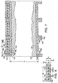
Fig. 7 is a sectional, side view of a traction sheave and a plurality of flat ropes, each having a plurality of cords. -
Fig. 8 is a sectional view of one of the flat ropes. - An elevator assembly which does not form part of the present invention is illustrated in
Figs. 1-4 for illustrative purposes only. An elevator assembly (10) includes an elevator car (12) and a guide rail assembly (14). The guide rail assembly (14) comprises an elongated, vertical member (18) having at least two faces for fixing, respectively, a first elevator car guide rail (20) and a first counterweight guide rail (22). The vertical member (18) may be attached to a stationary structure such as a wall of the hoistway (not shown). A second elevator car guide rail (16) is positioned opposite of and facing the first elevator car guide rail (20). The two elevator car guide rails (20, 16) are adapted to slidingly receive the elevator car (12) in a conventional manner through the use of conventional guide shoes (not shown) or the like. A second counterweight guide rail (24) is positioned opposite of and facing the first counterweight guide rail (22) in such a way that the two counterweight guide rails (22, 24) lay in a plane that is generally orthogonal to the plane in which the elevator car guide rails (16, 20) lay. - The counterweight-drive assembly (26) comprises a body (28) housing a drive assembly (30), a motor (32), and weights (34), as shown in
Fig.4 . Components of the drive assembly (30) are shown schematically inFig. 3 and include a toothed drive pulley (36) adapted to provide torque from the motor (32), and first and second deflection pulleys (38, 40) for effecting surface contact of the toothed belt (42) along a predetermined surface area of the drive pulley (36) for predetermined traction. A system using a toothed belt is not within the scope of the present invention. Also shown schematically inFig. 3 are tension varying devices (44, 46) which may be of a conventional type such as springs (not shown). A belt-tensioning device (48) is shown schematically and it may also be of a conventional type such as a spring (not shown). The motor (32) can be an electric motor and can be supplied power and control signals via a power and control cable (50) as shown, whereby the cable (50) is adapted to move with the counterweight-drive assembly (26). - A rope, group of ropes or suspension belt (52), as shown, suspends both the elevator car (12) and the counterweight-drive assembly (26). A first end (54) of the suspension belt (52) is fixed to a stationary object overhead, such as a beam (56) of the ceiling of the hoistway (not shown). A first idler pulley (58) fixed to the counterweight-drive assembly (26) engages the suspension belt (52). A second idler pulley (60) fixed to the overhead beam (56) engages the suspension belt (52). Third and fourth idler pulleys (62, 64) are fixed to the bottom of the elevator car (12) and also engage the belt (52). The third and fourth idler pulleys (62, 64) need not necessarily be positioned under the elevator car (12) and may be, for example, replaced by one or more idler pulleys positioned above the car. The second end (64) of the suspension belt (52) is fixed relative to the hoistway (not shown) at a height sufficient to enable desired vertical movement of the elevator car (12) and counterweight-drive asembly (26) as will be described below.
- In operation, when the motor (26) is energized, torque is transferred through the toothed drive pulley (32) to the toothed belt (42) such that the counterweight-drive assembly (26) will move along and relative to the toothed belt (42). The counterweight-drive assembly (26) will selectively move up or down depending on the direction of rotation of the toothed drive pulley (36). When the counterweight-drive assembly (26) is caused to move downward along the toothed belt (42) the first idler pulley (58) moves downward with it thereby lengthening the amount of belt (52) between the first and second idler pulleys (60). As a result, the length of available belt (52) extending past the second idler pulley (60) is proportionally shortened and the elevator car (12) is caused to be lifted upward on the third and fourth idler pulleys (62, 64). In a similar manner, the elevator car (12) is lowered as the counterweight-drive assembly (26) is driven upward.
- Referring now to
Figs. 5-6 , an embodiment of the present invention is directed to a self-climbing counterweight-drive assembly (100). The counterweight-drive assembly (100) can be adapted to be used with a suspension belt (52) and idler (58, 60, 62, 64) arrangement in accordance withFigs. 1-4 or in a similar fashion to couple the assembly (100) with an elevator car (12). As is the case of the illustrative arrangement in accordance withFigs. 1-4 , movement of the elevator car (12) will be dependent upon movement of the counterweight-drive assembly (100). - The counter-weight drive assembly (100) of the this embodiment includes a body (102) having fixed thereon a group of four electric motors (104, 106, 108, 110). Each motor (104-110) is equipped with a corresponding drive sheave (112, 114, 116, 118). A pair of fixed ropes (120, 122) are attached to an overhead structure (not shown) in the hoistway (not shown) and are either fixed or tensioned by conventional means (not shown) at the bottom. As shown specifically in
Fig. 6 with respect to the second rope (122), each rope (120, 122) extends downwardly to engage and wrap under a lower drive sheave (118), extends upwardly to engage and wrap over an upper drive sheave (114), and extends downward again to be tensioned or fixed. - The traction between the ropes (120, 122) and sheaves (112-118) is controlled by adjusting the tension in each respective rope (120, 122). In accordance with the invention the ropes (120, 122) are flat ropes because they are capable of wrapping around small diameter sheaves while supplying sufficient traction. It is then possible to minimize profile thickness of the assembly (100).
- As is the case in the arrangement in accordance with
Figs. 1-4 , traction is not dependent upon weight and, therefore a light weight elevator car (12) can be implemented. In the above-described embodiment, each drive sheave (112-118) is engaged by one of the ropes (120, 122) about 180 degrees and, thus, the total effective wrap angle is about 360 degrees on each side. The total wrap angle is determinative of the total traction. - It is conceivable to vary the above embodiment by powering only two of the four motors, or by providing one motor with transmission components to drive all four sheaves. It is further conceivable to provide only one rope instead of two.
- As can be realized from the foregoing description of the above embodiment, mounting motors on a counterweight-drive assembly (100) will remove vibration and noise from the car (12). The positioning of the drive sheaves (112-118) makes sheave mounting and servicing convenient. The ability to use small motors (104-110) provides costs savings.
- A principal feature of the present invention is the flatness of the ropes used in the above described elevator system. The increase in aspect ratio results in a rope that has an engagement surface, defined by the width dimension "w", that is optimized to distribute the rope pressure. Therefore, the maximum rope pressure is minimized within the rope. In addition, by increasing the aspect ratio relative to a round rope, which has an aspect ratio equal to one, the thickness "t1" of the flat rope (see
Fig. 8 ) may be reduced while maintaining a constant cross-sectional area of the portions of the rope supporting the tension load in the rope. - As shown in
Fig. 7 and 8 , theflat ropes 722 include a plurality of individualload carrying cords 726 encased within a common layer ofcoating 728. Thecoating layer 728 separates theindividual cords 726 and defines anengagement surface 730 for engaging thetraction sheave 724. Theload carrying cords 726 may be formed from a high-strength, lightweight non-metallic material, such as aramid fibers, or may be formed from a metallic material, such as thin, high-carbon steel fibers. It is desirable to maintain the thickness "d" of thecords 726 as small as possible in order to maximize the flexibility and minimize the stress in thecords 726. In addition, for cords formed from steel fibers, the fiber diameters should be less than .25 millimeters in diameter and preferably in the range of about .10 millimeters to .20 millimeters in diameter. Steel fibers having such diameter improve the flexibility of the cords and the rope. By incorporating cords having the weight, strength, durability and, in particular, the flexibility characteristics of such materials into the flat ropes, the traction sheave diameter "D" may be reduced while maintaining the maximum rope pressure within acceptable limits. - The
engagement surface 730 is in contact with acorresponding surface 750 of thetraction sheave 724. Thecoating layer 728 is formed from a polyurethane material, preferably a thermoplastic urethane, that is extruded onto and through the plurality ofcords 726 in such a manner that each of theindividual cords 726 is restrained against longitudinal movement relative to theother cords 726. Other materials may also be used for the coating layer if they are sufficient to meet the required functions of the coating layer: traction, wear, transmission of traction loads to the cords and resistance to environmental factors. It should be understood that although other materials may be used for the coating layer, if they do not meet or exceed the mechanical properties of a thermoplastic urethane, then the benefits resulting from the use of flat ropes may be reduced. With the thermoplastic urethane mechanical properties thetraction sheave 724 diameter is reducible to 100 millimeters or less. - As a result of the configuration of the
flat rope 722, the rope pressure may be distributed more uniformly throughout therope 722. Because of the incorporation of a plurality ofsmall cords 726 into the flat ropeelastomer coating layer 728, the pressure on eachcord 726 is significantly diminished over prior art ropes. Cord pressure is decreased at least as n-½, with n being the number of parallel cords in the flat rope, for a given load and wire cross section. Therefore, the maximum rope pressure in the flat rope is significantly reduced as compared to a conventionally roped elevator having a similar load carrying capacity. Furthermore, the effective rope diameter 'd' (measured in the bending direction) is reduced for the equivalent load bearing capacity and smaller values for the sheave diameter 'D' may be attained without a reduction in the D/d ratio. In addition, minimizing the diameter D of the sheave permits the use of less costly, more compact, high speed motors as the drive machine. - A
traction sheave 724 having atraction surface 750 configured to receive theflat rope 722 is also shown inFig. 7 . Theengagement surface 750 is complementarily shaped to provide traction and to guide the engagement between theflat ropes 722 and thesheave 724. Thetraction sheave 724 includes a pair ofrims 744 disposed on opposite sides of thesheave 724 and one ormore dividers 745 disposed between adjacent flat ropes. Thetraction sheave 724 also includesliners 742 received within the spaces between therims 744 anddividers 745. Theliners 742 define theengagement surface 750 such that there arelateral gaps 754 between the sides of theflat ropes 722 and theliners 742. The pair ofrims 744 and dividers, in conjunction with the liners, perform the function of guiding theflat ropes 722 to prevent gross alignment problems in the event of slack rope conditions, etc. Although shown as including liners, it should be noted that a traction sheave without liners may be used. - While the preferred embodiments have been herein described, it is acknowledged that variations to these embodiments can be made without departing from the scope of what is claimed.
Claims (4)
- An elevator system comprising:a suspension member (52);a drive member (120,122;722) fixed within an elevator hoistway;a counterweight-drive assembly (100) suspended by the suspension member and having drive means for drivingly engaging said drive member (120,122;722) in traction for driving said counterweight-drive assembly (100) relative thereto; andan elevator car (12) suspended by the suspension member (52) for concurrent movement of the car (12) and counterweight-drive assembly (100);whereby said elevator car (12) is moved in response to movement of said counterweight-drive assembly (100) relative to the drive member (120,122;722);
characterised in that:said drive member (120,122;722) is a flat rope. - An elevator system according to claim 1, wherein said suspension member (52) comprises a series of idler pulleys, including a first idler (58) pulley fixed to said counterweight-drive means (100), a second idler pulley (60) fixed relative to the hoistway, and at least one idler pulley (62,64) fixed to said elevator car (12).
- An elevator system as claimed in claim 1 or 2, wherein said counterweight-drive assembly (100) comprises a counterweight body (102) and
said drive means is mounted on said body (102), said drive means including at least one drive sheave (112,114,116,118) adapted to drivingly engage in traction said flat rope (120,122;722), and including motor means (104,106,108,110) for supplying torque to said at least one drive sheave (112,114,116,118) to effect movement of the counterweight body (102) relative to said flat rope (120,122;722). - An elevator system according to claim 3, wherein said drive means comprise a plurality of electric motors (104,106,108,110) and corresponding drive sheaves (112,114,116,118) mounted on said body (102).
Priority Applications (1)
| Application Number | Priority Date | Filing Date | Title |
|---|---|---|---|
| EP07008069A EP1808399B1 (en) | 1998-02-26 | 1999-02-19 | Belt-climbing elevator having drive in counterweight |
Applications Claiming Priority (7)
| Application Number | Priority Date | Filing Date | Title |
|---|---|---|---|
| US09/031,108 US6401871B2 (en) | 1998-02-26 | 1998-02-26 | Tension member for an elevator |
| US31108 | 1998-02-26 | ||
| US09/163,584 US6138799A (en) | 1998-09-30 | 1998-09-30 | Belt-climbing elevator having drive in counterweight |
| US163584 | 1998-09-30 | ||
| US218990 | 1998-12-22 | ||
| US09/218,990 US6739433B1 (en) | 1998-02-26 | 1998-12-22 | Tension member for an elevator |
| PCT/US1999/003641 WO1999043592A1 (en) | 1998-02-26 | 1999-02-19 | Belt-climbing elevator having drive in counterweight |
Related Child Applications (1)
| Application Number | Title | Priority Date | Filing Date |
|---|---|---|---|
| EP07008069A Division EP1808399B1 (en) | 1998-02-26 | 1999-02-19 | Belt-climbing elevator having drive in counterweight |
Publications (2)
| Publication Number | Publication Date |
|---|---|
| EP1056676A1 EP1056676A1 (en) | 2000-12-06 |
| EP1056676B1 true EP1056676B1 (en) | 2008-10-22 |
Family
ID=27363793
Family Applications (1)
| Application Number | Title | Priority Date | Filing Date |
|---|---|---|---|
| EP99908277A Expired - Lifetime EP1056676B1 (en) | 1998-02-26 | 1999-02-19 | Belt-climbing elevator having drive in counterweight |
Country Status (8)
| Country | Link |
|---|---|
| EP (1) | EP1056676B1 (en) |
| JP (1) | JP4380914B2 (en) |
| CN (1) | CN1299333A (en) |
| BR (1) | BR9908227A (en) |
| DE (2) | DE69939773D1 (en) |
| ES (2) | ES2315007T3 (en) |
| PT (1) | PT1056676E (en) |
| WO (1) | WO1999043592A1 (en) |
Families Citing this family (25)
| Publication number | Priority date | Publication date | Assignee | Title |
|---|---|---|---|---|
| JP3480403B2 (en) * | 1999-12-09 | 2003-12-22 | 株式会社日立製作所 | Elevator |
| US6353979B1 (en) * | 2000-01-19 | 2002-03-12 | Otis Elevator Company | Termination for flat flexible tension member |
| US6695098B1 (en) * | 2000-01-21 | 2004-02-24 | Otis Elevator Company | Self-locking wrap termination for tension member |
| DE10014002A1 (en) * | 2000-03-22 | 2001-10-04 | Hillenkoetter & Ronsieck | Vertical elevator, has drive mechanism integrated into counterweight attached to lift car traction device |
| JP2002173281A (en) * | 2000-12-11 | 2002-06-21 | Toshiba Elevator Co Ltd | Elevator |
| EP1367019B1 (en) * | 2001-02-16 | 2015-09-23 | Fujitec Co., Ltd | Both-way movable body driving mechanism and elevator device using the same |
| DE10140390B4 (en) * | 2001-08-23 | 2005-12-01 | HIRO LIFT Hillenkötter + Ronsieck GmbH | vertical lift |
| JP4927277B2 (en) * | 2001-09-28 | 2012-05-09 | 東芝エレベータ株式会社 | elevator |
| ES2251620T3 (en) | 2001-11-23 | 2006-05-01 | Inventio Ag | ELEVATOR WITH A MEANS OF TRANSMISSION IN THE FORM OF A BELT, ESPECIALLY WITH BELT OF NUNVIOS CUNEIFORMES AS A CARRIER AND / OR MOTOR. |
| JP3921603B2 (en) * | 2002-01-18 | 2007-05-30 | ニッタ株式会社 | Elevator drive belt |
| JP2004001916A (en) * | 2002-05-30 | 2004-01-08 | Otis Elevator Co | Elevator device |
| DE60217935T3 (en) * | 2002-11-25 | 2010-12-23 | Otis Elevator Co., Farmington | SCREEN ARRANGEMENT FOR AN ELEVATOR SYSTEM |
| KR100688730B1 (en) * | 2003-02-13 | 2007-03-02 | 미쓰비시덴키 가부시키가이샤 | Elevator equipment |
| CN1741950A (en) * | 2003-02-19 | 2006-03-01 | 三菱电机株式会社 | Elevator |
| ES2407981T3 (en) | 2006-06-14 | 2013-06-17 | Inventio Ag | Elevator |
| EP1867597B1 (en) * | 2006-06-14 | 2013-03-06 | Inventio AG | Lift |
| CN101472829A (en) | 2006-06-26 | 2009-07-01 | 奥蒂斯电梯公司 | Hoist installation for reducing tunnel dimension |
| EP2303750B1 (en) * | 2008-07-23 | 2013-10-09 | Inventio AG | Elevator assembly with self-driving elevator cabin |
| ES1075543Y (en) | 2011-09-07 | 2012-01-26 | Thyssenkrupp Elevator Mfg Spain S L | ELEVATOR WITH BELT AND PULLEY TOOTHED AND WITH COUNTERWEIGHT |
| CN102976191A (en) * | 2012-11-19 | 2013-03-20 | 昆山欧立电梯配件有限公司 | Steel belt elevator |
| CN104030136A (en) * | 2013-03-08 | 2014-09-10 | 黄柏森 | Double-driving elevator |
| CN103231972B (en) * | 2013-04-25 | 2016-04-20 | 江门市蒙德电气股份有限公司 | A kind of drive configuration of elevator |
| CN106044494B (en) * | 2016-07-19 | 2018-10-09 | 苏州福特美福电梯有限公司 | A kind of double drive formula emergency staircase |
| US11673773B2 (en) * | 2020-11-07 | 2023-06-13 | Otis Elevator Company | Ropeless elevator propulsion system |
| US20220194742A1 (en) * | 2020-12-21 | 2022-06-23 | Otis Elevator Company | Elevator system with a climbing counterweight |
Citations (4)
| Publication number | Priority date | Publication date | Assignee | Title |
|---|---|---|---|---|
| US3101130A (en) * | 1960-10-12 | 1963-08-20 | Silopark S A | Elevator system in which drive mechanism is mounted upon the counterweight |
| GB2134209A (en) * | 1982-12-30 | 1984-08-08 | Blacks Equip Ltd | Belts or ropes suitable for haulage and lifts |
| US5191920A (en) * | 1991-05-01 | 1993-03-09 | Mcgregor Harold R | Z-belt type lifting and stabilizing mechanism for vertical bag filling machines |
| EP0565516A1 (en) * | 1992-04-09 | 1993-10-13 | Werner Mag. Dr. Hagel | Elevator |
Family Cites Families (4)
| Publication number | Priority date | Publication date | Assignee | Title |
|---|---|---|---|---|
| DE1506479A1 (en) * | 1967-06-14 | 1969-12-18 | Hans Mangelsdorff | Elastic headstock chain drive, especially for industrial and garage lifts |
| US3878916A (en) * | 1973-02-07 | 1975-04-22 | Jr Gerome R White | Rack and pinion drive counterbalanced hoist systems |
| DE2333120A1 (en) * | 1973-06-29 | 1975-01-23 | Rudolf Dr Ing Vogel | DRIVING AND / OR REVERSING ROLLERS FOR STEEL BELTS AS A CARRIER FOR TRANSPORT MEANS |
| FI95687C (en) * | 1993-06-28 | 1996-03-11 | Kone Oy | Counterweight elevator machine / elevator motor |
-
1999
- 1999-02-19 PT PT99908277T patent/PT1056676E/en unknown
- 1999-02-19 ES ES99908277T patent/ES2315007T3/en not_active Expired - Lifetime
- 1999-02-19 BR BR9908227-6A patent/BR9908227A/en not_active IP Right Cessation
- 1999-02-19 ES ES07008069T patent/ES2336495T3/en not_active Expired - Lifetime
- 1999-02-19 EP EP99908277A patent/EP1056676B1/en not_active Expired - Lifetime
- 1999-02-19 DE DE69939773T patent/DE69939773D1/en not_active Expired - Lifetime
- 1999-02-19 WO PCT/US1999/003641 patent/WO1999043592A1/en not_active Application Discontinuation
- 1999-02-19 JP JP2000533358A patent/JP4380914B2/en not_active Expired - Fee Related
- 1999-02-19 CN CN 99805444 patent/CN1299333A/en active Pending
- 1999-02-19 DE DE69941801T patent/DE69941801D1/en not_active Expired - Lifetime
Patent Citations (4)
| Publication number | Priority date | Publication date | Assignee | Title |
|---|---|---|---|---|
| US3101130A (en) * | 1960-10-12 | 1963-08-20 | Silopark S A | Elevator system in which drive mechanism is mounted upon the counterweight |
| GB2134209A (en) * | 1982-12-30 | 1984-08-08 | Blacks Equip Ltd | Belts or ropes suitable for haulage and lifts |
| US5191920A (en) * | 1991-05-01 | 1993-03-09 | Mcgregor Harold R | Z-belt type lifting and stabilizing mechanism for vertical bag filling machines |
| EP0565516A1 (en) * | 1992-04-09 | 1993-10-13 | Werner Mag. Dr. Hagel | Elevator |
Also Published As
| Publication number | Publication date |
|---|---|
| PT1056676E (en) | 2008-12-18 |
| JP4380914B2 (en) | 2009-12-09 |
| ES2336495T3 (en) | 2010-04-13 |
| EP1056676A1 (en) | 2000-12-06 |
| CN1299333A (en) | 2001-06-13 |
| WO1999043592A1 (en) | 1999-09-02 |
| DE69939773D1 (en) | 2008-12-04 |
| JP2002504470A (en) | 2002-02-12 |
| BR9908227A (en) | 2000-10-31 |
| ES2315007T3 (en) | 2009-03-16 |
| DE69941801D1 (en) | 2010-01-21 |
Similar Documents
| Publication | Publication Date | Title |
|---|---|---|
| EP1056676B1 (en) | Belt-climbing elevator having drive in counterweight | |
| EP1056675B1 (en) | Elevator system having drive motor located between elevator car and hoistway sidewall | |
| US6193018B1 (en) | Belt-climbing elevator having drive in counterweight | |
| EP1066213B1 (en) | Elevator system with overhead drive motor | |
| CA2465031C (en) | Lift with belt-like transmission means, particularly with wedge-ribbed belt, as support means and/or drive means | |
| EP1037847B1 (en) | Elevator system with compact machineroom | |
| CN1934022B (en) | Elevator | |
| KR20010041286A (en) | Dual sheave rope climber using flat flexible ropes | |
| EP1042209B1 (en) | Elevator system having drive motor located adjacent to hoistway door | |
| WO1999043601A2 (en) | Dual sheave rope climber using flat flexible ropes | |
| EP1097101B1 (en) | Elevator system having drive motor located at the bottom portion of the hoistway | |
| WO1999043602A1 (en) | Belt-climbing elevator having drive in counterweight and common drive and suspension rope | |
| EP1808399B1 (en) | Belt-climbing elevator having drive in counterweight | |
| EP1676807B1 (en) | Elevator system with overhead drive motor | |
| EP1042211A1 (en) | Drum drive elevator using flat belt | |
| EP1911715B1 (en) | Elevator system having drive motor located at the bottom portion of the hoistway | |
| EP1604938B1 (en) | Elevator system having drive motor located adjacent to hoistway door | |
| KR20070039054A (en) | Elevator apparatus | |
| KR20010041323A (en) | Elevator system having drive motor located between elevator car and hoistway sidewall |
Legal Events
| Date | Code | Title | Description |
|---|---|---|---|
| PUAI | Public reference made under article 153(3) epc to a published international application that has entered the european phase |
Free format text: ORIGINAL CODE: 0009012 |
|
| 17P | Request for examination filed |
Effective date: 20000926 |
|
| AK | Designated contracting states |
Kind code of ref document: A1 Designated state(s): DE ES FR IT PT |
|
| 17Q | First examination report despatched |
Effective date: 20040331 |
|
| 17Q | First examination report despatched |
Effective date: 20040331 |
|
| GRAP | Despatch of communication of intention to grant a patent |
Free format text: ORIGINAL CODE: EPIDOSNIGR1 |
|
| GRAS | Grant fee paid |
Free format text: ORIGINAL CODE: EPIDOSNIGR3 |
|
| GRAA | (expected) grant |
Free format text: ORIGINAL CODE: 0009210 |
|
| AK | Designated contracting states |
Kind code of ref document: B1 Designated state(s): DE ES FR IT PT |
|
| REF | Corresponds to: |
Ref document number: 69939773 Country of ref document: DE Date of ref document: 20081204 Kind code of ref document: P |
|
| REG | Reference to a national code |
Ref country code: PT Ref legal event code: SC4A Free format text: AVAILABILITY OF NATIONAL TRANSLATION Effective date: 20081205 |
|
| REG | Reference to a national code |
Ref country code: ES Ref legal event code: FG2A Ref document number: 2315007 Country of ref document: ES Kind code of ref document: T3 |
|
| PGFP | Annual fee paid to national office [announced via postgrant information from national office to epo] |
Ref country code: PT Payment date: 20090106 Year of fee payment: 11 |
|
| PLBE | No opposition filed within time limit |
Free format text: ORIGINAL CODE: 0009261 |
|
| STAA | Information on the status of an ep patent application or granted ep patent |
Free format text: STATUS: NO OPPOSITION FILED WITHIN TIME LIMIT |
|
| PGFP | Annual fee paid to national office [announced via postgrant information from national office to epo] |
Ref country code: IT Payment date: 20090209 Year of fee payment: 11 |
|
| 26N | No opposition filed |
Effective date: 20090723 |
|
| REG | Reference to a national code |
Ref country code: PT Ref legal event code: MM4A Free format text: LAPSE DUE TO NON-PAYMENT OF FEES Effective date: 20100819 |
|
| PG25 | Lapsed in a contracting state [announced via postgrant information from national office to epo] |
Ref country code: PT Free format text: LAPSE BECAUSE OF NON-PAYMENT OF DUE FEES Effective date: 20100819 |
|
| PG25 | Lapsed in a contracting state [announced via postgrant information from national office to epo] |
Ref country code: IT Free format text: LAPSE BECAUSE OF NON-PAYMENT OF DUE FEES Effective date: 20100219 |
|
| REG | Reference to a national code |
Ref country code: FR Ref legal event code: PLFP Year of fee payment: 18 |
|
| PGFP | Annual fee paid to national office [announced via postgrant information from national office to epo] |
Ref country code: ES Payment date: 20160208 Year of fee payment: 18 |
|
| PGFP | Annual fee paid to national office [announced via postgrant information from national office to epo] |
Ref country code: FR Payment date: 20160121 Year of fee payment: 18 |
|
| PGFP | Annual fee paid to national office [announced via postgrant information from national office to epo] |
Ref country code: DE Payment date: 20170119 Year of fee payment: 19 |
|
| REG | Reference to a national code |
Ref country code: DE Ref legal event code: R082 Ref document number: 69939773 Country of ref document: DE Representative=s name: SCHMITT-NILSON SCHRAUD WAIBEL WOHLFROM PATENTA, DE |
|
| REG | Reference to a national code |
Ref country code: FR Ref legal event code: ST Effective date: 20171031 |
|
| PG25 | Lapsed in a contracting state [announced via postgrant information from national office to epo] |
Ref country code: FR Free format text: LAPSE BECAUSE OF NON-PAYMENT OF DUE FEES Effective date: 20170228 |
|
| REG | Reference to a national code |
Ref country code: ES Ref legal event code: FD2A Effective date: 20180625 |
|
| PG25 | Lapsed in a contracting state [announced via postgrant information from national office to epo] |
Ref country code: ES Free format text: LAPSE BECAUSE OF NON-PAYMENT OF DUE FEES Effective date: 20170220 |
|
| REG | Reference to a national code |
Ref country code: DE Ref legal event code: R119 Ref document number: 69939773 Country of ref document: DE |
|
| PG25 | Lapsed in a contracting state [announced via postgrant information from national office to epo] |
Ref country code: DE Free format text: LAPSE BECAUSE OF NON-PAYMENT OF DUE FEES Effective date: 20180901 |