EP1056510B1 - Dispositif medical implantable a couplage rf, dote d'une source d'alimentation de secours rechargeable - Google Patents
Dispositif medical implantable a couplage rf, dote d'une source d'alimentation de secours rechargeable Download PDFInfo
- Publication number
- EP1056510B1 EP1056510B1 EP98907507A EP98907507A EP1056510B1 EP 1056510 B1 EP1056510 B1 EP 1056510B1 EP 98907507 A EP98907507 A EP 98907507A EP 98907507 A EP98907507 A EP 98907507A EP 1056510 B1 EP1056510 B1 EP 1056510B1
- Authority
- EP
- European Patent Office
- Prior art keywords
- energy
- transmitting
- transmitting unit
- receiving unit
- rechargeable
- Prior art date
- Legal status (The legal status is an assumption and is not a legal conclusion. Google has not performed a legal analysis and makes no representation as to the accuracy of the status listed.)
- Expired - Lifetime
Links
Images


Classifications
-
- A—HUMAN NECESSITIES
- A61—MEDICAL OR VETERINARY SCIENCE; HYGIENE
- A61N—ELECTROTHERAPY; MAGNETOTHERAPY; RADIATION THERAPY; ULTRASOUND THERAPY
- A61N1/00—Electrotherapy; Circuits therefor
- A61N1/18—Applying electric currents by contact electrodes
- A61N1/32—Applying electric currents by contact electrodes alternating or intermittent currents
- A61N1/36—Applying electric currents by contact electrodes alternating or intermittent currents for stimulation
- A61N1/372—Arrangements in connection with the implantation of stimulators
- A61N1/378—Electrical supply
- A61N1/3787—Electrical supply from an external energy source
Definitions
- the present invention relates to an implantable medical device including a rechargeable back-up power source and a charging unit for recharging the back-up power source via RF coupling.
- implantable, electrically operated medical devices are: cardiac pacemakers which restore a sick human heart to a normal rhythm, neural simulators which control nerve or brain response (such as pain or epileptic seizures), infusion pumps for subcutaneously drug delivery (such as insulin pump), and diagnostic devices for monitoring a patient's condition.
- a system with the features of the first part of claim 1 is known from DE-A-196 17 102.
- an RF coupled implantable medical system comprising: a transmitting unit; a receiving unit including an implantable, electrically operated, medical device; the transmitting unit including RF energy transmitting circuitry, RF signal receiving circuitry and first control circuitry coupled to the RF energy transmitting circuitry and to said RF signal receiving circuitry for controlling the amount of RF energy transmitted to the receiving unit; the receiving unit including RF energy receiving circuitry, RF signal transmitting circuitry, a rechargeable power supply coupled to the RF energy receiving circuitry and second control circuitry for adjusting the charging current flowing into the rechargeable battery coupled to the rechargeable power supply, to the RF energy receiving circuitry, to the RF signal transmitting circuitry and to the implanted medical device; and mode selection circuitry for setting the transmitting unit to operate in one of the following modes: 1) "RF only", 2) "battery only” or (3) "combination of both".
- circuitry can be provided in the receiving unit for measuring the charge level of the rechargeable battery and, upon sensing a fully charged battery, automatically up-linking a coded signal which commands the transmitting unit to "stop" transmitting RF energy.
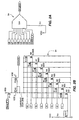
- FIG. 1 a block electrical schematic circuit diagram of an implantable, rechargeable tissue stimulator system 10.
- the system 10 includes a transmitter 12 and a receiver 14, the latter being surgically implanted beneath a patient's skin 16.
- the receiver 14 is connected, via lead connector 18, to an implanted medical device, which in this embodiment, is an implanted lead 19 which contains, at it's distal end 20, stimulating electrodes 21-24.
- These electrodes 21-24 are implanted adjacent to the target tissue to be stimulated (i.e., a specific nerve or a nerve bundle, a specific area of the brain or a specific muscle within the human body).
- the implanted receiver 14 receives therapy values, transmitted by the transmitter 12 via RF signals, which are decoded by decoder 25 and then stored in a non-volatile memory (EPROM) 27.
- EPROM non-volatile memory
- the major components of the transmitter 12 are a micro controller 26 which is used, via software, to: 1) control the output of a programmable DC to DC converter 28 in order to regulate the amount of RF energy to be coupled into the receiver 14; 2) read data and command inputs inputted via a keyboard 30, display messages and menus via a display 32, transmit therapy parameter values, via a programming encoder 34, a transmit driver 36 and an antenna 38, to the implanted receiver 14; 3) and receive commands and patient's diagnostic data, transmitted from the implanted receiver 14, via the antenna 38, an amplifier 39 and a decoder 40.
- the transmitter 12 when the transmitter 12 is powered up via a switch 41 and a "start therapy” key 42 on the keyboard 30 is pressed, the transmitter 12 will transmit the "start” command to the receiver 14 which will initiate delivery of therapy by the receiver 14. Likewise, if a "stop therapy” key 43 on the keyboard 30 is pressed, the transmitter 12 will transmit the "stop” command to the receiver 14 which will cease delivery of therapy.
- the implanted receiver 14 of FIG. 1 can be programmed by the physician or patient to obtain it's operating power from one of three sources: 1) RF coupled energy only; 2) back-up rechargeable power supply/source 44 only; or 3) a combination of both whereby the implanted receiver 14 alternates automatically from one to the other according to a preset schedule programmed via the transmitter 12.
- the system 10 will automatically switch the source of VDD to the output of the voltage regulator 54 (line conductor 50) when the transmitter 12 is proximal to the receiver 14, or to the rechargeable power source 44 when the transmitter 12 is removed away from the receiver 14.
- the automatic switching is performed by the micro controller 46 in response to the state of line conductor 50 which is at +3.0 volts when RF energy is being coupled into an inductor 60 (the transmitter 12 is proximal to the receiver 14) or is 0 volts in the absence of RF energy (the transmitter 12 is away from the receiver 14).
- the receiver 14 When the receiver 14 is programmed to "battery only” power acquisition mode, it's exclusive source of operating power becomes the rechargeable power source 44. After prolonged use, the rechargeable power source 44 will reach a near depleted level, at which point the receiver 14 will transmit, via an RF communication link 61, a "recharge” command to the transmitter 12. This will cause the transmitter 12 to generate, via the battery 62, the DC/DC converter 28 and an output inductor 64, high energy RF waves which are coupled into the inductor 60 contained within the receiver 14.
- the actual level of RF energy generated by the inductor 64 is regulated by an output port 70 of the micro controller 26 as a real-time response to data transmitted by the receiver 14 via the micro controller 46, the data representing the voltage level E1 at the output of the rectifier 74 in the receiver 14 which is measured via an attenuator 76 and an analog to digital converter 78.
- This feedback system extends the life of the battery 62 within the transmitter 12, by adjusting, as a function of distance between the inductors 64 and 60, the RF energy required to quickly recharge the rechargeable power source 44. A close proximity requires much less RF energy to recharge the rechargeable power source 44 than a longer distance would, in the same time.
- the micro controller 46 regulates, as a function of temperature, the current level used to recharge the rechargeable power source 44.
- the temperature is measured by a thermistor 80 which is adhered to the rechargeable power source 44 during manufacturing.
- the junction between the thermistor 80 and a resistor 82 form a voltage divider which is fed through an analog switch 84 to an analog to digital converter 86 and, via a line conductor 88, to the micro controller 46.
- the ohmic value of the thermistor 80 drops proportionally to the temperature, thus reducing the voltage at the line conductor 88 to the micro controller 46.
- This loop forms a temperature-controlled, current-regulated charging system which restricts the temperature rise of the rechargeable power source 44 during recharging, thus preventing the power source 44 from suffering electrolyte starvation and gas generation. Both of these phenomena will, if left unchecked, dramatically reduce the reliability and service life of the power source 44. Also, during recharging of the power source 44, the micro controller 46 will monitor the voltage level of the power source 44 via a line conductor 90, analog switch 92, the A/D converter 86 and, finally, the line conductor 88.
- the micro controller 46 Upon sensing a fully charged state, the micro controller 46 will telemeter to transmitter 12, via the RF communications link 61, a "stop" recharging command and simultaneously will turn off a D/A converter 94 which will cut off the current needed to charge the rechargeable power source 44. In this manner, the power source 44 cannot be overcharged, even if the "stop" command was not received by the transmitter 12 due to electromagnetic interference.
- the receiver 14 when the receiver 14 is programmed to "RF only", the power acquisition mode, it's exclusive source of operating power is the low level RF energy generated by transmitter 12 and coupled into the inductor 60 within the receiver 14.
- the actual level of RF energy generated by the inductor 64 is regulated by the output port 70 of the micro controller 26 to the minimum level required to operate the receiver 14 and the rechargeable power source 44 is trickle charged, as a real-time response to data transmitted by the receiver 14 via the micro controller 26, i.e., the data representing the voltage level E1 at the output of the rectifier 74 which is measured via the attenuator 76 and the analog to digital converter 78.
- This feedback system extends the life of the battery 62 within the transmitter 12, by adjusting the RF energy required to operate the receiver 14 and maintain a trickle charge to the rechargeable power source 44, as a function of the distance between the inductors 64 and 60. At close proximity, much less RF energy is required to accomplish these functions than at a longer distance.
- the micro controller 46 regulates, as a function of temperature, the current level used to trickle charge the power source 46, by the same method already explained in the previous paragraph. Again, this prevents electrolyte starvation and gas generation within the rechargeable power source 44. Also, during trickle charging, the micro controller 46 will monitor the charge level of the power source 44, and upon sensing a fully charged state, the receiver 14 will telemeter to the transmitter 12 the "stop" recharging command and simultaneously will turn off the D/A converter 94 which will cut off the current needed to charge the power source 44. In this manner, the power source 44 cannot be overcharged, even if the "stop" command was not received by the transmitter 12 due to electromagnetic interference.
- the micro controller 46 When the receiver 14 is programmed to "combination" power acquisition mode, the micro controller 46 will automatically switch delivery of operating power to the receiver 14 to RF coupled energy upon detection of RF induced voltage at E1. Likewise, the micro controller 46 will switch delivery of operating power to the rechargeable power source 44 upon loss of RF induced voltage at E1. The patient may select, via a menu shown in the transmitter's display 32, fast or trickle charge to the rechargeable power source 44.
- the micro controller 46 Upon sensing that the charge in the rechargeable power source 44 is below a predetermined level, the micro controller 46 signals the patient, via an audible alarm 96 and/or a vibrating alarm 98, that the rechargeable power source 44 should be recharged.
- the D/A converter 94 is software programmable, precision current source whose output is regulated by the micro controller 46. It should be noted that this type of D/A converter is best implemented into an integrated circuit where the electrical characteristics of the transistors can be precisely matched.
- resistor R1 is used to set the base bias current for the converter 94.
- Transistors N17 and N1 form a 1:1 current mirror where the current into the transistor N17 equals the current through the transistor N1, since both transistors have equal channel width and length.
- the channel width for the transistors N2 through N8 are binary weighted, so that the transistor N2 has twice the width of the transistors N1, N3 has twice the width of N2, and so forth. This binary scaling results in transistor N2 conducting twice the current of transistor N1 (assuming equal bias current), the transistor N3 conducting twice the current of the transistor N2, and so forth.
- the transistors N9 through N16 are used as pass devices to allow the current available at the transistor N1 through the transistor N8 to pass to the current sum line 1.
- the on-off state for the transistors N9 through N16 is governed by inputs i1 through i8 which, in one embodiment, are output ports from the micro controller 46 (bus line 100 in FIG. 1). In this manner, the micro controller 46 is able to select any value of current between 1 and 256 times that of the current flowing through the resistor R1 (bias current) to pass to the current sum line 1.
- Input line "enable.n” is used to turn on and off the D/A converter.
- the transistor P1 conducts connecting VDD to the sources of the transistors P2 and P3 which form a 1:1 current mirror. Therefore, the current source by the transistor P3 equals the current flowing through the transistors P2, P3 being the output current device ("iSOURCE") for this D/A converter 94.
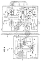
- FIG. 3 is shown a block diagram for an implantable, rechargeable drug delivery system.
- the block diagram for the transmitter 12 is the same as for the transmitter 12 shown in FIG. 1.
- the block diagram for the receiver 14 contains the same power supply system, supply switching means and method for recharging the rechargeable power source 44 that has been already described above in connection with the description of FIG. 1, but has been modified to incorporate the components required to assemble an implantable drug delivery system.
- a drug reservoir 104 which contains the drug to be delivered by the receiver 14
- a refill septum 106 used to percutaneously, via a hypodermic needle, refill the drug reservoir 104
- a portioning pump 108 used to dispense a precise volume of drug to a catheter 110 by making one or more small injections (portions)
- the wire conductors 121-123 are used to drive the pump 108 and the wire conductors 131-133 are used to sense when a portion has been delivered.
- the micro controller 46 measures the time required for delivering each drug portion, and based on this time determines if the pump 108 is empty or contains fluid, since the former condition results is a faster time than the latter.
- the micro controller 46 Upon sensing a "pump empty" condition, the micro controller 46 signals the patient, via an audible alarm 140 and/or a vibrating alarm 142, that the reservoir 104 is empty.
- the titanium housing 150 of the receiver 14 should be in close proximity to the audible alarm 140 in order to transmit the sound waves to outside the human body.
- FIG. 4 is a block diagram of an implantable, rechargeable cardiac pacemaker system.
- the block diagram for the transmitter 12 is the same as for the block diagram of the transmitter 12 shown in FIG. 1.
- the block diagram for the receiver 14 contains the same power supply system, supply switching means and method for recharging the rechargeable power source 44 that already have been described above in connection with the description of FIG. 1, but has been modified to incorporate the components required to assemble an implantable, rechargeable cardiac pacemaker system.
- a pulse amplitude D/A converter 202 which is used to regulate, under command of the micro controller 46, the amplitude of the stimulating pulses delivered to the human heart
- a bus 204 which carries the binary value for the amplitude from the micro controller 46 to the D/A converter 202
- an amplifier and filter 206 which detects and amplifies the cardiac depolarization waves (such as R or P waves) and filters out other signal frequencies not related to cardiac activity
- an implanted lead 210 containing electrodes 211-212 which is used to deliver stimulating pulses to the heart in order to regulate the heart's rhythm, but which is used also to pick-up and carry the cardiac depolarization waves to the amplifier/filter 206.
- These cardiac waves are used by the micro controller 46 to measure the intrinsic rate of the heart. The measurement is utilized to determine if electrical stimulation pulses are needed to speed-up the heart.
- the micro controller 46 Upon sensing that the charge in the rechargeable power source 44 is below a predetermined level, the micro controller 46 signals the patient, via an audible alarm 220 and/or a vibrating alarm 222, that the rechargeable power source 44 should be recharged.
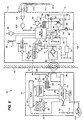
- FIG. 5 is illustrated a block diagram of an implantable, rechargeable cardioverter/defibrillator.
- the block diagram for the transmitter 12 is the same as the block diagram for the transmitter 12 shown in FIG. 1.
- the block diagram for the receiver 14 contains the same power supply system, supply switching means and method for recharging the rechargeable power source 44 that already have been described above in connection with the description of FIG. 1, but has been modified to incorporate the components required to assemble an implantable, rechargeable cardioverter/defibrillator system.
- a high voltage output, DC to DC converter 302 used to convert the low voltage available at the rechargeable power source 44 to a relatively higher voltage required to cardiovert a fibrillating human heart
- a bus 304 which carries the binary value for the voltage amplitude from the micro controller 46 to the D/A converter 302
- an amplifier/filter 306 used to detect the presence of a cardiac arrhythmia such as fibrillation or tachycardia
- the DC/DC converter 302 is used to generate either low voltage pulses to pace the human heart when needed or high voltage pulses to shock a large number of cardiac cells into synchrony, thereby restoring a normal cardiac rhythm.
- the micro controller 46 via the bus 304, regulates the timing and amplitude of low voltage pulses or high voltage shocks, depending if an arrhythmia is detected or not.
- the micro controller 46 Upon sensing that the charge in the rechargeable power source 44 is below a predetermined level, the micro controller 46 signals the patient, via an audible alarm 320 and/or a vibrating alarm 322, that the rechargeable power source 44 should be recharged.
- FIG. 6 there is illustrated a block diagram of an implantable, rechargeable monitor and diagnostic system.
- the block diagram for the transmitter 12 is the same as the block diagram for the transmitter 12 shown in FIG. 1.
- the block diagram for the receiver 14 contains the same power supply system, supply switching means and method for recharging the rechargeable power source 44 that already have been described in connection with the description of FIG. 1, but has been modified to incorporate the components required to assemble an implantable, rechargeable monitor and diagnostic system. These components are: 1) an amplifier/filter 406 used to amplify the desired biological signals and to filter out other undesirable signals; 2) an analog to digital converter 408 which is used to convert the biological signal into a digital value representative of frequency and amplitude of the biological signal; 3) a monitoring lead 410 containing electrodes 411-412 which are used to pick-up and carry the biological signals to the amplifier/filter 406.
- the mission of the monitor and diagnostic system shown in FIG. 6 is to monitor and record, in a non-volatile memory 414, specific biological signals and events occurring adjacent to the monitoring electrodes 411-412. Later, at a convenient time, these recordings can be telemetered to the transmitter 12 which will produce, via a graphic recorder 416, a hard copy of the biological signals for the physician's examination and eventual diagnosis. Any time biological signals occur, they are scrutinized by the micro controller 46 for specific morphology which would cause the event to be stored into the memory 27 for later examination by the physician.
- An example of a typical use would be to record dysfunctional endocardiac signals which, when inspected by a trained physician, may reveal the origin of a cardiac dysfunction not detected by conventional means, such as a surface EKG.
Claims (14)
- Système médical implantable à couplage RF (10) comprenant :une unité d'émission (12) ;une unité de réception (14) incluant un dispositif médical implantable à commande électrique ;la dite unité d'émission incluant des moyens d'émission d'énergie RF (64), des moyens de réception de signal RF (38) et des premier moyens de commande (26) couplés aux dits moyens d'émission d'énergie RF et aux dits moyens de réception de signal RF pour régler la quantité d'énergie RF envoyée à la dite unité de réception ;la dite unité de réception incluant des moyens de réception d'énergie RF (60), des moyens d'émission de signal RF, une alimentation en énergie rechargeable (44) couplée aux dits moyens de réception d'énergie RF, et des deuxièmes moyens de commande (46) pour régler le courant de charge introduit dans la dite pile rechargeable couplés à la dite alimentation en énergie rechargeable, aux dits moyens de réception d'énergie RF, aux dits moyens d'émission de signal RF et au dit dispositif médical implanté ; etdes moyens de sélection de mode pour établir la dite unité d'émission pour un fonctionnement dans un des modes suivants : 1) « RF seulement », 2) « pile seulement » ou 3) « combinaison des deux ».
- Système selon la revendication 1, dans lequel la dite unité de réception, lorsque la dite unité d'émission est établie pour fonctionner dans le dit mode « RF seulement », peut fonctionner de manière à fournir une énergie électrique au dit dispositif implantable, pourvu que la dite unité d'émission soit proche de la dite unité de réception et que la dite unité de réception détecte l'énergie RF transmise.
- Système selon la revendication 1, dans lequel la dite unité de réception, lorsque la dite unité d'émission est établie de manière à fonctionner dans le dit mode « pile seulement », peut fonctionner périodiquement pour fournir une énergie électrique au dit dispositif implantable à partir de la dite alimentation en énergie rechargeable pendant une période d'au moins 24 heures.
- Système selon la revendication 1, dans lequel les dits moyens d'émission d'énergie RF de la dite unité d'émission comprennent des moyens de sélection de mode pour recharger la dite pile rechargeable à un débit « rapide » ou à un débit de « maintien ».
- Système selon la revendication 1, dans lequel la dite unité de réception, lorsque la dite unité d'émission est établie de manière à fonctionner dans le dit mode de « combinaison », peut fonctionner pour fournir une énergie électrique au dit dispositif implantable, par l'intermédiaire d'un redresseur, directement au dit dispositif médical implanté, pourvu que la dite unité d'émission soit proche de la dite unité de réception et, d'autre part, pour fournir une « charge de maintien » à la dite alimentation en énergie rechargeable.
- Système selon la revendication 1, dans lequel la dite unité de réception comprend en outre des moyens pour mesurer le niveau de charge de la dite pile rechargeable et, lors de la détection d'une pile complètement chargée, pour renvoyer automatiquement un signal codé qui ordonne à la dite unité d'émission de « cesser » la transmission d'énergie RF.
- Système selon la revendication 1, dans lequel la dite unité de réception comprend un boítier en titane contenant les dits moyens de réception d'énergie RF, les dits moyens d'émission de signal RF, la dite pile rechargeable et les dits deuxièmes moyens de commande.
- Système selon la revendication 1, dans lequel les dits moyens d'émission d'énergie RF de la dite unité d'émission sont construits de façon à émettre une énergie à une fréquence aussi basse que 10 Hz et jusqu'à 20 000 Hz au moins.
- Système selon la revendication 1, dans lequel la dite pile rechargeable comporte un capteur de température qui est monté de façon étroitement adjacente à la dite pile et qui est couplé via les dits moyens d'émission de signal RF aux dits premiers moyens de commande de la dite unité d'émission, de sorte que le niveau de l'énergie RF transmise peut être réduit proportionnellement à la réduction du débit de charge de la pile rechargeable dans la dite unité de réception, afin de réduire la consommation d'énergie à partir d'une source d'énergie alimentant la dite unité d'émission.
- Système selon la revendication 1, dans lequel les dits premiers moyens de commande de la dite unité d'émission comprennent des moyens de réglage du niveau de transfert d'énergie RF de l'unité d'émission à l'unité de réception en fonction d'un ou plusieurs des paramètres suivants : (a) le niveau de charge de la dite pile rechargeable, (b) le débit de charge choisi, et (c) l'alimentation en énergie sélectionnée pour la dite unité de réception.
- Système selon la revendication 1, dans lequel la dite unité d'émission comprend un affichage visuel couplé aux dits premiers moyens de commande.
- Système selon la revendication 1, dans lequel la dite unité d'émission comprend un clavier couplé aux dits premiers moyens de commande, comportant des touches pour démarrer et arrêter la recharge de la dite pile rechargeable dans le dispositif médical implantable.
- Système selon la revendication 1, dans lequel la dite unité d'émission comprend une pile, de sorte que la dite unité d'émission est portable et ne dépend pas d'une source d'énergie en courant alternatif.
- Système selon la revendication 1, dans lequel le dit dispositif médical implantable est choisi dans le groupe comprenant un stimulateur de tissu, un système d'administration de médicament, un système de stimulateur cardiaque et un régulateur / défibrillateur cardiaque.
Applications Claiming Priority (1)
| Application Number | Priority Date | Filing Date | Title |
|---|---|---|---|
| PCT/US1998/003105 WO1999042173A1 (fr) | 1998-02-23 | 1998-02-23 | Dispositif medical implantable a couplage rf, dote d'une source d'alimentation de secours rechargeable |
Publications (3)
| Publication Number | Publication Date |
|---|---|
| EP1056510A1 EP1056510A1 (fr) | 2000-12-06 |
| EP1056510A4 EP1056510A4 (fr) | 2001-08-29 |
| EP1056510B1 true EP1056510B1 (fr) | 2005-05-11 |
Family
ID=22266410
Family Applications (1)
| Application Number | Title | Priority Date | Filing Date |
|---|---|---|---|
| EP98907507A Expired - Lifetime EP1056510B1 (fr) | 1998-02-23 | 1998-02-23 | Dispositif medical implantable a couplage rf, dote d'une source d'alimentation de secours rechargeable |
Country Status (3)
| Country | Link |
|---|---|
| EP (1) | EP1056510B1 (fr) |
| DE (1) | DE69830203T2 (fr) |
| WO (1) | WO1999042173A1 (fr) |
Families Citing this family (26)
| Publication number | Priority date | Publication date | Assignee | Title |
|---|---|---|---|---|
| US7177690B2 (en) | 1999-07-27 | 2007-02-13 | Advanced Bionics Corporation | Implantable system having rechargeable battery indicator |
| US6516227B1 (en) | 1999-07-27 | 2003-02-04 | Advanced Bionics Corporation | Rechargeable spinal cord stimulator system |
| US7225032B2 (en) | 2003-10-02 | 2007-05-29 | Medtronic Inc. | External power source, charger and system for an implantable medical device having thermal characteristics and method therefore |
| US20050075696A1 (en) | 2003-10-02 | 2005-04-07 | Medtronic, Inc. | Inductively rechargeable external energy source, charger, system and method for a transcutaneous inductive charger for an implantable medical device |
| DE10353943B4 (de) | 2003-11-18 | 2013-01-03 | Deutsches Zentrum für Luft- und Raumfahrt e.V. | Anordnung zur drahtlosen Energieübertragung an eine implantierte Einrichtung |
| US7505816B2 (en) | 2005-04-29 | 2009-03-17 | Medtronic, Inc. | Actively cooled external energy source, external charger, system of transcutaneous energy transfer, system of transcutaneous charging and method therefore |
| US7744523B2 (en) * | 2007-06-07 | 2010-06-29 | Emory University | Drive circuit for magnetic stimulation |
| DE102008005059A1 (de) | 2008-01-18 | 2009-07-23 | Giesecke & Devrient Gmbh | Vorrichtung zum Ansteuern eines Aktuators |
| US8214042B2 (en) | 2009-05-26 | 2012-07-03 | Boston Scientific Neuromodulation Corporation | Techniques for controlling charging of batteries in an external charger and an implantable medical device |
| AU2014232252B2 (en) | 2013-03-15 | 2018-01-18 | Alfred E. Mann Foundation For Scientific Research | Current sensing multiple output current stimulators with fast turn on time |
| WO2015017475A2 (fr) | 2013-07-29 | 2015-02-05 | Alfred E. Mann Foundation For Scientific Research | Circuit d'attaque de classe e commandé par microprocesseur |
| CA2958199C (fr) | 2014-08-15 | 2023-03-07 | Axonics Modulation Technologies, Inc. | Positionnement d'une derivation electromyographique et titrage de la stimulation dans un systeme de stimulation nerveuse pour le traitement de la vessie hyperactive |
| US9855423B2 (en) | 2014-08-15 | 2018-01-02 | Axonics Modulation Technologies, Inc. | Systems and methods for neurostimulation electrode configurations based on neural localization |
| CA2957962C (fr) | 2014-08-15 | 2018-05-01 | Axonics Modulation Technologies, Inc. | Structure de fixation de sonde implantable pour la stimulation des nerfs afin d'attenuer un dysfonctionnement de la vessie et d'autres indications |
| EP3180075A4 (fr) | 2014-08-15 | 2018-03-07 | Axonics Modulation Technologies Inc. | Programmateur clinicien électromyographique intégré destiné à être utilisé avec un neurostimulateur implantable |
| AU2015301489B2 (en) | 2014-08-15 | 2020-01-23 | Axonics Modulation Technologies, Inc. | External pulse generator device and associated methods for trial nerve stimulation |
| JP6751718B2 (ja) | 2015-01-09 | 2020-09-09 | アクソニクス モジュレーション テクノロジーズ インコーポレイテッド | 神経刺激充電デバイスとの使用のための取り付けデバイスおよび関連方法 |
| CN107427675B (zh) | 2015-01-09 | 2021-10-26 | 艾克索尼克斯股份有限公司 | 患者遥控器及其与神经刺激系统一起使用的相关联方法 |
| ES2729702T3 (es) | 2015-01-09 | 2019-11-05 | Axonics Modulation Tech Inc | Antena mejorada y procedimientos de uso para un estimulador nervioso implantable |
| JP6946261B2 (ja) | 2015-07-10 | 2021-10-06 | アクソニクス インコーポレイテッド | Asicを用いない内部電子機器を有する埋め込み可能神経刺激装置および方法 |
| JP6876363B2 (ja) | 2016-01-29 | 2021-05-26 | アクソニクス モジュレーション テクノロジーズ インコーポレイテッド | 埋込可能な神経刺激器の充電を最適化する周波数調製のための方法およびシステム |
| AU2017218157B2 (en) | 2016-02-12 | 2022-09-29 | Axonics, Inc. | External pulse generator device and associated methods for trial nerve stimulation |
| EP3755418B1 (fr) | 2018-02-22 | 2023-06-21 | Axonics, Inc. | Fils de neurostimulation pour stimulation nerveuse d'essai |
| WO2020185902A1 (fr) | 2019-03-11 | 2020-09-17 | Axonics Modulation Technologies, Inc. | Dispositif de charge doté de bobine décentrée |
| US11439829B2 (en) | 2019-05-24 | 2022-09-13 | Axonics, Inc. | Clinician programmer methods and systems for maintaining target operating temperatures |
| US11848090B2 (en) | 2019-05-24 | 2023-12-19 | Axonics, Inc. | Trainer for a neurostimulator programmer and associated methods of use with a neurostimulation system |
Family Cites Families (13)
| Publication number | Priority date | Publication date | Assignee | Title |
|---|---|---|---|---|
| US3195540A (en) * | 1963-03-29 | 1965-07-20 | Louis C Waller | Power supply for body implanted instruments |
| US4134408A (en) * | 1976-11-12 | 1979-01-16 | Research Corporation | Cardiac pacer energy conservation system |
| US4408607A (en) | 1981-04-13 | 1983-10-11 | Empi, Inc. | Capacitive energy source and circuitry for powering medical apparatus |
| US4793353A (en) | 1981-06-30 | 1988-12-27 | Borkan William N | Non-invasive multiprogrammable tissue stimulator and method |
| US4441498A (en) | 1982-05-10 | 1984-04-10 | Cardio-Pace Medical, Inc. | Planar receiver antenna coil for programmable electromedical pulse generator |
| DE4104359A1 (de) | 1991-02-13 | 1992-08-20 | Implex Gmbh | Ladesystem fuer implantierbare hoerhilfen und tinnitus-maskierer |
| US5314453A (en) | 1991-12-06 | 1994-05-24 | Spinal Cord Society | Position sensitive power transfer antenna |
| US5314457A (en) | 1993-04-08 | 1994-05-24 | Jeutter Dean C | Regenerative electrical |
| US5383912A (en) | 1993-05-05 | 1995-01-24 | Intermedics, Inc. | Apparatus for high speed data communication between an external medical device and an implantable medical device |
| US5411537A (en) * | 1993-10-29 | 1995-05-02 | Intermedics, Inc. | Rechargeable biomedical battery powered devices with recharging and control system therefor |
| US5476488A (en) | 1993-12-15 | 1995-12-19 | Pacesetter, Inc. | Telemetry system power control for implantable medical devices |
| DE19617102A1 (de) * | 1996-04-19 | 1997-10-23 | Michael Dr Klausing | Verfahren zur elektronischen Energieeinspeisung |
| US5713939A (en) * | 1996-09-16 | 1998-02-03 | Sulzer Intermedics Inc. | Data communication system for control of transcutaneous energy transmission to an implantable medical device |
-
1998
- 1998-02-23 WO PCT/US1998/003105 patent/WO1999042173A1/fr active IP Right Grant
- 1998-02-23 EP EP98907507A patent/EP1056510B1/fr not_active Expired - Lifetime
- 1998-02-23 DE DE69830203T patent/DE69830203T2/de not_active Expired - Lifetime
Also Published As
| Publication number | Publication date |
|---|---|
| WO1999042173A1 (fr) | 1999-08-26 |
| DE69830203D1 (de) | 2005-06-16 |
| DE69830203T2 (de) | 2006-01-12 |
| EP1056510A4 (fr) | 2001-08-29 |
| EP1056510A1 (fr) | 2000-12-06 |
Similar Documents
| Publication | Publication Date | Title |
|---|---|---|
| EP1056510B1 (fr) | Dispositif medical implantable a couplage rf, dote d'une source d'alimentation de secours rechargeable | |
| US5733313A (en) | RF coupled, implantable medical device with rechargeable back-up power source | |
| US4793353A (en) | Non-invasive multiprogrammable tissue stimulator and method | |
| US4612934A (en) | Non-invasive multiprogrammable tissue stimulator | |
| US5735887A (en) | Closed-loop, RF-coupled implanted medical device | |
| US6381496B1 (en) | Parameter context switching for an implanted device | |
| US9907957B2 (en) | Patient programmer for implantable devices | |
| US5769877A (en) | High value capacitive, replenishable power source | |
| US7813801B2 (en) | Implantable medical device powered by rechargeable battery | |
| US7493174B2 (en) | Implantable medical lead | |
| EP2752221B1 (fr) | Système de stimulateur de moelle épinière rechargeable | |
| US6516227B1 (en) | Rechargeable spinal cord stimulator system | |
| US5941906A (en) | Implantable, modular tissue stimulator | |
| US7515967B2 (en) | Ambulatory energy transfer system for an implantable medical device and method therefore | |
| US7493159B2 (en) | Trial neuro stimulator with lead diagnostics | |
| US6400988B1 (en) | Implantable cardiac device having precision RRT indication | |
| US8024047B2 (en) | Alignment indication for transcutaneous energy transfer | |
| US8265770B2 (en) | Driver circuitry switchable between energy transfer and telemetry for an implantable medical device | |
| EP0191404A1 (fr) | Palpeur de l'activité pour la commande des stimulateurs cardiaques | |
| US20100076524A1 (en) | Inductively rechargeable external energy source, charger, system and method for a transcutaneous inductive charger for an implantable medical device | |
| US20030065366A1 (en) | System and method for determining remaining battery life for an implantable medical device | |
| US20100249882A1 (en) | Acoustic Telemetry System for Communication with an Implantable Medical Device | |
| US5735880A (en) | Method and apparatus for reliably producing pacing pulse trains | |
| US20220409907A1 (en) | Hibernation of electronics in an implantable stimulator |
Legal Events
| Date | Code | Title | Description |
|---|---|---|---|
| PUAI | Public reference made under article 153(3) epc to a published international application that has entered the european phase |
Free format text: ORIGINAL CODE: 0009012 |
|
| 17P | Request for examination filed |
Effective date: 20000913 |
|
| AK | Designated contracting states |
Kind code of ref document: A1 Designated state(s): CH DE ES FR GB IE IT LI |
|
| RAP1 | Party data changed (applicant data changed or rights of an application transferred) |
Owner name: MEDTRONIC AVE INC. |
|
| RAP1 | Party data changed (applicant data changed or rights of an application transferred) |
Owner name: MEDTRONIC INC. |
|
| A4 | Supplementary search report drawn up and despatched |
Effective date: 20010712 |
|
| AK | Designated contracting states |
Kind code of ref document: A4 Designated state(s): CH DE ES FR GB IE IT LI |
|
| RIC1 | Information provided on ipc code assigned before grant |
Free format text: 7A 61N 1/08 A, 7A 61N 1/378 B |
|
| RAP1 | Party data changed (applicant data changed or rights of an application transferred) |
Owner name: MEDTRONIC INC. |
|
| RAP1 | Party data changed (applicant data changed or rights of an application transferred) |
Owner name: MEDTRONIC, INC. |
|
| GRAP | Despatch of communication of intention to grant a patent |
Free format text: ORIGINAL CODE: EPIDOSNIGR1 |
|
| GRAS | Grant fee paid |
Free format text: ORIGINAL CODE: EPIDOSNIGR3 |
|
| GRAA | (expected) grant |
Free format text: ORIGINAL CODE: 0009210 |
|
| AK | Designated contracting states |
Kind code of ref document: B1 Designated state(s): CH DE ES FR GB IE IT LI |
|
| PG25 | Lapsed in a contracting state [announced via postgrant information from national office to epo] |
Ref country code: LI Free format text: LAPSE BECAUSE OF FAILURE TO SUBMIT A TRANSLATION OF THE DESCRIPTION OR TO PAY THE FEE WITHIN THE PRESCRIBED TIME-LIMIT Effective date: 20050511 Ref country code: IT Free format text: LAPSE BECAUSE OF FAILURE TO SUBMIT A TRANSLATION OF THE DESCRIPTION OR TO PAY THE FEE WITHIN THE PRESCRIBED TIME-LIMIT;WARNING: LAPSES OF ITALIAN PATENTS WITH EFFECTIVE DATE BEFORE 2007 MAY HAVE OCCURRED AT ANY TIME BEFORE 2007. THE CORRECT EFFECTIVE DATE MAY BE DIFFERENT FROM THE ONE RECORDED. Effective date: 20050511 Ref country code: CH Free format text: LAPSE BECAUSE OF FAILURE TO SUBMIT A TRANSLATION OF THE DESCRIPTION OR TO PAY THE FEE WITHIN THE PRESCRIBED TIME-LIMIT Effective date: 20050511 |
|
| REG | Reference to a national code |
Ref country code: GB Ref legal event code: FG4D |
|
| REG | Reference to a national code |
Ref country code: CH Ref legal event code: EP |
|
| REG | Reference to a national code |
Ref country code: IE Ref legal event code: FG4D |
|
| REF | Corresponds to: |
Ref document number: 69830203 Country of ref document: DE Date of ref document: 20050616 Kind code of ref document: P |
|
| PG25 | Lapsed in a contracting state [announced via postgrant information from national office to epo] |
Ref country code: ES Free format text: LAPSE BECAUSE OF FAILURE TO SUBMIT A TRANSLATION OF THE DESCRIPTION OR TO PAY THE FEE WITHIN THE PRESCRIBED TIME-LIMIT Effective date: 20050822 |
|
| REG | Reference to a national code |
Ref country code: CH Ref legal event code: PL |
|
| PG25 | Lapsed in a contracting state [announced via postgrant information from national office to epo] |
Ref country code: IE Free format text: LAPSE BECAUSE OF NON-PAYMENT OF DUE FEES Effective date: 20060223 Ref country code: GB Free format text: LAPSE BECAUSE OF NON-PAYMENT OF DUE FEES Effective date: 20060223 |
|
| ET | Fr: translation filed | ||
| PLBE | No opposition filed within time limit |
Free format text: ORIGINAL CODE: 0009261 |
|
| STAA | Information on the status of an ep patent application or granted ep patent |
Free format text: STATUS: NO OPPOSITION FILED WITHIN TIME LIMIT |
|
| 26N | No opposition filed |
Effective date: 20060214 |
|
| GBPC | Gb: european patent ceased through non-payment of renewal fee |
Effective date: 20060223 |
|
| REG | Reference to a national code |
Ref country code: IE Ref legal event code: MM4A |
|
| PGFP | Annual fee paid to national office [announced via postgrant information from national office to epo] |
Ref country code: FR Payment date: 20100222 Year of fee payment: 13 |
|
| PGFP | Annual fee paid to national office [announced via postgrant information from national office to epo] |
Ref country code: DE Payment date: 20100226 Year of fee payment: 13 |
|
| REG | Reference to a national code |
Ref country code: FR Ref legal event code: ST Effective date: 20111102 |
|
| REG | Reference to a national code |
Ref country code: DE Ref legal event code: R119 Ref document number: 69830203 Country of ref document: DE Effective date: 20110901 |
|
| PG25 | Lapsed in a contracting state [announced via postgrant information from national office to epo] |
Ref country code: FR Free format text: LAPSE BECAUSE OF NON-PAYMENT OF DUE FEES Effective date: 20110228 |
|
| PG25 | Lapsed in a contracting state [announced via postgrant information from national office to epo] |
Ref country code: DE Free format text: LAPSE BECAUSE OF NON-PAYMENT OF DUE FEES Effective date: 20110901 |