EP1056426B1 - Vial transferset and method - Google Patents
Vial transferset and method Download PDFInfo
- Publication number
- EP1056426B1 EP1056426B1 EP99908450A EP99908450A EP1056426B1 EP 1056426 B1 EP1056426 B1 EP 1056426B1 EP 99908450 A EP99908450 A EP 99908450A EP 99908450 A EP99908450 A EP 99908450A EP 1056426 B1 EP1056426 B1 EP 1056426B1
- Authority
- EP
- European Patent Office
- Prior art keywords
- vial
- tubular
- stopper
- piercing
- transfer member
- Prior art date
- Legal status (The legal status is an assumption and is not a legal conclusion. Google has not performed a legal analysis and makes no representation as to the accuracy of the status listed.)
- Expired - Lifetime
Links
Images

Classifications
-
- A—HUMAN NECESSITIES
- A61—MEDICAL OR VETERINARY SCIENCE; HYGIENE
- A61J—CONTAINERS SPECIALLY ADAPTED FOR MEDICAL OR PHARMACEUTICAL PURPOSES; DEVICES OR METHODS SPECIALLY ADAPTED FOR BRINGING PHARMACEUTICAL PRODUCTS INTO PARTICULAR PHYSICAL OR ADMINISTERING FORMS; DEVICES FOR ADMINISTERING FOOD OR MEDICINES ORALLY; BABY COMFORTERS; DEVICES FOR RECEIVING SPITTLE
- A61J1/00—Containers specially adapted for medical or pharmaceutical purposes
- A61J1/14—Details; Accessories therefor
- A61J1/20—Arrangements for transferring or mixing fluids, e.g. from vial to syringe
- A61J1/2096—Combination of a vial and a syringe for transferring or mixing their contents
-
- A—HUMAN NECESSITIES
- A61—MEDICAL OR VETERINARY SCIENCE; HYGIENE
- A61J—CONTAINERS SPECIALLY ADAPTED FOR MEDICAL OR PHARMACEUTICAL PURPOSES; DEVICES OR METHODS SPECIALLY ADAPTED FOR BRINGING PHARMACEUTICAL PRODUCTS INTO PARTICULAR PHYSICAL OR ADMINISTERING FORMS; DEVICES FOR ADMINISTERING FOOD OR MEDICINES ORALLY; BABY COMFORTERS; DEVICES FOR RECEIVING SPITTLE
- A61J1/00—Containers specially adapted for medical or pharmaceutical purposes
- A61J1/14—Details; Accessories therefor
- A61J1/1412—Containers with closing means, e.g. caps
-
- A—HUMAN NECESSITIES
- A61—MEDICAL OR VETERINARY SCIENCE; HYGIENE
- A61J—CONTAINERS SPECIALLY ADAPTED FOR MEDICAL OR PHARMACEUTICAL PURPOSES; DEVICES OR METHODS SPECIALLY ADAPTED FOR BRINGING PHARMACEUTICAL PRODUCTS INTO PARTICULAR PHYSICAL OR ADMINISTERING FORMS; DEVICES FOR ADMINISTERING FOOD OR MEDICINES ORALLY; BABY COMFORTERS; DEVICES FOR RECEIVING SPITTLE
- A61J1/00—Containers specially adapted for medical or pharmaceutical purposes
- A61J1/14—Details; Accessories therefor
- A61J1/20—Arrangements for transferring or mixing fluids, e.g. from vial to syringe
- A61J1/2003—Accessories used in combination with means for transfer or mixing of fluids, e.g. for activating fluid flow, separating fluids, filtering fluid or venting
- A61J1/2006—Piercing means
- A61J1/201—Piercing means having one piercing end
Definitions
- This invention relates to an improved vial connector assembly or transferset, a method of affixing a transferset to a vial and a method of establishing fluid communication between a vial and syringe, IV set or the like which permits the use of a conventional or standard vial and syringe or the like to transfer fluid from a syringe to a vial or withdraw liquid medicament, for example, from a vial to a syringe.
- the improved transferset and method of this invention results in improved aspiration or reaspiration of a vial and improved sealing of the communication between a vial and a syringe.
- a conventional vial includes an open end, a rim surrounding the open end and a reduced diameter neck portion adjacent the rim.
- the vial is conventionally sealed with an elastomeric stopper which includes a portion inserted into the neck of the vial and a planar rim portion which overlies the vial rim.
- the stopper is normally secured to the vial rim with an aluminum collar or cap.
- the aluminum collar includes a tubular portion which surrounds the rim portions of the stopper and vial, an inwardly projecting annular portion which overlies the rim portion of the stopper and a distal portion which is crimped into the vial neck beneath the vial rim portion. Because aluminum is malleable, the collar accommodates the buildup of tolerances of the dimensions of the stopper and vial rim.
- the dimensions and tolerances of standard vials and stoppers are set by the International Standards Organization (ISO).
- a powdered drug is generally reconstituted by inserting the needle of a syringe through the pierceable stopper on the vial and injecting a diluent, such as water, or a solvent into the vial.
- a diluent such as water
- the reconstituted drug is then reaspirated from the vial with the same or a different syringe after mixing the diluent or solvent with the dry drug.
- this method exposes the healthcare worker to being pricked by the needle of the syringe and contamination of the needle or the drug.
- the prior art has therefore proposed various fluid or liquid transfer assemblies which may be secured to a vial under sterile conditions and which may then utilized to transfer liquid, such as a diluent or solvent, from a syringe to a vial and reconstituted medicament from the vial to a syringe which prevent contamination of the liquid medicament.
- the assembly is protected from contamination by a cap or cover which is removed only prior to use.
- the transfer assembly includes a needle which pierces the stopper of the vial and the liquid is transferred through the needle lumen as disclosed, for example, in U.S. Patent No. 5,429,256.
- the conventional vial stopper is eliminated in favor of a fluid transfer assembly having a rubber stopper which is inserted into the neck of the vial without a planar rim portion.
- the stopper remains within the vial until such time as reconstitution of the drug is required.
- the transfer assembly is actuated, the stopper is urged toward the interior of the vial to open the neck, thereby permitting fluid flow through the transfer assembly into the vial body.
- Examples of such embodiments include the MONOVIAL® line of drug delivery devices manufactured and sold by Becton Dickinson Pharmaceutical Systems of Le Pont de Claix, France and exemplified by U.S. Patent No. 5,358,501.
- this embodiment is an excellent drug reconstitution system having superior properties, particularly convenience of use and maintenance of the sterile conditions of the drug in the vial, particularly where the vial is of a relatively large size, typically twelve milliliters or more, pharmaceutical companies have expressed an interest in an approach where the vial may also be a smaller size.
- US-A-3 977 555 relates to a protective safety cap for a medicament vial having a tubular extension and a needle structure adapted to pierce the stopper of the vial held therein.
- the needle structure extends beyond the tubular extension.
- the needle structure is surrounded by a closed cover which is slideably attached at the outer surface of the tubular extension.
- the cover is pressed down thereby driving the needle structure through the stopper. Then the cover is removed and a syringe is attached to the needle structure to extract the medicament contained in the vial.
- US-A-5 358 501 discloses a storage bottle containing a constituent of a medical solution and a transfer device for transferring the solution into a container.
- An elongate element in form of a needle is placed inside the transfer device, wherein the tip is directed away from the bottle and the blunt end is located inside the transfer device.
- the elongate element comprises two longitudinal channels for establishing communication between the bottle and the container.
- the bottle is closed by an elastomeric plug which is removed by the blunt end of the elongate element when it is driven with its tip into the stopper of the container.
- the needle must therefore be withdrawn during aspiration of the vial or reaspiration where the medicament is reconstituted in the vial following delivery of a diluent or solvent to the vial.
- liquid medicament remains in the vial because the only liquid communication with the syringe is through the needle lumen. This may be a problem particularly where the vial is relatively small. For example, assuming a twenty millimeter long needle which pierces a two to three millimeter thick stopper, if the needle is pushed all the way through the stopper, there may be distance of as much as seventeen millimeters between the needle opening and the inner surface of the stopper. This amount below the needle lumen will not be reaspirated unless the needle is substantially withdrawn.
- the vial transferset or fluid transfer assembly of this invention is adapted to establish fluid communication between a syringe, intravenous (IV) device or the like and a sealed vial.
- the syringe and vial may be conventional and manufactured according to ISO standards.
- a conventional vial as presently used by the pharmaceutical companies includes an open end, a rim surrounding the open end and a reduced diameter neck portion adjacent the rim.
- the vial is sealed with a pierceable resilient stopper generally formed of an elastomeric material and most commonly includes a portion which is inserted into the neck of the vial and a planar rim portion which is received over the vial rim.
- the central portion of the planar rim portion which overlies the opening through the neck portion of the vial generally has a thickness of about two to three millimeters and the portion of the stopper which is received in the neck portion of the vial is generally tubular having an external diameter which is slightly greater than the internal diameter of the vial neck portion to assure a secure seal.
- the transferset or transfer assembly of this invention includes a generally tubular transfer member having an open proximate end which is sealingly supported on the stopper rim portion for example in general coaxial alignment with the vial open end and an opened distal end adapted to receive a syringe or the like in sealed communication.
- a component such as the tubular transfer member is the end closest to the planar rim portion of the stopper and the distal end is the end furthest from the rim portion of the stopper.
- these terms are used solely to simplify the explanation of the invention and are not intended to define structure.
- the transferset of this invention further includes a piercing member which is received within the tubular transfer member and reciprocally supported within the tubular transfer member by an internal surface of the tubular transfer member.
- the piercing member includes a distal end and an opposed relatively sharp preferably pointed piercing proximate end opposite the stopper rim portion adapted to pierce the stopper when the syringe is driven against the distal end of the piercing member.
- the tubular transfer member provides fluid communication between the vial and a syringe, although the vial transferset of this invention may also be used to transfer fluid or liquid from a vial to another container, such as a second vial or an intravenous set.
- the piercing member includes at least one external generally longitudinal channel or groove rather than an internal lumen, thereby eliminating the problems associated with a conventional needle.
- the channel may take various forms and may include an internal channel, in the most preferred embodiment the channel is an external channel which extends generally longitudinally along at least a portion of the piercing member.
- the external channel in the piercing member extends generally longitudinally along the piercing member, but may extend spirally around the piercing member or include external and internal channels or multiple channels.
- the external channel in the piercing member provides full fluid or liquid communication between the vial and the tubular transfer member.
- the tubular transfer member when the tubular transfer member is sealingly connected to a syringe, IV or the like, the tubular transfer member then provides fluid communication between the vial and the syringe.
- the preferred embodiment of the tubular transfer member then includes an annular or circular projecting sealing lip which is biased against the planar rim portion of the stopper assuring sealed communication between the vial and the tubular transfer member.
- the sealing lip includes a relatively sharp edge which bites into the resilient stopper.
- the sealing lip of the tubular transfer member is preferably biased against the rim portion of the stopper sufficiently to stretch or prestress the rim portion of the stopper which overlies the vial opening.
- the preferred embodiment of the transferset of this invention further includes a cup-shaped cap which encloses the assembly and maintains the sterility of the transferset assembly.
- the cup-shaped cap preferably includes a radial rim portion adjacent an open end of the cup-shaped cap which preferably sealingly engages the stopper rim portion, a tubular portion surrounding the tubular transfer member and a closed distal end enclosing the distal ends of the tubular transfer member and the piercing member.
- the cap may include a separate cover portion which is integral or separate from the remainder of the cap, in the most preferred embodiment, the cap is integrally formed, such that the distal end portion may be removed prior to use.
- the tubular portion of the cap spaced from the rim portion includes a radial groove or grooves which weaken the tubular wall forming a frangible connection.
- the distal end of the cap portion may then be removed simply by twisting the distal end of the cap, thereby breaking the frangible connection.
- the transfer assembly is secured to the vial by a generally tubular collar having a radially inwardly projecting portion or annular portion which is received over the cap radial rim portion, a tubular portion surrounding the cap radial rim portion and the vial rim and a distal radial rim portion which is received in the vial neck beneath the rim portion of the vial permanently securing the transfer assembly to the vial.
- the collar is formed of a malleable material such aluminum and the radial distal portion of the collar is then crimped into the neck portion of the vial beneath the vial rim portion.
- the collar of the transferset of this invention thus replaces the aluminum collar of a conventional vial and stopper assembly and easily accommodates the dimensional tolerances of the vial and stopper assembly.
- the vial is conventionally formed of glass or plastic.
- the planar radial rim portion of the vial stopper is preferably stretched and prestressed over the open end of the vial during assembly of the transferset on the vial.
- the proximate end of the tubular transfer member includes a projecting sealing lip having a diameter less than the internal diameter of the vial open end.
- the sealing lip has a relatively sharp edge which may also bite into the resilient stopper.
- the piercing member is reciprocally supported by an internal surface of the tubular transfer member, such that the piercing member can move toward the stopper to pierce the stopper, but the piercing member is prevented from moving away from the stopper and the relatively sharp piercing proximate end of the piercing member extends beyond the proximate end of the tubular transfer member.
- the piercing end of the piercing member Upon assembly of the transferset on the vial, the piercing end of the piercing member then deforms and, in one disclosed embodiment, partially penetrates the planar rim portion of the stopper which is preferably stretched and prestressed over the vial opening by the sealing lip of the tubular transfer member, as described above.
- the piercing end of the piercing member is slightly rounded and the external channel does not extend through the proximate end, such that the relatively sharp piercing end does not initially penetrate the rim portion of the stopper, but stretches the stopper as described. This embodiment strengthens the piercing end.
- the tubular transfer member includes an internal diameter adjacent its distal end which is smaller than the internal diameter adjacent its proximate end and the piercing member includes a radial lip having a diameter greater than the smaller internal diameter of the tubular transfer member adjacent its distal end.
- the tubular transfer member has a larger counter bore adjacent its proximate end.
- the piercing member is thus free to move telescopically in the tubular transfer member toward the stopper, but prevented from moving away from the stopper.
- the piercing member has a reduced diameter portion adjacent its proximate end and a pointed piercing end further reducing the force required to drive the piercing member through the planar rim portion of the stopper.
- the most preferred embodiment of the transferset of this invention further includes a second seal surrounding the seal provided by the sealing lip of the tubular transfer member.
- the second seal is provided by an annular or circular lip which projects from the radial rim portion of the cap.
- the radial rim portion of the cap includes at least one relatively sharp sealing lip which bites into the planar rim portion of the stopper providing an improved seal which maintains the sterile condition of the content of the transferset and prevents contamination.
- the transferset of this invention may be affixed on a conventional vial and stopper assembly by the pharmaceutical companies under sterile conditions when the vial is filled and the transferset of this invention prevents contamination of the contents of the vial.
- the cap of the transferset seals the transfer assembly and the collar permanently secures the assembly on the vial, particularly where a malleable collar is utilized.
- the radially inwardly projecting or annular lip portion of the collar is preferably compressed against the radial rim portion of the cap as the distal end of the collar is crimped into the reduced diameter neck portion of the vial beneath the vial rim during assembly.
- the piercing end of the piercing member is also partially driven into the prestressed rim portion of the stopper overlying the open end of the vial, reducing the stroke required to drive the piercing member through the rim portion of the stopper as described above.
- the transferset of this invention may be utilized to transfer fluid from a vial to a syringe or IV set or any container; however, the disclosed embodiment of the transferset is specifically adapted to transfer liquid from a vial to a syringe or IV set or from a syringe or IV set to a vial.
- the distal end of the tubular transfer member includes a connector adapted to connect the tubular transfer member to a syringe to establish fluid communication between the tubular transfer member and the interior of a syringe, such as a Luer lock or Luer connector.
- a conventional syringe includes a tubular portion, a plunger having a head or fluid piston reciprocally mounted in sealed relation within the tubular portion and a reduced diameter tubular nozzle portion opposite the plunger head.
- the inside diameter of the tubular transfer member of the transferset is preferably greater than the outside diameter of the tubular nozzle portion of the syringe and the outside diameter of the syringe nozzle portion is generally approximately equal to the diameter of the distal end of the piercing member.
- the syringe nozzle portion may be telescopically received within the distal end of the tubular transfer member, wherein it is driven against the distal end of the piercing member.
- the reduced diameter nozzle portion is generally recessed within the tubular portion of the syringe, such that the proximate end of the syringe tubular portion surrounds the nozzle portion forming a tubular collar.
- the proximate end of the tubular collar includes a connector, such as a female Luer lock.
- the distal end of the tubular transfer member includes a male Luer lock connector adapted to mate with the female Luer lock of the syringe.
- the method of transferring fluid or liquid medicament from the vial to a syringe or other container then includes first connecting the connector on the syringe to the connector on the distal end of the tubular transfer member which drives the reduced diameter nozzle portion of the syringe into the distal open end of the tubular transfer member and the free end of the syringe nozzle portion is then driven against the distal end of the piercing member, driving the piercing end of the piercing member through the planar rim portion of the stopper.
- the method includes connecting the syringe to the distal end of the tubular transfer member, establishing fluid communication between the syringe through the nozzle portion and driving the piercing end of the piercing member through the rim portion of the stopper. Fluid communication is thus established between the inside of the vial and the syringe through the tubular transfer member.
- the method further includes a first step of removing the cover portion of a cap to provide access to the tubular transfer member and the piercing member.
- a radial groove is provided in the tubular portion of the cap spaced from the radial portion of the cap providing a frangible connection, such that the cover portion can be removed from the rim portion of the cap simply by twisting the distal end of the cap, breaking the frangible connection and permitting removal of the cover portion which includes the distal end of the tubular portion of the cap the closed end.
- the transferset and vial assembly is now ready for use.
- this communication is established through the external generally longitudinal channel in the piercing member.
- the channel in the piercing member extends from adjacent the piercing end to at least the enlarged portion of the piercing member and most preferably through at least an extended portion of the length of the piercing member.
- the connector on the syringe is most preferably a threaded connection, such as a Luer lock.
- this threaded connection has several turns whereby the proximate end of the piercing member is driven completely through the planar rim portion of the stopper by threading the threaded connection of the syringe on the distal end of the tubular transfer member.
- the proximate end of the piercing member is driven through the stopper by fluid pressure from the syringe.
- the elongated piercing member is inserted into the tubular transfer member, wherein the internal surface of the tubular transfer member telescopically supports the piercing member.
- the tubular transfer member includes an enlarged counterbore adjacent its proximate end and the piercing member includes a radial lip as described, the distal end of the piercing member is inserted through the proximate end of the tubular transfer member and the relatively sharp piercing end of the piercing member extends beyond the proximate end of the tubular transfer member. Then the distal end of the tubular transfer member is inserted into the open proximate end of the cup-shaped cap.
- the proximate end of the tubular transfer member includes a radial lip portion which is received within a counterbore of the radial rim portion of the cap, fixing the tubular transfer member in the cap, such that the projecting sealing lip of the tubular transfer member engages the planar rim of the stopper as described.
- the piercing member is preferably releasably retained in the tubular transfer member, such that the components of the transferset and the collar may be preassembled and delivered in bulk to a pharmaceutical company, for example, for sterile assembly on vials. Finally, the assembled piercing member, tubular transfer member and cap are assembled on the vial and affixed by the collar.
- the collar is most preferably formed of a malleable material such as aluminum and the radial rim portion of the collar is compressed against the rim portion of the cap as the distal end of the generally tubular cap is crimped into the reduced diameter neck portion of the vial beneath the vial rim.
- the compression of the radial rim portion of the collar against the rim portion of the cap compresses the resilient planar rim portion of the stopper, compressing the sealing lips into the rim portion of the stopper, stretching and pre-stressing the central portion of the planar rim portion of the stopper, assuring sealed communication between the vial and the tubular transfer member.
- this invention further includes driving the piercing end of the piercing member simultaneously into the planar radial rim of the stopper, deforming and may partially penetrate the stopper radial rim to reduce the stroke required to drive the piercing member through the stopper.
- the piercing member in the transferset of this invention has several important advantages over the prior art.
- the longitudinal channel may be a V-shaped channel for example which extends the entire length of the piercing member.
- Such a channel is easier to manufacture than a needle having very small lumen as presently used.
- a piercing member having an external channel assures complete aspiration or reaspiration of the vial without requiring partial withdrawal of the needle which exposes the healthcare worker to being pricked by the needle (if inadvertently fully withdrawn) and contamination of the liquid medicament.
- the external channel provides full communication of the liquid content of the vial, whereas a needle with a lumen requires substantial withdrawal of the needle from the vial to provide full communication through the stopper as described above. Fluid communication between the syringe and the vial is then provided by the tubular transfer member rather than the needle in the transferset of this invention.
- the described piercing member provides several important advantages in the transferset of this invention/over the prior art.
- the transferset of this invention may be utilized to reconstitute dry or powdered drugs into liquid form with an appropriate diluent or solvent solution prior to administration to a patient.
- the syringe may contain a solvent solution or diluent which is injected into the vial through the tubular transfer member and the external channel of the piercing member by depressing the plunger head of the syringe.
- the reconstituted drug or medicament may then be reaspirated from the vial to the same syringe by withdrawing the plunger head for administration to a patient.
- the healthcare worker is never exposed to a needle during this operation and the piercing member remains with the transferset and vial assembly because it is never connected to the syringe.
- the tubular transfer member is then removed from the syringe and replaced with a needle for application of the liquid medicament to a patient or connected directly to an IV line.
- tubular and tubular portion are used herein to connote a generally tubular shape.
- the disclosed embodiments are generally cylindrical tubes which are more convenient to manufacture, the tubular portions may be of any convenient shape, including polygonal.
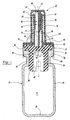
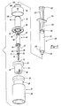
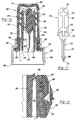
- the fluid transfer assembly or transferset 20 of this invention is adapted for establishing fluid communication with a conventional sealed vial 22 as shown in Figure 1.
- the vial includes a side wall portion 24, a bottom wall portion 26, a reduced diameter neck portion 28 and a rim portion 30.
- the vial is conventionally formed of glass or plastic and includes an interior 32 for receipt for example of a dry or liquid medicament, such as a dry vaccine 33.
- the vial is sealed with an elastomeric stopper 34 which includes a tubular portion 36 and a planar rim portion 38.
- the tubular portion 36 of the stopper preferably has an external diameter slightly greater than the internal diameter 44 of the open end of the vial and, as will be understood by those skilled in the art, the end of the tubular portion may include axial slots 40 in order to perform freeze drying of liquid in the vial.
- the vial may also include a gas, for example, to protect the liquid content of the vial, and thus the transferset of this invention is referred to as a fluid, rather than liquid transferset.
- the central portion 42 of the planar rim portion 38 is flexible and thus may be resiliently biased into the tubular portion 36, prestressing the central portion 42 as described below.
- the transferset 20 of this invention preferably includes four components, including a tubular transfer member 46, a central piercing member 48 which is reciprocally supported in the tubular transfer member, a cup-shaped cap 50 which encloses and seals the assembly and a collar member 52 which secures the transferset to the vial as shown in Figure 1.
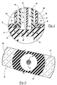
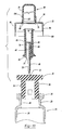
- the proximate end of the tubular transfer member 46 includes a circular or annular sealing lip 54 as shown in Figures 1 and 2, which preferably includes a sharp distal edge 56 as shown in Figure 2.
- the proximate end of the tubular transfer member 46 may include a plurality of sealing lips, such as the concentric sealing lips 86 of the cap 50 described below.
- the proximate end of the tubular transfer member 46 further includes a radial connector portion 58 as shown in Figure 2 which is described more fully hereinbelow.
- a connector such as a Luer lock 60, is provided adjacent the open distal end 62 of the tubular transfer member.
- the internal surface of the tubular transfer member 46 includes a first smaller preferably conical diameter 64 adjacent the distal end 62 and a second larger generally cylindrical diameter 66 or counterbore adjacent the proximate end.
- the distal end 67 of the piercing member 48 includes a generally cylindrical barrel portion 68 having an external diameter generally equal to or slightly less than the internal diameter 64 of the tubular transfer member 46, such that the piercing member is telescopically supported in the tubular transfer member 46 for movement toward the stopper 34 as described below.
- the piercing portion 70 adjacent the proximate end of the piercing member 48 may also be generally cylindrical and preferably has a diameter substantially less than the diameter of the barrel portion 68.
- the portion 73 of the piercing member between the radial rib 75 and the barrel portion 68 is conical.
- the proximate end of the piercing member 48 includes a relatively sharp, preferably pointed piercing end 72 and the piercing member 48 includes an external generally longitudinal channel 74 which provides communication between the interior 32 of the vial and the interior of the tubular transfer member 46 as described below.
- the piercing member 48 further includes a radial rib 75 which has a diameter greater than the inside diameter 64 of the tubular transfer member 46 adjacent its distal end and slightly smaller than the inside diameter 66 of the counter-bore, such that the piercing member 48 can move toward the planar radial rim portion 38 of the stopper for piercing of the stopper, but cannot move away from the stopper as shown in Figure 1.
- the sharp piercing end 72 of the piercing member 48 is thus retained in the tubular transfer member 46, such that the relatively sharp piercing end portion 72 of the piercing member deforms the central portion 42 of the stopper and may partially penetrate the stopper as shown, thereby reducing the stroke required to drive the piercing member through the stopper as described below.
- the cap 50 includes a tubular portion 76 which surrounds the tubular transfer member 46 preferably is spaced relation, a radial rim portion 78 at its proximate end and a closed distal end portion 80 which encloses the distal ends of the tubular transfer member 62 and the piercing member 67.
- the cap 50 is thus generally described as "cup-shaped"; however, the cap may have an open distal end which is closed by a separate removable closure, for example, such that the combination is cup-shaped.
- the tubular portion 76 of the cap includes a radial v-shaped external groove 82, such that the proximate end of the tubular portion 76 is retained to the distal portion by a relatively thin frangible connection 84 as shown in Figure 2.
- the groove 82 in the disclosed embodiment of the tubular portion 76 of the cap 50 is in the external surface as shown; however the groove may also be formed in the internal surface forming a frangible connection adjacent the external surface.
- the groove 82 may also be continuous as shown or interrupted.
- the cover portion may be connected to the remainder of the cap by spaced frangible connector portions. As described below, the distal portion of the cap or cover portion may then be removed by twisting the distal end of the cap for connection of the transferset to a syringe or the like.
- the radial rim portion 78 includes annular or preferably circular concentric sealing lips 86 which surround the sealing lip 54 of the tubular transfer member.
- the circular lips 86 on the radial portion 78 of the cap surround the sealing lip 54 on the tubular transfer member, providing a safety seal primarily to maintain sterility inside the cap 50 prior to use, thereby extending the shelf life of the product.
- the disclosed embodiment includes two concentric sealing lips 86 on the cap, it will be understood that one sealing lip may be utilized or a plurality of nonconcentric lips.
- the sealing lips 86 preferably have a relatively sharp edge and are V-shaped, such that the lips 86 bite into the resilient planar rim portion 38 of the stopper.
- the disclosed embodiment of the cap 50 further includes an outer longitudinal rim portion 88 having an inside diameter generally equal to or slightly smaller than the outside diameter of the planar rim portion 38 of the stopper as shown in Figure 1, such that the transferset 20 is accurately located on the stopper 34 and the rim portion 30 of the vial 22 with the tubular transfer member 46 generally coaxially aligned with the opening 44 through the neck portion 28 of the vial.
- the piercing member 48 is supported in the tubular transfer member 46 with its longitudinal axis X coincident with the longitudinal axis of the vial and stopper. It may be desirable, however, in certain applications to provide a nonconcentric arrangement and thus the present invention is not limited to the concentric arrangement shown.
- the tubular transfer member 46 is accurately located and supported within the cap 50 by a radial rim 90 on the radial connector portion 58 as shown in Figure 2, which is received in a recess 92 in the cap.
- the cap further includes a V-shaped radially inwardly projecting rib 93, which is received in or snapped into a V-shaped groove 94 in the tubular transfer member as shown in Figure 2, providing accurate secure location of the tubular transfer member 46 in the cap 50.
- the V-shaped interlock further permits preassembly of the tubular transfer member 46 and piercing member 48 in the cap 50 for bulk supply of the transferset and collar 52 to pharmaceutical companies, for example, for attachment to a vial, following filling of the vial with medicament, using the collar 52.
- the tubular transfer member is retained in the cap 350 for bulk supply by an interlocking rib and depression on opposed surfaces of the tubular transfer member and the cap, preferably spaced inwardly or proximately from the frangible connection.
- the piercing member is releasably retained in the tubular transfer member for bulk assembly and supply to the applicator responsible for filling the container or vial 22.
- the piercing member 48 includes a small ramped radial rib 73, spaced distally from the radial rib 75, which provides an interference fit with the internal surface 64 of the tubular transfer member 46 as best shown in Figures 5, 6, 9 and 10. This interference fit releasably retains the piercing member 48 in the tubular transfer member 46 upon assembly of the piercing member in the tubular transfer member.
- the components of the transferset 20 are retained as an assembly for bulk sale and use as described.
- the collar 52 is most preferably formed of a malleable material such as aluminum to accommodate the thickness tolerances of the stopper 34 and the rim portion 30 of the vial.
- the collar 52 includes a tubular portion 96 which surrounds the radial and longitudinal rim portions 78 and 88 of the cap 50, the planar radial rim portion 38 of the stopper and the rim portion 30 of the vial, a radially inwardly projecting portion 98 which overlies the radial rim portion 78 of the cap and a distal radial portion 100 which in the preferred embodiment is crimped into the reduced diameter neck 28 of the vial beneath the vial rim 30.
- the collar 52 further includes a distal tubular portion 102 which surrounds the proximate end of the tubular portion 76 of the cap and the radial V-shaped external groove 82 as shown in Figure 2.
- This tubular portion 102 reduces the likelihood of accidental removal of the distal portion of the cap 50 and the distal end of the tubular portion 102 includes a rounded bead 104 which prevents the healthcare worker from engaging a sharp metal edge when removing the distal end of the cap during use.
- the distal removable portion of the cap is referred to hereinafter as the cover portion.
- the cover portion may be threaded onto the proximate end of the tubular portion 76 of the cap or connected by a "living hinge.”
- the preferred embodiment of the cap 50 having a frangible connection 84 as shown in Figures 1 and 2 reduces the cost of the cap of the transferset and assures maintenance of the sterile conditions prior to use.
- the method of assembling the transferset on a vial is best shown in Figures 9 and 10.
- the distal end 67 of the piercing member 48 is inserted into the proximate end of the tubular transfer member 46.
- the barrel portion 68 of the piercing member is first received in the larger internal diameter 66, wherein the radial rib 75 is generally equal to the diameter of the internal surface 66.
- the barrel portion 68 of the piercing member is then received in the smaller diameter surface 64 until the radial rib 75 engages the radial surface 65 between the internal surfaces 66 and 64 ( Figure 10) as shown in Figure 1.
- the distal ends 62 of the tubular transfer member and 67 of the piercing member are then received in the open proximate end of the cap 50 and the tubular portion 76 of the cap 50 is then received over the tubular portion 102 of the collar and the assembly is received over the radial planar rim portion 38 of the stopper 34 and the rim portion of the vial 22.
- the tubular transfer member 46 is accurately aligned within and supported by the cap 50.
- the radial rib 90 of the tubular transfer member is received within the radial groove 92 of the cap 50 and the V-shaped rib 93 on the cap snaps into the mating V-shaped groove 94 in the tubular transfer member.
- the outer longitudinal rim 88 on the cap is received over the radial planar portion 38 of the stopper, such that the entire transferset assembly is accurately aligned on the stopper 34.
- the piercing member 48 is accurately aligned and supported within the tubular transfer member 46, such that the relatively sharp piercing end 72 extends beyond the proximate end of the tubular transfer member 46 and the piercing member 48 is able to move toward the stopper, but is restrained from withdrawing from the stopper by the radial rib 75.
- the distal open end 100 of the tubular portion 96 is initially coincident with the tubular portion 76 as shown in phantom in Figure 1. Upon assembly, however, the end 100 is deformed or crimped into the neck portion 28 of the vial beneath the rim portion 30, permanently securing the transferset 20 on the vial 22.
- the radial rim portion 78 of the cap 50 is simultaneously compressed against the planar rim portion 38 of the resilient stopper as the distal end 100 of the collar 52 is crimped, such that the piercing end 72 of the piercing member 48 is pressed into the central portion 42 of the stopper, which causes the piercing end 72 to resiliently deform the unsupported central portion 42 of the stopper and, in the embodiment disclosed in Figures 1 to 4, the piercing end 72 may partially penetrate the central portion 42 of the stopper as shown in Figure 2.
- the piercing end 72 of the piercing member may not be desirable in some applications for the piercing end 72 of the piercing member to partially penetrate the central portion 42 of the stopper when the transferset is assembled on the vial, particularly where the vial and transferset assembly of this invention is to be stored for an extended period of time.
- the piercing end 372 of the piercing member 348 is slightly rounded to avoid prepenetration of the stopper.
- the relative sharpness of the piercing end 72 and 372 of the piercing member 48 and 348 may be selected to either stretch or deform and prestress the central portion 42 of the planar rim portion 38 of the stopper 34 or deform and partially penetrate the central portion 42 of the stopper, as shown in Figures 1 to 4. Further, the sharpness of the pointed end 72 and 372 of the piercing member will depend upon the material used to form the piercing member 48 and the material may be selected to either partially pierce the stopper or simply deform and stretch the central portion 42 of the stopper.
- the annular sealing lip 54 of the tubular transfer member 46 is also simultaneously driven into the central portion 42 of the stopper, stretching and prestressing the central portion 42 of the stopper as shown in Figure 2, and the sealing lips 86 of the cap 50 are driven into the resilient stopper providing an additional seal encircling the sealing lip 54.
- the sharp piercing edge 56 of the sealing lip 54 of the tubular transfer member 46 slightly penetrates the central portion 42 of the stopper, providing an improved seal surrounding the communication between the interior 32 of the vial 24 and the tubular transfer member 46 when the piercing member 48 fully penetrates the stopper 34 as now described.
- the transferset 20 may be assembled on the vial 22 and stopper 34 by the pharmaceutical company when the vial 22 is filled under sterile conditions.
- the vial is filled with a dry or powdered medicament which may be reconstituted into liquid form with an appropriate diluent or solvent solution prior to administration to a patient.
- the diluent or solvent solution is first injected into the vial by a syringe, such as the conventional syringe 110 shown in Figures 4 to 6 and 9.
- a conventional syringe includes a tubular body portion 112, a tubular nozzle portion 114 which extends beyond the tubular body portion 112, a plunger 116 having a head portion 118 having external seals 120, such as the O-ring seals shown in Figures 4 to 6.
- the plunger shaft 122 is generally cruciform in shape and may be integral with the head 118.
- the plunger 116 may be driven through or reciprocate through the interior 128 of the tubular body portion 112 to eject or withdraw liquid through the nozzle portion 114.
- a collar portion or tubular extension 129 of the tubular body portion 112 extends beyond the distal portion of the nozzle 114, the interior surface of which includes a female Luer lock or female threads which are normally used to connect a needle to the syringe.
- the shaft 122 of the plunger 116 generally includes a thumb or push button 132 and the body portion includes a radial, outwardly extending finger grip 134, such that the plunger head may be reciprocated through the tubular body portion 112 by gripping the radial finger grip 134 and the plunger head 118 is driven through the interior of the tubular body portion by engaging the push button 132 with the thumb.
- details of the design of various syringes are well known in the art and the transferset of this invention is not limited for use with any particular syringe design.
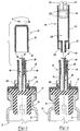
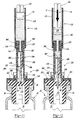
- the cover portion of the cap 50 Prior to use of the vial and transferset of this invention by a healthcare worker, for example, the cover portion of the cap 50 must first be removed as shown in Figure 3. This is accomplished with the disclosed embodiment of the transferset 20 simply by twisting the distal end portion of the cap 50 as shown by arrow A in Figure 3. This twisting motion breaks the frangible connection 84 formed by the radial groove 82. The cover portion then comprises the distal portion of the tubular portion 76 and the closed distal end portion 80 as shown in Figure 3. The cover portion of the cap 50 is thus removed from the transferset 20 exposing the distal end 67 of the piercing member 48 and the tubular transfer member 46 as shown in Figure 3. As described above, the distal tubular portion 102 of the collar includes a rounded bead 104 which protects the fingers of the healthcare worker during removal of the cover portion of the cap 50 which will now be more fully understood from Figure 3.
- the transferset 20 with the cover portion of the cap 50 removed is now ready for receipt of an IV set or a conventional syringe 110 as shown in Figure 4.
- the syringe 110 is coaxially aligned with the axis of the tubular transfer member 46.
- the diameter of the barrel portion 68 of the piercing member 48 is equal to or greater than the diameter of the nozzle portion 114 of the syringe, such that the nozzle portion 114 of the syringe will engage the distal end 67 of the piercing member 48.
- the syringe 110 is then secured to the tubular transfer member 46 and the piercing portion 70 of the piercing member 48 is driven through the central portion 42 of the resilient stopper 34 as shown in Figures 5 and 6.
- the tubular nozzle portion 114 of the syringe 110 is driven into the open distal end 64 of the tubular transfer member 46, the free end of the nozzle portion 114 is driven against the distal 67 of the piercing member 48, which drives the piercing end 72 through the central portion 42 of the stopper 34 as shown in Figure 5.
- the reduced diameter piercing portion 70 of the piercing member 48 is then driven through the central portion 42 of the stopper by threading the male thread of the Luer lock 60 at the distal end of the tubular transfer member 46 into the female thread 130 of the Luer lock on the extension or collar 129 of the syringe as shown in Figure 6.
- the threading of the syringe on the distal end of the tubular transfer member 46 drives the tubular nozzle portion 114 of the syringe 110 into the internal surface 64 of the tubular transfer member 46 and the free end of the tubular nozzle portion against the distal end 67 of the barrel portion 68 of the piercing member 48, which drives the piercing portion 70 of the piercing member through the central portion 42 of the stopper 34, establishing fluid communication through the external channel 74 and the interior 32 of the vial 22 as discussed more fully hereinbelow.
- the piercing of the center portion 42 of the stopper 34 by the piercing member 48 is facilitated by the circular sealing lip 54 on the proximate end of the tubular transfer member 46, which stretches and prestresses the unsupported central portion 42 of the stopper which overlies the tubular portion 36.
- the liquid diluent or solvent may now be transferred to the interior of the vial 22 simply by depressing the plunger 116 of the vial 110 as shown by arrow B in Figure 6.
- the liquid in the interior 128 of the syringe is thus ejected through the tubular nozzle portion 114 into the external channel 74 of the piercing member 48 into the tubular portion 34 of the stopper and thus into the interior 32 of the vial 22.
- one configuration of the generally longitudinal channel 74 in the piercing member 48 is a V-shaped channel 74 which is relatively simple to manufacture. Further, the use of a V-shaped channel having an angle of about 15° to 60° does not materially weaken the piercing member and provides adequate communication between the interior 32 of the vial and the tubular transfer member 46 through the channel 74. A larger angle of about 45° to 60° may be preferred to limit manufacturing problems and avoid potential blockage of the groove. Further, the channel 74 may be of any convenient shape, including rectangular.
- the resilient elastomeric central rim portion 42 of the stopper will be deformed into and partially fill the channel 74 in the piercing member when the piercing portion 70 penetrates the stopper.
- the deformation and stretching of the central portion 42 of the stopper over the opening of the vial by the sealing lip 54 of the tubular transfer member however reduces the volume of elastomeric material which is deformed into the channel 74, thereby improving fluid communication through the external channel 74.
- the liquid medicament is fully reconstituted by shaking the assembly as shown in Figure 7.
- the liquid medicament 136 may then be reaspirated into the same or a different syringe simply by withdrawing the plunger 116 into the tubular body portion 112 in the opposite direction from arrow B in Figure 6. It is important to note from Figure 7 that the liquid medicament 136 is transferred from the vial 122 through the external channel 74, then from the external channel into the tubular transfer member 46 to the syringe (not shown).
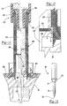
- Figures 11 to 15 illustrate an alternative embodiment of the vial transferset and method of this invention, wherein the fluid pressure in the syringe is utilized to drive the piercing member through the central portion of the stopper rather than mechanical force as described above in regard to Figures 1 to 10.
- the components of the transferset 220 have been numbered in the same sequence as the transferset 20 shown in Figures 1 to 10, except that the components of the transferset 220 are numbered in the 200 series for ease of description and reference to Figures 1 to 10 described above.
- the vial 22, stopper 34 and syringe 110 may, however, be identical to the same components described above and are therefore numbered the same.
- the tubular transfer member 246 has an axial length which is greater than the axial length of the piercing member 248, such that the distal end 267 of the piercing member is recessed in the smaller diameter opening 264 of the tubular transfer member a distance equal to or greater than the length of the tubular nozzle 114 of the syringe 110. This can be accomplished either by reducing the axial length of the piercing member 248 or increasing the length of the tubular transfer member 246 as shown in Figures 11 to 15.
- the piercing end 272 of the piercing member 248 is then driven through the center portion 42 of the stopper 34 by moving the head 118 of the plunger 116 of syringe 110 toward the nozzle 114 of the syringe, which drives the liquid 140 in the tubular body portion 112 of the syringe against the radial rib 275 of the piercing member 248.
- the radial rib 275 on the piercing member 248 of the transferset 220 shown in Figures 11 to 15 provides a fluid seal.
- the radial sealing rim 275 extends into the external generally longitudinal channel 274 and the radial sealing rib 275 has an external diameter generally equal to or slightly greater than the internal diameter of the internal cylindrical surface 266 of the tubular transfer member 46.
- the tubular transfer member includes a second enlarged bore 280 adjacent the proximate end having an internal diameter greater than the external diameter of the radial sealing rib 275.
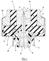
- the preferred alternative embodiment of the transferset 320 shown in Figures 16 to 18 operates and is assembled in the same manner as the embodiment of the transferset 20 shown in Figures 1 to 10.
- the components of the transferset 320 are generally the same, including a tubular transfer member 346, a piercing member 348, a generally cup-shaped cap 350 and a collar member 352.
- the components of the transferset 320 are numbered in the same sequence as the components of the transferset 20 shown in Figures 1 to 10 except that the components of the embodiment of the transferset 320 shown in Figures 16 to 18 are numbered in the 300 series.
- the features of the components are also numbered in the same sequence for ease of reference to the above description and to avoid duplication of the description of this embodiment.
- the tubular transfer member 346 includes an annular or circular sealing lip 354, a Luer lock connector 360 at its distal end, a first smaller internal diameter 364 and a larger proximate internal diameter 366 as described above.
- the following description of the components of the transferset 320 shown in Figures 16 to 18 will therefore be limited to the features which differ from the features of the transferset 20 shown in Figures 1 to 10.
- the tubular transfer member 346 includes an integral generally tubular connector portion 402, which in this embodiment, surrounds the proximate end of the tubular transfer member and is integrally joined to the remainder of the tubular transfer member at 404.
- the external surface of the connector portion 402 includes a radially projecting rounded rib 358 which is received in a groove 392 formed in the inner wall of the cap, providing a simplified snap-in interlock between the tubular transfer member 346 and the cap 350.
- the threaded Luer connector 360 on the tubular transfer member is also slightly modified; however, the Luer connector 360 is also conventional.
- the inner wall of the tubular portion 376 of the cap 350 also includes a plurality of sealing ribs 406 in this embodiment which engage the outer wall of the connector portion 402 of the tubular transfer member 346 which seal the connection between the cap and the tubular transfer member and prevent contamination of the transferset.
- the piercing member 348 has also been modified in this embodiment.
- the piercing end 372 of the piercing member 348 is slightly rounded to prevent premature penetration of the planar rim portion 38 of the stopper 34 shown, for example, in Figure 1. That is, the slightly rounded piercing end 372 will deform and stretch the planar rim portion 38 of the stopper, but will not partially penetrate the rim portion as shown in Figure 1.
- the piercing end 372, however, is "relatively sharp" and will pierce the planar rim portion of the elastomeric stopper 34 when the piercing member 348 is driven into the stopper as described above.
- the external channel 374 in the piercing member 348 terminates short of the piercing end as shown in Figure 17, such that the channel 374 includes a rounded end wall 408 spaced slightly from the proximate end of the relatively sharp piercing end 372. Terminating the external channel 374 a few millimeters (e.g. 7 mm) short of the piercing end 372 strengthens the piercing end 372 for penetration of the planar rim portion 38 of the stopper.
- the piercing member 348 is releasably retained in the tubular transfer member by an interlocking rib and groove as best shown in Figures 16 and 17.
- the piercing member includes an arcuate groove 410 adjacent the radial rib 375 and the internal surface 364 of the tubular transfer member 346 includes an interlocking arcuate rib 412 as shown in Figure 16 which releasably retains the piercing member 348 in the tubular transfer member 346.
- the barrel portion includes two spaced flats 414 which receive the mold ejector pins (not shown) which make it easier to remove the piercing member from the mold, but the flats do not form a functional part of the invention.
- the transferset 320 shown in Figures 16 may be preassembled in bulk with the collar for distribution to pharmaceutical companies, for example, for attachment to a vial under sterile conditions.
- the barrel portion 368 of the tubular transfer member further includes spaced flats which receive ejector pins in a mold to simplify release of the piercing member 348 from the mold, but are not functional in the transferset assembly 320.
- the distal end 367 of the piercing member 348 is rounded which also simplifies molding of the piercing member 348.
- the components of the transferset 328 are assembled and secured to a vial 22 as described above.
- the end 300 of the tubular portion 396 is crimped into the reduced diameter neck portion 28 of the vial as described above.
- the assembly of the transferset 320 on the vial drive the sealing lips 354 and 386 of the tubular transfer member into the planar radial rim portion 38 of the stopper, sealing the assembly.
- the cover portion of the cap 350 is then removed by twisting the distal end, breaking the frangible connection 384 as described.
- the transferset may then be utilized to transfer fluid to or from the vial by connecting a syringe 110 or IV set (not shown) to the Luer lock connector 360 as described above.
- the operation of the transferset 320 in transferring fluid to or from a vial is the same as described above in regard to Figures 1 to 10.
- the tubular transfer member 46, 246 and 346 may be polygonal, in which case, the barrel portion 68, 268 and 368 of the piercing member 48, 248 and 348 may be similarly polygonal and the tubular portion 76, 276 and 376 of the cap may either by cylindrical or polygonal.
- the collar 52, 252 and 352 may be formed of any suitable malleable material or may also be formed of a suitable plastic although in the disclosed embodiment the collar may be formed of aluminum.
- the piercing member and tubular transfer member may be formed of various materials including, for example, a medical grade polycarbonate having the appropriate strength and suitable for sterilization.
- the cap 50, 250 and 350 may also be formed of a medical grade polycarbonate.
- the external generally longitudinal channel 74, 274 and 374 in the piercing member 48, 248 and 348 respectively may be of various configuration including, for example, a spiral or a discontinuous longitudinal groove.
Landscapes
- Health & Medical Sciences (AREA)
- Pharmacology & Pharmacy (AREA)
- Life Sciences & Earth Sciences (AREA)
- Animal Behavior & Ethology (AREA)
- General Health & Medical Sciences (AREA)
- Public Health (AREA)
- Veterinary Medicine (AREA)
- Medical Preparation Storing Or Oral Administration Devices (AREA)
Description
Thus, as described above, the
Claims (28)
- A fluid transfer assembly for establishing fluid communication between a syringe (110) or the like and a sealed vial (22), said vial (22) having an open end, a rim (30) surrounding said open end, a reduced diameter neck portion (28) adjacent said rim (30) and a pierceable stopper (34) received in and sealing said vial open end, said stopper (34) having a rim portion (38) received over said vial rim (30), said transfer assembly (20,220,320) comprising:characterized bya tubular transfer member (46,246,346) having an open proximate end sealingly supported on said stopper rim portion (38) in alignment with said vial open end and an open distal end (62) adapted to receive a syringe tip in sealed communication;a piercing member (48,248,348) received within said tubular transfer member (46,246,346) reciprocally supported by an internal surface (64) of said transfer member (46,246,346), said piercing member (48,248,348) having a distal end and a piercing end (72,372) opposite said stopper rim portion (38); anda cap (50,250,350) having a proximate radial rim portion (78) adjacent an open end, a tubular portion (76) surrounding said tubular transfer member (46,246,346) and a closed distal end (67) enclosing said open distal end of said transfer member (46,246,346) and said distal end (67) of said piercing member (48),
the piercing member (48,248,348) adapted to pierce said stopper (34) when after removal of the cap (50,250,350) the syringe (110) is driven against said distal end (67) of said piercing member (48,248,348); and
a collar (52,252,352) having a radial portion (78) received over said cap radial rim portion (78), a tubular portion (96) surrounding said cap radial rim portion (78) and said vial rim (30) and a distal radial portion (100) received in said vial neck portion (28) of said vial (22) beneath said vial rim (30) permanently securing said transfer assembly (20,220,320) to said vial (22). - The fluid transfer assembly defined in claim 1, wherein said piercing member (48) includes an external generally longitudinal channel (74,274,374) providing communication between said vial open end and said tubular transfer member (46,246,346) when said piercing member (48) pierces said stopper (34).
- The fluid transfer assembly defined in claim 1, wherein said piercing member (46,246,346) piercing end extends beyond said tubular transfer member (46,246,346) and said piercing member (48,248,348) is releasably restrained in said tubular transfer member (46,246,346) with said sharp piercing end (72,372) partially penetrating said stopper (34).
- The fluid transfer assembly defined in claim 1, wherein said tubular portion (76) of said cap (50,250,350) includes a radial groove (82) weakening the wall of said tubular portion (76) for removal of said closed distal end from said fluid transfer assembly (20,220,320) prior to use.
- The fluid transfer assembly defined in claim 1, wherein said open distal end (62) of said transfer member (46,246,346) includes an external Luer connector (60,260,360) for receiving a Luer connector (130) of said syringe (110).
- The fluid transfer assembly defined in claim 1, wherein said radial rim portion of said tubular transfer member (46,246,346) includes a projecting circular sealing lip (54,354) surrounding said tubular portion of said transfer member (46,246,346) which engages said stopper rim portion (38), deforming and stretching said stopper rim portion (38) over said vial open end, sealing the communication between said vial open end and said tubular transfer member (46,246,346) when said piercing member (48,248,348) pierces said stopper (34).
- The fluid transfer assembly defined in claim 6, wherein said circular lip (54,354) of said transfer member (46,246,346) extends generally perpendicular to said radial rim portion of said transfer member (46,246,346) and includes a pointed edge which bites into said rim portion (38) of said stopper (34).
- The fluid transfer assembly defined in claim 6, wherein said radial rim portion of said cap (50,250,350) includes a circular sealing lip surrounding said tubular portion (76) of said cap (50,250,350) which engages said stopper rim portion (38) in sealed relation providing a seal to maintain the sterility of said fluid transfer assembly (20,220,320) when assembled on said vial (22).
- The fluid transfer assembly defined in claim 1, wherein said tubular portion (76) of said cap (50,250,350) includes a radial groove (82) weakening the wall of said tubular portion (76) for removal of said closed distal end of said cap (50,250,350) and said collar radial portion includes a tubular portion overlying said groove (82) in said cap (50,250,350).
- The fluid transfer assembly defined in claim 1, wherein said piercing member distal end is cylindrical having an external diameter generally equal to an internal surface of said tubular transfer member (46,246,346) adjacent said distal end of said transfer member (46,246,346) supporting said piercing member (48,248,348) generally perpendicular to said rim portion (30) of said stopper (34).
- The fluid transfer assembly defined in claim 10, wherein said piercing member (48,248,348) includes a radial lip (75,275,375) received in an enlarged counter bore (280) in said tubular transfer member (46,246,346) which releasably retains said piercing member (48,248,348) in said tubular transfer member (46,246,346) with said sharp piercing end (72,372) partially penetrating said stopper (34) prior to use.
- The fluid transfer assembly defined in claim 1, wherein said tubular transfer member (48,248,348) proximate end includes a radial flange which interlocks with said cap (50,250,350).
- The fluid transfer assembly defined in claim 1, wherein said collar (52,252,352) is formed of a relatively thin malleable metal and said tubular portion (96) is crimped into said vial neck beneath said vial rim (30) permanently securing said transfer assembly (20,220,320) to said vial (22).
- A method of transferring fluid medicament between a conventional sealed vial (22) and a second container (110), said vial (22) having an open end, a rim (30) surrounding said open end, a reduced diameter neck (28) adjacent said rim (30) and a pierceable stopper (34) received in and sealing said vial open end, said stopper (34) having a rim portion (38) received over said vial rim (30), said second container (110) including a tubular connector portion, said method comprising:mounting a fluid transfer assembly (20,220,320) on said vial, said transfer assembly (20,220,320) including a tubular transfer member (46,246,346) having an open proximate end adapted to be sealingly supported on said stopper rim (38) of said vial (22) in alignment with said vial open end and an open distal end (62) having a connector adapted to be connected to said connector portion of said second container (110), a piercing member (48,248,348) received in said tubular transfer member (46,246,346) reciprocally supported by an internal surface (64) of said tubular transfer member (46,246,346), said piercing member (48,248,348) having a generally sharp piercing end (72,372), an opposed distal end (67) and an external channel (74,274,374), and a tubular collar (52,252,352), said method including mounting said fluid transfer assembly (20,220,320) on said vial (22) by securing said collar (52,252,352) an said neck portion (28) of said vial (22) beneath said rim (30) with said tubular transfer member (46,246,346) sealingly engaging said stopper rim portion (38) and said piercing member (48,248,348) coaxially aligned with said vial open end and said piercing end (48,248,348) adjacent said stopper (34);attaching said connector portion of said second container (110) to said connector on said tubular transfer member (46,246,346), driving said piercing member generally sharp piercing end (72,372) through said stopper rim portion (38) when said second container (110) is driven against said distal end (67) of said piercing member (48,248,348), said external channel (74,274,374) in said piercing member (48,248,348) establishing fluid communication between said vial (22) and said second container (110) through said tubular transfer member (46,246,346), thereby permitting transfer of fluid from said second container (110) to said vial (22) or from said vial (22) to said second container (110).
- The method of transferring fluid medicament between a conventional sealed vial (22) and a second container (110) as defined in claim 14, wherein said fluid transfer assembly (20,220,320) includes a cup-shaped cap (50,250,350) having a radial rim portion (78) adjacent an open end, said method including mounting said cap (50,250,350) with said rim portion (78) opposite said stopper radial rim portion (38), a tubular portion (96) surrounding said transfer member (46,246,346) and a cover portion enclosing said open distal end (62) of said transfer member (46,246,346) and said distal end (67) of said piercing member (48,248,348), said cover portion attached to said tubular portion (96) by a frangible connector (84), said method including mounting said fluid transfer assembly (20,220,320) on said vial (22) under sterile conditions with said cup-shaped cap (50,250,350) enclosing said transfer assembly (20,220,320) maintaining said tubular transfer member (46,246,346) and said piercing member (48,248,348) under sterile conditions until use, then removing said cover portion by breaking said frangible connector (84), then attaching said second container (110) like a syringe to said tubular transfer member (46,246,346).
- The method of transferring fluid medicament between a conventional sealed vial (22) and a second container (110) as defined in claim 14, wherein said collar (52,252,352) is formed of a relatively thin malleable metal having a tubular portion (96) and a radial portion, said method including telescopically receiving said collar (52,252,352) over the components of said fluid transfer assembly (20,220,320) and said vial rim (30) with said radial portion overlying said components of said transfer assembly (20,220,320) and said tubular portion (96) receiving said vial rim (30), then crimping a free end (100) of said tubular portion (96) beneath said vial rim (30) extending into said vial neck permanently securing said transfer assembly (20,220,320) on said vial (22).
- The method of transferring fluid medicament between a conventional sealed vial (22) and a second container (110) as defined in claim 16, wherein said tubular transfer member (46,246,346) includes a generally circular sealing lip (54,354) surrounding said tubular portion of said transfer member (46,246,346) which is generally aligned with said tubular portion, said method including compressing said sealing lip (54,354) against said rim portion (38) of said stopper (34) as said collar (52,252,352) is crimped an said vial (22), stretching said rim portion (98) of said stopper (34) before piercing of said stopper (34) by said piercing member (48,248,348).
- The method of transferring fluid medicament between a conventional sealed vial (22) and a second container (110) as defined in claim 17, wherein said circular sealing lip (54,354) of said tubular transfer member (46,246,346) has a pointed edge, wherein said method includes pressing said sealing lip (54,354) against said rim portion (98) of said stopper (34), such that said sealing lip (54,354) pointed edge bites into said stopper rim portion (38) providing an improved seal of the communication between said vial open end and said tubular transfer member (46,246,346) when said piercing member (48,248,348) pierces said stopper (34).
- The method of transferring fluid medicament between a conventional sealed vial (22) and a second container (110) as defined in claim 17, wherein said piercing member (48,248,348) is releasably retained in said tubular transfer member (46,246,346) with said piercing end (72,372) extending beyond said tubular transfer member (46,246,346), said method including compressing said sealing lip of said tubular transfer member and said piercing end (72,372) of said piercing member (48,248,348) against said rim portion (38) of said stopper (34) as said collar (52,252,352) is crimped an said vial (22), said piercing end (72,372) of said piercing member (48,248,348) resiliently deforming said rim portion (38) of said stopper (34).
- The method of transferring fluid medicament between a conventional sealed vial (22) and a second container (110) as defined in claim 14, wherein said connector (60,260,360) on said tubular transfer member (46,246,346) and said connector portion (130) of said second container (110) are mating threaded connectors and said connector portion (130) of said second container (110) extends beyond a body portion (112) of said second container (110), said method including threading said threaded connector portion (130) of said second container (110) on said threaded connector (60,260,360) of said tubular transfer member (46,246,346) thereby driving said nozzle portion of said second container (110) against said distal end (67) of said piercing member (48,248,348) and said sharp end (72,372) of said piercing member (48, 248,348) through said stopper rim portion (38), thereby establishing said fluid communication between said second container (110) and said vial (22).
- The method of transferring fluid medicament between a conventional sealed vial (22) and a second container (110) as defined in claim 14, wherein said second container (110) is a syringe having a tubular body portion (112) initially filled with fluid, a plunger (116) retracted within said syringe tubular body portion (112), and a reduced diameter tubular nozzle portion (114) extending beyond said tubular body portion (112), said piercing member (48,248,348) including a radial sealing portion engaging an interior surface (64) of said tubular transfer member (46,246,346), said method including attaching said syringe (110) on said connector (60,260,360) on said tubular transfer member (46,246,346) thereby establishing fluid communication between said nozzle portion (114) of said syringe (110) and said distal end (62) of said tubular transfer member (46,246,346), then driving said plunger (116) of said syringe (110) toward said nozzle portion (114), driving fluid against said radial sealing portion of said piercing member (48,248,348) and driving said piercing end (72,372) of said piercing member through said stopper (34), thereby establishing said communication between said syringe (110) and said vial (22).
- The method of transferring fluid medicament between a conventional sealed vial (22) and a second container (110) as defined in claim 14, wherein said fluid transfer assembly (20,220,320) includes a cup-shaped cap (50,250,350), said cap (50,250,350) including a tubular portion (76) having an internal diameter greater than said tubular transfer member (46,246,346), and an open proximate end, a radial rim portion adjacent said open end and a closed distal end (80), said tubular transfer member (46,246,346) including a circular sealing lip (54,354) surrounding said tubular portion of said tubular transfer member (46,246,346), said method including assembling said fluid transfer assembly (20,220,320) by inserting said piercing member (48,248,348) in said tubular transfer member (46,246,346) with said piercing end (72,372) adjacent said proximate end of said tubular transfer member (46,246,346), receiving said cap (50,250,350) over said tubular transfer member (46,246,346) with said closed distal end enclosing said distal ends of said tubular transfer member (46,246,346) and said piercing member (48,248,348), then assembling said tubular transfer member (46,246,346), piercing member (48,248,348) and cap (50,250,350) an said rim portion (38) of said stopper (34) with said tubular transfer member (46,246,346) and said piercing member (48,248,348) in generally coaxial alignment with said open end of said vial (22), generally perpendicular to said stopper rim portion (38), then securing said assembly an said vial (22) with said collar (52,252,352) and simultaneously compressing said proximate end of said tubular transfer member (46,246,346) against said stopper (34), compressing said circular sealing lip (54,354) against said stopper rim portion (38), stretching said lip portion (54,354) over said vial open end and sealing communication between said piercing member external channel (74,274,374) and said tubular transfer member (46,246,346) when said piercing member (48,248,348) pierces said stopper (34).
- The method of transferring fluid medicament between a conventional sealed vial (22) and a second container (110) as defined in claim 22, wherein said piercing member (48,248,348) is assembled in said tubular transfer member (46,246,346) with said piercing end (72,372) extending beyond said tubular transfer member proximate end, said method then including compressing said tubular transfer member (46,246,346) on said stopper rim portion (38) with said piercing end (72,372) of said piercing member (48,248,348) deforming said stopper (34).
- The method of transferring fluid medicament between a conventional sealed vial (22) and a second container (110) as defined in one of claims 15-23, wherein said radial rim portion of said cap (50,250,350) includes a circular sealing lip surrounding said tubular portion of said cap (50,250,350) adjacent to said tubular portion, said method including pressing said circular sealing lip of said cap (50,250,350) against said rim portion (38) of said stopper (34), providing a seal surrounding said piercing member (48,248,348).
- A method of securing a fluid transfer assembly (20,220,320) as defined in one of claims 1-13 on a conventional vial (22) and stopper (34) assembly, said vial (22) having an open end, a radial rim portion (30) surrounding said open end and a reduced diameter neck portion (28) adjacent said open end, said stopper (34) formed of an elastomeric material and including a tubular portion received in said vial open end and an integral generally planar rim portion (38) overlying said vial rim portion (30), said method comprising:assembling said fluid transfer assembly (20,220,320) on said stopper generally planar rim portion (38), said fluid transfer assembly (20,220,320) including a generally flat annular surface overlying said planar rim portion (38) of said stopper (34) having a circular sealing lip projecting from generally flat annular surface;securing said fluid transfer assembly (20,220,320) on said vial (22) and stopper (34) assembly with said collar (52,252,352), said method including disposing said collar tubular portion (96) over said fluid transfer assembly (20,220,320) and said vial rim portion (36) with said collar (52,252,352) radially inwardly projecting annular portion receiving said generally flat annular surface of said fluid transfer assembly (20,220,320), compressing said circular sealing lip projecting from said flat annular surface into said stopper (34) generally planar rim portion (38) and crimping a distal end (100) of said collar tubular portion (96) into said vial neck beneath said vial rim (30).
- The method of securing a fluid transfer assembly on a conventional vial and stopper assembly as defined in claim 25, wherein said circular sealing lip includes a sharp edge having a diameter greater than an inside diameter of said vial open end, such that said circular sealing lip overlies a portion of said stopper (34) generally planar rim portion (38) which overlies said vial radial rim portion (30), said method including compressing said sharp edge of said circular sealing lip into said stopper (34) generally planar rim portion (38) while said distal end (100) of said collar (52,252,352) is crimped into said vial neck portion (28), causing said sharp edge of said sealing lip to penetrate said stopper generally planar rim portion (38) sealing the communication between said vial open end and said fluid transfer assembly (20,220,320).
- The method of securing a fluid transfer assembly on a conventional vial and stopper assembly as defined in claim 25, wherein said circular sealing lip has a diameter less than an inside diameter of said vial open end and said stopper tubular portion, such that said circular sealing lip overlies an unsupported central portion of said stopper generally planar rim portion (38), said method including compressing said circular sealing lip into said stopper generally planar rim portion (38) as said distal end (100) of said collar tubular portion (96) is crimped into said vial neck portion (28), said circular sealing lip stretching and prestressing said central portion of said stopper planar rim portion (38).
- The method of securing a fluid transfer assembly an a conventional vial and stopper assembly as defined in claim 27, said method including compressing said piercing end (72,372) of said piercing member (48,248,348) into said stopper generally planar rim portion (38) to partially, but not totally penetrate said generally planar rim portion (38) of said stopper (34) as said collar tubular portion (96) is crimped into said vial neck portion (28).
Applications Claiming Priority (3)
| Application Number | Priority Date | Filing Date | Title |
|---|---|---|---|
| US09/031,302 US6003566A (en) | 1998-02-26 | 1998-02-26 | Vial transferset and method |
| US31302 | 1998-02-26 | ||
| PCT/US1999/004077 WO1999043282A1 (en) | 1998-02-26 | 1999-02-25 | Vial transferset and method |
Publications (2)
| Publication Number | Publication Date |
|---|---|
| EP1056426A1 EP1056426A1 (en) | 2000-12-06 |
| EP1056426B1 true EP1056426B1 (en) | 2002-10-02 |
Family
ID=21858695
Family Applications (1)
| Application Number | Title | Priority Date | Filing Date |
|---|---|---|---|
| EP99908450A Expired - Lifetime EP1056426B1 (en) | 1998-02-26 | 1999-02-25 | Vial transferset and method |
Country Status (6)
| Country | Link |
|---|---|
| US (3) | US6003566A (en) |
| EP (1) | EP1056426B1 (en) |
| JP (1) | JP4216466B2 (en) |
| AU (1) | AU746615B2 (en) |
| DE (1) | DE69903266T2 (en) |
| WO (1) | WO1999043282A1 (en) |
Families Citing this family (144)
| Publication number | Priority date | Publication date | Assignee | Title |
|---|---|---|---|---|
| JP3777587B2 (en) * | 1999-04-09 | 2006-05-24 | ニプロ株式会社 | Liquid container |
| IL114960A0 (en) | 1995-03-20 | 1995-12-08 | Medimop Medical Projects Ltd | Flow control device |
| US5954104A (en) * | 1997-02-28 | 1999-09-21 | Abbott Laboratories | Container cap assembly having an enclosed penetrator |
| US6382442B1 (en) | 1998-04-20 | 2002-05-07 | Becton Dickinson And Company | Plastic closure for vials and other medical containers |
| US6681946B1 (en) | 1998-02-26 | 2004-01-27 | Becton, Dickinson And Company | Resealable medical transfer set |
| US6003566A (en) * | 1998-02-26 | 1999-12-21 | Becton Dickinson And Company | Vial transferset and method |
| US6209738B1 (en) | 1998-04-20 | 2001-04-03 | Becton, Dickinson And Company | Transfer set for vials and medical containers |
| US6378714B1 (en) * | 1998-04-20 | 2002-04-30 | Becton Dickinson And Company | Transferset for vials and other medical containers |
| US6957745B2 (en) * | 1998-04-20 | 2005-10-25 | Becton, Dickinson And Company | Transfer set |
| US6475183B1 (en) * | 1998-06-03 | 2002-11-05 | Baxter International Inc. | Direct dual filling device for sealing agents |
| EP1211184B1 (en) * | 1999-04-20 | 2010-01-20 | JMS Co., Ltd. | Cap for container and adaptor for liquid communication |
| SE9902610D0 (en) * | 1999-07-07 | 1999-07-07 | Astra Ab | Sealing device at medical container |
| US6607508B2 (en) | 2000-04-27 | 2003-08-19 | Invivotech, Inc. | Vial injector device |
| US6269976B1 (en) * | 2000-08-17 | 2001-08-07 | Saint-Gobain Calmar Inc. | Vial access spike adapter for pump sprayer |
| JP2002087968A (en) * | 2000-09-14 | 2002-03-27 | Otsuka Pharmaceut Factory Inc | Heparin liquid agent |
| FR2819174B1 (en) * | 2001-01-08 | 2003-06-13 | Pierre Frezza | BULB FOR PACKAGING AND TRANSFERRING LIQUID OR POWDER FOR MEDICAL USE IN A CONTAINER |
| US6474375B2 (en) | 2001-02-02 | 2002-11-05 | Baxter International Inc. | Reconstitution device and method of use |
| US20030032935A1 (en) * | 2001-08-10 | 2003-02-13 | Scimed Life Systems, Inc. | Packages facilitating convenient mixing and delivery of liquids |
| US7462366B2 (en) | 2002-03-29 | 2008-12-09 | Boston Scientific Scimed, Inc. | Drug delivery particle |
| US7114635B2 (en) * | 2002-05-10 | 2006-10-03 | Santen Pharmaceutical Co., Ltd. | Contamination preventive cap |
| CA2492339A1 (en) | 2002-06-12 | 2003-12-24 | Boston Scientific Limited | Bulking agents |
| US6874522B2 (en) * | 2002-06-18 | 2005-04-05 | Baxter International Inc. | Luer-actuated solution path connector with membrane and container using the connector and a method for establishing fluid communication with the container |
| US7842377B2 (en) | 2003-08-08 | 2010-11-30 | Boston Scientific Scimed, Inc. | Porous polymeric particle comprising polyvinyl alcohol and having interior to surface porosity-gradient |
| US8012454B2 (en) | 2002-08-30 | 2011-09-06 | Boston Scientific Scimed, Inc. | Embolization |
| US7883490B2 (en) | 2002-10-23 | 2011-02-08 | Boston Scientific Scimed, Inc. | Mixing and delivery of therapeutic compositions |
| DK1454609T3 (en) * | 2003-03-05 | 2013-02-11 | Csl Behring Gmbh | Transmission facility |
| US20040206416A1 (en) * | 2003-04-21 | 2004-10-21 | Paradis Joseph R. | Safety shield needle protector |
| US6948522B2 (en) * | 2003-06-06 | 2005-09-27 | Baxter International Inc. | Reconstitution device and method of use |
| JP3883527B2 (en) * | 2003-07-17 | 2007-02-21 | ニプロ株式会社 | Transfer needle |
| EP1647226B1 (en) * | 2003-07-18 | 2013-02-13 | Sekisui Chemical Co., Ltd. | Hermetically sealed container and vacuum test substance-collecting container |
| FR2858931B1 (en) | 2003-08-21 | 2007-04-13 | Becton Dickinson France | DEVICE FOR ORAL ADMINISTRATION OF A MEDICINAL PRODUCT |
| US7976823B2 (en) | 2003-08-29 | 2011-07-12 | Boston Scientific Scimed, Inc. | Ferromagnetic particles and methods |
| CA2541615C (en) * | 2003-10-30 | 2012-12-04 | Teva Medical Ltd. | Safety drug handling device |
| DE102004005435B3 (en) * | 2004-02-04 | 2005-09-15 | Haindl, Hans, Dr. | Medical transfer device |
| US7736671B2 (en) | 2004-03-02 | 2010-06-15 | Boston Scientific Scimed, Inc. | Embolization |
| US8173176B2 (en) | 2004-03-30 | 2012-05-08 | Boston Scientific Scimed, Inc. | Embolization |
| IL161660A0 (en) | 2004-04-29 | 2004-09-27 | Medimop Medical Projects Ltd | Liquid drug delivery device |
| US7311861B2 (en) | 2004-06-01 | 2007-12-25 | Boston Scientific Scimed, Inc. | Embolization |
| US7615041B2 (en) * | 2004-07-29 | 2009-11-10 | Boston Scientific Scimed, Inc. | Vial adaptor |
| US8425550B2 (en) | 2004-12-01 | 2013-04-23 | Boston Scientific Scimed, Inc. | Embolic coils |
| EP1853333A1 (en) * | 2004-12-23 | 2007-11-14 | Bracco Research S.A. | Liquid transfer device for medical dispensing containers |
| US20060184103A1 (en) * | 2005-02-17 | 2006-08-17 | West Pharmaceutical Services, Inc. | Syringe safety device |
| US7727555B2 (en) | 2005-03-02 | 2010-06-01 | Boston Scientific Scimed, Inc. | Particles |
| US7858183B2 (en) | 2005-03-02 | 2010-12-28 | Boston Scientific Scimed, Inc. | Particles |
| US7963287B2 (en) | 2005-04-28 | 2011-06-21 | Boston Scientific Scimed, Inc. | Tissue-treatment methods |
| US9463426B2 (en) | 2005-06-24 | 2016-10-11 | Boston Scientific Scimed, Inc. | Methods and systems for coating particles |
| WO2007015233A1 (en) * | 2005-08-01 | 2007-02-08 | Medimop Medical Projects Ltd | Liquid drug delivery system |
| DK1919432T3 (en) | 2005-08-11 | 2012-01-30 | Medimop Medical Projects Ltd | Liquid Medication Transfer Devices for Safe Safe Resting Connection on Medical Vials |
| US8007509B2 (en) | 2005-10-12 | 2011-08-30 | Boston Scientific Scimed, Inc. | Coil assemblies, components and methods |
| DE102005057547A1 (en) * | 2005-11-30 | 2007-05-31 | Clinico Gmbh | Device for transferring liquids, suspensions, and solid materials from first receptacle into second receptacle, has fastening device formed by conventional receptacle closure |
| US8152839B2 (en) | 2005-12-19 | 2012-04-10 | Boston Scientific Scimed, Inc. | Embolic coils |
| US8101197B2 (en) | 2005-12-19 | 2012-01-24 | Stryker Corporation | Forming coils |
| US7947368B2 (en) | 2005-12-21 | 2011-05-24 | Boston Scientific Scimed, Inc. | Block copolymer particles |
| US20070202186A1 (en) | 2006-02-22 | 2007-08-30 | Iscience Interventional Corporation | Apparatus and formulations for suprachoroidal drug delivery |
| DE102006009611A1 (en) * | 2006-03-02 | 2007-09-06 | Bernd Hansen | A system for preparing and providing a flowable medium formed by mixing a dry substance with a fluid |
| EP2540276B1 (en) | 2006-05-25 | 2016-03-16 | Bayer Healthcare LLC | Method of assembling a reconstitution device |
| US8414927B2 (en) | 2006-11-03 | 2013-04-09 | Boston Scientific Scimed, Inc. | Cross-linked polymer particles |
| IL182605A0 (en) | 2007-04-17 | 2007-07-24 | Medimop Medical Projects Ltd | Fluid control device with manually depressed actuator |
| EP2190518B1 (en) | 2007-09-18 | 2016-01-27 | Medimop Medical Projects Ltd. | Medicament mixing and injection apparatus |
| IL186290A0 (en) | 2007-09-25 | 2008-01-20 | Medimop Medical Projects Ltd | Liquid drug delivery devices for use with syringe having widened distal tip |
| US8870832B2 (en) * | 2007-11-08 | 2014-10-28 | Elcam Medical A.C.A.L Ltd | Vial adaptor and manufacturing method therefor |
| US7905873B2 (en) * | 2008-07-03 | 2011-03-15 | Baxter International Inc. | Port assembly for use with needleless connector |
| WO2010052707A1 (en) * | 2008-11-04 | 2010-05-14 | Situ Gen Ltd. | Dually activated connector |
| US8864725B2 (en) | 2009-03-17 | 2014-10-21 | Baxter Corporation Englewood | Hazardous drug handling system, apparatus and method |
| USD641080S1 (en) | 2009-03-31 | 2011-07-05 | Medimop Medical Projects Ltd. | Medical device having syringe port with locking mechanism |
| US9345640B2 (en) | 2009-04-14 | 2016-05-24 | Yukon Medical, Llc | Fluid transfer device |
| EP2724739B1 (en) | 2009-07-30 | 2015-07-01 | Tandem Diabetes Care, Inc. | Portable infusion pump system |
| US8281807B2 (en) | 2009-08-31 | 2012-10-09 | Medrad, Inc. | Fluid path connectors and container spikes for fluid delivery |
| CA2678198A1 (en) * | 2009-09-08 | 2011-03-08 | Duoject Medical Systems Inc. | Ez-linking device for fluid transfer |
| FR2950272B1 (en) * | 2009-09-23 | 2012-06-01 | Oreal | COSMETIC PRODUCT DISPENSER ON A RECEPTION SURFACE, DISTRIBUTION DEVICE AND ASSOCIATED METHOD. |
| USD630732S1 (en) | 2009-09-29 | 2011-01-11 | Medimop Medical Projects Ltd. | Vial adapter with female connector |
| JP5416529B2 (en) * | 2009-09-29 | 2014-02-12 | テルモ株式会社 | Drug administration device and drug administration device with drug container installed |
| IL201323A0 (en) | 2009-10-01 | 2010-05-31 | Medimop Medical Projects Ltd | Fluid transfer device for assembling a vial with pre-attached female connector |
| IL202070A0 (en) | 2009-11-12 | 2010-06-16 | Medimop Medical Projects Ltd | Inline liquid drug medical device |
| IL202069A0 (en) | 2009-11-12 | 2010-06-16 | Medimop Medical Projects Ltd | Fluid transfer device with sealing arrangement |
| EP2359799A1 (en) * | 2010-02-16 | 2011-08-24 | Fresenius Kabi Deutschland GmbH | Closure cap for a container for holding medicinal liquids and container |
| JP5709905B2 (en) | 2010-02-24 | 2015-04-30 | メディモップ・メディカル・プロジェクツ・リミテッド | Liquid transfer device including vial adapter with vent |
| EP2512399B1 (en) | 2010-02-24 | 2015-04-08 | Medimop Medical Projects Ltd. | Fluid transfer assembly with venting arrangement |
| EP2371342A1 (en) * | 2010-04-01 | 2011-10-05 | Siemens Healthcare Diagnostics Products GmbH | Device for storing and metering a solution |
| FR2962218B1 (en) * | 2010-07-02 | 2012-07-27 | Instrumentation Scient De Laboratoire Isl | METHOD FOR INJECTING A SAMPLE TO BE ANALYZED IN THE INJECTION TUBE OF A MEASURING CELL, IN PARTICULAR A DENSIMETER |
| CA2808888C (en) | 2010-08-25 | 2018-10-16 | Baxter International Inc. | Assembly to facilitate user reconstitution |
| US8734420B2 (en) | 2010-08-25 | 2014-05-27 | Baxter International Inc. | Packaging assembly to prevent premature activation |
| US20120078215A1 (en) * | 2010-09-28 | 2012-03-29 | Tyco Healthcare Group Lp | Two-piece vial transfer needle assembly |
| USD669980S1 (en) | 2010-10-15 | 2012-10-30 | Medimop Medical Projects Ltd. | Vented vial adapter |
| IL209290A0 (en) | 2010-11-14 | 2011-01-31 | Medimop Medical Projects Ltd | Inline liquid drug medical device having rotary flow control member |
| IL212420A0 (en) | 2011-04-17 | 2011-06-30 | Medimop Medical Projects Ltd | Liquid drug transfer assembly |
| BR112013028171A2 (en) * | 2011-05-02 | 2020-05-12 | Mouse Trap Design, Llc | DEVICE FOR MIXING A FLUID PLURALITY TO FORMULATE A MIXTURE AND TO DISPENSE THE MIXTURE |
| WO2013009897A1 (en) | 2011-07-11 | 2013-01-17 | Medpro Safety Products, Inc. | Fluid delivery device and methods |
| US20130053815A1 (en) * | 2011-08-23 | 2013-02-28 | Allergan, Inc. | High recovery vial adaptor |
| IL215699A0 (en) | 2011-10-11 | 2011-12-29 | Medimop Medical Projects Ltd | Liquid drug reconstitution assemblage for use with iv bag and drug vial |
| USD737436S1 (en) | 2012-02-13 | 2015-08-25 | Medimop Medical Projects Ltd. | Liquid drug reconstitution assembly |
| USD720451S1 (en) | 2012-02-13 | 2014-12-30 | Medimop Medical Projects Ltd. | Liquid drug transfer assembly |
| USD674088S1 (en) | 2012-02-13 | 2013-01-08 | Medimop Medical Projects Ltd. | Vial adapter |
| WO2013134614A2 (en) | 2012-03-08 | 2013-09-12 | Becton, Dickinson And Company | Drug reconstitution system |
| IL219065A0 (en) | 2012-04-05 | 2012-07-31 | Medimop Medical Projects Ltd | Fluid transfer device with manual operated cartridge release arrangement |
| JP6360036B2 (en) * | 2012-04-09 | 2018-07-18 | ベクトン・ディキンソン・アンド・カンパニーBecton, Dickinson And Company | Medicine bottle dosing system and method |
| US9180242B2 (en) | 2012-05-17 | 2015-11-10 | Tandem Diabetes Care, Inc. | Methods and devices for multiple fluid transfer |
| IL221634A0 (en) | 2012-08-26 | 2012-12-31 | Medimop Medical Projects Ltd | Universal drug vial adapter |
| IL221635A0 (en) | 2012-08-26 | 2012-12-31 | Medimop Medical Projects Ltd | Drug vial mixing and transfer device for use with iv bag and drug vial |
| JP5868555B2 (en) | 2012-09-13 | 2016-02-24 | メディモップ・メディカル・プロジェクツ・リミテッド | Nested female vial adapter |
| USD734868S1 (en) | 2012-11-27 | 2015-07-21 | Medimop Medical Projects Ltd. | Drug vial adapter with downwardly depending stopper |
| US9481903B2 (en) | 2013-03-13 | 2016-11-01 | Roche Molecular Systems, Inc. | Systems and methods for detection of cells using engineered transduction particles |
| WO2014160418A2 (en) | 2013-03-13 | 2014-10-02 | GeneWeave Biosciences, Inc. | Non-replicative transduction particles and transduction particle-based reporter systems |
| US9173998B2 (en) | 2013-03-14 | 2015-11-03 | Tandem Diabetes Care, Inc. | System and method for detecting occlusions in an infusion pump |
| JP6255163B2 (en) * | 2013-04-05 | 2017-12-27 | テルモ株式会社 | Drug preparation tool |
| IL225734A0 (en) | 2013-04-14 | 2013-09-30 | Medimop Medical Projects Ltd | Ready-to-use drug vial assemblages including drug vial and drug vial closure having fluid transfer member, and drug vial closure therefor |
| CN110302004B (en) | 2013-05-03 | 2023-04-28 | 科尼尔赛德生物医学公司 | Apparatus and method for ocular injection |
| DK2983745T3 (en) | 2013-05-10 | 2018-10-22 | West Pharma Services Il Ltd | Medical devices comprising ampoule adapter with interconnected module for dry drug |
| JP3205560U (en) | 2013-08-07 | 2016-08-04 | メディモップ・メディカル・プロジェクツ・リミテッド | Liquid transfer device for use with a drip liquid container |
| USD767124S1 (en) | 2013-08-07 | 2016-09-20 | Medimop Medical Projects Ltd. | Liquid transfer device with integral vial adapter |
| USD765837S1 (en) | 2013-08-07 | 2016-09-06 | Medimop Medical Projects Ltd. | Liquid transfer device with integral vial adapter |
| US20150096646A1 (en) | 2013-10-08 | 2015-04-09 | Stephanie Davidson | Needle-less vial assembly for use with needle-free system |
| US9540675B2 (en) | 2013-10-29 | 2017-01-10 | GeneWeave Biosciences, Inc. | Reagent cartridge and methods for detection of cells |
| EP3087010B1 (en) * | 2013-12-27 | 2018-12-12 | William Beaumont Hospital | Container closure, container assembly and method for utilizing the same |
| USD757933S1 (en) | 2014-09-11 | 2016-05-31 | Medimop Medical Projects Ltd. | Dual vial adapter assemblage |
| CN108601706B (en) | 2015-01-05 | 2019-06-25 | 麦迪麦珀医疗工程有限公司 | With for guaranteeing the vial adapter component of proper use of quick release vial adapter |
| CA2918410A1 (en) * | 2015-01-21 | 2016-07-21 | Liqui-Box Corporation | Piercing fitment assembly for flexible container |
| ES2846783T3 (en) | 2015-03-10 | 2021-07-29 | Regeneron Pharma | Aseptic drilling system |
| EP3319576B1 (en) | 2015-07-16 | 2019-10-02 | West Pharma. Services IL, Ltd | Liquid drug transfer devices for secure telescopic snap fit on injection vials |
| US10351893B2 (en) | 2015-10-05 | 2019-07-16 | GeneWeave Biosciences, Inc. | Reagent cartridge for detection of cells |
| WO2017066406A1 (en) * | 2015-10-13 | 2017-04-20 | J&J SOLUTIONS, INC. d/b/a Corvida Medical | Automated compounding equipment for closed fluid transfer system |
| USD801522S1 (en) | 2015-11-09 | 2017-10-31 | Medimop Medical Projects Ltd. | Fluid transfer assembly |
| EP3380058B1 (en) | 2015-11-25 | 2020-01-08 | West Pharma Services IL, Ltd. | Dual vial adapter assemblage including drug vial adapter with self-sealing access valve |
| US10022531B2 (en) | 2016-01-21 | 2018-07-17 | Teva Medical Ltd. | Luer lock adaptor |
| IL245803A0 (en) | 2016-05-24 | 2016-08-31 | West Pharma Services Il Ltd | Dual vial adapter assemblages including vented drug vial adapter and vented liquid vial adapter |
| IL245800A0 (en) | 2016-05-24 | 2016-08-31 | West Pharma Services Il Ltd | Dual vial adapter assemblages including identical twin vial adapters |
| IL246073A0 (en) | 2016-06-06 | 2016-08-31 | West Pharma Services Il Ltd | Fluid transfer devices for use with drug pump cartridge having slidable driving plunger |
| IL247376A0 (en) | 2016-08-21 | 2016-12-29 | Medimop Medical Projects Ltd | Syringe assembly |
| USD832430S1 (en) | 2016-11-15 | 2018-10-30 | West Pharma. Services IL, Ltd. | Dual vial adapter assemblage |
| IL249408A0 (en) | 2016-12-06 | 2017-03-30 | Medimop Medical Projects Ltd | Liquid transfer device for use with infusion liquid container and pincers-like hand tool for use therewith for releasing intact drug vial therefrom |
| IL251458A0 (en) | 2017-03-29 | 2017-06-29 | Medimop Medical Projects Ltd | User actuated liquid drug transfer devices for use in ready-to-use (rtu) liquid drug transfer assemblages |
| BR112019020705A2 (en) | 2017-05-05 | 2020-05-12 | Regeneron Pharmaceuticals, Inc. | AUTOINJECTOR |
| US11077444B2 (en) | 2017-05-23 | 2021-08-03 | Roche Molecular Systems, Inc. | Packaging for a molecular diagnostic cartridge |
| IL254802A0 (en) | 2017-09-29 | 2017-12-31 | Medimop Medical Projects Ltd | Dual vial adapter assemblages with twin vented female vial adapters |
| US11291802B2 (en) * | 2017-10-09 | 2022-04-05 | Becton, Dickinson And Company | Fluid storage unit, systems, and methods for catheter priming |
| USD903864S1 (en) | 2018-06-20 | 2020-12-01 | West Pharma. Services IL, Ltd. | Medication mixing apparatus |
| JP1630477S (en) | 2018-07-06 | 2019-05-07 | ||
| USD923812S1 (en) | 2019-01-16 | 2021-06-29 | West Pharma. Services IL, Ltd. | Medication mixing apparatus |
| JP1648075S (en) | 2019-01-17 | 2019-12-16 | ||
| US11918542B2 (en) | 2019-01-31 | 2024-03-05 | West Pharma. Services IL, Ltd. | Liquid transfer device |
| WO2020222220A1 (en) | 2019-04-30 | 2020-11-05 | West Pharma. Services IL, Ltd. | Liquid transfer device with dual lumen iv spike |
| US11464914B2 (en) * | 2019-10-21 | 2022-10-11 | Ripple Therapeutics Corporation | Intravitreal injector |
| USD956958S1 (en) | 2020-07-13 | 2022-07-05 | West Pharma. Services IL, Ltd. | Liquid transfer device |
| USD1007676S1 (en) | 2021-11-16 | 2023-12-12 | Regeneron Pharmaceuticals, Inc. | Wearable autoinjector |
Family Cites Families (260)
| Publication number | Priority date | Publication date | Assignee | Title |
|---|---|---|---|---|
| US37221A (en) * | 1862-12-23 | Improved can or bottle stopper | ||
| US555588A (en) * | 1896-03-03 | Valve for piping | ||
| US52412A (en) * | 1866-02-06 | Chaelbs g | ||
| US659519A (en) * | 1900-06-28 | 1900-10-09 | Edgar H Finfrock | Toe-cap for boots or shoes. |
| DE501172C (en) * | 1928-02-20 | 1930-06-28 | Modern Concrete Dev Company Lt | Closure device for rotatable containers, especially concrete mixers |
| US2342215A (en) | 1942-08-03 | 1944-02-22 | Harold N Perelson | Dispensing and sealing stopper |
| US2388634A (en) | 1944-12-07 | 1945-11-06 | Ace Glass Inc | Container for aseptic filling and dispensing of sterile liquids |
| US2607503A (en) * | 1946-03-04 | 1952-08-19 | Mid West Bottle Cap Co | Bottle closure |
| FR950625A (en) * | 1947-07-28 | 1949-10-03 | Capping device | |
| US2524365A (en) | 1947-12-12 | 1950-10-03 | Arthur E Smith | Closure |
| US2659370A (en) | 1950-08-26 | 1953-11-17 | Arthur E Smith | Closure |
| US2653609A (en) | 1950-08-26 | 1953-09-29 | Arthur E Smith | Container closure |
| US2667986A (en) * | 1951-12-22 | 1954-02-02 | Harold N Perelson | Self-sealing dispensing device |
| US2669233A (en) * | 1952-10-21 | 1954-02-16 | Homer C Friend | Article of feminine hygiene |
| FR1071487A (en) * | 1953-02-26 | 1954-09-01 | Needle for preparing antibiotic solutions and filling syringes | |
| US2783919A (en) * | 1954-06-28 | 1957-03-05 | S H Ansell & Sons | Fluid dispenser |
| US3033202A (en) * | 1955-10-07 | 1962-05-08 | Baxter Laboratories Inc | Parenteral solution equipment and method of using same |
| US2953132A (en) * | 1955-10-27 | 1960-09-20 | Baxter Laboratories Inc | Parenteral solution equipment |
| US3227158A (en) * | 1961-05-08 | 1966-01-04 | Aquatec Corp | Method and apparatus for oral hygiene |
| GB999159A (en) * | 1961-07-05 | 1965-07-21 | Taylor Pty Ltd Samuel | Improvements in or relating to caps for containers, bottles or the like |
| US3164303A (en) * | 1961-12-04 | 1965-01-05 | Semco Res Inc | Storage and mixing cartridge |
| US3206080A (en) * | 1962-07-23 | 1965-09-14 | Abbott Lab | Dispensing assembly |
| US3278063A (en) * | 1963-02-02 | 1966-10-11 | Faensen Kleinmetall | Sealing device |
| US3370214A (en) * | 1964-07-27 | 1968-02-20 | Aymar Julian Robert | Stable recharging stand for battery operated toothbrush |
| US3297558A (en) * | 1965-03-12 | 1967-01-10 | Instrumentation Labor Inc | Fluid control apparatus |
| US3356093A (en) * | 1965-03-25 | 1967-12-05 | Oel Inc | Valved catheter |
| US3357427A (en) * | 1965-04-21 | 1967-12-12 | John M Wittke | Aerosol introducer device for dispensing a measured charge of therapeutic composition into body cavities |
| FR1487413A (en) * | 1966-05-20 | 1967-07-07 | Improvements to pouring caps | |
| US3502072A (en) * | 1966-09-23 | 1970-03-24 | Theodore Stillman | Water jet tooth cleansing and therapeutic implement |
| US3420228A (en) * | 1966-11-17 | 1969-01-07 | Jack W Kalbfeld | Massaging and cleaning dental syringe |
| US3487828A (en) * | 1967-03-06 | 1970-01-06 | A J Armstrong Co Inc | Spray nozzle |
| US3572375A (en) * | 1967-06-02 | 1971-03-23 | David Rosenberg | Twin valve t-connector |
| US3783364A (en) * | 1967-06-21 | 1974-01-01 | Sunbeam Corp | Electric appliance |
| US3496933A (en) * | 1967-08-07 | 1970-02-24 | Sales Research Dev Co | Oral cleaning device |
| US3499440A (en) * | 1968-05-08 | 1970-03-10 | Alan Gibbs | Cleaning device |
| US3501203A (en) * | 1968-05-17 | 1970-03-17 | Wagner Electric Corp | Control valve |
| ES370617A1 (en) | 1968-08-28 | 1971-05-01 | Pfizer | Dual-chamber liquid ejector and filling connector |
| US3674028A (en) * | 1969-06-04 | 1972-07-04 | Ims Ltd | Multi-mix |
| US3651576A (en) * | 1970-05-18 | 1972-03-28 | Dynamics Corp America | Electroacoustic massager for the gums |
| US3838689A (en) * | 1970-11-04 | 1974-10-01 | M Cohen | Disposable syringe with slit valve |
| US3636947A (en) * | 1970-12-03 | 1972-01-25 | Ultrasonic Systems | Ultrasonic home dental instrument and method |
| US3826260A (en) | 1971-12-27 | 1974-07-30 | Upjohn Co | Vial and syringe combination |
| US3779371A (en) * | 1972-03-13 | 1973-12-18 | W Rovinski | Package of separated materials to be mixed |
| US3810469A (en) | 1972-05-24 | 1974-05-14 | Ampoules Inc | Multiple compartment hypodermic devices |
| US3874506A (en) * | 1972-10-24 | 1975-04-01 | Allied Ind | Article display and storage structure |
| US3872992A (en) | 1973-08-06 | 1975-03-25 | Pharmaco Inc | Medicament vial stopper piercing and needle positioning device |
| US3943628A (en) * | 1974-03-19 | 1976-03-16 | Kronman Joseph H | Spoon excavator for applying chemically acting tooth decay attacking fluid |
| US3940003A (en) | 1974-05-07 | 1976-02-24 | Pharmaco, Inc. | Safety cap for medicament vial having puncturable seal |
| US3977555A (en) * | 1974-05-07 | 1976-08-31 | Pharmaco, Inc. | Protective safety cap for medicament vial |
| US4001526A (en) * | 1974-07-12 | 1977-01-04 | Molex Incorporated | Alternate action switch |
| IL45391A (en) * | 1974-08-02 | 1977-01-31 | Bron Dan | Fluid-operated hypodermic syringe used for domestic animals |
| NL173477C (en) | 1974-09-12 | 1984-02-01 | Duphar Int Res | INJECTION SYRINGE WITH TELESCOPIC BODY BETWEEN CARTRIDGE AND MEDICINE BOTTLE. |
| FR2311727A1 (en) | 1975-05-21 | 1976-12-17 | Tuboplast France | PACKAGING CONTAINER FOR EXTEMPORARY PREPARATION OF MULTI-COMPONENT SOLUTIONS |
| US4004302A (en) * | 1975-05-23 | 1977-01-25 | Sanji Hori | Air-foam generating apparatus for bath |
| DE2533189B2 (en) * | 1975-07-24 | 1978-01-12 | Siemens AG, 1000 Berlin und 8000 München | DENTAL HANDPIECE |
| DE2533036A1 (en) | 1975-07-24 | 1977-02-10 | Merck Patent Gmbh | Syringe and container assembly for mixing medical injections - is sterile, inexpensive, disposable and easily operated |
| US4153057A (en) | 1975-07-24 | 1979-05-08 | Merck Patent Gesellschaft Mit Beschrankter Haftung | Stopper for two-chamber mixing syringe |
| DE2544534C3 (en) * | 1975-10-04 | 1981-03-19 | Kuno Moser, GmbH, Fabrik für Feinmechanik und Elektrotechnik, 7731 Unterkirnach | Spray device for cleaning and care of teeth and gums |
| US4144646A (en) * | 1975-12-05 | 1979-03-20 | Lion Hamigaki Kabushiki Kaisha | Torsional ultrasonic vibrators |
| CH604678A5 (en) * | 1975-12-09 | 1978-09-15 | Lpa Les Produits Associes | |
| DE2558064B2 (en) * | 1975-12-22 | 1980-10-16 | Siemens Ag, 1000 Berlin Und 8000 Muenchen | Dental handpiece |
| US4020839A (en) * | 1976-02-26 | 1977-05-03 | Parke, Davis & Company | Medicament-dispensing package |
| US4149315A (en) * | 1977-02-14 | 1979-04-17 | Den-Tal-Ez Mfg. Co. | Dental syringe |
| DE2727737C2 (en) * | 1977-06-21 | 1982-07-29 | Franz Pohl, Metall- und Kunststoffwarenfabrik GmbH, 7500 Karlsruhe | Crimp capsule |
| US4370131A (en) * | 1977-06-24 | 1983-01-25 | Surgical Design | Ultrasonic transducer tips |
| DE2817102C2 (en) * | 1978-04-19 | 1985-01-24 | Dr. Eduard Fresenius, Chemisch-pharmazeutische Industrie KG, 6380 Bad Homburg | Connector for plastic cannulas or venous catheters |
| US4210255A (en) * | 1978-06-30 | 1980-07-01 | The Continental Group, Inc. | Self-venting end unit for pressure packaging |
| US4187893A (en) * | 1978-07-19 | 1980-02-12 | Abbott Laboratories | Combined additive and administration port for a container |
| US4248589A (en) * | 1978-12-29 | 1981-02-03 | A-Dec, Inc. | Dental syringe with quick disconnect tip |
| DE2901136C2 (en) * | 1979-01-12 | 1982-03-18 | Bosch-Siemens Hausgeräte GmbH, 7000 Stuttgart | Handheld device for dental care or dental treatment |
| US4249899A (en) * | 1979-02-14 | 1981-02-10 | A-Dec, Inc. | Warm water dental syringe |
| US4262799A (en) * | 1979-08-07 | 1981-04-21 | Synthes Ag | Support post body |
| US4296786A (en) * | 1979-09-28 | 1981-10-27 | The West Company | Transfer device for use in mixing a primary solution and a secondary or additive substance |
| US4319568A (en) * | 1979-10-29 | 1982-03-16 | Vickers Limited | Liquid dispensing apparatus |
| US4336891A (en) * | 1980-06-09 | 1982-06-29 | Smithy, Inc. | Adapter closure |
| DE3104861A1 (en) * | 1981-02-11 | 1982-08-26 | Milupa Ag, 6382 Friedrichsdorf | SUCTION BOTTLE |
| FR2506264A1 (en) * | 1981-05-20 | 1982-11-26 | Bedout Annie | FLEXIBLE POUCH CONTAINER FOR LYOPHILIZING LIQUID AND METHOD OF USE |
| US4374354A (en) * | 1981-06-23 | 1983-02-15 | Teledyne Industries, Inc. | Rechargeable electric portable appliance |
| US4493348A (en) | 1981-06-29 | 1985-01-15 | Pur/Acc Corporation | Method and apparatus for orally dispensing liquid medication |
| US4624393A (en) | 1981-07-02 | 1986-11-25 | Survival Technology, Inc. | Split hub assembly for a necked down cartridge tube |
| DE3206843A1 (en) * | 1982-02-26 | 1983-09-15 | Gimelli & Co. AG, 3052 Zollikofen | ORAL CARE EQUIPMENT |
| US4418827A (en) * | 1982-03-31 | 1983-12-06 | Butterfield Group | Tamper-alerting device for vials and syringes |
| US4425120A (en) * | 1982-04-15 | 1984-01-10 | Sampson Norma A | Shielded hypodermic syringe |
| SE455165B (en) * | 1982-06-01 | 1988-06-27 | Haustrup Plastic As | CONTAINER AT CONTAINER |
| NZ205033A (en) * | 1982-08-12 | 1986-07-11 | Univ Alabama | Dispensing syringe with longitudinal slits in barrel |
| US4824368A (en) * | 1982-08-23 | 1989-04-25 | Teledyne Industries, Inc. | Oral hygiene appliances |
| US4442831A (en) * | 1982-09-30 | 1984-04-17 | Teledyne Industries, Inc. | On/off handle for oral hygiene apparatus |
| US4792053A (en) * | 1982-11-12 | 1988-12-20 | Tbl Development Corporation | Tamper-indicating capped container with angularly movable tine |
| US4507113A (en) | 1982-11-22 | 1985-03-26 | Derata Corporation | Hypodermic jet injector |
| US4505709A (en) | 1983-02-22 | 1985-03-19 | Froning Edward C | Liquid transfer device |
| SE434700B (en) | 1983-05-20 | 1984-08-13 | Bengt Gustavsson | DEVICE FOR AIRED TRANSFER OF SUBSTANCE FROM A KERLE TO ANOTHER |
| DE3312451A1 (en) * | 1983-04-07 | 1984-10-11 | Gimelli & Co. AG, Zollikofen | MOUTH AND DENTAL SPRAYER |
| DE3316016A1 (en) * | 1983-05-03 | 1984-11-08 | Gimelli & Co. AG, Zollikofen | MOUTH AND DENTAL SPRAYER |
| USD283374S (en) * | 1983-05-09 | 1986-04-15 | Blue Box Toy Factory Limited | Combined electric toothbrush holder and stand |
| EP0165926B1 (en) | 1983-05-20 | 1990-10-24 | Bengt Gustavsson | A device for transferring a substance |
| US4512769A (en) * | 1983-07-05 | 1985-04-23 | George Kozam | Patient employed digital operated syringe device for irrigating periodontal pockets and other soft tissue spaces |
| IT1173370B (en) * | 1984-02-24 | 1987-06-24 | Erba Farmitalia | SAFETY DEVICE TO CONNECT A SYRINGE TO THE MOUTH OF A BOTTLE CONTAINING A DRUG OR A TUBE FOR DISPENSING THE SYRINGE DRUG |
| US4619651A (en) | 1984-04-16 | 1986-10-28 | Kopfer Rudolph J | Anti-aerosoling drug reconstitution device |
| US5088996A (en) * | 1984-04-16 | 1992-02-18 | Kopfer Rudolph J | Anti-aerosoling drug reconstitution device |
| US4573976A (en) * | 1984-05-24 | 1986-03-04 | Dolores A. Smith | Shielded needle |
| DE3420213A1 (en) * | 1984-05-30 | 1985-12-05 | Gimelli & Co. AG, Zollikofen | HAND DEVICE FOR BODY CARE |
| US4588403A (en) | 1984-06-01 | 1986-05-13 | American Hospital Supply Corporation | Vented syringe adapter assembly |
| DE3500085C2 (en) * | 1985-01-03 | 1995-06-22 | Kaltenbach & Voigt | Dental functional handpiece |
| ATE67286T1 (en) * | 1985-04-11 | 1991-09-15 | Cem Corp | SELF-REGULING VALVE IN A MICROWAVE AND CONTAINER SYSTEM. |
| US4650475A (en) * | 1985-07-18 | 1987-03-17 | Carol Smith | Method and apparatus for the injection of pharmaceuticals |
| FR2584916B1 (en) * | 1985-07-19 | 1990-05-25 | Satelec Soc | APPARATUS FOR CURETYING OR EXERTING BIOLOGICAL TISSUES BY AN INSTRUMENT VIBRATING AT ULTRASONIC FREQUENCIES |
| US4675020A (en) | 1985-10-09 | 1987-06-23 | Kendall Mcgaw Laboratories, Inc. | Connector |
| EP0242373A1 (en) * | 1985-10-11 | 1987-10-28 | Physionic Gesellschaft Für Medizin- Und Systemtechnik Gmbh | Injection syringe |
| US4662878A (en) | 1985-11-13 | 1987-05-05 | Patents Unlimited Ltd. | Medicine vial adaptor for needleless injector |
| US4636198A (en) * | 1985-11-18 | 1987-01-13 | Mallinckrodt, Inc. | Power syringe with volume reducing adapter |
| SE451942B (en) | 1986-02-26 | 1987-11-09 | Broden Bengt Inge | DEVICE FOR HANDLING ORGANIC BODY WELDINGS |
| US4834152A (en) * | 1986-02-27 | 1989-05-30 | Intelligent Medicine, Inc. | Storage receptacle sealing and transfer apparatus |
| GB8605298D0 (en) * | 1986-03-04 | 1986-04-09 | United Glass Ltd | Container-closure assembly |
| US4647831A (en) * | 1986-04-04 | 1987-03-03 | John Zink Company | Rechargeable battery operated appliance system |
| DE3611690A1 (en) * | 1986-04-08 | 1987-10-15 | Pfeiffer Erich Gmbh & Co Kg | DISCHARGE DEVICE FOR MIXED MEDIA |
| DE3618158A1 (en) * | 1986-05-30 | 1987-12-03 | Schiwa Gmbh | Connector for an infusion container |
| CA1277160C (en) * | 1986-06-17 | 1990-12-04 | John Baum | Irrigation appliance |
| IE60235B1 (en) | 1986-09-18 | 1994-06-15 | Kabi Pharmacia Ab | "Connector and disposable assembly utilising said connector" |
| DE3772773D1 (en) | 1986-11-06 | 1991-10-10 | Bengt Gustavsson | CONTAINER FOR STORAGE OR COLLECTION OF LIQUIDS AND DRY SUBSTANCES. |
| US4822351A (en) * | 1987-03-25 | 1989-04-18 | Ims Limited | Powder spike holder |
| US4798292A (en) * | 1987-04-03 | 1989-01-17 | Biomedical Laser Industries | Sterilization, storage, and presentation container for surgical instruments |
| US4820152A (en) * | 1987-04-21 | 1989-04-11 | Dentsply Research & Development Corp. | Single multi-function handpiece for dental instruments |
| US4818229A (en) * | 1987-04-29 | 1989-04-04 | Engler Engineering Corporation | Dental ultrasonic endodontic unit |
| US4768568A (en) * | 1987-07-07 | 1988-09-06 | Survival Technology, Inc. | Hazardous material vial apparatus providing expansible sealed and filter vented chambers |
| US5364369A (en) * | 1987-07-08 | 1994-11-15 | Reynolds David L | Syringe |
| US4826491A (en) * | 1987-07-27 | 1989-05-02 | Schramm James J | Needle bearing medical device with three-position shield |
| US5178607A (en) | 1987-07-31 | 1993-01-12 | Lynn Lawrence A | Blood aspiration assembly septum and blunt needle aspirator |
| IT211830Z2 (en) * | 1987-09-22 | 1989-05-25 | Farmitalia Carl Erba S P A | SAFETY DEVICE FOR THE INTRODUCTION AND WITHDRAWAL OF LIQUIDS IN AND FROM DRUG BOTTLES AND SIMILAR. |
| US4803974A (en) * | 1987-10-07 | 1989-02-14 | Powell James R | Oral lavage apparatus |
| DE3734862C2 (en) * | 1987-10-14 | 1993-10-21 | Kaltenbach & Voigt | Dental spray handpiece |
| DE3734861A1 (en) * | 1987-10-14 | 1989-04-27 | Kaltenbach & Voigt | DENTAL SYRINGE HANDPIECE |
| US4998880A (en) * | 1987-11-09 | 1991-03-12 | Robert Nerli | Dental syringe safety sheath apparatus |
| GB8800448D0 (en) * | 1988-01-09 | 1988-02-10 | Smiths Industries Plc | Liquid containers |
| US5411499A (en) | 1988-01-25 | 1995-05-02 | Baxter International Inc. | Needleless vial access device |
| US5275299A (en) | 1988-04-15 | 1994-01-04 | C. A. Greiner & Sohne Gesellschaft Mbh | Closure device for an in particular evacuable cylindrical housing |
| US4907744A (en) * | 1988-05-03 | 1990-03-13 | Les Produits Associes Lpa-Broxo S.A. | Oral hygiene device |
| US4906187A (en) * | 1988-08-01 | 1990-03-06 | Koichi Okano | Device for scaling at the gum pocket |
| US4903687A (en) * | 1988-08-18 | 1990-02-27 | Lih Sheng Ke | Portable dental cleaning system |
| US5514117A (en) | 1988-09-06 | 1996-05-07 | Lynn; Lawrence A. | Connector having a medical cannula |
| US4884703A (en) * | 1988-09-27 | 1989-12-05 | Cp Packaging Inc. | Container and closure assembly |
| DE68917930T2 (en) | 1988-09-30 | 1995-03-30 | David S Utterberg | NEEDLE UNIT WITH A PROTECTIVE AND FASTENING DEVICE. |
| US5215539A (en) | 1988-10-12 | 1993-06-01 | Schoolman Scientific Corporation | Vacuum strip apparatus for surgery |
| CA2006582A1 (en) * | 1988-12-27 | 1990-06-27 | Gabriel Meyer | Storage and transfer bottle for storing two components of a medicinal substance |
| CA2006584C (en) * | 1988-12-27 | 1998-11-10 | Gabriel Meyer | Storage and transfer bottle for storing a component of a medicinal substance |
| US5169385A (en) | 1989-01-26 | 1992-12-08 | Turnbull Christopher J | Safety I. V. drug introducer set |
| US4923447A (en) * | 1989-02-17 | 1990-05-08 | Morgan Michael W | Syringe assembly |
| US5035689A (en) | 1989-03-13 | 1991-07-30 | Schroeder Thomas J | Luer-loc-tipped vial--syringe combination |
| US5098291A (en) * | 1989-04-14 | 1992-03-24 | Colgate-Palmolive Company | Pressurized medicant applicator |
| US5197460A (en) * | 1989-06-20 | 1993-03-30 | Ricoh Elemex Corporation | Mouth cavity sanitary device |
| US5197458A (en) * | 1989-06-23 | 1993-03-30 | Ricoh Elemex Corporation | Mouth cavity sanitary device |
| WO1991004003A1 (en) * | 1989-09-14 | 1991-04-04 | Medicorp Holding S.A. | Elongate container having two compartments, one being an extension of the other |
| US5358501A (en) * | 1989-11-13 | 1994-10-25 | Becton Dickinson France S.A. | Storage bottle containing a constituent of a medicinal solution |
| US5409125A (en) | 1989-12-11 | 1995-04-25 | Aktiebolaget Astra | Unit dose container |
| DK0462255T3 (en) * | 1990-01-08 | 1994-11-21 | Becton Dickinson France | Double chamber storage and transfer bottle |
| US5024256A (en) | 1990-04-02 | 1991-06-18 | Vadher Dinesh L | Vial construction and method |
| US5662230A (en) * | 1990-07-13 | 1997-09-02 | J. G. Finneran Associates | Crimp top seal for vials |
| US5092840A (en) | 1990-07-16 | 1992-03-03 | Healy Patrick M | Valved medicine container |
| US5060812A (en) | 1990-09-06 | 1991-10-29 | International Medication Systems, Limited | Medication container stopper which can be punctured by nozzle of a hypodermic syringe |
| US5352196A (en) * | 1990-11-19 | 1994-10-04 | Habley Medical Technology Corporation | Mixing vial |
| US5232029A (en) | 1990-12-06 | 1993-08-03 | Abbott Laboratories | Additive device for vial |
| US5171214A (en) * | 1990-12-26 | 1992-12-15 | Abbott Laboratories | Drug storage and delivery system |
| US5086756A (en) * | 1991-01-03 | 1992-02-11 | Powell James R | Hand operated oral irrigation device for packaged liquids |
| GB9103291D0 (en) | 1991-02-15 | 1991-04-03 | Waverley Pharma Ltd | Transfer adaptor |
| SG46491A1 (en) | 1991-03-19 | 1998-02-20 | Hoffmann La Roche | Closure for reagent container |
| US5095893A (en) * | 1991-04-23 | 1992-03-17 | Rawden Jr Walter J | Faucet connected oral cleaning device with pulsating flow |
| US5116326A (en) * | 1991-04-25 | 1992-05-26 | Schmidt Industries, Inc. | Hypodermic needle sheath |
| US5297962A (en) * | 1991-05-20 | 1994-03-29 | Air-Brush Ltd. | Dental cleaning device |
| US5203697A (en) * | 1991-05-23 | 1993-04-20 | Oscar Malmin | Dental irrigating and aspiration system |
| US5490779A (en) * | 1991-05-23 | 1996-02-13 | Malmin; Oscar | Dental irrigating and aspiration system |
| US5217433A (en) * | 1991-05-24 | 1993-06-08 | Merck & Co., Inc. | Medication container for mixing two components |
| US5776125A (en) * | 1991-07-30 | 1998-07-07 | Baxter International Inc. | Needleless vial access device |
| CA2117088A1 (en) | 1991-09-05 | 1993-03-18 | David R. Holmes | Flexible tubular device for use in medical applications |
| DE69120078T2 (en) * | 1991-11-04 | 1997-01-16 | Lpa Les Produits Associes | Handpiece with nozzle for personal hygiene |
| US5183035A (en) * | 1991-11-22 | 1993-02-02 | Weir Roy A | Oral hygiene device |
| US5360413A (en) * | 1991-12-06 | 1994-11-01 | Filtertek, Inc. | Needleless access device |
| US5474541A (en) | 1992-01-10 | 1995-12-12 | Astra Pharma, Inc. | Valved nozzle for re-usable reservoir of a flowable product |
| US5487877A (en) * | 1992-02-01 | 1996-01-30 | Choi; Min K. | Restroom organizer and sterilizing apparatus |
| US5215538A (en) * | 1992-02-05 | 1993-06-01 | Abbott Laboratories | Connector-activated in-line valve |
| US5282745A (en) * | 1992-03-29 | 1994-02-01 | Dental Components, Inc. | Dental handpiece purging device |
| US5423791A (en) * | 1992-03-31 | 1995-06-13 | Bartlett; J. Mark | Valve device for medical fluid transfer |
| US5199871A (en) * | 1992-04-03 | 1993-04-06 | Dci International, Inc. | Actuator for a control valve of a dental syringe |
| JPH05317383A (en) | 1992-05-19 | 1993-12-03 | Nissho Corp | Solution container equipped with means for communicating with chemical container |
| US5279576A (en) | 1992-05-26 | 1994-01-18 | George Loo | Medication vial adapter |
| US5204004A (en) * | 1992-05-29 | 1993-04-20 | Johnston Simon E | Method and apparatus for preventing bacteriological contamination by a dental tool water line |
| US5232109A (en) * | 1992-06-02 | 1993-08-03 | Sterling Winthrop Inc. | Double-seal stopper for parenteral bottle |
| US5286192A (en) * | 1992-06-19 | 1994-02-15 | Dixon David J | Oral irrigation apparatus |
| US5385546A (en) * | 1992-06-24 | 1995-01-31 | Science Incorporated | Mixing and delivering system |
| MY131353A (en) | 1992-08-07 | 2007-08-30 | West Co | Needleless access stopper |
| GB2270725B (en) | 1992-09-07 | 1995-08-02 | Bespak Plc | Connecting apparatus for medical conduits |
| JPH0631708U (en) * | 1992-10-09 | 1994-04-26 | 株式会社中西歯科器械製作所 | Dental handpiece device |
| US5376073A (en) | 1992-11-23 | 1994-12-27 | Becton, Dickinson And Company | Locking safety needle assembly |
| DE4242731A1 (en) | 1992-12-17 | 1994-06-23 | Heidelberger Druckmasch Ag | Device for the lateral alignment of sheets in printing machines |
| US5281139A (en) * | 1993-01-21 | 1994-01-25 | Frank Glenn R | Dental equipment cleaning device |
| USD356864S (en) * | 1993-03-01 | 1995-03-28 | Les Produits Associes-LPA Broxo S.A. | Combined therapeutic water jet and housing |
| US5425465A (en) * | 1993-03-03 | 1995-06-20 | Healy; Patrick M. | Valved medication container |
| USD354168S (en) * | 1993-04-16 | 1995-01-10 | Braun Aktiengesellschaft | Combined charging unit and set of electric toothbrushes |
| US5364386A (en) | 1993-05-05 | 1994-11-15 | Hikari Seiyaku Kabushiki Kaisha | Infusion unit |
| US5494170A (en) * | 1993-05-06 | 1996-02-27 | Becton Dickinson And Company | Combination stopper-shield closure |
| US5421814A (en) | 1993-06-03 | 1995-06-06 | Innovations For Access, Inc. | Hemodialysis infusion port and access needle |
| US5286201A (en) * | 1993-06-21 | 1994-02-15 | Yu Chih Ming | Air dryer device for a dental 3-way syringe |
| USD403511S (en) * | 1993-06-25 | 1999-01-05 | Teledyne Industries, Inc. | Combined toothbrush handle and irrigator appliance unit |
| CA2124970A1 (en) | 1993-06-29 | 1994-12-30 | R. Hayes Helgren | Pointed adapter for blunt entry device |
| WO1995003841A1 (en) * | 1993-08-03 | 1995-02-09 | I-Flow Corporation | Valve for filling iv solution bag |
| US5397303A (en) | 1993-08-06 | 1995-03-14 | River Medical, Inc. | Liquid delivery device having a vial attachment or adapter incorporated therein |
| US5399089A (en) * | 1993-08-11 | 1995-03-21 | Teledyne Industries, Inc. | Oral hygiene appliance |
| US5342319A (en) | 1993-08-17 | 1994-08-30 | Watson Robert L | Transdermal injection appliance |
| US5378149A (en) * | 1993-08-30 | 1995-01-03 | Stropko; John J. | Fluid dispensing assembly and adapter means therefor |
| US5533983A (en) * | 1993-11-26 | 1996-07-09 | Haining; Michael L. | Valved medical connector |
| AU1332795A (en) | 1993-11-30 | 1995-06-19 | Medex, Inc. | Plastic needleless valve housing for standard male luer locks |
| WO1995017874A1 (en) * | 1993-12-28 | 1995-07-06 | Thomas Lee Watson | Bottle with closure element for receiving a syringe |
| US5429256A (en) * | 1994-01-24 | 1995-07-04 | Kestenbaum; Alan D. | Drug withdrawal system for container |
| US5454805A (en) | 1994-03-14 | 1995-10-03 | Brony; Seth K. | Medicine vial link for needleless syringes |
| US5620434A (en) * | 1994-03-14 | 1997-04-15 | Brony; Seth K. | Medicine vial link for needleless syringes |
| US5484281A (en) * | 1994-03-21 | 1996-01-16 | Renow; Alex | Showerhead tooth cleansing apparatus |
| IT233201Y1 (en) | 1994-03-24 | 2000-01-26 | Bracco Spa | TWO-COMPONENT DEVICE FOR THE ADMINISTRATION OF DRUGS |
| US5474544A (en) | 1994-05-25 | 1995-12-12 | Lynn; Lawrence A. | Luer-receiving medical valve |
| US5470319A (en) | 1994-06-20 | 1995-11-28 | Critical Device Corporation | Needleless injection site |
| US5616130A (en) | 1994-06-20 | 1997-04-01 | Nima Enterprises, Inc. | Needleless injection site |
| EP0692235A1 (en) * | 1994-07-14 | 1996-01-17 | International Medication Systems (U.K.) Ltd. | Mixing & dispensing apparatus |
| US5415374A (en) | 1994-07-18 | 1995-05-16 | Sloan Valve Company | Flush valve improvements for controlling flushing volume |
| US5520661A (en) * | 1994-07-25 | 1996-05-28 | Baxter International Inc. | Fluid flow regulator |
| US5514116A (en) | 1994-10-24 | 1996-05-07 | Vlv Associates | Connector |
| US5520666A (en) | 1994-12-06 | 1996-05-28 | Abbott Laboratories | Valved intravenous fluid line connector |
| US5501676A (en) | 1995-01-13 | 1996-03-26 | Sanofi Winthrop, Inc. | Coupling system for safety cannula |
| US5613291A (en) * | 1995-01-25 | 1997-03-25 | Becton, Dickinson And Company | Method for providing a sterility seal in a medicinal storage bottle |
| US5566729A (en) * | 1995-04-06 | 1996-10-22 | Abbott Laboratories | Drug reconstitution and administration system |
| US5573526A (en) | 1995-05-08 | 1996-11-12 | Minntech Corporation | Soft shell reservoir |
| US5685845A (en) * | 1995-07-11 | 1997-11-11 | Becton, Dickinson And Company | Sterile resealable vial connector assembly |
| FR2738550B1 (en) * | 1995-09-11 | 1997-11-07 | Biodome | DEVICE FOR SEALING A CONTAINER ITSELF CLOSED, ASSEMBLY FOR PROVIDING A PRODUCT COMPRISING SUCH A CONTAINER AND SUCH A SEALING DEVICE |
| US5573516A (en) | 1995-09-18 | 1996-11-12 | Medical Connexions, Inc. | Needleless connector |
| US5702019A (en) * | 1995-09-27 | 1997-12-30 | Becton Dickinson France S.A. | Vial having resealable membrane assembly activated by a medical delivery device |
| ATE195697T1 (en) * | 1995-10-18 | 2000-09-15 | Daikyo Seiko Ltd | PLASTIC CAP AND METHOD FOR PRODUCING SAME |
| US5709545A (en) * | 1995-11-01 | 1998-01-20 | Scitech Dental, Inc. | Method and apparatus for protecting against cross contamination of patients caused by oral reflux in dental instrument water and air lines |
| US5716007A (en) * | 1995-12-29 | 1998-02-10 | Nottingham-Spirk Design Associates, Inc. | Battery operated fluid dispenser |
| AU720748B2 (en) * | 1996-04-22 | 2000-06-08 | Abbott Laboratories | Container closure system |
| US5776124A (en) * | 1996-07-15 | 1998-07-07 | Wald; Arnold | Reusable adapter for uniting a syringe and vial |
| US5931828A (en) | 1996-09-04 | 1999-08-03 | The West Company, Incorporated | Reclosable vial closure |
| US5785701A (en) | 1996-09-17 | 1998-07-28 | Becton Dickinson And Company | Sterile vial connector assembly for efficient transfer of liquid |
| US5873872A (en) | 1996-09-17 | 1999-02-23 | Becton Dickinson And Company | Multipositional resealable vial connector assembly for efficient transfer of liquid |
| FR2753624B1 (en) | 1996-09-25 | 1999-04-16 | Biodome | CONNECTION DEVICE, PARTICULARLY BETWEEN A CONTAINER WITH PERFORABLE CAP AND A SYRINGE |
| US5819964A (en) | 1996-09-27 | 1998-10-13 | Becton Dickinson And Company | Lyophilization closure assembly for a medicament container for use during a lyophilization process |
| US5803284A (en) | 1996-09-27 | 1998-09-08 | Becton Dickinson And Company | Sterile closure assembly for sealing a medicament container |
| GB9701413D0 (en) * | 1997-01-24 | 1997-03-12 | Smithkline Beecham Biolog | Novel device |
| US5954104A (en) | 1997-02-28 | 1999-09-21 | Abbott Laboratories | Container cap assembly having an enclosed penetrator |
| USD406334S (en) * | 1997-07-22 | 1999-03-02 | Inventive Care Technologies | Portable dental irrigator for pets |
| JPH1157261A (en) | 1997-08-21 | 1999-03-02 | Brother Ind Ltd | Seam design setting method and device and storage medium |
| US5876201A (en) * | 1997-08-28 | 1999-03-02 | Wilson; Audrey J. | Dental device and methods |
| US5925029A (en) | 1997-09-25 | 1999-07-20 | Becton, Dickinson And Company | Method and apparatus for fixing a connector assembly onto a vial with a crimp cap |
| US6159192A (en) | 1997-12-04 | 2000-12-12 | Fowles; Thomas A. | Sliding reconstitution device with seal |
| US6003566A (en) * | 1998-02-26 | 1999-12-21 | Becton Dickinson And Company | Vial transferset and method |
| US6030215A (en) * | 1998-09-04 | 2000-02-29 | Ellion; M. Edmund | Hand-held self-contained oral irrigation device |
| USD435905S1 (en) * | 1998-12-18 | 2001-01-02 | Water Pik, Inc., a California corporation | Oral irrigator handle |
| US6056710A (en) * | 1998-12-18 | 2000-05-02 | Teledyne Industries, Inc. | Oral irrigator housing |
| USD470660S1 (en) * | 1999-11-11 | 2003-02-25 | Smithkline Beecham Gmbh & Co., Kg | Toothbrush |
| US6622333B1 (en) * | 2002-09-04 | 2003-09-23 | Rehco, Llc | Pneumatic-operated toothbrush |
| USD486573S1 (en) * | 2002-12-31 | 2004-02-10 | Water Pik, Inc. | Hand held oral irrigator |
| US7080980B2 (en) * | 2003-07-03 | 2006-07-25 | Michael Klupt | Dental hygiene device |
| USD513638S1 (en) * | 2004-01-20 | 2006-01-17 | Ya Horng Electronic Co., Ltd. | Tooth flushing machine |
| USD565175S1 (en) * | 2006-02-24 | 2008-03-25 | Water Pik, Inc. | Water jet base |
| US7670141B2 (en) * | 2006-07-07 | 2010-03-02 | Water Pik, Inc. | Oral irrigator |
-
1998
- 1998-02-26 US US09/031,302 patent/US6003566A/en not_active Expired - Lifetime
-
1999
- 1999-02-25 EP EP99908450A patent/EP1056426B1/en not_active Expired - Lifetime
- 1999-02-25 JP JP2000533083A patent/JP4216466B2/en not_active Expired - Fee Related
- 1999-02-25 WO PCT/US1999/004077 patent/WO1999043282A1/en active IP Right Grant
- 1999-02-25 DE DE1999603266 patent/DE69903266T2/en not_active Expired - Lifetime
- 1999-02-25 AU AU27884/99A patent/AU746615B2/en not_active Ceased
- 1999-12-06 US US09/454,453 patent/US6189580B1/en not_active Expired - Lifetime
-
2001
- 2001-06-07 US US09/876,543 patent/US6378576B2/en not_active Expired - Lifetime
Also Published As
| Publication number | Publication date |
|---|---|
| US6003566A (en) | 1999-12-21 |
| JP4216466B2 (en) | 2009-01-28 |
| DE69903266T2 (en) | 2003-06-12 |
| US6378576B2 (en) | 2002-04-30 |
| US20010025672A1 (en) | 2001-10-04 |
| DE69903266D1 (en) | 2002-11-07 |
| JP2002504396A (en) | 2002-02-12 |
| WO1999043282A1 (en) | 1999-09-02 |
| AU2788499A (en) | 1999-09-15 |
| US6189580B1 (en) | 2001-02-20 |
| AU746615B2 (en) | 2002-05-02 |
| EP1056426A1 (en) | 2000-12-06 |
Similar Documents
| Publication | Publication Date | Title |
|---|---|---|
| EP1056426B1 (en) | Vial transferset and method | |
| EP0298585B1 (en) | Syringe | |
| EP0888794B1 (en) | Method for filling syringes | |
| US6840291B2 (en) | Attachment for a medical device | |
| US6681946B1 (en) | Resealable medical transfer set | |
| EP1011603B1 (en) | Container cap assembly having an enclosed penetrator | |
| US8985162B2 (en) | Device for connection between a recipient and a container and method for assembling and using such a device | |
| US5746733A (en) | Syringe filling and delivery device | |
| US5832971A (en) | Syringe filling and delivery device | |
| EP1323446B1 (en) | Syringe-type container for liquid medicine | |
| EP0799063B1 (en) | Filling device for a needleless injector cartridge | |
| US20010051793A1 (en) | Filling device for a needleless injector cartridge | |
| EP0820779B1 (en) | Syringe filling and delivery device | |
| CN111683527A (en) | Ready-to-use low temperature resistant injection device |
Legal Events
| Date | Code | Title | Description |
|---|---|---|---|
| PUAI | Public reference made under article 153(3) epc to a published international application that has entered the european phase |
Free format text: ORIGINAL CODE: 0009012 |
|
| 17P | Request for examination filed |
Effective date: 20000725 |
|
| AK | Designated contracting states |
Kind code of ref document: A1 Designated state(s): BE DE FR GB |
|
| 17Q | First examination report despatched |
Effective date: 20001215 |
|
| GRAG | Despatch of communication of intention to grant |
Free format text: ORIGINAL CODE: EPIDOS AGRA |
|
| GRAG | Despatch of communication of intention to grant |
Free format text: ORIGINAL CODE: EPIDOS AGRA |
|
| GRAH | Despatch of communication of intention to grant a patent |
Free format text: ORIGINAL CODE: EPIDOS IGRA |
|
| GRAH | Despatch of communication of intention to grant a patent |
Free format text: ORIGINAL CODE: EPIDOS IGRA |
|
| GRAA | (expected) grant |
Free format text: ORIGINAL CODE: 0009210 |
|
| AK | Designated contracting states |
Kind code of ref document: B1 Designated state(s): BE DE FR GB |
|
| REG | Reference to a national code |
Ref country code: GB Ref legal event code: FG4D |
|
| REF | Corresponds to: |
Ref document number: 69903266 Country of ref document: DE Date of ref document: 20021107 |
|
| ET | Fr: translation filed | ||
| PLBE | No opposition filed within time limit |
Free format text: ORIGINAL CODE: 0009261 |
|
| STAA | Information on the status of an ep patent application or granted ep patent |
Free format text: STATUS: NO OPPOSITION FILED WITHIN TIME LIMIT |
|
| 26N | No opposition filed |
Effective date: 20030703 |
|
| PGFP | Annual fee paid to national office [announced via postgrant information from national office to epo] |
Ref country code: DE Payment date: 20140227 Year of fee payment: 16 |
|
| PGFP | Annual fee paid to national office [announced via postgrant information from national office to epo] |
Ref country code: FR Payment date: 20140220 Year of fee payment: 16 Ref country code: BE Payment date: 20140228 Year of fee payment: 16 |
|
| PGFP | Annual fee paid to national office [announced via postgrant information from national office to epo] |
Ref country code: GB Payment date: 20140227 Year of fee payment: 16 |
|
| PG25 | Lapsed in a contracting state [announced via postgrant information from national office to epo] |
Ref country code: BE Free format text: LAPSE BECAUSE OF NON-PAYMENT OF DUE FEES Effective date: 20150228 |
|
| REG | Reference to a national code |
Ref country code: DE Ref legal event code: R119 Ref document number: 69903266 Country of ref document: DE |
|
| GBPC | Gb: european patent ceased through non-payment of renewal fee |
Effective date: 20150225 |
|
| REG | Reference to a national code |
Ref country code: FR Ref legal event code: ST Effective date: 20151030 |
|
| PG25 | Lapsed in a contracting state [announced via postgrant information from national office to epo] |
Ref country code: DE Free format text: LAPSE BECAUSE OF NON-PAYMENT OF DUE FEES Effective date: 20150901 Ref country code: GB Free format text: LAPSE BECAUSE OF NON-PAYMENT OF DUE FEES Effective date: 20150225 |
|
| PG25 | Lapsed in a contracting state [announced via postgrant information from national office to epo] |
Ref country code: FR Free format text: LAPSE BECAUSE OF NON-PAYMENT OF DUE FEES Effective date: 20150302 |