EP1055552B1 - Adjustable armrest for motor vehicles - Google Patents
Adjustable armrest for motor vehicles Download PDFInfo
- Publication number
- EP1055552B1 EP1055552B1 EP00401427A EP00401427A EP1055552B1 EP 1055552 B1 EP1055552 B1 EP 1055552B1 EP 00401427 A EP00401427 A EP 00401427A EP 00401427 A EP00401427 A EP 00401427A EP 1055552 B1 EP1055552 B1 EP 1055552B1
- Authority
- EP
- European Patent Office
- Prior art keywords
- armrest
- unlocking
- arrangement according
- arrangement
- locking
- Prior art date
- Legal status (The legal status is an assumption and is not a legal conclusion. Google has not performed a legal analysis and makes no representation as to the accuracy of the status listed.)
- Expired - Lifetime
Links
- 238000006073 displacement reaction Methods 0.000 claims description 2
- 240000008042 Zea mays Species 0.000 description 2
- 230000000694 effects Effects 0.000 description 2
Images


Classifications
-
- B—PERFORMING OPERATIONS; TRANSPORTING
- B60—VEHICLES IN GENERAL
- B60N—SEATS SPECIALLY ADAPTED FOR VEHICLES; VEHICLE PASSENGER ACCOMMODATION NOT OTHERWISE PROVIDED FOR
- B60N2/00—Seats specially adapted for vehicles; Arrangement or mounting of seats in vehicles
- B60N2/75—Arm-rests
- B60N2/763—Arm-rests adjustable
Definitions
- the invention relates to an armrest arrangement according to the preamble of claim 1.
- Armrest arrangements of this type are known, for example, from US-A-5,722,703.
- the object of the invention is to propose an arrangement improved armrest.
- the armrest arrangement according to the invention comprises the characteristics indicated in the characterizing part of claim 1.
- the arrangement armrest includes means for restoring the armrest in its high forward position and a device for locking and unlocking the armrest in its low back position, which is provided with a release rod.
- control of unlocking has a bent lever element swivel, one end of which acts as an end actuation while the other end serves as a means axial displacement of the release rod.
- the sole has a locking lever and unlocking the sole in its position closing the storage bin.
- the arrangement includes a locking lever and unlocking the storage bin in its position storage volume closed.
- the armrest arrangement according to the invention is designed to be positioned at the center line of the vehicle, between the two front passenger seats and is mounted on a fixed structure 2.
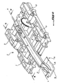
- the arrangement comprises a armrest itself 3 as shown in the Figure 1, for example with a width of 200 mm for a length of 300 mm.
- the armrest 3 is mounted on a support sole 4, moving between a position low back and a high advanced position, as we seen in Figure 3, through two pairs of rods, namely a pair of rods before 7 and a pair of rear connecting rods 8.
- Figure 3 shows these two armrest positions, the top position in lines full and the low position in phantom.
- the links 7 and 8 of the two pairs are arranged symmetrically by relative to the median longitudinal axis of the armrest 2 and are joined in rotation by a cross 9 and 10 respectively.
- each link device and cross member is associated with a spring 12 (FIG. 4) which is arranged substantially in the middle of the cross corresponding and designed to solicit the device to rods, and thus the armrest 3, from its position moved back low to its high advanced position.
- each spring is a spring of torsion whose axis is aligned with the axes of articulation of the pair of rods which are connected by the crosspiece on which the spring acts.
- the branches 13 and 14 of the spring are supported respectively on the sole 4 and the crosspiece 9 or 10.
- the armrest is locked in its lowered back position using a locking device 16 and unlockable by actuating the seat occupant corresponding.
- the control device for locking and unlocking features a rod control 17 (figure 4) displaceable substantially axially and an actuator 18 produced in the form of a bent lever with two substantially perpendicular arms to one another.
- the front end 19 of the lever serves control end while the rear end 21 is articulated at the corresponding end of the rod 17.
- the lever 18 is pivotally mounted at the junction of its two arms, namely at 24, to the structure of the armrest 3.
- the rod 17 and lever 18 are made in one part and the articulation zone 21 as well as the axis of pivoting of the lever are formed by flexible zones, for example weakened, of this control assembly.
- the pivot area 24 it is formed by a flexible, projecting tab, the end of which is fixed on the armrest.
- the sole 4 comprises a member 26 comprising a hook-shaped element locking 27.
- the control rod 17 has a recess 28 (figure 2) including the edge 29, end side free, engages, in the locked position of the armrest 3, under the hook 27 and disengages from it last when the rod 17 moves according to the arrow F1 ( Figure 4) under the effect of actuation of the end 19 of the lever 18 along arrow F2, the rod being arranged so as to move according to its axis.
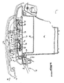
- the assembly formed by the armrest 3 and the sole 4 is pivotally mounted on the fixed structure of the vehicle, around an axis 34 located at the rear of the fixed structure 2.
- the sole 4 constitutes the pivoting cover of a storage bin 35 integrated into the fixed structure.
- Baccalaureat 35 is open by pivoting backwards, towards a substantially vertical position, from the sole.
- the sole is locked in its closed position tray 35 via a locking spout 36 engaging under a folded portion 37 of the edge upper front of the tank.
- the locking spout 36 makes projection at the elbow of an actuating lever angled 39, pallet-shaped, with the front end 40 constitutes the actuation part while the other end of the pallet, which extends substantially perpendicular to the actuating part, is articulated in 42 at the front of the sole 4.
- the articulation is made in the form of a flexible area weakened by the sole, the lever 39 being made in one piece with it.
- Figures 7 and 8 show that the storage bin 35 constitutes the pivoting cover of a storage space 44 also integrated into the fixed structure 2.
- the upper front edge of the tank is provided with a pallet-shaped control 46.
- the pallet is articulated at one end at 47 on the rim 48 of the tank.
- the free front end 49 of the pallet constitutes the actuation part.
- a tab 50 which ends with a hook 51. This hook, in the closed position of the volume 44, engages under an appropriate part 52 provided on the leading edge of the volume.
Landscapes
- Engineering & Computer Science (AREA)
- Aviation & Aerospace Engineering (AREA)
- Transportation (AREA)
- Mechanical Engineering (AREA)
- Seats For Vehicles (AREA)
- Passenger Equipment (AREA)
- Reciprocating, Oscillating Or Vibrating Motors (AREA)
- Steering Devices For Bicycles And Motorcycles (AREA)
Abstract
Description
L'invention concerne un agencement d'accoudoir selon le préambule de la revendication 1.The invention relates to an armrest arrangement according to the preamble of claim 1.
Des agencements d'accoudoir de ce type sont connus, par exemple, du document US-A-5 722 703.Armrest arrangements of this type are known, for example, from US-A-5,722,703.
L'invention a pour but de proposer un agencement d'accoudoir amélioré.The object of the invention is to propose an arrangement improved armrest.
Pour atteindre ce but, l'agencement d'accoudoir selon l'invention comporte les caractéristiques indiquées à la partie caractérisante de la revendication 1.To achieve this goal, the armrest arrangement according to the invention comprises the characteristics indicated in the characterizing part of claim 1.
Selon une réalisation avantageuse de l'invention, l'agencement d'accoudoir comporte des moyens de rappel de l'accoudoir dans sa position avancée haute et un dispositif de verrouillage et de déverrouillage de l'accoudoir dans sa position reculée basse, qui est pourvu d'une commande à tringle de déverrouillage.According to an advantageous embodiment of the invention, the arrangement armrest includes means for restoring the armrest in its high forward position and a device for locking and unlocking the armrest in its low back position, which is provided with a release rod.
Selon un autre mode de réalisation avantageux, la commande de déverrouillage comporte un élément de levier coudé pivotant, dont une extrémité sert d'extrémité d'actionnement tandis que l'autre extrémité sert de moyen de déplacement axial de la tringle de déverrouillage. According to another advantageous embodiment, the control of unlocking has a bent lever element swivel, one end of which acts as an end actuation while the other end serves as a means axial displacement of the release rod.
Selon un autre mode de réalisation préferé de l'invention, la semelle comporte un levier de verrouillage et de déverrouillage de la semelle dans sa position de fermeture du bac de rangement.According to another preferred embodiment of the invention, the sole has a locking lever and unlocking the sole in its position closing the storage bin.
Selon encore un autre mode de réalisation avantageux de l'invention, l'agencement comporte un levier de verrouillage et de déverrouillage du bac de rangement dans sa position de fermeture du volume de rangement.According to yet another advantageous embodiment of the invention, the arrangement includes a locking lever and unlocking the storage bin in its position storage volume closed.
L'invention sera mieux comprise et d'autres buts,
caractéristiques, détails et avantages de celle-ci
apparaítront plus clairement dans la description
explicative qui va suivre faite en référence aux dessins
schématiques annexés donnés uniquement à titre d'exemple
illustrant un mode de réalisation de l'invention et dans
lesquels :
L'agencement d'accoudoir selon l'invention, indiqué de
façon générale par la référence 1 (figure 3), est conçu
pour être disposé au niveau de l'axe du véhicule, entre
les deux sièges des passagers avant et est monté sur une
structure fixe 2.The armrest arrangement according to the invention, indicated by
generally by reference 1 (figure 3), is designed
to be positioned at the center line of the vehicle, between
the two front passenger seats and is mounted on a
Conformément aux figures, l'agencement comporte un
accoudoir proprement dit 3 tel que représenté sur la
figure 1, par exemple d'une largeur de 200 mm pour une
longueur de 300 mm. L'accoudoir 3 est monté sur une
semelle de support 4, se déplaçant entre une position
basse reculée et une position haute avancée, comme on le
voit sur la figure 3, par l'intermédiaire de deux paires
de biellettes, à savoir une paire de biellettes avant 7
et une paire de bielles arrière 8. La figure 3 montre ces
deux positions d'accoudoir, la position haute en traits
pleins et la position basse en traits mixtes. En se
référant à la figure 2, on constate que les biellettes 7
et 8 des deux paires sont disposées symétriquement par
rapport à l'axe longitudinal médian de l'accoudoir 2 et
sont solidarisées en rotation par une traverse
respectivement 9 et 10. A chaque dispositif de biellettes
et traverse est associé un ressort 12 (figure 4) qui est
disposé sensiblement au milieu de la traverse
correspondante et conçu pour solliciter le dispositif à
biellettes, et ainsi l'accoudoir 3, de sa position
reculée basse vers sa position avancée haute. Dans
l'exemple représenté, chaque ressort est un ressort de
torsion dont l'axe est aligné avec les axes
d'articulation de la paire de biellettes qui sont reliées
par la traverse sur laquelle agit le ressort. Les
branches 13 et 14 du ressort prennent appui
respectivement sur la semelle 4 et la traverse 9 ou 10.According to the figures, the arrangement comprises a
armrest itself 3 as shown in the
Figure 1, for example with a width of 200 mm for a
length of 300 mm. The
L'accoudoir est verrouillé dans sa position reculée basse
à l'aide d'un dispositif de verrouillage 16 et
déverrouillable par actionnement de l'occupant du siège
correspondant. A cette fin, le dispositif de commande de
verrouillage et de déverrouillage comporte une tringle de
commande 17 (figure 4) déplaçable sensiblement axialement
et un organe d'actionnement 18 réalisé sous la forme d'un
levier coudé à deux bras sensiblement perpendiculaires
l'un à l'autre. L'extrémité avant 19 du levier sert
d'extrémité de commande tandis que l'extrémité arrière 21
est articulée à l'extrémité correspondante de la tringle
de commande 17. The armrest is locked in its lowered back position
using a
Le levier 18 est monté pivotant au niveau de la jonction
de ses deux bras, à savoir en 24, à la structure de
l'accoudoir 3. Comme il ressort des figures, la tringle
de commande 17 et le levier 18 sont réalisés en une seule
pièce et la zone d'articulation 21 ainsi que l'axe de
pivotement du levier sont formés par des zones souples,
par exemple affaiblies, de cet ensemble de commande.
Concernant la zone de pivotement 24, elle est formée par
une patte en saillie, souple, dont l'extrémité est fixée
à l'accoudoir.The
Pour assurer le verrouillage de l'accoudoir à l'aide du
dispositif de commande 16, la semelle 4 comprend un
organe 26 comportant un élément en forme de crochet de
verrouillage 27. La tringle de commande 17 comporte un
évidement 28 (figure 2) dont le bord 29, côté extrémité
libre, s'engage, dans la position verrouillée de
l'accoudoir 3, sous le crochet 27 et se désengage de ce
dernier lorsque la tringle 17 se déplace suivant la
flèche F1 (figure 4) sous l'effet de l'actionnement de
l'extrémité 19 du levier 18 suivant la flèche F2, la
tringle étant disposée de façon à se déplacer suivant son
axe.To lock the armrest using the
Les biellettes 7 et 8, après le déverrouillage de
l'accoudoir, sont forcées par les ressorts 12 à pivoter
jusqu'au-delà de la position verticale vers une position
inclinée vers l'avant dans laquelle elles prennent appui
par un épaulement 31 sur une butée 32 montée fixe sur la
semelle 4 (figure 3).The
En se reportant aux figures 5 et 6, on constate que
l'ensemble formé par l'accoudoir 3 et la semelle 4 est
monté pivotant sur la structure fixe du véhicule, autour
d'un axe 34 situé à l'arrière de la structure fixe 2.
Ainsi, la semelle 4 constitue le couvercle pivotant d'un
bac de rangement 35 intégré à la structure fixe. Le bac
de rangement 35 est ouvert par pivotement en arrière,
vers une position sensiblement verticale, de la semelle.
La semelle est verrouillée dans sa position de fermeture
du bac 35 par l'intermédiaire d'un bec de verrouillage 36
venant en prise sous une portion repliée 37 du bord
supérieur avant du bac. Le bec de verrouillage 36 fait
saillie au niveau du coude d'un levier d'actionnement
coudé 39, en forme de palette, dont l'extrémité avant 40
constitue la partie d'actionnement tandis que l'autre
extrémité de la palette, qui s'étend sensiblement
perpendiculairement à la partie d'actionnement, est
articulée en 42 à l'avant de la semelle 4. L'articulation
est réalisée sous la forme d'une zone souple affaiblie de
la semelle, le levier 39 étant réalisé en une pièce avec
celle-ci.Referring to Figures 5 and 6, we see that
the assembly formed by the
Il ressort des figures 5 et 6 que, pour ouvrir le bac,
l'utilisateur actionne l'extrémité avant 40 de la palette
39 en direction de la flèche F3, ce qui assure le
désengagement du bec de verrouillage 36 de la contre-pièce
37 solidaire du bac. Par conséquent, l'ensemble
formé par la semelle et l'accoudoir est libre de pivoter
autour de l'axe 34 jusqu'à sa position d'ouverture du bac
représentée sur la figure 6. En se référant à la figure
1, on constate que la palette d'ouverture du bac est
située à côté de la palette centrale de verrouillage et
de déverrouillage de l'accoudoir.It appears from FIGS. 5 and 6 that, to open the tank,
the user operates the
Les figures 7 et 8 montrent que le bac de rangement 35
constitue le couvercle pivotant d'un volume de rangement
44 également intégré à la structure fixe 2. A cette fin,
le bord supérieur avant du bac est pourvu d'un organe de
commande en forme de palette 46. La palette est articulée
à une extrémité en 47 sur le rebord 48 du bac.
L'extrémité libre avant 49 de la palette constitue la
partie d'actionnement. Entre les deux extrémités de la
palette s'étend sensiblement verticalement vers le bas
une patte 50 qui se termine par un crochet 51. Ce
crochet, dans la position de fermeture du volume 44,
vient en prise sous une partie appropriée 52 prévue sur
le bord avant du volume.Figures 7 and 8 show that the
Comme il ressort des figures 7 et 8, lorsque
l'utilisateur exerce, par un doigt, une force en
direction de la flèche F4, le crochet 51 se désengage de
la partie 52 et l'ensemble formé par le bac, la semelle
et l'accoudoir est libre de pivoter, autour de l'axe 34,
jusqu'à sa position d'ouverture du volume de rangement
44. En se référant à la figure 1, on voit que la palette
46 est située à côté de la palette centrale
d'actionnement de l'accoudoir, sur le côté opposé à celui
où se trouve la palette d'actionnement 39 permettant
l'accès au bac de rangement.As shown in Figures 7 and 8, when
the user exerts, by a finger, a force in
direction of arrow F4,
Concernant le fonctionnement de l'agencement d'accoudoir
selon l'invention, il ressort déjà de la description qui
vient d'être faite. Il suffit donc de rappeler que
l'utilisateur peut remonter l'accoudoir dans sa position
haute avancée en actionnant la palette 18 suivant la
flèche F2 (figure 4). L'actionnement de la palette
entraíne la translation de la tringle de commande 17 et
le décrochage de celle-ci, en 27, de la semelle.
L'accoudoir se déplace alors suivant une trajectoire en
arc de cercle sous l'action des ressorts de torsion 12
jusqu'à venir en butée sur la semelle. L'accoudoir est
maintenu dans sa position haute sous l'effet des ressorts
et du fait que les biellettes, lors du pivotement, ont
dépassé la verticale. Par conséquent, un effort suivant
la flèche F5 (figure 4), c'est-à-dire sensiblement
verticalement, n'entraíne pas la descente de l'accoudoir.
Pour abaisser celui-ci, l'utilisateur doit fournir un
effort suivant la flèche F6, ce qui entraíne la descente
de l'accoudoir jusqu'au verrouillage de la tringle de
commande sous le crochet 27 de la semelle.Regarding the operation of the armrest arrangement
according to the invention, it is already apparent from the description which
has just been made. So just remember that
the user can raise the armrest to its position
advanced by operating the
Si l'utilisateur veut avoir accès au bac de rangement 35
ou au volume de rangement 44, il suffit d'actionner la
palette 39 ou la palette 46 et de faire pivoter en
arrière l'ensemble formé par la semelle et l'accoudoir ou
l'ensemble formé par le bac, la semelle et l'accoudoir.If the user wants to have access to the
Claims (6)
- An adjustable armrest arrangement for an automobile vehicle, of the type comprising a fixed lower part (2) which is provided with a base (4) on which the armrest (3) is mounted so that it can be displaced a between a lower position and an upper position via a connecting rod device (7, 8) of the parallelogram type, wherein the armrest (3) can be moved between a lower, retracted position and an upper, extended position, the supporting base (4) of the arm rest (3) being swivel-mounted on the fixed part (2) of the armrest arrangement and forming the swivelling cover of a storage box (35) which is incorporated in the fixed part (2), characterised in that the storage box (35) is swivel-mounted on the fixed part (2) of the armrest arrangement and constitutes the swivelling closure cover of a storage volume (44) which is incorporated in said fixed part (2).
- An arrangement according to claim 1, characterised in that it comprises means (12) for returning the armrest (3) to its upper, extended position and a device (16) for locking and unlocking the armrest (3) in its lower, retracted position, which device is provided with an unlocking rod ( 17) operating system.
- An arrangement according to claim 2, characterised in that the unlocking operating system comprises a pivoting elbow lever element (18), one end (19) of which serves as an operating end whilst the other end (21) serves as a means of axial displacement for the unlocking rod (17).
- An arrangement according to any one of claims 1 to 3, characterised in that the base (4) comprises a lever (39) for locking and unlocking the base (4) in its position of closure of the storage box (35).
- An arrangement according to any one of claims 1 to 4, characterised in that it comprises a lever (46) for locking and unlocking the storage box at (35) in its position of closure of the storage volume (44).
- An arrangement according to any one of claims 1 to 5, characterised in that in the upper, extended position of the armrest (3) the connecting rods (7, 8) occupy an inclined position and are supported on a stop (32) of the base (4) on the other side of the vertical with respect to their position in the lower situation of the armrest.
Applications Claiming Priority (2)
| Application Number | Priority Date | Filing Date | Title |
|---|---|---|---|
| FR9906642A FR2794080B1 (en) | 1999-05-26 | 1999-05-26 | ADJUSTABLE ARMREST ARRANGEMENT FOR A MOTOR VEHICLE |
| FR9906642 | 1999-05-26 |
Publications (2)
| Publication Number | Publication Date |
|---|---|
| EP1055552A1 EP1055552A1 (en) | 2000-11-29 |
| EP1055552B1 true EP1055552B1 (en) | 2004-10-06 |
Family
ID=9546015
Family Applications (1)
| Application Number | Title | Priority Date | Filing Date |
|---|---|---|---|
| EP00401427A Expired - Lifetime EP1055552B1 (en) | 1999-05-26 | 2000-05-23 | Adjustable armrest for motor vehicles |
Country Status (4)
| Country | Link |
|---|---|
| EP (1) | EP1055552B1 (en) |
| AT (1) | ATE278575T1 (en) |
| DE (1) | DE60014491T2 (en) |
| FR (1) | FR2794080B1 (en) |
Cited By (1)
| Publication number | Priority date | Publication date | Assignee | Title |
|---|---|---|---|---|
| EP4053018A1 (en) * | 2021-02-01 | 2022-09-07 | AMI Industries, Inc. | Extendable armrest with automatic retraction features |
Families Citing this family (5)
| Publication number | Priority date | Publication date | Assignee | Title |
|---|---|---|---|---|
| FR2897567B1 (en) * | 2006-02-21 | 2008-05-16 | Peugeot Citroen Automobiles Sa | ARMREST ASSEMBLY FOR A VEHICLE SEAT AND MOTOR VEHICLE COMPRISING AT LEAST ONE SUCH ASSEMBLY |
| JP2009536299A (en) | 2006-05-09 | 2009-10-08 | パルド, サンチャゴ カネド | Rotation control system |
| FR2901514B1 (en) | 2006-05-24 | 2009-02-13 | Renault Sas | ARMREST FOR MOTOR VEHICLE |
| DE102007013081C5 (en) | 2007-03-14 | 2023-08-31 | Grammer Aktiengesellschaft | Armrests, in particular for motor vehicles |
| DE102011117737A1 (en) * | 2011-11-05 | 2012-05-10 | Daimler Ag | Central console for motor vehicle, comprises openable lid and adjusting unit for adjusting and opening lid between its open position and its closed position |
Family Cites Families (5)
| Publication number | Priority date | Publication date | Assignee | Title |
|---|---|---|---|---|
| GB2194305B (en) * | 1986-08-08 | 1991-03-27 | Rolls Royce Motors Ltd | A mechanism for adjusting the position of an element |
| DE4225673A1 (en) * | 1992-08-04 | 1994-02-10 | Bayerische Motoren Werke Ag | Arrangement for housing electric auxiliaries in motor vehicle arm rest - is movably located with range of movement having two settings so that auxiliary unit e.g. electronic fax unit, in first position, is stowed completely in arm rest |
| FR2716786B1 (en) * | 1994-03-02 | 1996-05-03 | Faure France Bertrand | Improvements to folding armrests and seats fitted with such armrests. |
| US5722703A (en) * | 1995-07-27 | 1998-03-03 | Nifco Inc. | Pop-up mechanism |
| DE19542198C2 (en) * | 1995-11-13 | 2000-10-12 | Daimler Chrysler Ag | Armrest for a center console of a motor vehicle |
-
1999
- 1999-05-26 FR FR9906642A patent/FR2794080B1/en not_active Expired - Fee Related
-
2000
- 2000-05-23 EP EP00401427A patent/EP1055552B1/en not_active Expired - Lifetime
- 2000-05-23 AT AT00401427T patent/ATE278575T1/en not_active IP Right Cessation
- 2000-05-23 DE DE60014491T patent/DE60014491T2/en not_active Expired - Lifetime
Cited By (2)
| Publication number | Priority date | Publication date | Assignee | Title |
|---|---|---|---|---|
| EP4053018A1 (en) * | 2021-02-01 | 2022-09-07 | AMI Industries, Inc. | Extendable armrest with automatic retraction features |
| US11511862B2 (en) | 2021-02-01 | 2022-11-29 | Ami Industries, Inc. | Extendable armrest with automatic retraction features |
Also Published As
| Publication number | Publication date |
|---|---|
| DE60014491T2 (en) | 2005-10-20 |
| DE60014491D1 (en) | 2004-11-11 |
| FR2794080A1 (en) | 2000-12-01 |
| FR2794080B1 (en) | 2001-08-17 |
| EP1055552A1 (en) | 2000-11-29 |
| ATE278575T1 (en) | 2004-10-15 |
Similar Documents
| Publication | Publication Date | Title |
|---|---|---|
| EP0318355B1 (en) | Tilting apparatus for a lateral wing of a seat and bucket seat for automotive vehicles or the like having such an apparatus | |
| EP0228923A1 (en) | Convertible back seat | |
| EP0004484A1 (en) | Convertible seat for a motor vehicle | |
| FR2780351A1 (en) | VEHICLE SEAT WITH AUTOMATIC FRONT ANCHORAGE, AND VEHICLE COMPRISING SUCH A SEAT | |
| FR2797234A1 (en) | Slide mechanism, for vehicle seats, has bolt with control mechanism and locking mechanism, which is retained in position by anchorage mechanism, with independent operating finger | |
| FR2548106A1 (en) | AUXILIARY SEAT FOR VEHICLES | |
| FR2838391A1 (en) | DEVICE FOR FIXING A SEAT ON A VEHICLE FLOOR AND SEAT PROVIDED WITH SUCH A FIXING DEVICE | |
| EP0884219B1 (en) | Movable foot step for a vehicle | |
| EP1055552B1 (en) | Adjustable armrest for motor vehicles | |
| EP1461221A1 (en) | Device for opening and closing the hood of a folding-top convertible motor vehicle trunk | |
| FR2916392A1 (en) | Manual actuator for e.g. driver seat of two door sedan, has housing closed or opened towards bottom according to locking or unlocking position of actuator to guide seat belt fixed with bodywork of vehicle or to extract seat belt | |
| FR2696386A1 (en) | Folding rear passenger seat for motor vehicle - has seat cushion folding forward and lower back-rest dropping as seat back is folded to form load carrying floor | |
| EP1501694B1 (en) | Retractable package shelf system for convertible vehicle with folding roof | |
| FR2882538A1 (en) | SLIDER FOR VEHICLE SEAT AND SEAT COMPRISING SUCH A SLIDER | |
| EP1328416B1 (en) | Retractable roof for vehicle, comprising three longitudinal elements | |
| EP0404628B1 (en) | Seat with an adjustable and tiltable backrest | |
| EP1048514B1 (en) | Console for a motor vehicle interior | |
| EP0795435B1 (en) | Adjustable vehicle seat backrest | |
| EP0884218B1 (en) | Movable foot step for a vehicle | |
| FR2708550A1 (en) | Folding pushchair with adjustable seat height | |
| FR2696779A1 (en) | Automatic safety lock arrangement for slatted roll shutters - includes curved section which comes into contact with fixed end piece locking the shutter open | |
| EP0276186B1 (en) | Inertia-responsive vehicle seat latch mechanism | |
| FR2728136A1 (en) | Lawnmower grass cutting collection bin | |
| FR2775639A1 (en) | Hinge mechanism for fold away table used in motor vehicle | |
| EP1529681B1 (en) | Retractable seat, especially automotive vehicle seat and according vehicle. |
Legal Events
| Date | Code | Title | Description |
|---|---|---|---|
| PUAI | Public reference made under article 153(3) epc to a published international application that has entered the european phase |
Free format text: ORIGINAL CODE: 0009012 |
|
| AK | Designated contracting states |
Kind code of ref document: A1 Designated state(s): AT BE CH CY DE DK ES FI FR GB GR IE IT LI LU MC NL PT SE |
|
| AX | Request for extension of the european patent |
Free format text: AL;LT;LV;MK;RO;SI |
|
| 17P | Request for examination filed |
Effective date: 20010529 |
|
| AKX | Designation fees paid |
Free format text: AT BE CH CY DE DK ES FI FR GB GR IE IT LI LU MC NL PT SE |
|
| GRAP | Despatch of communication of intention to grant a patent |
Free format text: ORIGINAL CODE: EPIDOSNIGR1 |
|
| GRAS | Grant fee paid |
Free format text: ORIGINAL CODE: EPIDOSNIGR3 |
|
| GRAA | (expected) grant |
Free format text: ORIGINAL CODE: 0009210 |
|
| AK | Designated contracting states |
Kind code of ref document: B1 Designated state(s): AT BE CH CY DE DK ES FI FR GB GR IE IT LI LU MC NL PT SE |
|
| PG25 | Lapsed in a contracting state [announced via postgrant information from national office to epo] |
Ref country code: IE Free format text: LAPSE BECAUSE OF FAILURE TO SUBMIT A TRANSLATION OF THE DESCRIPTION OR TO PAY THE FEE WITHIN THE PRESCRIBED TIME-LIMIT Effective date: 20041006 Ref country code: NL Free format text: LAPSE BECAUSE OF FAILURE TO SUBMIT A TRANSLATION OF THE DESCRIPTION OR TO PAY THE FEE WITHIN THE PRESCRIBED TIME-LIMIT Effective date: 20041006 Ref country code: FI Free format text: LAPSE BECAUSE OF FAILURE TO SUBMIT A TRANSLATION OF THE DESCRIPTION OR TO PAY THE FEE WITHIN THE PRESCRIBED TIME-LIMIT Effective date: 20041006 Ref country code: AT Free format text: LAPSE BECAUSE OF FAILURE TO SUBMIT A TRANSLATION OF THE DESCRIPTION OR TO PAY THE FEE WITHIN THE PRESCRIBED TIME-LIMIT Effective date: 20041006 |
|
| REG | Reference to a national code |
Ref country code: GB Ref legal event code: FG4D Free format text: NOT ENGLISH |
|
| REG | Reference to a national code |
Ref country code: CH Ref legal event code: EP |
|
| REG | Reference to a national code |
Ref country code: IE Ref legal event code: FG4D Free format text: FRENCH |
|
| REF | Corresponds to: |
Ref document number: 60014491 Country of ref document: DE Date of ref document: 20041111 Kind code of ref document: P |
|
| PG25 | Lapsed in a contracting state [announced via postgrant information from national office to epo] |
Ref country code: SE Free format text: LAPSE BECAUSE OF FAILURE TO SUBMIT A TRANSLATION OF THE DESCRIPTION OR TO PAY THE FEE WITHIN THE PRESCRIBED TIME-LIMIT Effective date: 20050106 Ref country code: DK Free format text: LAPSE BECAUSE OF FAILURE TO SUBMIT A TRANSLATION OF THE DESCRIPTION OR TO PAY THE FEE WITHIN THE PRESCRIBED TIME-LIMIT Effective date: 20050106 Ref country code: GR Free format text: LAPSE BECAUSE OF FAILURE TO SUBMIT A TRANSLATION OF THE DESCRIPTION OR TO PAY THE FEE WITHIN THE PRESCRIBED TIME-LIMIT Effective date: 20050106 |
|
| PG25 | Lapsed in a contracting state [announced via postgrant information from national office to epo] |
Ref country code: ES Free format text: LAPSE BECAUSE OF FAILURE TO SUBMIT A TRANSLATION OF THE DESCRIPTION OR TO PAY THE FEE WITHIN THE PRESCRIBED TIME-LIMIT Effective date: 20050117 |
|
| GBT | Gb: translation of ep patent filed (gb section 77(6)(a)/1977) |
Effective date: 20050115 |
|
| NLV1 | Nl: lapsed or annulled due to failure to fulfill the requirements of art. 29p and 29m of the patents act | ||
| REG | Reference to a national code |
Ref country code: IE Ref legal event code: FD4D |
|
| PG25 | Lapsed in a contracting state [announced via postgrant information from national office to epo] |
Ref country code: LU Free format text: LAPSE BECAUSE OF NON-PAYMENT OF DUE FEES Effective date: 20050523 Ref country code: CY Free format text: LAPSE BECAUSE OF FAILURE TO SUBMIT A TRANSLATION OF THE DESCRIPTION OR TO PAY THE FEE WITHIN THE PRESCRIBED TIME-LIMIT Effective date: 20050523 |
|
| PG25 | Lapsed in a contracting state [announced via postgrant information from national office to epo] |
Ref country code: CH Free format text: LAPSE BECAUSE OF NON-PAYMENT OF DUE FEES Effective date: 20050531 Ref country code: MC Free format text: LAPSE BECAUSE OF NON-PAYMENT OF DUE FEES Effective date: 20050531 Ref country code: LI Free format text: LAPSE BECAUSE OF NON-PAYMENT OF DUE FEES Effective date: 20050531 Ref country code: BE Free format text: LAPSE BECAUSE OF NON-PAYMENT OF DUE FEES Effective date: 20050531 |
|
| PLBE | No opposition filed within time limit |
Free format text: ORIGINAL CODE: 0009261 |
|
| STAA | Information on the status of an ep patent application or granted ep patent |
Free format text: STATUS: NO OPPOSITION FILED WITHIN TIME LIMIT |
|
| 26N | No opposition filed |
Effective date: 20050707 |
|
| BERE | Be: lapsed |
Owner name: PEUGEOT CITROEN AUTOMOBILES SA Effective date: 20050531 |
|
| REG | Reference to a national code |
Ref country code: CH Ref legal event code: PL |
|
| REG | Reference to a national code |
Ref country code: GB Ref legal event code: 746 Effective date: 20070118 |
|
| BERE | Be: lapsed |
Owner name: S.A. *PEUGEOT CITROEN AUTOMOBILES Effective date: 20050531 |
|
| PG25 | Lapsed in a contracting state [announced via postgrant information from national office to epo] |
Ref country code: PT Free format text: LAPSE BECAUSE OF NON-PAYMENT OF DUE FEES Effective date: 20050306 |
|
| PGFP | Annual fee paid to national office [announced via postgrant information from national office to epo] |
Ref country code: GB Payment date: 20140425 Year of fee payment: 15 |
|
| PGFP | Annual fee paid to national office [announced via postgrant information from national office to epo] |
Ref country code: DE Payment date: 20140424 Year of fee payment: 15 Ref country code: IT Payment date: 20140424 Year of fee payment: 15 |
|
| PGFP | Annual fee paid to national office [announced via postgrant information from national office to epo] |
Ref country code: FR Payment date: 20140521 Year of fee payment: 15 |
|
| REG | Reference to a national code |
Ref country code: DE Ref legal event code: R119 Ref document number: 60014491 Country of ref document: DE |
|
| GBPC | Gb: european patent ceased through non-payment of renewal fee |
Effective date: 20150523 |
|
| PG25 | Lapsed in a contracting state [announced via postgrant information from national office to epo] |
Ref country code: IT Free format text: LAPSE BECAUSE OF NON-PAYMENT OF DUE FEES Effective date: 20150523 |
|
| REG | Reference to a national code |
Ref country code: FR Ref legal event code: ST Effective date: 20160129 |
|
| PG25 | Lapsed in a contracting state [announced via postgrant information from national office to epo] |
Ref country code: GB Free format text: LAPSE BECAUSE OF NON-PAYMENT OF DUE FEES Effective date: 20150523 Ref country code: DE Free format text: LAPSE BECAUSE OF NON-PAYMENT OF DUE FEES Effective date: 20151201 |
|
| PG25 | Lapsed in a contracting state [announced via postgrant information from national office to epo] |
Ref country code: FR Free format text: LAPSE BECAUSE OF NON-PAYMENT OF DUE FEES Effective date: 20150601 |