EP1055552B1 - Verstellbare Armlehne für Kraftfahrzeuge - Google Patents
Verstellbare Armlehne für Kraftfahrzeuge Download PDFInfo
- Publication number
- EP1055552B1 EP1055552B1 EP00401427A EP00401427A EP1055552B1 EP 1055552 B1 EP1055552 B1 EP 1055552B1 EP 00401427 A EP00401427 A EP 00401427A EP 00401427 A EP00401427 A EP 00401427A EP 1055552 B1 EP1055552 B1 EP 1055552B1
- Authority
- EP
- European Patent Office
- Prior art keywords
- armrest
- unlocking
- arrangement according
- arrangement
- locking
- Prior art date
- Legal status (The legal status is an assumption and is not a legal conclusion. Google has not performed a legal analysis and makes no representation as to the accuracy of the status listed.)
- Expired - Lifetime
Links
- 238000006073 displacement reaction Methods 0.000 claims description 2
- 240000008042 Zea mays Species 0.000 description 2
- 230000000694 effects Effects 0.000 description 2
Images


Classifications
-
- B—PERFORMING OPERATIONS; TRANSPORTING
- B60—VEHICLES IN GENERAL
- B60N—SEATS SPECIALLY ADAPTED FOR VEHICLES; VEHICLE PASSENGER ACCOMMODATION NOT OTHERWISE PROVIDED FOR
- B60N2/00—Seats specially adapted for vehicles; Arrangement or mounting of seats in vehicles
- B60N2/75—Arm-rests
- B60N2/763—Arm-rests adjustable
Definitions
- the invention relates to an armrest arrangement according to the preamble of claim 1.
- Armrest arrangements of this type are known, for example, from US-A-5,722,703.
- the object of the invention is to propose an arrangement improved armrest.
- the armrest arrangement according to the invention comprises the characteristics indicated in the characterizing part of claim 1.
- the arrangement armrest includes means for restoring the armrest in its high forward position and a device for locking and unlocking the armrest in its low back position, which is provided with a release rod.
- control of unlocking has a bent lever element swivel, one end of which acts as an end actuation while the other end serves as a means axial displacement of the release rod.
- the sole has a locking lever and unlocking the sole in its position closing the storage bin.
- the arrangement includes a locking lever and unlocking the storage bin in its position storage volume closed.
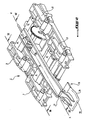
- the armrest arrangement according to the invention is designed to be positioned at the center line of the vehicle, between the two front passenger seats and is mounted on a fixed structure 2.
- the arrangement comprises a armrest itself 3 as shown in the Figure 1, for example with a width of 200 mm for a length of 300 mm.
- the armrest 3 is mounted on a support sole 4, moving between a position low back and a high advanced position, as we seen in Figure 3, through two pairs of rods, namely a pair of rods before 7 and a pair of rear connecting rods 8.
- Figure 3 shows these two armrest positions, the top position in lines full and the low position in phantom.
- the links 7 and 8 of the two pairs are arranged symmetrically by relative to the median longitudinal axis of the armrest 2 and are joined in rotation by a cross 9 and 10 respectively.
- each link device and cross member is associated with a spring 12 (FIG. 4) which is arranged substantially in the middle of the cross corresponding and designed to solicit the device to rods, and thus the armrest 3, from its position moved back low to its high advanced position.
- each spring is a spring of torsion whose axis is aligned with the axes of articulation of the pair of rods which are connected by the crosspiece on which the spring acts.
- the branches 13 and 14 of the spring are supported respectively on the sole 4 and the crosspiece 9 or 10.
- the armrest is locked in its lowered back position using a locking device 16 and unlockable by actuating the seat occupant corresponding.
- the control device for locking and unlocking features a rod control 17 (figure 4) displaceable substantially axially and an actuator 18 produced in the form of a bent lever with two substantially perpendicular arms to one another.
- the front end 19 of the lever serves control end while the rear end 21 is articulated at the corresponding end of the rod 17.
- the lever 18 is pivotally mounted at the junction of its two arms, namely at 24, to the structure of the armrest 3.
- the rod 17 and lever 18 are made in one part and the articulation zone 21 as well as the axis of pivoting of the lever are formed by flexible zones, for example weakened, of this control assembly.
- the pivot area 24 it is formed by a flexible, projecting tab, the end of which is fixed on the armrest.
- the sole 4 comprises a member 26 comprising a hook-shaped element locking 27.
- the control rod 17 has a recess 28 (figure 2) including the edge 29, end side free, engages, in the locked position of the armrest 3, under the hook 27 and disengages from it last when the rod 17 moves according to the arrow F1 ( Figure 4) under the effect of actuation of the end 19 of the lever 18 along arrow F2, the rod being arranged so as to move according to its axis.
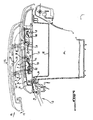
- the assembly formed by the armrest 3 and the sole 4 is pivotally mounted on the fixed structure of the vehicle, around an axis 34 located at the rear of the fixed structure 2.
- the sole 4 constitutes the pivoting cover of a storage bin 35 integrated into the fixed structure.
- Baccalaureat 35 is open by pivoting backwards, towards a substantially vertical position, from the sole.
- the sole is locked in its closed position tray 35 via a locking spout 36 engaging under a folded portion 37 of the edge upper front of the tank.
- the locking spout 36 makes projection at the elbow of an actuating lever angled 39, pallet-shaped, with the front end 40 constitutes the actuation part while the other end of the pallet, which extends substantially perpendicular to the actuating part, is articulated in 42 at the front of the sole 4.
- the articulation is made in the form of a flexible area weakened by the sole, the lever 39 being made in one piece with it.
- Figures 7 and 8 show that the storage bin 35 constitutes the pivoting cover of a storage space 44 also integrated into the fixed structure 2.
- the upper front edge of the tank is provided with a pallet-shaped control 46.
- the pallet is articulated at one end at 47 on the rim 48 of the tank.
- the free front end 49 of the pallet constitutes the actuation part.
- a tab 50 which ends with a hook 51. This hook, in the closed position of the volume 44, engages under an appropriate part 52 provided on the leading edge of the volume.
Landscapes
- Engineering & Computer Science (AREA)
- Aviation & Aerospace Engineering (AREA)
- Transportation (AREA)
- Mechanical Engineering (AREA)
- Seats For Vehicles (AREA)
- Passenger Equipment (AREA)
- Reciprocating, Oscillating Or Vibrating Motors (AREA)
- Steering Devices For Bicycles And Motorcycles (AREA)
Claims (6)
- Verstellbare Armlehnenanordnung für Kraftfahrzeuge, vom Typ mit einem festen Unterteil (2), das mit einer Sohle (4) versehen ist, auf der die Armlehne (3) montiert ist, welche zwischen einer unteren Stellung und einer oberen Stellung mittels einer parallelogrammartigen Schwenkarmvorrichtung (7, 8) verstellbar ist, wobei die Armlehne (3) zwischen einer unteren zurückgefahrenen Stellung und einer oberen vorgeschobenen Stellung beweglich ist, wobei die Tragsohle (4) der Armlehne (3) an dem festen Teil (2) der Armlehnenanordnung schwenkbeweglich gelagert ist und einen verschwenkbaren Deckel eines Ablagefachs (35) bildet, das im festen Teil (2) integriert ist, dadurch gekennzeichnet, dass das Ablagefach (35) am festen Teil (2) der Armlehnenanordnung schwenkbeweglich gelagert ist und den verschwenkbaren Deckel zum Verschließen eines Ablageraums (44) bildet, der im genannten festen Teil (2) integriert ist.
- Anordnung nach Anspruch 1, dadurch gekennzeichnet, dass sie Mittel (12) zum Zurückstellen der Armlehne (3) in ihre obere vorgeschobene Stellung und eine Vorrichtung (16) zum Ver- und Entriegeln der Armlehne (3) in ihrer unteren zurückgefahrenen Stellung enthält, die mit einer Entriegelungssteuerung mit Gestänge (17) versehen ist.
- Anordnung nach Anspruch 2, dadurch gekennzeichnet, dass die Entriegelungssteuerung ein verschwenkbares Winkelhebelelement (18) enthält, von dem ein Ende (19) als Betätigungsende dient, während das andere Ende (21) als Mittel zur axialen Verstellung des Entrieglungsgestänges (17) dient.
- Anordnung nach einem der Ansprüche 1 bis 3, dadurch gekennzeichnet, dass die Sohle (4) einen Hebel (39) zum Ver- und Entriegeln der Sohle (4) in ihrer Schließstellung zum Verschließen des Ablagefachs (35) enthält.
- Anordnung nach einem der Ansprüche 1 bis 4, dadurch gekennzeichnet, dass sie einen Hebel (46) zum Ver- und Entriegeln des Ablagefachs (35) in seiner Schließstellung zum Verschließen des Ablageraums (44) enthält.
- Anordnung nach einem der Ansprüche 1 bis 5, dadurch gekennzeichnet, dass die Schwenkarme (7, 8) in der oberen vorgeschobenen Stellung der Armlehne (3) eine geneigte Stellung in Anlage an einem Anschlag (32) der Sohle (4) auf der anderen Seite der Senkrechten bezüglich ihrer Position in der unteren Stellung der Armlehne einnehmen.
Applications Claiming Priority (2)
| Application Number | Priority Date | Filing Date | Title |
|---|---|---|---|
| FR9906642A FR2794080B1 (fr) | 1999-05-26 | 1999-05-26 | Agencement d'accoudoir reglable pour vehicule automobile |
| FR9906642 | 1999-05-26 |
Publications (2)
| Publication Number | Publication Date |
|---|---|
| EP1055552A1 EP1055552A1 (de) | 2000-11-29 |
| EP1055552B1 true EP1055552B1 (de) | 2004-10-06 |
Family
ID=9546015
Family Applications (1)
| Application Number | Title | Priority Date | Filing Date |
|---|---|---|---|
| EP00401427A Expired - Lifetime EP1055552B1 (de) | 1999-05-26 | 2000-05-23 | Verstellbare Armlehne für Kraftfahrzeuge |
Country Status (4)
| Country | Link |
|---|---|
| EP (1) | EP1055552B1 (de) |
| AT (1) | ATE278575T1 (de) |
| DE (1) | DE60014491T2 (de) |
| FR (1) | FR2794080B1 (de) |
Cited By (1)
| Publication number | Priority date | Publication date | Assignee | Title |
|---|---|---|---|---|
| EP4053018A1 (de) * | 2021-02-01 | 2022-09-07 | AMI Industries, Inc. | Ausziehbare armlehne mit automatischen einzugsmerkmalen |
Families Citing this family (5)
| Publication number | Priority date | Publication date | Assignee | Title |
|---|---|---|---|---|
| FR2897567B1 (fr) * | 2006-02-21 | 2008-05-16 | Peugeot Citroen Automobiles Sa | Ensemble d'accoudoir pour un siege de vehicule et vehicule automobile comportant au moins un tel ensemble |
| JP2009536299A (ja) | 2006-05-09 | 2009-10-08 | パルド, サンチャゴ カネド | 回動制御系 |
| FR2901514B1 (fr) | 2006-05-24 | 2009-02-13 | Renault Sas | Accoudoir pour vehicule automobile |
| DE102007013081C5 (de) | 2007-03-14 | 2023-08-31 | Grammer Aktiengesellschaft | Armlehne, insbesondere für Kraftfahrzeuge |
| DE102011117737A1 (de) * | 2011-11-05 | 2012-05-10 | Daimler Ag | Mittelkonsole |
Family Cites Families (5)
| Publication number | Priority date | Publication date | Assignee | Title |
|---|---|---|---|---|
| GB2194305B (en) * | 1986-08-08 | 1991-03-27 | Rolls Royce Motors Ltd | A mechanism for adjusting the position of an element |
| DE4225673A1 (de) * | 1992-08-04 | 1994-02-10 | Bayerische Motoren Werke Ag | Vorrichtung zum Anordnen von elektrischen Zusatzgeräten in Kraftfahrzeugen |
| FR2716786B1 (fr) * | 1994-03-02 | 1996-05-03 | Faure France Bertrand | Perfectionnements aux accoudoirs rabattables et aux sièges équipés de tels accoudoirs. |
| US5722703A (en) * | 1995-07-27 | 1998-03-03 | Nifco Inc. | Pop-up mechanism |
| DE19542198C2 (de) * | 1995-11-13 | 2000-10-12 | Daimler Chrysler Ag | Armauflage für eine Mittelkonsole eines Kraftfahrzeugs |
-
1999
- 1999-05-26 FR FR9906642A patent/FR2794080B1/fr not_active Expired - Fee Related
-
2000
- 2000-05-23 EP EP00401427A patent/EP1055552B1/de not_active Expired - Lifetime
- 2000-05-23 AT AT00401427T patent/ATE278575T1/de not_active IP Right Cessation
- 2000-05-23 DE DE60014491T patent/DE60014491T2/de not_active Expired - Lifetime
Cited By (2)
| Publication number | Priority date | Publication date | Assignee | Title |
|---|---|---|---|---|
| EP4053018A1 (de) * | 2021-02-01 | 2022-09-07 | AMI Industries, Inc. | Ausziehbare armlehne mit automatischen einzugsmerkmalen |
| US11511862B2 (en) | 2021-02-01 | 2022-11-29 | Ami Industries, Inc. | Extendable armrest with automatic retraction features |
Also Published As
| Publication number | Publication date |
|---|---|
| DE60014491T2 (de) | 2005-10-20 |
| DE60014491D1 (de) | 2004-11-11 |
| FR2794080A1 (fr) | 2000-12-01 |
| FR2794080B1 (fr) | 2001-08-17 |
| EP1055552A1 (de) | 2000-11-29 |
| ATE278575T1 (de) | 2004-10-15 |
Similar Documents
| Publication | Publication Date | Title |
|---|---|---|
| EP0318355B1 (de) | Umlegvorrichtung für die Seitenkanten eines Sitzes und Schalensitz für Kraftfahrzeuge oder ähnliches, welcher eine solche Vorrichtung aufweist | |
| EP0228923A1 (de) | Umwandelbarer Rücksitz | |
| EP0004484A1 (de) | Verwandelbarer Kraftfahrzeugsitz | |
| FR2780351A1 (fr) | Siege de vehicule a ancrage avant automatique, et vehicule comportant un tel siege | |
| FR2797234A1 (fr) | Glissiere pour siege de vehicule et siege comportant une telle glissiere | |
| FR2548106A1 (fr) | Siege auxiliaire pour vehicules | |
| FR2838391A1 (fr) | Dispositif de fixation d'un siege sur un plancher de vehicule et siege equipe d'un tel dispositif de fixation | |
| EP0884219B1 (de) | Bewegbare Trittstufe für ein Fahrzeug | |
| EP1055552B1 (de) | Verstellbare Armlehne für Kraftfahrzeuge | |
| EP1461221A1 (de) | Öffnungs- und verschlussvorrichtung für eine kofferrraumklappe eines cabriolet-fahrzeuges mit einem faltdach | |
| FR2916392A1 (fr) | Actionneur de deverrouillage de siege a guide de ceinture de securite integre, et dispositif de deverrouillage et siege correspondants | |
| FR2696386A1 (fr) | Siège escamotable pour véhicule automobile. | |
| EP1501694B1 (de) | Einziehbares ablagesystem für kabriolett mit faltdach | |
| FR2882538A1 (fr) | Glissiere pour siege de vehicule et siege comportant une telle glissiere | |
| EP1328416B1 (de) | Versenkbares fahrzeugdach mit drei längselementen | |
| EP0404628B1 (de) | Sitz mit verstellbarer und umlenkbarer Rückenlehne | |
| EP1048514B1 (de) | Konsole für einen Kraftfahrzeuginnenraum | |
| EP0795435B1 (de) | Einstellbare Rücklehne für Fahrzeugsitz | |
| EP0884218B1 (de) | Bewegbare Trittstufe für ein Fahrzeug | |
| FR2708550A1 (fr) | Poussette pliable et à hauteur d'assise réglable. | |
| FR2696779A1 (fr) | Verrou automatique de sécurité pour volets roulants. | |
| EP0276186B1 (de) | Vorrichtung zur Trägheitsverriegelung für Fahrzeugsitze | |
| FR2728136A1 (fr) | Bac de ramassage a coque de vidange pour tondeuse autoportee a support de bacs amovibles, et tondeuse comportant un tel bac | |
| FR2775639A1 (fr) | Mecanisme d'articulation pour tablette rabattable, notamment pour vehicule automobile | |
| EP1529681B1 (de) | Klappsitz, insbesondere Kraftfahrzeugsitz und entsprechendes Kraftfahrzeug. |
Legal Events
| Date | Code | Title | Description |
|---|---|---|---|
| PUAI | Public reference made under article 153(3) epc to a published international application that has entered the european phase |
Free format text: ORIGINAL CODE: 0009012 |
|
| AK | Designated contracting states |
Kind code of ref document: A1 Designated state(s): AT BE CH CY DE DK ES FI FR GB GR IE IT LI LU MC NL PT SE |
|
| AX | Request for extension of the european patent |
Free format text: AL;LT;LV;MK;RO;SI |
|
| 17P | Request for examination filed |
Effective date: 20010529 |
|
| AKX | Designation fees paid |
Free format text: AT BE CH CY DE DK ES FI FR GB GR IE IT LI LU MC NL PT SE |
|
| GRAP | Despatch of communication of intention to grant a patent |
Free format text: ORIGINAL CODE: EPIDOSNIGR1 |
|
| GRAS | Grant fee paid |
Free format text: ORIGINAL CODE: EPIDOSNIGR3 |
|
| GRAA | (expected) grant |
Free format text: ORIGINAL CODE: 0009210 |
|
| AK | Designated contracting states |
Kind code of ref document: B1 Designated state(s): AT BE CH CY DE DK ES FI FR GB GR IE IT LI LU MC NL PT SE |
|
| PG25 | Lapsed in a contracting state [announced via postgrant information from national office to epo] |
Ref country code: IE Free format text: LAPSE BECAUSE OF FAILURE TO SUBMIT A TRANSLATION OF THE DESCRIPTION OR TO PAY THE FEE WITHIN THE PRESCRIBED TIME-LIMIT Effective date: 20041006 Ref country code: NL Free format text: LAPSE BECAUSE OF FAILURE TO SUBMIT A TRANSLATION OF THE DESCRIPTION OR TO PAY THE FEE WITHIN THE PRESCRIBED TIME-LIMIT Effective date: 20041006 Ref country code: FI Free format text: LAPSE BECAUSE OF FAILURE TO SUBMIT A TRANSLATION OF THE DESCRIPTION OR TO PAY THE FEE WITHIN THE PRESCRIBED TIME-LIMIT Effective date: 20041006 Ref country code: AT Free format text: LAPSE BECAUSE OF FAILURE TO SUBMIT A TRANSLATION OF THE DESCRIPTION OR TO PAY THE FEE WITHIN THE PRESCRIBED TIME-LIMIT Effective date: 20041006 |
|
| REG | Reference to a national code |
Ref country code: GB Ref legal event code: FG4D Free format text: NOT ENGLISH |
|
| REG | Reference to a national code |
Ref country code: CH Ref legal event code: EP |
|
| REG | Reference to a national code |
Ref country code: IE Ref legal event code: FG4D Free format text: FRENCH |
|
| REF | Corresponds to: |
Ref document number: 60014491 Country of ref document: DE Date of ref document: 20041111 Kind code of ref document: P |
|
| PG25 | Lapsed in a contracting state [announced via postgrant information from national office to epo] |
Ref country code: SE Free format text: LAPSE BECAUSE OF FAILURE TO SUBMIT A TRANSLATION OF THE DESCRIPTION OR TO PAY THE FEE WITHIN THE PRESCRIBED TIME-LIMIT Effective date: 20050106 Ref country code: DK Free format text: LAPSE BECAUSE OF FAILURE TO SUBMIT A TRANSLATION OF THE DESCRIPTION OR TO PAY THE FEE WITHIN THE PRESCRIBED TIME-LIMIT Effective date: 20050106 Ref country code: GR Free format text: LAPSE BECAUSE OF FAILURE TO SUBMIT A TRANSLATION OF THE DESCRIPTION OR TO PAY THE FEE WITHIN THE PRESCRIBED TIME-LIMIT Effective date: 20050106 |
|
| PG25 | Lapsed in a contracting state [announced via postgrant information from national office to epo] |
Ref country code: ES Free format text: LAPSE BECAUSE OF FAILURE TO SUBMIT A TRANSLATION OF THE DESCRIPTION OR TO PAY THE FEE WITHIN THE PRESCRIBED TIME-LIMIT Effective date: 20050117 |
|
| GBT | Gb: translation of ep patent filed (gb section 77(6)(a)/1977) |
Effective date: 20050115 |
|
| NLV1 | Nl: lapsed or annulled due to failure to fulfill the requirements of art. 29p and 29m of the patents act | ||
| REG | Reference to a national code |
Ref country code: IE Ref legal event code: FD4D |
|
| PG25 | Lapsed in a contracting state [announced via postgrant information from national office to epo] |
Ref country code: LU Free format text: LAPSE BECAUSE OF NON-PAYMENT OF DUE FEES Effective date: 20050523 Ref country code: CY Free format text: LAPSE BECAUSE OF FAILURE TO SUBMIT A TRANSLATION OF THE DESCRIPTION OR TO PAY THE FEE WITHIN THE PRESCRIBED TIME-LIMIT Effective date: 20050523 |
|
| PG25 | Lapsed in a contracting state [announced via postgrant information from national office to epo] |
Ref country code: CH Free format text: LAPSE BECAUSE OF NON-PAYMENT OF DUE FEES Effective date: 20050531 Ref country code: MC Free format text: LAPSE BECAUSE OF NON-PAYMENT OF DUE FEES Effective date: 20050531 Ref country code: LI Free format text: LAPSE BECAUSE OF NON-PAYMENT OF DUE FEES Effective date: 20050531 Ref country code: BE Free format text: LAPSE BECAUSE OF NON-PAYMENT OF DUE FEES Effective date: 20050531 |
|
| PLBE | No opposition filed within time limit |
Free format text: ORIGINAL CODE: 0009261 |
|
| STAA | Information on the status of an ep patent application or granted ep patent |
Free format text: STATUS: NO OPPOSITION FILED WITHIN TIME LIMIT |
|
| 26N | No opposition filed |
Effective date: 20050707 |
|
| BERE | Be: lapsed |
Owner name: PEUGEOT CITROEN AUTOMOBILES SA Effective date: 20050531 |
|
| REG | Reference to a national code |
Ref country code: CH Ref legal event code: PL |
|
| REG | Reference to a national code |
Ref country code: GB Ref legal event code: 746 Effective date: 20070118 |
|
| BERE | Be: lapsed |
Owner name: S.A. *PEUGEOT CITROEN AUTOMOBILES Effective date: 20050531 |
|
| PG25 | Lapsed in a contracting state [announced via postgrant information from national office to epo] |
Ref country code: PT Free format text: LAPSE BECAUSE OF NON-PAYMENT OF DUE FEES Effective date: 20050306 |
|
| PGFP | Annual fee paid to national office [announced via postgrant information from national office to epo] |
Ref country code: GB Payment date: 20140425 Year of fee payment: 15 |
|
| PGFP | Annual fee paid to national office [announced via postgrant information from national office to epo] |
Ref country code: DE Payment date: 20140424 Year of fee payment: 15 Ref country code: IT Payment date: 20140424 Year of fee payment: 15 |
|
| PGFP | Annual fee paid to national office [announced via postgrant information from national office to epo] |
Ref country code: FR Payment date: 20140521 Year of fee payment: 15 |
|
| REG | Reference to a national code |
Ref country code: DE Ref legal event code: R119 Ref document number: 60014491 Country of ref document: DE |
|
| GBPC | Gb: european patent ceased through non-payment of renewal fee |
Effective date: 20150523 |
|
| PG25 | Lapsed in a contracting state [announced via postgrant information from national office to epo] |
Ref country code: IT Free format text: LAPSE BECAUSE OF NON-PAYMENT OF DUE FEES Effective date: 20150523 |
|
| REG | Reference to a national code |
Ref country code: FR Ref legal event code: ST Effective date: 20160129 |
|
| PG25 | Lapsed in a contracting state [announced via postgrant information from national office to epo] |
Ref country code: GB Free format text: LAPSE BECAUSE OF NON-PAYMENT OF DUE FEES Effective date: 20150523 Ref country code: DE Free format text: LAPSE BECAUSE OF NON-PAYMENT OF DUE FEES Effective date: 20151201 |
|
| PG25 | Lapsed in a contracting state [announced via postgrant information from national office to epo] |
Ref country code: FR Free format text: LAPSE BECAUSE OF NON-PAYMENT OF DUE FEES Effective date: 20150601 |