EP1055086B1 - Steuereinrichtung für einen brenner - Google Patents
Steuereinrichtung für einen brenner Download PDFInfo
- Publication number
- EP1055086B1 EP1055086B1 EP99966846A EP99966846A EP1055086B1 EP 1055086 B1 EP1055086 B1 EP 1055086B1 EP 99966846 A EP99966846 A EP 99966846A EP 99966846 A EP99966846 A EP 99966846A EP 1055086 B1 EP1055086 B1 EP 1055086B1
- Authority
- EP
- European Patent Office
- Prior art keywords
- valve
- switches
- control device
- valves
- switch
- Prior art date
- Legal status (The legal status is an assumption and is not a legal conclusion. Google has not performed a legal analysis and makes no representation as to the accuracy of the status listed.)
- Expired - Lifetime
Links
Images
Classifications
-
- F—MECHANICAL ENGINEERING; LIGHTING; HEATING; WEAPONS; BLASTING
- F23—COMBUSTION APPARATUS; COMBUSTION PROCESSES
- F23N—REGULATING OR CONTROLLING COMBUSTION
- F23N5/00—Systems for controlling combustion
- F23N5/24—Preventing development of abnormal or undesired conditions, i.e. safety arrangements
- F23N5/242—Preventing development of abnormal or undesired conditions, i.e. safety arrangements using electronic means
-
- F—MECHANICAL ENGINEERING; LIGHTING; HEATING; WEAPONS; BLASTING
- F23—COMBUSTION APPARATUS; COMBUSTION PROCESSES
- F23N—REGULATING OR CONTROLLING COMBUSTION
- F23N2223/00—Signal processing; Details thereof
- F23N2223/08—Microprocessor; Microcomputer
-
- F—MECHANICAL ENGINEERING; LIGHTING; HEATING; WEAPONS; BLASTING
- F23—COMBUSTION APPARATUS; COMBUSTION PROCESSES
- F23N—REGULATING OR CONTROLLING COMBUSTION
- F23N2235/00—Valves, nozzles or pumps
- F23N2235/12—Fuel valves
- F23N2235/14—Fuel valves electromagnetically operated
-
- F—MECHANICAL ENGINEERING; LIGHTING; HEATING; WEAPONS; BLASTING
- F23—COMBUSTION APPARATUS; COMBUSTION PROCESSES
- F23N—REGULATING OR CONTROLLING COMBUSTION
- F23N2235/00—Valves, nozzles or pumps
- F23N2235/12—Fuel valves
- F23N2235/18—Groups of two or more valves
Definitions
- Such a control device for a burner is described in DE 195 07 071 and DE 195 07 073 A1.
- the burner is a Gas burner, and in the gas path two valves are arranged in series, the each controlled by two semiconductor switches of different construction, around each of the two valves with both one and the other Switch off semiconductor switch, d. H. to be able to block the gas path.
- the switching reliability is increased.
- Both switches of a valve is assigned to a control unit and the two switches of the other valve is a separate second control unit assigned.
- the control units receive data on the switching state of assigned valves and can thereby determine that the switch on a have corresponding control signal actually blocked the valves or Not.
- the safety of the control device is increased by the fact that the two switches each valve are differently constructed semiconductor switches, and continue in that the two switches per valve have different ones Control logic can be controlled. Due to the different structure the semiconductor switch and / or the control logic is the probability of failure significantly reduced.
- the functional reliability is further increased by the fact that all switches cyclically be checked for their switching behavior.
Landscapes
- Engineering & Computer Science (AREA)
- Chemical & Material Sciences (AREA)
- Combustion & Propulsion (AREA)
- Mechanical Engineering (AREA)
- General Engineering & Computer Science (AREA)
- Feeding And Controlling Fuel (AREA)
- Regulation And Control Of Combustion (AREA)
Description
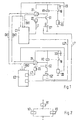
- Fig. 1
- einen schematischen Schaltplan einer Steuereinrichtung und
- Fig. 2
- ein Beispiel für eine Gaszuführung zu einem Brenner.
Claims (4)
- Steuereinrichtung für einen Brenner mit zwei in Reihe zueinander in einem Zuführzweig für ein Brennmedium angeordneten Ventilen (V1, V2) und mindestens zwei in Reihe zueinander angeordneten Schaltern (S1, S1'; S2, S2') pro Ventil (V1, V2), die von zugeordneten Steuereinheiten (C1, C2) zum Schließen und Öffnen angesteuert werden, wobei den beiden Steuereinheiten (C1, C2) Daten (DV1, DV2) über einen Schaltzustand der Ventile (V1, V2) zugeführt sind,
dadurch gekennzeichnet,
das die erste Steuereinheit (C1) sowohl zur Ansteuerung eines der beiden Schalter (S1) des ersten Ventils (V1) als auch eines der beiden Schalter (S2') des zweiten Ventils (V2) und die zweite Steuereinheit (C2) zur Ansteuerung des anderen Schalters (S1') des ersten Ventils (V1) und des anderen Schalters (S2) des zweiten Ventils (V2) ausgebildet ist und dass den beiden Steuereinheiten (C1, C2) Daten über den Schaltzustand sowohl des einen Ventils als auch des anderen Ventils zugeführt sind. - Steuereinrichtung nach Anspruch 1,
dadurch gekennzeichnet, dass die beiden Schalter (S1, S1' bzw. S2, S2') pro Ventil (V1 bzw. V2) jeweils unterschiedlich aufgebaute Halbleiterschalter sind. - Steuereinrichtung nach einem der vorherigen Ansprüche,
dadurch gekennzeichnet, dass die beiden Schalter (S1, S1' bzw. S2, S2') pro Ventil (V1 bzw. V2) über jeweils verschiedene Ansteuerlogiken angesteuert werden. - Steuereinrichtung nach einem der vorherigen Ansprüche,
dadurch gekennzeichnet, dass alle Schalter (S1, S1', S2, S2') zyklisch auf ihr Schaltverhalten überprüft werden.
Applications Claiming Priority (3)
| Application Number | Priority Date | Filing Date | Title |
|---|---|---|---|
| DE19856954 | 1998-12-10 | ||
| DE19856954A DE19856954C1 (de) | 1998-12-10 | 1998-12-10 | Steuereinrichtung für einen Brenner |
| PCT/DE1999/003919 WO2000034716A1 (de) | 1998-12-10 | 1999-12-08 | Steuereinrichtung für einen brenner |
Publications (2)
| Publication Number | Publication Date |
|---|---|
| EP1055086A1 EP1055086A1 (de) | 2000-11-29 |
| EP1055086B1 true EP1055086B1 (de) | 2003-03-19 |
Family
ID=7890603
Family Applications (1)
| Application Number | Title | Priority Date | Filing Date |
|---|---|---|---|
| EP99966846A Expired - Lifetime EP1055086B1 (de) | 1998-12-10 | 1999-12-08 | Steuereinrichtung für einen brenner |
Country Status (6)
| Country | Link |
|---|---|
| EP (1) | EP1055086B1 (de) |
| BR (1) | BR9907803A (de) |
| DE (2) | DE19856954C1 (de) |
| ES (1) | ES2195657T3 (de) |
| PL (1) | PL342217A1 (de) |
| WO (1) | WO2000034716A1 (de) |
Families Citing this family (1)
| Publication number | Priority date | Publication date | Assignee | Title |
|---|---|---|---|---|
| DE10321764B4 (de) * | 2003-05-15 | 2005-04-28 | Bbt Thermotechnik Gmbh | Verfahren zur Ansteuerung eines Sicherheitsrelais in einem Feuerungsautomaten |
Family Cites Families (5)
| Publication number | Priority date | Publication date | Assignee | Title |
|---|---|---|---|---|
| EP0497147A3 (en) * | 1991-01-28 | 1993-05-05 | Siemens Aktiengesellschaft | Redundant automation system |
| DE9310451U1 (de) * | 1993-03-05 | 1994-06-30 | Landis & Gyr Business Support | Steuer- bzw. Regeleinrichtung für Gas-Feuerungsautomaten von Heizungsanlagen |
| DE4342903A1 (de) * | 1993-12-16 | 1995-06-22 | Bosch Gmbh Robert | Vorrichtung zum Überwachen wenigstens einer sicherheitsrelevanten Funktion eines Gerätes |
| DE19507073A1 (de) * | 1995-03-01 | 1996-09-05 | Bosch Gmbh Robert | Schaltung zum Ein- und Ausschalten einer elektrischen Last |
| DE19507071A1 (de) * | 1995-03-01 | 1996-09-05 | Bosch Gmbh Robert | Schaltung zum Ein- und Ausschalten einer elektrischen Last |
-
1998
- 1998-12-10 DE DE19856954A patent/DE19856954C1/de not_active Expired - Fee Related
-
1999
- 1999-12-08 ES ES99966846T patent/ES2195657T3/es not_active Expired - Lifetime
- 1999-12-08 WO PCT/DE1999/003919 patent/WO2000034716A1/de active IP Right Grant
- 1999-12-08 DE DE59904625T patent/DE59904625D1/de not_active Expired - Lifetime
- 1999-12-08 PL PL99342217A patent/PL342217A1/xx unknown
- 1999-12-08 BR BR9907803-1A patent/BR9907803A/pt unknown
- 1999-12-08 EP EP99966846A patent/EP1055086B1/de not_active Expired - Lifetime
Also Published As
| Publication number | Publication date |
|---|---|
| ES2195657T3 (es) | 2003-12-01 |
| BR9907803A (pt) | 2000-10-17 |
| DE19856954C1 (de) | 2000-05-11 |
| EP1055086A1 (de) | 2000-11-29 |
| WO2000034716A1 (de) | 2000-06-15 |
| DE59904625D1 (de) | 2003-04-24 |
| PL342217A1 (en) | 2001-05-21 |
Similar Documents
| Publication | Publication Date | Title |
|---|---|---|
| EP1493064B2 (de) | Vorrichtung zum fehlersicheren abschalten eines elektrischen verbrauchers, insbesondere in industriellen produktionsanlagen | |
| DE69936255T2 (de) | Elektromagnet- vorrichtung mit zwei von drei elektromagneten die immer betätigt sind | |
| EP1277011B2 (de) | Modulares sicherheitsschaltgeräte-system | |
| EP1269274B2 (de) | Sicherheitsschaltgerät und verfahren zur einstellung eines betriebsmodus eines sicherheitsschaltgeräts | |
| EP0963594B1 (de) | Modulares sicherheitsschaltgerät | |
| DE2444455C3 (de) | Steuersystem für eine Brenneranlage | |
| DE10351873B4 (de) | Vorrichtung und Verfahren zum fehlersicheren Abschalten eines induktiven Verbrauchers | |
| DE4113959A1 (de) | Ueberwachungseinrichtung | |
| EP1055086B1 (de) | Steuereinrichtung für einen brenner | |
| DE3522220C2 (de) | Schaltungsanordnung zur sicheren Ansteuerung von Stellelementen eines Prozesses | |
| CH686200A5 (de) | Wasser-Durchlauferhitzer. | |
| EP0948015A2 (de) | Elektro-Hausgerät, insbesondere elektrischer Durchlauferhitzer | |
| EP1081431B1 (de) | Steuergerät für wärmetechnische Anlagen | |
| WO2002099547A1 (de) | Vorrichtung zur sicheren signalerzeugung | |
| DE3919558C2 (de) | ||
| EP1141633B1 (de) | Steuereinrichtung für einen brenner | |
| EP1273500B1 (de) | Steuerung für ein Relais | |
| DE3013061C2 (de) | Verfahren und Vorrichtung zum Betrieb redundanter Steuerungseinrichtungen | |
| DE2318072C3 (de) | System zur Überwachung und Fehlermeldung in sicherheitstechnischen Anlagen | |
| DE3532017A1 (de) | Sicherheitsschaltung zum steuern kritischer lasten von gas- oder oelbrennern | |
| DE3206082C2 (de) | Fehlersichere Anordnung zur Verknüpfung der Betriebszustandsmeldungen von Signallampen | |
| EP1477739A2 (de) | Verfahren zur Ansteuerung eines Sicherheitsrelais in einem Feuerungsautomaten | |
| DE3022077C2 (de) | ||
| DE1513297C (de) | ||
| CH673732A5 (de) |
Legal Events
| Date | Code | Title | Description |
|---|---|---|---|
| PUAI | Public reference made under article 153(3) epc to a published international application that has entered the european phase |
Free format text: ORIGINAL CODE: 0009012 |
|
| AK | Designated contracting states |
Kind code of ref document: A1 Designated state(s): AT BE CH CY DE DK ES FI FR GB GR IE IT LI LU MC NL PT SE |
|
| 17P | Request for examination filed |
Effective date: 20001215 |
|
| GRAG | Despatch of communication of intention to grant |
Free format text: ORIGINAL CODE: EPIDOS AGRA |
|
| 17Q | First examination report despatched |
Effective date: 20020619 |
|
| GRAG | Despatch of communication of intention to grant |
Free format text: ORIGINAL CODE: EPIDOS AGRA |
|
| GRAH | Despatch of communication of intention to grant a patent |
Free format text: ORIGINAL CODE: EPIDOS IGRA |
|
| GRAH | Despatch of communication of intention to grant a patent |
Free format text: ORIGINAL CODE: EPIDOS IGRA |
|
| GRAA | (expected) grant |
Free format text: ORIGINAL CODE: 0009210 |
|
| AK | Designated contracting states |
Designated state(s): DE ES FR GB IT |
|
| REG | Reference to a national code |
Ref country code: GB Ref legal event code: FG4D Free format text: NOT ENGLISH |
|
| REF | Corresponds to: |
Ref document number: 59904625 Country of ref document: DE Date of ref document: 20030424 Kind code of ref document: P |
|
| GBT | Gb: translation of ep patent filed (gb section 77(6)(a)/1977) | ||
| ET | Fr: translation filed | ||
| PLBE | No opposition filed within time limit |
Free format text: ORIGINAL CODE: 0009261 |
|
| STAA | Information on the status of an ep patent application or granted ep patent |
Free format text: STATUS: NO OPPOSITION FILED WITHIN TIME LIMIT |
|
| 26N | No opposition filed |
Effective date: 20031222 |
|
| PGFP | Annual fee paid to national office [announced via postgrant information from national office to epo] |
Ref country code: ES Payment date: 20141215 Year of fee payment: 16 Ref country code: GB Payment date: 20141216 Year of fee payment: 16 |
|
| PGFP | Annual fee paid to national office [announced via postgrant information from national office to epo] |
Ref country code: FR Payment date: 20141212 Year of fee payment: 16 |
|
| PGFP | Annual fee paid to national office [announced via postgrant information from national office to epo] |
Ref country code: IT Payment date: 20141219 Year of fee payment: 16 |
|
| REG | Reference to a national code |
Ref country code: DE Ref legal event code: R084 Ref document number: 59904625 Country of ref document: DE |
|
| REG | Reference to a national code |
Ref country code: DE Ref legal event code: R084 Ref document number: 59904625 Country of ref document: DE Effective date: 20150423 |
|
| GBPC | Gb: european patent ceased through non-payment of renewal fee |
Effective date: 20151208 |
|
| REG | Reference to a national code |
Ref country code: FR Ref legal event code: ST Effective date: 20160831 |
|
| PG25 | Lapsed in a contracting state [announced via postgrant information from national office to epo] |
Ref country code: GB Free format text: LAPSE BECAUSE OF NON-PAYMENT OF DUE FEES Effective date: 20151208 |
|
| PG25 | Lapsed in a contracting state [announced via postgrant information from national office to epo] |
Ref country code: FR Free format text: LAPSE BECAUSE OF NON-PAYMENT OF DUE FEES Effective date: 20151231 |
|
| PG25 | Lapsed in a contracting state [announced via postgrant information from national office to epo] |
Ref country code: IT Free format text: LAPSE BECAUSE OF NON-PAYMENT OF DUE FEES Effective date: 20151208 |
|
| REG | Reference to a national code |
Ref country code: ES Ref legal event code: FD2A Effective date: 20170127 |
|
| PG25 | Lapsed in a contracting state [announced via postgrant information from national office to epo] |
Ref country code: ES Free format text: LAPSE BECAUSE OF NON-PAYMENT OF DUE FEES Effective date: 20151209 |
|
| PGFP | Annual fee paid to national office [announced via postgrant information from national office to epo] |
Ref country code: DE Payment date: 20190221 Year of fee payment: 20 |
|
| REG | Reference to a national code |
Ref country code: DE Ref legal event code: R071 Ref document number: 59904625 Country of ref document: DE |