EP1055085B1 - Internal geometry shape design for venturi tube-like gas-air mixing valve - Google Patents
Internal geometry shape design for venturi tube-like gas-air mixing valve Download PDFInfo
- Publication number
- EP1055085B1 EP1055085B1 EP98960420A EP98960420A EP1055085B1 EP 1055085 B1 EP1055085 B1 EP 1055085B1 EP 98960420 A EP98960420 A EP 98960420A EP 98960420 A EP98960420 A EP 98960420A EP 1055085 B1 EP1055085 B1 EP 1055085B1
- Authority
- EP
- European Patent Office
- Prior art keywords
- valve
- gas
- air
- inlet
- throttle
- Prior art date
- Legal status (The legal status is an assumption and is not a legal conclusion. Google has not performed a legal analysis and makes no representation as to the accuracy of the status listed.)
- Expired - Lifetime
Links
Images

Classifications
-
- F—MECHANICAL ENGINEERING; LIGHTING; HEATING; WEAPONS; BLASTING
- F23—COMBUSTION APPARATUS; COMBUSTION PROCESSES
- F23D—BURNERS
- F23D14/00—Burners for combustion of a gas, e.g. of a gas stored under pressure as a liquid
- F23D14/46—Details
- F23D14/62—Mixing devices; Mixing tubes
- F23D14/64—Mixing devices; Mixing tubes with injectors
-
- Y—GENERAL TAGGING OF NEW TECHNOLOGICAL DEVELOPMENTS; GENERAL TAGGING OF CROSS-SECTIONAL TECHNOLOGIES SPANNING OVER SEVERAL SECTIONS OF THE IPC; TECHNICAL SUBJECTS COVERED BY FORMER USPC CROSS-REFERENCE ART COLLECTIONS [XRACs] AND DIGESTS
- Y10—TECHNICAL SUBJECTS COVERED BY FORMER USPC
- Y10T—TECHNICAL SUBJECTS COVERED BY FORMER US CLASSIFICATION
- Y10T137/00—Fluid handling
- Y10T137/8593—Systems
- Y10T137/87571—Multiple inlet with single outlet
- Y10T137/87587—Combining by aspiration
Definitions
- the present invention relates to a multiple capacity Venturi gas-air mixing valve. More particularly the invention relates to an internal geometrical shape design for a tube-like gas-air mixing valve.
- the invention relates generally to a multiple capacity gas-air mixing valve including an internal geometrical shape design for a tube-like gas-air mixing valve.
- the output of the valve is combusted in a downstream combustion device such as a boiler.
- U.S. Patent No. 4,845,952 and U.S. Patent No. 4,966,001 also use tubes for mixing fuel by placing the tubes in the air flow path. These patents employ a multiple-venture tube pre-mix apparatus.
- Hu U.S. Patent No. 5,402,633 discloses a premix gas nozzle with a longitudinal tangential entrance slots.
- Kesseli U.S. Patent No. 5,450,724 uses a plurality of mixing channels that are oriented to impart a swirling motion to the mixed combustion air and fuel.
- Booz U.S. Patent No. 5,140,820 relates to a carburation system for small scale engines but is stated to be usable in larger engines and even auxiliary power units. It does not disclose a valve means.
- Reed et al U.S. Patent No. 3,684,189 comprises a metal burner tip that is welded to a standard pipe. No replacement parts are contemplated, nor is the use of adjustable parts. Also, neither the inlet nor the outlet have the configuration found to be superior in the present invention.
- valve parts were designed by experience, using trial and error methods that led to high design expense or less than optimum results.
- inlet and outlet parts which are made from plastic and mounted in an aluminum body, had to be completely manufactured and tested. This made the design process very slow and quite expensive.
- efficiency of the developed shape was not always satisfactory for the many different end uses.
- a pressure drop may range from less than 350 Pascals to more than 550 Pascals.
- desired air capacities range from 18 to 66 cubic meters per hour (m 3 /h) and the accompanying gas capacities for that range of air flow.
- Another advantage would be if the outlet part of the valve would be configured to maximize the overall operation of the valve.
- the present invention provides an internal geometrical shape design for a Venture tube-like gas-air mixing valve.
- the output of the valve is combusted in a downstream combustion device such as a boiler.
- the valve of the present invention is selected to operate with such a boiler or other combustion device, which device determines the range of gas and air flow rates needed to operate efficiently over the operating range of the boiler. Once these parameters are selected, the valve itself is determined by the method of this invention.
- the present invention involves an internal geometrical shape design for a tube-like gas-air mixing valve.
- This invention not only enables one to achieve optimal computer provided efficiency, but also is used to facilitate integration of a plastic inlet part with the aluminum body which is unchanged over a range of various valve capacities and pressure drops.
- the inlet part of the valve is made by extrusion from an appropriate plastic material.
- the same metal valve body is used for a whole variety of mixing valves by changing only relatively simply manufactured plastic parts designed for certain gas-air mixing parameters.
- a gas-air mixing valve of the present invention has an adjustable air inlet that is fixed by adjusting the radius of the throttle admitting air to the mixing portion of the valve.
- the gas inlet is also adjusted, based on the desired operating conditions of the valve.
- the internal geometry shape for directing the flow of air and gas in the valve defines that flow.
- the inlet part is formed with a more permanent body part, such as one made from aluminum, and a replaceable molded part, preferably made from plastic.
- the first body part has an inlet surface centered about a central axis defined by a concave surface having a first circular cross section.
- the replaceable molded part has a composite surface defined by conical surface having a linear cross section and further defined in part by a convex surface having a second circular cross section forming the throttle.
- the mixing valve of this invention functions by adjusting the proportion of gas and air using the principles of venturi action.
- convex and concave as used above are, of course, surfaces of the cross section with respect to said central axis.
- the replaceable outlet part of the valve has a composite outlet surface defined by a first conical surface extending from the above mentioned second circular cross section of the first body part to a second convex surface on the outlet part, such that the second convex surface acts as a flared surface for the outlet of the valve.
- the specifics of the valve such as air throttle opening (which fixes the air volume) and gas inlet size (which fixes the gas volume) may be optimized for each application of the valve.
- the only part that needs to be adjusted for the completed valve is the replaceable molded plastic part.
- the invention involves an internal geometric shape for a component of a gas-air mixing valve.
- the valve itself is based on the principle and includes a structure that can be made with a simple fabrication process while maintaining the postulated characteristics of the valve.
- the mixing valve has certain required characteristics relevant to air discharge, gas discharge, gas/air volume proportions for different fan loads, pressure drops along the valve, modulation band and the maximum angle of the outlet part.
- preferred pressure drops are 350, 450 and 550 Pascals, respectively.
- the air capacities are within the range of 18-66 cubic meters per hour (m 3 /h) which are accompanied by the respective gas capacities. Of course, other pressure drop ranges and air capacities will be selected for other boilers, fan, and system variables.
- the general inner shape profile is designed in order to achieve the most important valve characteristics, which are gas/air volume proportions for different fan loads, and the modulation band, and these strongly determine overall valve efficiency.
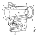
- FIG. 1 illustrates a portion of an integrated gas/air control safety system with fan and a Valve 10 generally, having an inlet 11, a discharge end 13 that delivers the appropriate air/gas mixture to a boiler or other combustion system (not shown) in the optimum quantities.
- the inlet 11 includes a metal portion 15 and a replaceable plastic molded parts 17 and 23, all described in detail below.
- Metal portion 15 forms concave surface 19.
- Molded part 23 forms a convex surface 21 forming part of the throttle 23.
- Molded part 17 fits between surfaces 19 and 21.
- Discharge end 13 includes a conical surface 25 extending from first convex surface 21 to a second convex surface 27 at the outlet end 29 of discharge 13.
- the remaining parts of valve 10 is a conventional gas supply unit 30 for supplying gas to the gas inlet described below and controlled by throttle 23.
- Valve 10 is centered about an axis 31.
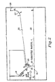
- First concave surface 19 forms the first surface encountered by inlet air entering in the direction of arrow 33 in Fig. 2.
- Surface 19 is a circular segment having a center at Q2 and defining an arc between points P1 and P2, and a straight portion between P2 and P3. In the present embodiment, this arc was calculated to be about 80°.
- first convex surface 21 is a circular segment having a center at Q1 and defining an arc between points S1 and S2. In the present embodiment, this arc was calculated to be about 70°.
- the region between P3 and S1 is conical surface 25 of molded part 17.
- Curved surface 21 is also the outside of throttle 23, and throttle 23 is moveable to vary the gas inlet slot 35, which is the gap between throttle 23 and conical surface 25, to permit gas to enter via the forces in the direction of arrow 37 in Fig. 3.
- Gas slot s is the distance between points S3 and S4, as shown in Fig. 3.
- the metal part 15 can be standardized once the parameters of the boiler system are established.
- the only variable for a complete family of valves would be the molded plastic parts 17, 23, 25, and 27.
- Conical surface 25 is at an angle with respect to the axis 31 of the valve.
- the angle surface 25 makes with the axis 31 is about 42°.
- the shape profile of the inlet part is a combination of two circular surfaces and one cylindrical surface while the outlet part is a combination of one conical surface and another surface which is described pointwise and smoothed by splines.
- Figs. 2 and 3 are typical asymmetrical schematics developed for the preferred embodiment.
- valves it is not possible, presently, to calculate the exact air dynamics for premixing air and gas in these systems using valves to achieve the optimal proportion of gas and air.
- the amount of gas/air mixture being drawn into the system will vary, because of process needs and the like, to that the fan will operate at different speeds and capacities.
- the valve therefore must also be variable in order to provide a constant proportion of gas and air. This is done by adjusting the air flow via throttle radius 37, shown in Fig. 2, and the gas slot 35, shown in Fig. 3.
- FLUENT is a computational fluid dynamics software package used in designing the inlet part of the valve. This software provides for analysis and the visualization of gas and air flow characteristics. FLUENT is made by Fluent, Inc. located in Centerra Resource Park, Riverside, New Hampshire. The version used for the calculations for the invention herein was FLUENT version 4.25. FLUENT is software package for simulation of the fluid/gas flow in various geometry configurations. It allows physical modeling. Other fluid flow simulation software would give the same results, since what is being calculated is the desired air and gas flow to complete the combustion most efficiently.
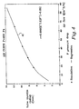
- Fig. 4 is the first curve, which describes the dependence of the valve's throttle radius on the air capacity (i.e., the air curve given of Fig. 4).
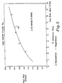
- the second curve indicates the gas slot dimension for a given gas flow (i.e., the gas curve of Fig. 5.
- the air curve is common for the whole range of capacities and pressure losses.
- the gas curve changes slightly from one given pressure drop to another, and may be determined for each particular pressure drop characteristic, or, alternatively, for at several selected neighboring pressure drops (e.g., values 350, 450 and 550 Pascals) of which other characteristics are determined from interpolated values between them.
- the software program FLUENT or another similar program, is inputted with information concerning the geometry of the valve, as well as desired air flow (discharge) [m 3 /h], gas flow (discharge), [m 3 /h] pressure drop along the valve [pa], valve throttle radius [mm], and gas slot width [mm].
- a curve 41 has been generated over a range of air flow in m 3 /h of from about 10 to 66 m 3 /h and extrapolated to the ends of curve 41 as shown.
- the air flow is plotted against the needed valve throttle radius to achieve the required air flow.
- the data developed for Fig. 4 is for a prescribed pressure drop of 450 Pascals because that value too was considered to be ideal for the system in use.
- the gas curve shown in Fig. 5 changes with the given pressure drop and is to be determined (from the software) for each particular case separately, or alternatively, for at least two selected neighboring pressure drops. Values of 350 and 550 Pascals were used in the considered case and curve 43 was obtained by interpolating between those two values to obtain a curve at 450 Pascals. One now selects the desired gas flow to obtain the required gas slot size that will produce optimum operation.
- the advantage of the present invention is that it eliminates the prior trial and error method. For each trial, both inlet and outlet plastic parts, mounted in an aluminum body, had to be completely manufactured. This requirement made the design process itself very slow and expensive. More critical is that the efficiency of the developed shape was not always satisfactory. Now, using the present invention, it is possible to achieve optimal computer provided efficiency and incorporates the integration of the inlet part with the aluminum body that does not change over a whole intended production range of various valve capacities and pressure drops.
Landscapes
- Engineering & Computer Science (AREA)
- Chemical & Material Sciences (AREA)
- Combustion & Propulsion (AREA)
- Mechanical Engineering (AREA)
- General Engineering & Computer Science (AREA)
- Multiple-Way Valves (AREA)
- Regulation And Control Of Combustion (AREA)
- Lift Valve (AREA)
- Valve Housings (AREA)
- Gas Burners (AREA)
Applications Claiming Priority (3)
| Application Number | Priority Date | Filing Date | Title |
|---|---|---|---|
| US08/987,335 US5971026A (en) | 1997-12-09 | 1997-12-09 | Internal geometry shape design for venturi tube-like gas-air mixing valve |
| US987335 | 1997-12-09 | ||
| PCT/US1998/025057 WO1999030081A1 (en) | 1997-12-09 | 1998-11-23 | Internal geometry shape design for venturi tube-like gas-air mixing valve |
Publications (2)
| Publication Number | Publication Date |
|---|---|
| EP1055085A1 EP1055085A1 (en) | 2000-11-29 |
| EP1055085B1 true EP1055085B1 (en) | 2002-01-16 |
Family
ID=25533192
Family Applications (1)
| Application Number | Title | Priority Date | Filing Date |
|---|---|---|---|
| EP98960420A Expired - Lifetime EP1055085B1 (en) | 1997-12-09 | 1998-11-23 | Internal geometry shape design for venturi tube-like gas-air mixing valve |
Country Status (7)
| Country | Link |
|---|---|
| US (1) | US5971026A (cs) |
| EP (1) | EP1055085B1 (cs) |
| JP (1) | JP2001526372A (cs) |
| CA (1) | CA2305145C (cs) |
| CZ (1) | CZ20002148A3 (cs) |
| DE (1) | DE69803229T2 (cs) |
| WO (1) | WO1999030081A1 (cs) |
Cited By (2)
| Publication number | Priority date | Publication date | Assignee | Title |
|---|---|---|---|---|
| US8512035B2 (en) | 2010-03-09 | 2013-08-20 | Honeywell Technologies Sarl | Mixing device for a gas burner |
| US8668491B2 (en) | 2009-10-06 | 2014-03-11 | Honeywell Technologies Sarl | Regulating device for gas burners |
Families Citing this family (18)
| Publication number | Priority date | Publication date | Assignee | Title |
|---|---|---|---|---|
| US6963155B1 (en) | 1997-04-24 | 2005-11-08 | Mitsubishi Denki Kabushiki Kaisha | Film acoustic wave device, manufacturing method and circuit device |
| US6741899B1 (en) | 2000-02-07 | 2004-05-25 | Visteon Global Tech., Inc. | System and method for designing a component |
| US8246344B1 (en) * | 2003-07-29 | 2012-08-21 | Samuel Schrock | Gas lamp |
| JP4032031B2 (ja) * | 2004-02-23 | 2008-01-16 | 本田技研工業株式会社 | 燃料ガス製造装置 |
| DE102004016361B4 (de) | 2004-04-01 | 2006-07-06 | Cybio Ag | Optisches Analysenmessgerät für Fluoreszenzmessungen an Multiprobenträgern |
| US8342148B2 (en) * | 2006-01-20 | 2013-01-01 | Ford Global Technologies | Throttle valve for internal combustion engine |
| US7472885B2 (en) * | 2006-03-06 | 2009-01-06 | Honeywell International, Inc. | Compact, lightweight cabin pressure control system butterfly outflow valve with redundancy features |
| US7963265B2 (en) * | 2008-12-05 | 2011-06-21 | Moto Tassinari, Inc. | Tunable air intake system |
| KR101179750B1 (ko) * | 2010-12-15 | 2012-09-04 | 주식회사 경동나비엔 | 출력조절장치를 구비한 가스보일러 및 가스보일러의 출력조절방법 |
| DE102011014117A1 (de) * | 2011-03-15 | 2012-09-20 | Ebm-Papst Landshut Gmbh | Mischvorrichtung zur Mischung von Verbrennungsluft und Gas für ein Gasgerät |
| KR101259764B1 (ko) | 2012-02-15 | 2013-05-07 | 주식회사 경동나비엔 | 연소기기용 듀얼 벤츄리 |
| CN104275102A (zh) | 2013-07-02 | 2015-01-14 | 德昌电机(深圳)有限公司 | 文丘里混合器 |
| JP6488550B2 (ja) * | 2014-03-27 | 2019-03-27 | 三浦工業株式会社 | ボイラ |
| US9746176B2 (en) * | 2014-06-04 | 2017-08-29 | Lochinvar, Llc | Modulating burner with venturi damper |
| WO2017033747A1 (ja) * | 2015-08-24 | 2017-03-02 | 株式会社村田製作所 | 気体混合器、気体混合装置 |
| JP6634909B2 (ja) * | 2016-03-18 | 2020-01-22 | 三浦工業株式会社 | ベンチュリノズル及び該ベンチュリノズルを備える燃料供給装置 |
| CN106500100A (zh) * | 2016-12-29 | 2017-03-15 | 宁波方太厨具有限公司 | 一种引射管结构 |
| KR101956541B1 (ko) * | 2017-08-29 | 2019-06-24 | 린나이코리아 주식회사 | 가스보일러용 벤츄리장치 |
Family Cites Families (19)
| Publication number | Priority date | Publication date | Assignee | Title |
|---|---|---|---|---|
| US1195915A (en) * | 1916-08-22 | Steam-jet | ||
| US2361150A (en) * | 1941-01-24 | 1944-10-24 | Mathieson Alkali Works Inc | Method and apparatus for admitting chlorine to a liquid stream |
| US2424654A (en) * | 1944-06-03 | 1947-07-29 | Lindberg Eng Co | Fluid mixing device |
| US2953160A (en) * | 1958-08-20 | 1960-09-20 | Akron Brass Mfg Co Inc | Bypass proportioner |
| DE1904014C3 (de) * | 1969-01-28 | 1974-06-20 | Noll Maschinenfabrik Gmbh, 4950 Minden | Vorrichtung zum kontinuierlichen Vereinigen von Getränkekomponenten in einstellbarem Mengenverhältnis |
| US3684189A (en) * | 1971-05-12 | 1972-08-15 | Zink Co John | Pressurized fuel burner |
| US4009988A (en) * | 1975-12-29 | 1977-03-01 | Lincoln Brass Works, Inc. | Gas valve and mixing tube assembly for gas burner |
| US5002481A (en) * | 1986-08-08 | 1991-03-26 | Forschungszentrum Julich Gmbh | Apparatus for generating a combustible gaseous mixture |
| US4845952A (en) * | 1987-10-23 | 1989-07-11 | General Electric Company | Multiple venturi tube gas fuel injector for catalytic combustor |
| US4966001A (en) * | 1987-10-23 | 1990-10-30 | General Electric Company | Multiple venturi tube gas fuel injector for catalytic combustor |
| AT395763B (de) * | 1989-04-13 | 1993-03-25 | Vaillant Gmbh | Atmosphaerischer brenner |
| US5140820A (en) * | 1990-11-14 | 1992-08-25 | Edward Booz | Carburetion and combustion system for gas turbine engines |
| US5257499A (en) * | 1991-09-23 | 1993-11-02 | General Electric Company | Air staged premixed dry low NOx combustor with venturi modulated flow split |
| US5307634A (en) * | 1992-02-26 | 1994-05-03 | United Technologies Corporation | Premix gas nozzle |
| US5377483A (en) * | 1993-07-07 | 1995-01-03 | Mowill; R. Jan | Process for single stage premixed constant fuel/air ratio combustion |
| US5572862A (en) * | 1993-07-07 | 1996-11-12 | Mowill Rolf Jan | Convectively cooled, single stage, fully premixed fuel/air combustor for gas turbine engine modules |
| US5450724A (en) * | 1993-08-27 | 1995-09-19 | Northern Research & Engineering Corporation | Gas turbine apparatus including fuel and air mixer |
| US5611684A (en) * | 1995-04-10 | 1997-03-18 | Eclipse, Inc. | Fuel-air mixing unit |
| JPH10227418A (ja) * | 1997-02-17 | 1998-08-25 | Harman Co Ltd | コンロ用ガスバーナ |
-
1997
- 1997-12-09 US US08/987,335 patent/US5971026A/en not_active Expired - Fee Related
-
1998
- 1998-11-23 EP EP98960420A patent/EP1055085B1/en not_active Expired - Lifetime
- 1998-11-23 CA CA 2305145 patent/CA2305145C/en not_active Expired - Fee Related
- 1998-11-23 JP JP2000524611A patent/JP2001526372A/ja active Pending
- 1998-11-23 WO PCT/US1998/025057 patent/WO1999030081A1/en not_active Ceased
- 1998-11-23 DE DE69803229T patent/DE69803229T2/de not_active Expired - Fee Related
- 1998-11-23 CZ CZ20002148A patent/CZ20002148A3/cs unknown
Cited By (2)
| Publication number | Priority date | Publication date | Assignee | Title |
|---|---|---|---|---|
| US8668491B2 (en) | 2009-10-06 | 2014-03-11 | Honeywell Technologies Sarl | Regulating device for gas burners |
| US8512035B2 (en) | 2010-03-09 | 2013-08-20 | Honeywell Technologies Sarl | Mixing device for a gas burner |
Also Published As
| Publication number | Publication date |
|---|---|
| DE69803229T2 (de) | 2002-08-22 |
| CA2305145C (en) | 2007-04-24 |
| CA2305145A1 (en) | 1999-06-17 |
| US5971026A (en) | 1999-10-26 |
| DE69803229D1 (de) | 2002-02-21 |
| WO1999030081A1 (en) | 1999-06-17 |
| CZ20002148A3 (cs) | 2001-11-14 |
| JP2001526372A (ja) | 2001-12-18 |
| EP1055085A1 (en) | 2000-11-29 |
Similar Documents
| Publication | Publication Date | Title |
|---|---|---|
| EP1055085B1 (en) | Internal geometry shape design for venturi tube-like gas-air mixing valve | |
| CN1050893C (zh) | 用于减少燃气轮机燃烧室中燃料对空气浓度的装置和方法 | |
| EP0763692A2 (en) | Oxy-fuel burner having coaxial fuel and oxidant outlets | |
| EP0616170B1 (en) | Apparatus and method for mixing gaseous fuel and air for combustion | |
| US7654090B2 (en) | Burner and method for operating a gas turbine | |
| US5165606A (en) | Method for operating a pressure atomization nozzle | |
| US4482313A (en) | Gasburner system | |
| CA1191778A (en) | High efficiency gas burner | |
| GB2287312A (en) | Gas turbine combustion system | |
| JPH0849802A (ja) | 水管群を有するボイラの燃焼装置と該燃焼装置を使用するボイラの燃焼方法 | |
| EP0128541A1 (en) | Gas turbine combustor | |
| US6050809A (en) | Immersion tube burner with improved flame stability | |
| JPH0531050B2 (cs) | ||
| JP4347643B2 (ja) | 予混合バーナとガスタービン及び燃料を燃焼させる方法 | |
| KR20060047385A (ko) | 노즐 | |
| US5983641A (en) | Tail pipe of gas turbine combustor and gas turbine combustor having the same tail pipe | |
| EP2501994B1 (en) | Flow control device | |
| EP4251922B1 (en) | Reduced-emission industrial burner and apparatus | |
| US6551098B2 (en) | Variable firing rate fuel burner | |
| US5688469A (en) | Gas mixer for cutting torches | |
| KR101335227B1 (ko) | 로(爐) 상단연소식 열풍로 | |
| US6006523A (en) | Gas turbine combustor with angled tube section | |
| US20210199285A1 (en) | Integrated Gas Orifice | |
| US5507438A (en) | Fuel gas and oxygen mixer for cutting torches | |
| RU2193142C1 (ru) | Газовая горелка для печи подогрева нефти |
Legal Events
| Date | Code | Title | Description |
|---|---|---|---|
| PUAI | Public reference made under article 153(3) epc to a published international application that has entered the european phase |
Free format text: ORIGINAL CODE: 0009012 |
|
| 17P | Request for examination filed |
Effective date: 20000331 |
|
| AK | Designated contracting states |
Kind code of ref document: A1 Designated state(s): DE FR GB |
|
| GRAG | Despatch of communication of intention to grant |
Free format text: ORIGINAL CODE: EPIDOS AGRA |
|
| 17Q | First examination report despatched |
Effective date: 20010406 |
|
| GRAG | Despatch of communication of intention to grant |
Free format text: ORIGINAL CODE: EPIDOS AGRA |
|
| GRAH | Despatch of communication of intention to grant a patent |
Free format text: ORIGINAL CODE: EPIDOS IGRA |
|
| GRAH | Despatch of communication of intention to grant a patent |
Free format text: ORIGINAL CODE: EPIDOS IGRA |
|
| GRAA | (expected) grant |
Free format text: ORIGINAL CODE: 0009210 |
|
| REG | Reference to a national code |
Ref country code: GB Ref legal event code: IF02 |
|
| AK | Designated contracting states |
Kind code of ref document: B1 Designated state(s): DE FR GB |
|
| REF | Corresponds to: |
Ref document number: 69803229 Country of ref document: DE Date of ref document: 20020221 |
|
| PLBE | No opposition filed within time limit |
Free format text: ORIGINAL CODE: 0009261 |
|
| STAA | Information on the status of an ep patent application or granted ep patent |
Free format text: STATUS: NO OPPOSITION FILED WITHIN TIME LIMIT |
|
| 26N | No opposition filed | ||
| PGFP | Annual fee paid to national office [announced via postgrant information from national office to epo] |
Ref country code: DE Payment date: 20071130 Year of fee payment: 10 |
|
| PGFP | Annual fee paid to national office [announced via postgrant information from national office to epo] |
Ref country code: FR Payment date: 20071105 Year of fee payment: 10 |
|
| PGFP | Annual fee paid to national office [announced via postgrant information from national office to epo] |
Ref country code: GB Payment date: 20081008 Year of fee payment: 11 |
|
| REG | Reference to a national code |
Ref country code: FR Ref legal event code: ST Effective date: 20090731 |
|
| PG25 | Lapsed in a contracting state [announced via postgrant information from national office to epo] |
Ref country code: DE Free format text: LAPSE BECAUSE OF NON-PAYMENT OF DUE FEES Effective date: 20090603 |
|
| GBPC | Gb: european patent ceased through non-payment of renewal fee |
Effective date: 20091123 |
|
| PG25 | Lapsed in a contracting state [announced via postgrant information from national office to epo] |
Ref country code: GB Free format text: LAPSE BECAUSE OF NON-PAYMENT OF DUE FEES Effective date: 20091123 |
|
| PG25 | Lapsed in a contracting state [announced via postgrant information from national office to epo] |
Ref country code: FR Free format text: LAPSE BECAUSE OF NON-PAYMENT OF DUE FEES Effective date: 20081130 |
|
| P01 | Opt-out of the competence of the unified patent court (upc) registered |
Effective date: 20230525 |