EP1054702B1 - Verbesserungen an medizinischen injektionsvorrichtungen - Google Patents
Verbesserungen an medizinischen injektionsvorrichtungen Download PDFInfo
- Publication number
- EP1054702B1 EP1054702B1 EP99905058A EP99905058A EP1054702B1 EP 1054702 B1 EP1054702 B1 EP 1054702B1 EP 99905058 A EP99905058 A EP 99905058A EP 99905058 A EP99905058 A EP 99905058A EP 1054702 B1 EP1054702 B1 EP 1054702B1
- Authority
- EP
- European Patent Office
- Prior art keywords
- injector
- spring
- sleeve
- trigger
- housing
- Prior art date
- Legal status (The legal status is an assumption and is not a legal conclusion. Google has not performed a legal analysis and makes no representation as to the accuracy of the status listed.)
- Expired - Lifetime
Links
Images

Classifications
-
- A—HUMAN NECESSITIES
- A61—MEDICAL OR VETERINARY SCIENCE; HYGIENE
- A61M—DEVICES FOR INTRODUCING MEDIA INTO, OR ONTO, THE BODY; DEVICES FOR TRANSDUCING BODY MEDIA OR FOR TAKING MEDIA FROM THE BODY; DEVICES FOR PRODUCING OR ENDING SLEEP OR STUPOR
- A61M5/00—Devices for bringing media into the body in a subcutaneous, intra-vascular or intramuscular way; Accessories therefor, e.g. filling or cleaning devices, arm-rests
- A61M5/178—Syringes
- A61M5/20—Automatic syringes, e.g. with automatically actuated piston rod, with automatic needle injection, filling automatically
- A61M5/2033—Spring-loaded one-shot injectors with or without automatic needle insertion
-
- A—HUMAN NECESSITIES
- A61—MEDICAL OR VETERINARY SCIENCE; HYGIENE
- A61M—DEVICES FOR INTRODUCING MEDIA INTO, OR ONTO, THE BODY; DEVICES FOR TRANSDUCING BODY MEDIA OR FOR TAKING MEDIA FROM THE BODY; DEVICES FOR PRODUCING OR ENDING SLEEP OR STUPOR
- A61M5/00—Devices for bringing media into the body in a subcutaneous, intra-vascular or intramuscular way; Accessories therefor, e.g. filling or cleaning devices, arm-rests
- A61M5/178—Syringes
- A61M5/31—Details
- A61M5/315—Pistons; Piston-rods; Guiding, blocking or restricting the movement of the rod or piston; Appliances on the rod for facilitating dosing ; Dosing mechanisms
- A61M5/31533—Dosing mechanisms, i.e. setting a dose
- A61M5/31545—Setting modes for dosing
- A61M5/31548—Mechanically operated dose setting member
- A61M5/3155—Mechanically operated dose setting member by rotational movement of dose setting member, e.g. during setting or filling of a syringe
Definitions
- This invention relates to medical injection devices. It is particularly concerned with the automatic firing of an injector having a barrel-like body with a sliding trigger on one side to eject the dose from a needle at its forward end.
- the action of the trigger is forwards against a stiff spring.
- a dose setting mechanism such as a rotary knob at its rear end which may be "clicked” round to a desired setting. All the trigger does is to release a spring which shoots a plunger forwards by an amount determined by the knob, this plunger co-operating with a piston in a capsule carrying the dose.
- Such injectors are well known (for example, as illustrated and described in WO-A-88 08725), but they require the user to insert the needle into the flesh first, before releasing the trigger. For self-users, this can be particularly difficult: it is natural to flinch and not push the needle in far enough.
- the aim of this invention is to provide a device that can automate this operation, ensuring that the injector needle is thrust in to the correct degree before the dose is ejected.
- an injection device comprising a firing device in combination with an injector of the type having firstly a barrel-like body enclosing a spring-loaded plunger to act on a piston within a capsule carrying a dose, and secondly a sliding trigger on one side of the body actuable to release the plunger spring to drive the plunger to cause ejection of the dose from a needle at the forward end of the body, the action of the trigger being forwards against a resistance
- the firing device comprising a generally cylindrical housing for surrounding the injector, a forward portion of the housing, open at its forward end to allow for projection of the injector needle, containing a locator spring capable of exerting a light rearward force on the injector to cause the needle to be located within said housing, and a rearward portion of the housing having an axially movable, forward spring-loaded actuating member to co-operate with the injector trigger, an external cocking mechanism operable to energise the spring loading of said actuating member
- an axial slot open from the forward end of the tubular member, receives the trigger and thereby locates the injector rotationally.
- the trigger will be engaged by the closed rear end of this slot.
- This arrangement also ensures that there is no mutual rotation between the tubular member, the housing and the sleeve.
- the sleeve carries the operating element which can only register in a position to release the snap engagement when the sleeve is moved forwards again after the device has been cocked.
- the operating element is preferably a button which engages in a slot in the housing and which has two different positions between which it can be shifted circumferentially of the sleeve only when that is forwards.
- one said position it acts by co-operation with a step in the slot as a preventer against the sleeve being slid rearwardly, that position also being the one, when the sleeve is moved forwards after cocking, in which the device can be fired.
- the other said position it allows the external sleeve to be slid rearwardly (and forwardly again), but is ineffective, when pressed, to fire the device.
- the sleeve When the device is for an injector having a rear end rotary adjusting knob to set the amount of dose to be ejected, the sleeve, in its forward position with the device cocked, conveniently leaves this knob exposed whereby, before firing, the user can rotate the knob to the required dosage. Marks on the knob may register with a mark on the end of the sleeve to assist gauging the amount of dosage set.
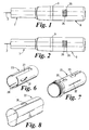
- the injector 1 to be fired is of known type and will not be described in detail. But its salient features for the purposes of this specification are a needle 2 at its forward end, a rotatable knob 3 at its rear end which is "clicked” round to set the desired dosage, and an elongate trigger 4 on the side of the barrel-like body towards the rear end whose firing action is forwards against a stiff spring or some other resistance.
- the body of the injector narrows at a sloping shoulder 5 towards a forward end portion which has opposed windows 6 through which the capsule containing the medium to be injected can be seen.
- the firing mechanism into which this injector fits has two assemblies 7 and 8 which screw together at 9.
- the nose assembly 7 consists of a stepped tube 10 with a cylindrical portion 11 forward of a shoulder 12 provided with opposed windows 13 which will register with the windows 6.
- This has an outwardly projecting rib 16 at its rear end, and a spring 17 acts between that rib and the root of the rib 14 to urge the locator ring 15 rearwardly with a fairly light force.
- Two diametrically opposed arms 18 project forwardly from the ring 15 and hooks 19 at their ends can snap past the rib 14 on assembly. The travel of the locator ring is determined by the length of these arms 18 to the hooks 19.
- the locator ring 15 has guide means (not shown) to keep it from rotating while allowing axial movement, and the gaps between the arms 18 register with the windows 13.
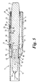
- the rear assembly 8 consists of a barrel 20, with a wide external annular rib 21 just to the rear of the screw thread joint 9, a sleeve 22 encasing the barrel 20 to the rear of the rib 21, a generally tubular locator 23 for the injector within the barrel urged forwardly by a powerful spring 24 reacting against an inturned flange 25 at the rear end of the barrel, and a trigger 26 captive to the sleeve 22.
- the locator 23 ( Figure 6) has a wide slot 27 extending lengthways, open at its forward end and with a blind rear end, to accommodate the injector trigger 4. Diametrically opposite this a tongue 28 is integrally formed with the tube at its forward end, the free end of the tongue being thickened to project proud of the otherwise cylindrical envelope.
- the barrel 20 ( Figure 7) has a slot 29 and an aperture 30 with which this tongue 28 can engage.
- the slot 29 is L-shaped in profile, open to the rear end of the barrel and with its short leg forward and aligned axially with the aperture 30.
- the locator 23 also has two diametrically opposed fins 31 which project through longitudinal slots 32 in the barrel 20, the leading edges of these fins being radial but the rear edges having a shallow slope so that the tube is radially contracted by a wedging action as it is forced rearwardly into the barrel on assembly.
- the slot 27 makes this deformation possible.
- the fins 31 reach the slots 32 they spring outwards making the locator 23 captive to the barrel 20.
- their tips are then proud of the barrel and the sleeve 22 ( Figure 8) has longitudinal slots 33 in which those tips can engage in like manner, making the sleeve captive also.
- the leading ends of the slots 33 serve as stops in a manner described below.
- the fins 31 also ensure that there is no mutual rotation between the locator 23, the barrel 20 and the sleeve 22.
- a single fin might suffice, but two are preferred.
- the trigger 26 has an exposed button 34 projecting through the slot 29, in which it is captive, and through an aperture 35 in the sleeve 22. This aperture allows the button to be shifted circumferentially between the positions shown in Figures 1 and 2 when it registers with the wide, forward end of the slot 29.
- the trigger is retained by a plate-like extension 36 from its base which engages under the periphery of the aperture 35 and which at its rear end has an inwardly projecting wedge-shaped stud 37. Below the front of the button there is a thickened portion 38 to co-operate with the tongue 28.
- the rear ends of the barrel 20, the sleeve 22 and the locator 23 are open so that the injector 1 can be fitted as shown in Figure 3, the rear end of its trigger 4 bearing against the closed end of the slot 27 and its dose adjusting knob 3 just exposed at the rear end of the injector.
- the sleeve 22 will have a mark against which rotation of the knob 3 can be gauged; the mark on the injector itself being hidden inside the assembly 8.
- the nose assembly 7 is screwed on, the locator ring 15 engaging the sloping shoulder 5 of the injector and being forced forwardly in relation to the tube 10 against the spring 17.
- the forward end of the ring 15 bears against the rib 14 with the spring 17 compressed. But that spring is not nearly powerful enough to overcome the spring 24 and the locator 23 remains in the forward position with the tongue 28 in the aperture 30.
- the needle 2 is left exposed projecting forward of the nose assembly 7. In practice, it will have a protective sheath while this fitting together is carried out, and it will not be removed until just before use.
- the stud 37 is captive in the slot 29, preventing the sleeve 22 from moving rearwardly.
- the device is in an idle or non-ready condition.
- the trigger 26 is pushed circumferentially to the Figure 2 position to take the stud 37 out of engagement with the step formed by the short leg of the L-shaped slot 29.
- This trigger movement also takes the thickened portion 38 out of axial alignment with the tongue 28.
- the sleeve 22 can then be pulled back and, acting through the forward ends of its slots 33 and the fins 31, this also retracts the locator 23, compressing the spring 24.
- the tongue 28 snaps into the slot 29, latching the device in the position of Figure 4.
- the injector 1 is pushed back by the spring 17 acting through the locator ring 15 and the needle 2 is withdrawn into the tube 10.
- the sleeve 22 is now slid forwards again to abut the rib 21, fully exposing the knob 3, which is rotated to set the required dose.
- the trigger 26 is pushed back circumferentially to the Figure 1 position so that the stud 37 re-enters the short leg of the slot 29 while the portion 38 comes directly over the free end of the tongue 28. In this position of Figure 5 the device is ready to fire.
- the free end of nose portion 11 is held against the area of skin where the injection is to be made and the button 34 pressed. This releases the tongue 28 from the slot 29 and the spring 24 shoots the locator 23 forwards.
- the closed end of the slot 27 bearing on the trigger 4 carries the injector forwards as well, causing the needle 2 to penetrate the skin.
- the trigger 4 is not immediately activated, being held rearwardly by a spring or other resistance stiffer than the spring 17. But when the locator ring 15 meets the rib 12, the trigger 4 will be pressed forward sufficiently to trip the action of the injector. The dose is therefore ejected as the forward travel of the injector is completed, back to the Figure 3 condition.
- the knob 3 returns to its zero position during this ejection.
- the cycle is then ready to be repeated.
Claims (6)
- Injektionsvorrichtung mit einer Schießvorrichtung in Verbindung mit einem Injektor (1), der erstens einen laufähnlichen Körper aufweist, welcher einen federbelasteten Stempel umschließt, um auf einen Kolben innerhalb einer mit einer Dosis versehenen Kapsel einzuwirken, und der zweitens einen gleitenden Auslöser (4) auf der einen Seite des Körpers aufweist, mit dem die Stempelfeder entspannbar ist, um den Stempel so anzutreiben, daß die Dosis aus einer Nadel am vorderen Ende des Körpers ausgestoßen wird, wobei die Wirkung des Auslösers in Richtung nach vorne gegen einen Widerstand erfolgt und die Schießvorrichtung ein im allgemeinen zylindrisches Gehäuse (20) aufweist, das den Injektor umgibt, wobei ferner ein vorderer Teil (11) des Gehäuses, der an seinem vorderen Ende offen ist, so daß die Injektornadel hervorragen kann, eine Feststellfeder (17) enthält, die auf den Injektor (1) eine leicht rückwärts gerichtete Kraft ausüben kann, um die Nadel zu veranlassen, innerhalb des Gehäuses zu bleiben, und ein rückwärtiger Teil des Gehäuses einen axial beweglichen Antriebskörper (23) aufweist, der unter nach vorne gerichteter Federspannung steht, um mit dem Injektorauslöser (4) zusammenzuwirken, wobei ferner ein externer Spannmechanismus (22) vorgesehen ist, der die Federspannung des Antriebskörpers (23) mit Hilfe einer Federkraft mit Energie versorgt, die größer ist als die leicht rückwärts gerichtete Kraft, und ein Betätigungselement (26) in der Lage ist, die Spannung in der Weise zu lösen, daß der Antriebskörper, der durch den Injektorauslöser wirkt, zunächst den Injektor nach vorne gegen die leicht rückwärts gerichtete Kraft in eine Position schießt, in der eine Nadel herausragt, und danach den Widerstand im Injektor überwindet und den Injektorauslöser so betätigt, daß die Dosis aus dem Injektor ausgestoßen wird, und wobei der federbelastete Körper (23) im allgemeinen rohrförmig ausgebildet ist, um den Injektor zu schließen, und zwischen seinem hinteren Ende und einem inneren Anschlag (25) an dem hinteren Ende des Gehäuses (20) eine Schraubenfeder (24) wirkt, dadurch gekennzeichnet, daß der Spannmechanismus eine Hülse (22) ist, die sich über dem hinteren Teil des Gehäuses (20) befindet und wenigstens einen seitlichen Vorsprung (31) aufweist, der von dem federbelasteten rohrförmigen Körper (23) ausgehend sich durch einen axial-parallelen Schlitz (32) im Gehäuse (20) in einen axial-parallelen Schlitz (33) in der Hülse erstreckt, wobei die Spannwirkung darin besteht, daß die Hülse so nach hinten gezogen wird, daß der Vorsprung (31), der mit dem vorderen Ende seines Schlitzes (33) in Eingriff steht, den rohrförmigen Körper (23) mitnimmt, bis zwischen dem rohrförmigen Körper (23) und dem Gehäuse (20) ein Schnappeingriff stattfindet und wobei gleichzeitig der Injektor durch die Feststellfeder zurückgestoßen wird.
- Injektionsvorrichtung nach Anspruch 1, dadurch gekennzeichnet, daß ein axialer Schlitz (27), der sich von dem vorderen Ende des rohrförmigen Körpers (23) öffnet, den Auslöser (26) aufnimmt, und dadurch die Drehrichtung des Injektors festlegt.
- Injektionsvorrichtung nach Anspruch 1 oder 2, dadurch gekennzeichnet, daß die Hülse (20) das Betätigungselement (26) trägt, das nur in einer Position in Überdeckung stehen kann, in der der Schnappeingriff gelöst wird, sobald die Hülse wieder vorwärts bewegt wird, nachdem die Vorrichtung gespannt worden ist.
- Injektionsvorrichtung nach Anspruch 3, dadurch gekennzeichnet, daß das Betätigungselement ein Knopf (34) ist, der in einen Schlitz im Gehäuse (29) eingreift und zwei verschiedene Stellungen hat, zwischen denen er in Umfangsrichtung der Hülse nur dann verschoben werden kann, wenn er sich vorne befindet, wobei er in der Einstellung mit einer Stufe in dem Schlitz als Schutz dagegen zusammenwirkt, daß die Hülse nach hinten geschoben wird in eine Stellung, die derjenigen entspricht, die die Hülse einnimmt, wenn sie nach dem Spannen vorwärts bewegt wird, wobei die Vorrichtung abgeschossen werden kann, und wobei in der anderen Stellung der äußeren Hülse ermöglicht wird, nach hinten und wieder vorwärts zu gleiten, die Vorrichtung jedoch im eingedrückten Zustand des Knopfes nicht abgeschossen werden kann.
- Injektionsvorrichtung nach einem der vorhergehenden Ansprüche, dadurch gekennzeichnet, daß die Vorrichtung für einen Injektor geschaffen ist, dessen hinteres Ende einen Dreheinstellgriff (3) aufweist, mit dem die Menge der zu injizierenden Dosis einstellbar ist, wobei die Hülse (22) in ihrer vorderen Stellung bei gespannter Vorrichtung den Griff frei zugänglich läßt, wodurch der Benutzer den Griff vor dem Abschießen in die gewünschte Dosierstellung drehen kann.
- Injektionsvorrichtung nach Anspruch 5, dadurch gekennzeichnet, daß Markierungen auf dem Griff mit einer Markierung auf dem Ende der Hülse in Überdeckung stehen, um die Messung der Größe der Dosiereinstellung zu unterstützen.
Applications Claiming Priority (3)
| Application Number | Priority Date | Filing Date | Title |
|---|---|---|---|
| GBGB9803084.4A GB9803084D0 (en) | 1998-02-14 | 1998-02-14 | Improvements relating to medical injection devices |
| GB9803084 | 1998-02-14 | ||
| PCT/GB1999/000473 WO1999040958A1 (en) | 1998-02-14 | 1999-02-15 | Improvements relating to medical injection devices |
Publications (2)
| Publication Number | Publication Date |
|---|---|
| EP1054702A1 EP1054702A1 (de) | 2000-11-29 |
| EP1054702B1 true EP1054702B1 (de) | 2005-11-02 |
Family
ID=10826943
Family Applications (1)
| Application Number | Title | Priority Date | Filing Date |
|---|---|---|---|
| EP99905058A Expired - Lifetime EP1054702B1 (de) | 1998-02-14 | 1999-02-15 | Verbesserungen an medizinischen injektionsvorrichtungen |
Country Status (6)
| Country | Link |
|---|---|
| US (1) | US6932793B1 (de) |
| EP (1) | EP1054702B1 (de) |
| JP (1) | JP4152074B2 (de) |
| DE (1) | DE69928083T2 (de) |
| GB (1) | GB9803084D0 (de) |
| WO (1) | WO1999040958A1 (de) |
Families Citing this family (75)
| Publication number | Priority date | Publication date | Assignee | Title |
|---|---|---|---|---|
| GB9803084D0 (en) | 1998-02-14 | 1998-04-08 | Owen Mumford Ltd | Improvements relating to medical injection devices |
| DE29912965U1 (de) * | 1999-07-24 | 1999-09-16 | Hoelzle Dieter Tech Projekte | Injektionsvorrichtung |
| DE60323729D1 (de) | 2002-02-11 | 2008-11-06 | Antares Pharma Inc | Intradermales injektionsgerät |
| GB0312852D0 (en) * | 2003-06-05 | 2003-07-09 | Owen Mumford Ltd | Improvements relating to syringe firing mechanisms |
| DE10342059B4 (de) * | 2003-09-11 | 2007-03-01 | Tecpharma Licensing Ag | Verabreichungsvorrichtung mit Einstech- und Ausschütteinrichtung |
| DE10351599A1 (de) * | 2003-11-05 | 2005-06-16 | Tecpharma Licensing Ag | Autoinjektionsvorrichtung |
| GB2414404B (en) | 2004-05-28 | 2009-06-03 | Cilag Ag Int | Injection device |
| GB2414401B (en) | 2004-05-28 | 2009-06-17 | Cilag Ag Int | Injection device |
| GB2414405B (en) | 2004-05-28 | 2009-01-14 | Cilag Ag Int | Injection device |
| GB2414399B (en) | 2004-05-28 | 2008-12-31 | Cilag Ag Int | Injection device |
| GB2414775B (en) | 2004-05-28 | 2008-05-21 | Cilag Ag Int | Releasable coupling and injection device |
| GB2414403B (en) | 2004-05-28 | 2009-01-07 | Cilag Ag Int | Injection device |
| GB2414406B (en) | 2004-05-28 | 2009-03-18 | Cilag Ag Int | Injection device |
| GB2414402B (en) | 2004-05-28 | 2009-04-22 | Cilag Ag Int | Injection device |
| GB2414400B (en) | 2004-05-28 | 2009-01-14 | Cilag Ag Int | Injection device |
| GB2414409B (en) | 2004-05-28 | 2009-11-18 | Cilag Ag Int | Injection device |
| GB0414054D0 (en) | 2004-06-23 | 2004-07-28 | Owen Mumford Ltd | Improvements relating to automatic injection devices |
| JP5216328B2 (ja) | 2005-01-24 | 2013-06-19 | アンタレス ファーマ インコーポレイテッド | あらかじめ充填された針補助シリンジジェット式注射器 |
| GB2424835B (en) | 2005-04-06 | 2010-06-09 | Cilag Ag Int | Injection device (modified trigger) |
| GB2424836B (en) | 2005-04-06 | 2010-09-22 | Cilag Ag Int | Injection device (bayonet cap removal) |
| GB2424838B (en) | 2005-04-06 | 2011-02-23 | Cilag Ag Int | Injection device (adaptable drive) |
| GB2427826B (en) | 2005-04-06 | 2010-08-25 | Cilag Ag Int | Injection device comprising a locking mechanism associated with integrally formed biasing means |
| GB2425062B (en) | 2005-04-06 | 2010-07-21 | Cilag Ag Int | Injection device |
| PT1759729E (pt) | 2005-08-30 | 2010-03-04 | Cilag Gmbh Int | Conjunto de agulha para um sistema de seringa previamente cheia |
| US20110098656A1 (en) | 2005-09-27 | 2011-04-28 | Burnell Rosie L | Auto-injection device with needle protecting cap having outer and inner sleeves |
| US8251947B2 (en) | 2006-05-03 | 2012-08-28 | Antares Pharma, Inc. | Two-stage reconstituting injector |
| WO2007131025A1 (en) | 2006-05-03 | 2007-11-15 | Antares Pharma, Inc. | Injector with adjustable dosing |
| CN101454034B (zh) | 2006-05-29 | 2012-05-23 | 诺沃-诺迪斯克有限公司 | 用于注射装置的机构 |
| GB2438591B (en) | 2006-06-01 | 2011-07-13 | Cilag Gmbh Int | Injection device |
| GB2438590B (en) | 2006-06-01 | 2011-02-09 | Cilag Gmbh Int | Injection device |
| GB2438593B (en) | 2006-06-01 | 2011-03-30 | Cilag Gmbh Int | Injection device (cap removal feature) |
| NZ572765A (en) | 2006-06-30 | 2012-08-31 | Abbott Biotech Ltd | Automatic injection device with rod driving syringe longitudinally split with radially compressible pair of wings along its length |
| US9259174B2 (en) * | 2007-04-20 | 2016-02-16 | Stat Medical Devices, Inc. | Retractable fluid collection device |
| WO2009114542A1 (en) | 2008-03-10 | 2009-09-17 | Antares Pharma, Inc. | Injector safety device |
| US8052645B2 (en) | 2008-07-23 | 2011-11-08 | Avant Medical Corp. | System and method for an injection using a syringe needle |
| US8177749B2 (en) | 2008-05-20 | 2012-05-15 | Avant Medical Corp. | Cassette for a hidden injection needle |
| CA2724641C (en) | 2008-05-20 | 2020-03-24 | Avant Medical Corp. | Autoinjector system |
| GB2461086B (en) | 2008-06-19 | 2012-12-05 | Cilag Gmbh Int | Injection device |
| GB2461085B (en) | 2008-06-19 | 2012-08-29 | Cilag Gmbh Int | Injection device |
| GB2461089B (en) | 2008-06-19 | 2012-09-19 | Cilag Gmbh Int | Injection device |
| GB2461087B (en) | 2008-06-19 | 2012-09-26 | Cilag Gmbh Int | Injection device |
| GB2461084B (en) | 2008-06-19 | 2012-09-26 | Cilag Gmbh Int | Fluid transfer assembly |
| AU2009279719B2 (en) | 2008-08-05 | 2015-07-23 | Antares Pharma, Inc. | Multiple dosage injector |
| GB0900930D0 (en) * | 2009-01-20 | 2009-03-04 | Future Injection Technologies Ltd | Injection device |
| AU2010226442A1 (en) | 2009-03-20 | 2011-10-13 | Antares Pharma, Inc. | Hazardous agent injection system |
| US20100286558A1 (en) * | 2009-04-08 | 2010-11-11 | Stat Medical Devices, Inc. | Fluid collection/injection device having quick release/removable double-ended needle and safety system |
| JP5677411B2 (ja) | 2009-04-29 | 2015-02-25 | アッヴィ バイオテクノロジー リミテッド | 自動注入機器 |
| NZ600069A (en) | 2009-12-15 | 2015-02-27 | Abbvie Biotechnology Ltd | Improved firing button for automatic injection device |
| ES2727275T3 (es) | 2010-04-21 | 2019-10-15 | Abbvie Biotechnology Ltd | Dispositivo automático de inyección portátil para la liberación controlada de agentes terapéuticos |
| US9022988B1 (en) | 2010-05-07 | 2015-05-05 | Kavan J. Shaban | System and method for controlling a self-injector device |
| KR101853607B1 (ko) | 2011-01-24 | 2018-05-03 | 애브비 바이오테크놀로지 리미티드 | 주사기로부터 니들 실드의 제거 및 자동 주사 디바이스들 |
| US8992477B2 (en) | 2011-01-24 | 2015-03-31 | Elcam Agricultural Cooperative Association Ltd. | Injector |
| EP2667918B1 (de) | 2011-01-24 | 2017-03-01 | AbbVie Biotechnology Ltd | Automatische injektionsvorrichtungen mit übersrpitzten griffflächen |
| CA2833748C (en) | 2011-04-20 | 2019-07-16 | Amgen Inc. | Autoinjector apparatus |
| US10092230B2 (en) | 2011-04-29 | 2018-10-09 | Stat Medical Devices, Inc. | Fluid collection/injection device having safety needle assembly/cover and safety system and method |
| US9220660B2 (en) | 2011-07-15 | 2015-12-29 | Antares Pharma, Inc. | Liquid-transfer adapter beveled spike |
| US8496619B2 (en) | 2011-07-15 | 2013-07-30 | Antares Pharma, Inc. | Injection device with cammed ram assembly |
| EP2583705A1 (de) * | 2011-10-21 | 2013-04-24 | Sanofi-Aventis Deutschland GmbH | Anzeigeanordnung für einen automatischen Injektor |
| US9078978B2 (en) | 2011-12-28 | 2015-07-14 | Stat Medical Devices, Inc. | Needle assembly with safety system for a syringe or fluid sampling device and method of making and using the same |
| DK2822618T3 (da) | 2012-03-06 | 2024-01-22 | Antares Pharma Inc | Forfyldt nål med brudkraftfunktion |
| EP2833944A4 (de) | 2012-04-06 | 2016-05-25 | Antares Pharma Inc | Verabreichung von testosteron-zusammensetzungen durch nadelgestützte düseninjektion |
| USD808010S1 (en) | 2012-04-20 | 2018-01-16 | Amgen Inc. | Injection device |
| USD898908S1 (en) | 2012-04-20 | 2020-10-13 | Amgen Inc. | Pharmaceutical product cassette for an injection device |
| WO2013169800A1 (en) | 2012-05-07 | 2013-11-14 | Antares Pharma, Inc. | Injection device with cammed ram assembly |
| EP2953667B1 (de) | 2013-02-11 | 2019-10-23 | Antares Pharma, Inc. | Nadelgestützte düseninjektionsvorrichtung mit reduzierter auslöserkraft |
| US9707354B2 (en) | 2013-03-11 | 2017-07-18 | Antares Pharma, Inc. | Multiple dosage injector with rack and pinion dosage system |
| WO2014165136A1 (en) | 2013-03-12 | 2014-10-09 | Antares Pharma, Inc. | Constant volume prefilled syringes and kits thereof |
| TWI580451B (zh) | 2013-03-15 | 2017-05-01 | 安美基公司 | 用於注射器之匣盒及使用具有自動注射器及匣盒之自動注射器設備之方法 |
| EP3593839A1 (de) | 2013-03-15 | 2020-01-15 | Amgen Inc. | Arzneimittelkassette |
| GB2515039B (en) | 2013-06-11 | 2015-05-27 | Cilag Gmbh Int | Injection Device |
| GB2515038A (en) | 2013-06-11 | 2014-12-17 | Cilag Gmbh Int | Injection device |
| GB2517896B (en) | 2013-06-11 | 2015-07-08 | Cilag Gmbh Int | Injection device |
| GB2515032A (en) | 2013-06-11 | 2014-12-17 | Cilag Gmbh Int | Guide for an injection device |
| US10661014B2 (en) | 2015-01-21 | 2020-05-26 | Antares Pharma, Inc. | Injection device having variable dosing |
| CN110101941B (zh) * | 2019-05-29 | 2024-01-30 | 浙江伏尔特医疗器械股份有限公司 | 一种双向止血止液安全装置 |
Family Cites Families (9)
| Publication number | Priority date | Publication date | Assignee | Title |
|---|---|---|---|---|
| DE3715258C2 (de) | 1987-05-08 | 1996-10-31 | Haselmeier Wilhelm Fa | Injektionsgerät |
| GB9111600D0 (en) * | 1991-05-30 | 1991-07-24 | Owen Mumford Ltd | Improvements relating to injection devices |
| DE69427226T2 (de) | 1993-03-24 | 2001-08-30 | Owen Mumford Ltd | Vorrichtung zur injektion |
| FR2715071B1 (fr) * | 1994-01-17 | 1996-03-01 | Aguettant Lab | Injecteur automatique de médicament. |
| GB9412301D0 (en) * | 1994-06-17 | 1994-08-10 | Safe T Ltd | Hollow-needle drugs etc applicators |
| US5637094A (en) | 1994-11-04 | 1997-06-10 | Pos-T-Vac, Inc. | Multiple dosage syringe |
| FR2733155B1 (fr) * | 1995-04-18 | 1997-09-19 | Tebro | Auto-injecteur rechargeable |
| GB9803084D0 (en) | 1998-02-14 | 1998-04-08 | Owen Mumford Ltd | Improvements relating to medical injection devices |
| GB9808408D0 (en) * | 1998-04-18 | 1998-06-17 | Owen Mumford Ltd | Improvements relating to injection devices |
-
1998
- 1998-02-14 GB GBGB9803084.4A patent/GB9803084D0/en not_active Ceased
-
1999
- 1999-02-15 DE DE69928083T patent/DE69928083T2/de not_active Expired - Lifetime
- 1999-02-15 US US09/622,159 patent/US6932793B1/en not_active Expired - Fee Related
- 1999-02-15 EP EP99905058A patent/EP1054702B1/de not_active Expired - Lifetime
- 1999-02-15 WO PCT/GB1999/000473 patent/WO1999040958A1/en active IP Right Grant
- 1999-02-15 JP JP2000531209A patent/JP4152074B2/ja not_active Expired - Fee Related
Also Published As
| Publication number | Publication date |
|---|---|
| WO1999040958A1 (en) | 1999-08-19 |
| DE69928083D1 (de) | 2005-12-08 |
| JP4152074B2 (ja) | 2008-09-17 |
| JP2002502672A (ja) | 2002-01-29 |
| US6932793B1 (en) | 2005-08-23 |
| GB9803084D0 (en) | 1998-04-08 |
| EP1054702A1 (de) | 2000-11-29 |
| DE69928083T2 (de) | 2006-07-20 |
Similar Documents
| Publication | Publication Date | Title |
|---|---|---|
| EP1054702B1 (de) | Verbesserungen an medizinischen injektionsvorrichtungen | |
| EP0906131B1 (de) | Verbesserte injektionsvorrichtung | |
| US7695453B2 (en) | Injection devices | |
| US6159181A (en) | Injection device | |
| US9707344B2 (en) | Autoinjector | |
| EP1071488B1 (de) | Verbesserungen bezüglich injektionsvorrichtungen | |
| JP6018134B2 (ja) | 注射筒安全シールドおよび自動注射器 | |
| CN114191658B (zh) | 注入设备 | |
| EP0651662B1 (de) | Verbesserte injektionsvorrichtungen | |
| US20110196311A1 (en) | Injection devices | |
| WO1996007443A1 (en) | Improvements relating to injection devices | |
| US9802005B2 (en) | Medicament delivery device | |
| JP2004537376A (ja) | 注射装置に関する改良 | |
| US6638255B1 (en) | Injection device | |
| JPH02502360A (ja) | 火薬‐作動留め具打込み工具 | |
| US3968784A (en) | Spring type projectile projecting device | |
| US5202533A (en) | Drug injection apparatus for an animal | |
| TW201740988A (zh) | 用於藥物輸送裝置的施用機構 | |
| US4074843A (en) | Fastening element feeding device for an explosive powder driven setting gun | |
| CN116115863A (zh) | 注射装置 | |
| JPS6344717Y2 (de) |
Legal Events
| Date | Code | Title | Description |
|---|---|---|---|
| PUAI | Public reference made under article 153(3) epc to a published international application that has entered the european phase |
Free format text: ORIGINAL CODE: 0009012 |
|
| 17P | Request for examination filed |
Effective date: 20000904 |
|
| AK | Designated contracting states |
Kind code of ref document: A1 Designated state(s): DE FR GB |
|
| 17Q | First examination report despatched |
Effective date: 20031128 |
|
| GRAP | Despatch of communication of intention to grant a patent |
Free format text: ORIGINAL CODE: EPIDOSNIGR1 |
|
| GRAS | Grant fee paid |
Free format text: ORIGINAL CODE: EPIDOSNIGR3 |
|
| GRAA | (expected) grant |
Free format text: ORIGINAL CODE: 0009210 |
|
| AK | Designated contracting states |
Kind code of ref document: B1 Designated state(s): DE FR GB |
|
| REG | Reference to a national code |
Ref country code: GB Ref legal event code: FG4D |
|
| REF | Corresponds to: |
Ref document number: 69928083 Country of ref document: DE Date of ref document: 20051208 Kind code of ref document: P |
|
| ET | Fr: translation filed | ||
| PLBE | No opposition filed within time limit |
Free format text: ORIGINAL CODE: 0009261 |
|
| STAA | Information on the status of an ep patent application or granted ep patent |
Free format text: STATUS: NO OPPOSITION FILED WITHIN TIME LIMIT |
|
| 26N | No opposition filed |
Effective date: 20060803 |
|
| PGFP | Annual fee paid to national office [announced via postgrant information from national office to epo] |
Ref country code: FR Payment date: 20110309 Year of fee payment: 13 |
|
| REG | Reference to a national code |
Ref country code: FR Ref legal event code: ST Effective date: 20121031 |
|
| PG25 | Lapsed in a contracting state [announced via postgrant information from national office to epo] |
Ref country code: FR Free format text: LAPSE BECAUSE OF NON-PAYMENT OF DUE FEES Effective date: 20120229 |
|
| PGFP | Annual fee paid to national office [announced via postgrant information from national office to epo] |
Ref country code: DE Payment date: 20130327 Year of fee payment: 15 Ref country code: GB Payment date: 20130327 Year of fee payment: 15 |
|
| REG | Reference to a national code |
Ref country code: DE Ref legal event code: R119 Ref document number: 69928083 Country of ref document: DE |
|
| GBPC | Gb: european patent ceased through non-payment of renewal fee |
Effective date: 20140215 |
|
| REG | Reference to a national code |
Ref country code: DE Ref legal event code: R119 Ref document number: 69928083 Country of ref document: DE Effective date: 20140902 |
|
| PG25 | Lapsed in a contracting state [announced via postgrant information from national office to epo] |
Ref country code: GB Free format text: LAPSE BECAUSE OF NON-PAYMENT OF DUE FEES Effective date: 20140215 Ref country code: DE Free format text: LAPSE BECAUSE OF NON-PAYMENT OF DUE FEES Effective date: 20140902 |