EP1054573B1 - Device for mechanical coupling of a electromechanical hearing aid transducer implantable in a cavity in the mastoid - Google Patents
Device for mechanical coupling of a electromechanical hearing aid transducer implantable in a cavity in the mastoid Download PDFInfo
- Publication number
- EP1054573B1 EP1054573B1 EP00105203A EP00105203A EP1054573B1 EP 1054573 B1 EP1054573 B1 EP 1054573B1 EP 00105203 A EP00105203 A EP 00105203A EP 00105203 A EP00105203 A EP 00105203A EP 1054573 B1 EP1054573 B1 EP 1054573B1
- Authority
- EP
- European Patent Office
- Prior art keywords
- coupling
- transducer
- site
- flexible intermediate
- arrangement
- Prior art date
- Legal status (The legal status is an assumption and is not a legal conclusion. Google has not performed a legal analysis and makes no representation as to the accuracy of the status listed.)
- Expired - Lifetime
Links
Images
Classifications
-
- H—ELECTRICITY
- H04—ELECTRIC COMMUNICATION TECHNIQUE
- H04R—LOUDSPEAKERS, MICROPHONES, GRAMOPHONE PICK-UPS OR LIKE ACOUSTIC ELECTROMECHANICAL TRANSDUCERS; DEAF-AID SETS; PUBLIC ADDRESS SYSTEMS
- H04R25/00—Deaf-aid sets, i.e. electro-acoustic or electro-mechanical hearing aids; Electric tinnitus maskers providing an auditory perception
- H04R25/60—Mounting or interconnection of hearing aid parts, e.g. inside tips, housings or to ossicles
- H04R25/604—Mounting or interconnection of hearing aid parts, e.g. inside tips, housings or to ossicles of acoustic or vibrational transducers
- H04R25/606—Mounting or interconnection of hearing aid parts, e.g. inside tips, housings or to ossicles of acoustic or vibrational transducers acting directly on the eardrum, the ossicles or the skull, e.g. mastoid, tooth, maxillary or mandibular bone, or mechanically stimulating the cochlea, e.g. at the oval window
-
- A—HUMAN NECESSITIES
- A61—MEDICAL OR VETERINARY SCIENCE; HYGIENE
- A61F—FILTERS IMPLANTABLE INTO BLOOD VESSELS; PROSTHESES; DEVICES PROVIDING PATENCY TO, OR PREVENTING COLLAPSING OF, TUBULAR STRUCTURES OF THE BODY, e.g. STENTS; ORTHOPAEDIC, NURSING OR CONTRACEPTIVE DEVICES; FOMENTATION; TREATMENT OR PROTECTION OF EYES OR EARS; BANDAGES, DRESSINGS OR ABSORBENT PADS; FIRST-AID KITS
- A61F2/00—Filters implantable into blood vessels; Prostheses, i.e. artificial substitutes or replacements for parts of the body; Appliances for connecting them with the body; Devices providing patency to, or preventing collapsing of, tubular structures of the body, e.g. stents
- A61F2/02—Prostheses implantable into the body
- A61F2/18—Internal ear or nose parts, e.g. ear-drums
- A61F2002/183—Ear parts
Definitions
- the invention relates to a device for mechanically coupling an output - side converter part, which can be stimulated to mechanical vibrations, to a preselected coupling point on the ossicular chain, the stapes foot plate or the round window or an artificial window in the cochlea, in the artificial limb in an artificial mastoid cavity Vestibulum or in the labyrinth (equilibrium organ) final membrane, with a biocompatible, mechanically passive coupling arrangement which is connected to the output side transducer part and which extends in the implanted state of the mastoid into the tympanic cavity and rests with a remote from the hearing aid transducer Ankoppelende at the Ankoppelstelle.
- Implantable hearing systems differ from conventional hearing aids: the sound signal is converted into an electrical signal with a transducer (microphone) and amplified in an electronic signal processing stage; However, this amplified electrical signal is not supplied to an electro-acoustic transducer (speaker), but an implanted electromechanical transducer whose output side mechanical vibrations directly, ie with direct mechanical contact, the middle or inner ear are fed or indirectly by a frictional connection via an air gap at Example of electromagnetic transducer systems.
- the semi-implantable, piezoelectric hearing system of the Japanese group of Suzuki and Yanigahara requires the lack of Mittelohrossikel and a free tympanic cavity for an implantation of the transducer in order to couple the piezoelectric element to the stapes can (Yanigahara et al .: Efficacy of the partially implantable middle ear implant in middle and inner ear disorders Adv. Audiol., Vol. 4, Karger Basel (1988), pp. 149-159; Suzuki et al .: Implantation of partially implantable middle ear implant and the indication. Adv. Audiol., Vol. 4, Karger Basel (1988), p. 160-166).
- the ball-type electromagnetic transducer (Floating Mass Transducer FMT", US Pat. No. 5,624,376, US Pat. No. 5,554,096) is fixed directly to the long projection of the anvil with the middle ear intact with titanium clips.
- the electromagnetic transducer of the partially implantable FREDRICKSON system (Fredrickson et al .: Ongoing investigations into an implantable electro-magnetic hearing aid for moderate to severe sensorineural hearing loss, Otolaryngologic Clinics of North America, Vol. 28/1 (1995), pp. 107-121 ) is mechanically coupled directly to the anvil body with also intact ossicular chain of the middle ear.
- the converter can be designed as a so-called “floating mass” converter, that is, the transducer element does not require “Reactio” via a fixed screw with the skull bone, but it oscillates due to inertia laws with its transducer housing and transmits them directly onto a middle ossicle (US-A-5,624,376, US-A-5 554 096, US-A-5 707 338, WO 98/06236).
- the converter housing with implantable positioning and fixation systems must be fastened to the skull (advantageous embodiment DE-A-196 18 964 corresponding to US Pat. No. 5,788,711).
- a disadvantage of the variants according to b) is that a depression in the Zielossikel, preferably by means of suitable laser, must be introduced in order to apply the coupling element can. On the one hand, this is technically complicated and expensive, and on the other hand it entails risks for the patient.
- FREDRICKSON Ongoing investigations into an implantable electromagnetic hearing aid for moderate to severe sensorineural hearing loss, Otolaryngologic Clinics of North America, Vol. 28/1 (1995), pp.
- the hearing system according to LEYSIEFFER and ZENNER (HNO 1998, Vol. 46, 853-863 and 844-852) is based on the coupling of the oscillating transducer part to the anvil body for permanent and mechanically safe vibration transmission assumed that the tip of the coupling rod, which in the laser-induced Deepening of Mittelohrossikels is introduced long-term osseointegration undergoes, that is, the coupling rod fuses firmly with the ossicle, thus ensuring a secure transmission of dynamic pressure and tensile forces. This long-term effect is currently not scientifically proven or secured.
- the present invention has for its object to provide a device for coupling a hearing aid transducer and the transmission of the output side transducer oscillations to the middle or inner ear, while maintaining the advantages of the variant b) easier and safer to apply, during implantation in the Inner ear necessary, risky work minimized and also facilitates a possibly later becoming decoupling easier and favors an optimal waveform of Stirrupfußplatte.
- the device according to the invention provides for a coupling of the output-side transducer part of an electromechanical hearing aid transducer implantable in a mastoid cavity to an ossicle (hammer, anvil, stirrup, preferably anvil), to the stapes footplate or to a membrane terminating the round window or an artificial window by surface adhesion ,
- surface adhesion is to be understood as meaning adhesion under the influence of the molecular attractive forces acting on a sufficiently strong approach to the contact surfaces or mutual mechanical blocking of the contact surfaces without the use of an adhesive or cement. Air bubbles that are trapped in surface depressions can also contribute to a corresponding surface adhesion. If the contact surfaces are exposed to forces that seek to separate the surfaces, such air bubbles create a suction effect, which makes the separation considerably more difficult (Bild dermaschine, April 1999, p. 10).
- a fundamental advantage of such an adhesion coupling is that the coupling site of, for example, the ossicle is not "forced” primarily in the direction of vibration of the driving transducer, such "constraining” may result in a non-optimal waveform of the stapes foot plate in the oval window.
- a preferred mode of vibration is a piston-shaped oscillation of the stirrup base plate perpendicular to its plane.
- the ossicle when using the surface adhesion coupling, sets its (frequency-dependent) direction of oscillation due to the dynamic properties of the intact middle ear itself.
- a passive ossicle prosthesis with a head, a shaft and a bendable intermediate piece is known (WO 90/11737).
- the intermediate piece makes it possible to adjust the angular orientation of the shaft with respect to the head.
- the shaft is supported on the stapes arch, stapes leg or stapes foot plate while the prosthetic head rests against the eardrum or hammer under such bias that the eardrum is slightly tensioned.
- the head and stem of the prosthesis are preferably made of hydroxyapatite or a mixture of hydroxyapatite particles and silicone or polyurethane. Human tissue adheres to such a material, which is intended to support the fixation of the prosthesis in the middle ear.
- the coupling arrangement expediently has a coupling rod which is fixedly connected to the output-side converter part and, in the implanted state, extends from the mastoid cavity into the tympanic cavity and a coupling element which is connectable or connected to the end of the coupling rod remote from the output-side transducer part and forms the coupling end of the coupling arrangement
- a coupling rod is a mechanically rigid coupling member of relatively low mass, which may be fixedly attached to the outside of a vibratable membrane of the electromechanical hearing aid transducer and which in the implantation by the natural or artificially slightly enlarged aditus ad antrum, by opening the chorda -facialis angle or by an artificial hole from the mastoid can be pushed into the middle ear to be connected there via the coupling element with the desired coupling point. It is thereby ensured that the vibratory stimulus of the transducer largely lossless, that is, hard-sounding, is introduced into the target os
- the coupling rod and the coupling element can be connected to each other via a flexible intermediate member, which may be a separate component or which may be formed by the coupling element itself.
- the coupling element for the purpose of forming the flexible intermediate member may simply be provided with a constriction.
- the flexible intermediate member can automatically adjust optimally in terms of its solid angle or be adjusted by the surgeon intraoperatively individually optimally plastic.
- the flexible intermediate member may advantageously be designed as a spring element and consist of a Metallegierrung with memory effect or so-called "superelasticity", in particular nitinol.
- the use of such a material has the advantage that the transmitted force remains approximately the same even with different travel ranges.
- the coupling rod and the coupling element can also be connected to one another via a ball joint in order to achieve the above-described optimum solid angle adjustment.
- the coupling arrangement is designed and / or positioned in the implanted state so that the Ankoppelende touches the Ankoppelstelle without static bias or only with slight bias.
- a moisture film is formed at least in the implanted state between the coupling end and the coupling.
- a natural moisture film can be used, which is due to the present in the middle ear space humidity of 100%.
- the Ankoppelende may advantageously be concave prior to coupling with respect to the Ankoppelstelle. This results in the application of Ankoppelendes to the Ankoppelstelle a cavity which is compressed by lightly pressing the Ankoppelendes. The trained negative pressure supports the liability.
- the coupling site can also be formed by an optionally anatomically adaptable coupling plate, which in the implanted state is firmly connected to the surface of the part of the ossicle chain to be contacted, the stapes footplate or a membrane closing off the round window or an artificial window, for example adhesively bonded or cemented on.
- an optionally anatomically adaptable coupling plate which in the implanted state is firmly connected to the surface of the part of the ossicle chain to be contacted, the stapes footplate or a membrane closing off the round window or an artificial window, for example adhesively bonded or cemented on.
- the coupling element has a large-area, openwork structure at the coupling end and / or is provided with a plurality of resilient arms.
- an electromechanical hearing aid transducer 13 is fixed by means of a positioning and fixing system designated as a whole by 14.
- the hearing aid transducer 13 may be constructed, for example, as a piezo transducer for the vibratory stimulation of the ossicular chain, in particular in the manner known from US Pat. No. 5,277,694, and is part of an at least partially implantable and preferably fully implantable hearing aid, such as a hearing aid of the type known from HNO 1997 Vol. 45, 749-774.
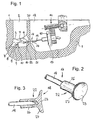
- Fig. 1 For the mechanical coupling of a mechanical oscillations excitable, in Fig. 1 only schematically indicated output side transducer portion 15 of the hearing aid 13 to a preselected Ankoppelstelle 16 on the ossicle chain 5, for example, to the "smooth" body of the anvil 7, from the mastoid side, is a biocompatible , mechanically passive coupling arrangement 17 is provided, which is connected to the actively oscillatable output-side converter part 15 and which rests in the implanted state with a remote from the hearing aid converter 13 Ankoppelende 18 at the coupling point 16. If an electrical voltage is applied to the hearing device converter 13, the coupling arrangement 17 is caused by means of the output-side converter part 15 to vibratory oscillations in the axial direction of the coupling arrangement.
- the audio signals recorded and electrically converted by an input-side converter (microphone) (not shown) on an electronic module in the hearing device directly lead to mechanical deflections of the coupling arrangement 17 after electronic amplification. These deflections correspond to the acoustic information.
- the deflections of the coupling arrangement 17 are forwarded to the ossicular chain of the middle ear or to the stapes or the oval or round window. They thus effect an audiological amplifying effect with appropriate design of the preprocessing electronic system.
- the coupling assembly 17 has in the illustrated embodiment, a mechanically fixedly connected to the output side transducer portion 15 coupling rod 19 which has the shape of a straight cylinder in the illustrated embodiment substantially along its entire length and in the implanted state of the mastoid cavity 12 by a in the the natural auditory canal (Aditus ad antrum) 21 located in the tympanic cavity 4 passes.
- To the coupling assembly 17 further includes a coupling element 22, which with the from the hearing device transducer 13 remote end of the coupling rod 19 is connected and the Ankoppelende 18 of the coupling assembly 17 forms.
- the Ankoppelende 18 has a contact surface 23 which has an adapted to the surface shape of the Ankoppelstelle 16 surface shape and such a surface finish and surface size, that it by applying the Ankoppelendes 18 to the Ankoppelstelle 16 to a dynamic train-pressure power coupling of coupling element 22 and Zielossikel (In the illustrated case the anvil 7) comes through a surface adhesion, which is sufficient for a play-free mutual connection of coupling element 22 and ossicle chain 5.
- the adhesion effect is supported by the fact that the middle ear space 4 always has 100% moisture and as a result a natural moisture film is present on the ossicles 6, 7, 9.
- the coupling element 22 is in its basic form corresponding to the Zielossikel or the locus of Zielossikels at the Ankoppelstelle 16 designed (concave, convex or plan) that it touches the ossicle without static bias or slight bias and a dynamic train-pressure power coupling caused due to the resulting adhesion.
- a desired static bias against the suspension bands of the middle ear can be generated by a suitable feed of the transducer 13 and thus the coupling rod 19 (corresponding to the double arrow 24 in Fig. 1) by means of the positioning and fixing system 14.
- Suitable positioning and fixing systems are described in US-A-5 788 711 and in the earlier EP patent application 99 122 684.6.
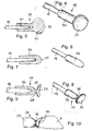
- the coupling element 22 which is shown on a larger scale in FIGS. 2 and 3, has a sleeve-shaped section 26 and a flange section 27 integrally connected thereto, which represents the coupling end 18 of the coupling arrangement 17, which is provided with a concave contact surface 23.
- the coupling element 22 is plugged with its sleeve-shaped portion 26 on the remote from the transducer 13 end of the coupling rod 19 and fixedly connected to the coupling rod, for example, crimped, welded, soldered or glued.
- a coupling element 29 is shown, which differs from the coupling element 22 only in that connects to a sleeve-shaped portion 30, a coupling end forming, spherical head 31.
- the head 31 has a larger diameter than the portion 30, and it has convexly curved contact surface 32.
- Figures 6 and 7 show a plugged onto the free end of the coupling rod 19 coupling element 34 with a substantially constant outer diameter and hemispherical Ankoppelende 35th
- the coupling element 37 illustrated in FIGS. 8, 9 and 10 is similar to the coupling element 22 of FIGS. 2 and 3. However, it additionally has a flexible intermediate element in the form of a constriction 38 at the transition point between the sleeve-shaped section 26 and the flange section 27. Depending on the material selected in the individual case for the coupling element and the dimensioning of the constriction 38, the contact surface 23 can thereby automatically adjust optimally to the coupling point 16 in the solid angle, or the coupling element can be plastically optimally plastically deformed individually by the surgeon intraoperatively.
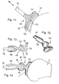
- a coupling element 40 in the case of the coupling element of FIGS. 2 and 3, has a relatively large-area flange section 41 with a concave contact surface 23.
- the concave contact surface 23 is a complementary convex curved surface 42 of a thin coupling plate 43 opposite, which is firmly connected in the example shown with the surface of the Anboß stressess.
- the dome plate 43 may, if necessary, be anatomically adapted.
- the coupling element 40 is butt-connected to the coupling rod 19. Instead, the free coupling rod end of a to the Flange portion 41 subsequent sleeve-shaped portion corresponding to Figures 5, 7 and 9 are received.
- a coupling element 46 is provided, in which a spherical receptacle 47 adjoins the flange 23 forming the contact surface 23.
- a ball seat 47 engages a ball head 48, which is part of a fixedly connected to the coupling rod 19 ball joint part 49.
- the consisting of the ball seat 47 and the ball joint part 49 ball joint 50 allows not only an adjustment of the solid angle of the contact surface 23 with respect to the longitudinal axis of the coupling rod 19, but in addition, a rotation of the coupling rod 19 relative to the coupling element 46.
- the ball joint part fixedly connected to the coupling rod 19 may be formed as a ball seat, which cooperates with a ball head, which is part of the coupling element. Furthermore, it may be possible to dispense with a separate intermediate part between the coupling rod and the coupling element by the ball head or the ball socket is formed directly on the coupling rod.
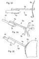
- Figures 15 to 18 show an embodiment in which between the coupling rod 19 and a coupling element 52, a flexible intermediate member 53 is inserted in the form of a separate component in order to adjust the solid angle of the contact surface 23 can.
- the coupling element 52 has a relatively large-area flange portion 54 with a connecting piece 55 which protrudes from the contact surface 23 opposite surface of the coupling element 52.
- the free end of the neck 55 is slightly convex and engages in a complementary recess 56 at one end of the intermediate member 53 a.
- the other end of the intermediate member 53 is connected to the coupling rod 19.
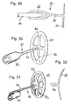
- a coil spring 60 which connects a flange portion 61 of the coupling element with the coupling rod 19.
- the ends of the helical spring 60 are at least non-positively connected to spring supports 63 and 64 of the coupling rod 19 and the flange portion 61.
- the spring 60 may optionally be made of a metal alloy with memory effect, in particular nitinol. Such a metal alloy can also be characterized by what is referred to as "superelasticity", that is to say that the transmitted force remains approximately the same in a certain range, even with different adjustment paths, as can be seen from the stress / strain diagram of FIG.
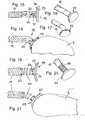
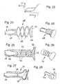
- FIGS. 23 to 28 Further possible spring elements are shown in FIGS. 23 to 28.
- a coupling element 71 is provided with a cylindrical section 72 which is inserted between a flange section 73 forming the contact surface 23 and a sleeve-shaped section 74.
- a series of circumferentially offset by 90 ° notches 75 are provided, whereby the cylindrical portion 72 are given spring characteristics.
- a sleeve-shaped section 78 merges into an arrangement of three spring clips 79 staggered in the circumferential direction.
- the coupling element 81 illustrated in FIGS. 29 and 30 has a sleeve-shaped section 82 which is connected to a planar adhesion element 84 via a slender shaft 83 concentric with the section 82.
- the adhesive member 84 has a perforated structure with an outer ring 85 and a plurality of spokes 86.
- the coupling element 88 of the embodiment of FIGS. 31 and 32 is provided with a perforated concave adhesive element 89.
- the adhesion element 89 is connected via a shaft 90 with a sleeve-shaped section 91 which can be pushed onto the coupling rod and which is attached laterally to the shaft 90.
- To the adhesive member 89 in turn include an outer ring 92 and a plurality of spokes 93.
- the outer rings 85, 92 may also be broken (slotted) for a better anatomical adjustment in a manner not shown.
- an adhesion element 96 has a plurality of protruding arms 97.
- the free ends 98 of the arms 97 together form the contact surface.
- the described coupling arrangement can in principle consist of any biocompatible materials, in particular metals, metal alloys and / or plastics.
- biocompatible materials in particular metals, metal alloys and / or plastics.
- titanium, gold, silver, niobium, tantalum, platinum, platinum-iridium, or alloys of these metals, implant steel, NiTi (nitinol) or other biocompatible memory molded metals may be considered as metallic materials.
- the plastics may, above all, be silicones, polyurethanes, PTFE, FEP, polycarbonates and the like. This broad selection, in particular of plastics, must be restricted accordingly if special material properties, such as plastic deformability for individual adaptation to the target ossicle, are required.
- the total mass of the coupling arrangement should preferably be below the mass of the anvil, which is on average 25 mg.
- a lowest possible weight of the coupling arrangement also leads to the reduction of inertial forces during acceleration by external influences such as impact, vibration and the like.
Abstract
Description
Die Erfindung betrifft eine Vorrichtung zum mechanischen Ankoppeln eines zu mechanischen Schwingungen anregbaren ausgangsseitigen Wandlerteils eines außerhalb des Mittelohrbereiches in einer artifiziellen Mastoidhöhle implantierbaren elektromechanischen Hörgerätewandlers an eine vorgewählte Ankoppelstelle an der Ossikelkette, der Steigbügelfußplatte oder einer das runde Fenster oder ein artifizielles Fenster in der Cochlea, im Vestibulum oder im Labyrinth (Gleichgewichtsorgan) abschließenden Membran, mit einer biokompatiblen, mechanisch passiven Koppelanordnung, die mit dem ausgangsseitigen Wandlerteil verbunden ist und die im implantierten Zustand von der Mastoidhöhle in die Paukenhöhle reicht sowie mit einem von dem Hörgerätewandler abliegenden Ankoppelende an der Ankoppelstelle anliegt.The invention relates to a device for mechanically coupling an output - side converter part, which can be stimulated to mechanical vibrations, to a preselected coupling point on the ossicular chain, the stapes foot plate or the round window or an artificial window in the cochlea, in the artificial limb in an artificial mastoid cavity Vestibulum or in the labyrinth (equilibrium organ) final membrane, with a biocompatible, mechanically passive coupling arrangement which is connected to the output side transducer part and which extends in the implanted state of the mastoid into the tympanic cavity and rests with a remote from the hearing aid transducer Ankoppelende at the Ankoppelstelle.
Elektronische Maßnahmen zur Rehabilitation eines operativ nicht behebbaren Innenohrschadens haben heute einen wichtigen Stellenwert erreicht. Bei totalem Ausfall des Innenohres sind Cochlea Implantate mit direkter elektrischer Reizung des verbleibenden Hörnerven im routinemäßigen klinischen Einsatz. Bei mittleren bis schweren Innenohrschäden kommen derzeit erstmals volldigitale Hörgeräte zur Anwendung, die eine neue Welt der elektronischen Audiosignalverarbeitung eröffnen und erweiterte Möglichkeiten der gezielten audiologischen Feinanpassung der Hörgeräte an den individuellen Innenohrschaden bieten. Trotz dieser in den letzten Jahren erreichten, erheblichen Verbesserungen der apparativen Hörgeräteversorgung bleiben bei konventionellen Hörgeräten grundsätzliche Nachteile bestehen, die durch das Prinzip der akustischen Verstärkung bedingt sind, das heißt insbesondere durch die Rückwandlung des elektronisch verstärkten Signals in Luftschall. Zu diesen Nachteilen zählen Aspekte wie die Sichtbarkeit der Hörgeräte, mangelnde Klangqualität aufgrund der elektromagnetischen Wandler (Lautsprecher), verschlossener äußerer Gehörgang sowie Rückkoplungseffekte bei hoher akustischer Verstärkung.Electronic measures for the rehabilitation of surgically irrecoverable inner ear damage have reached an important status today. In case of total failure of the inner ear, cochlear implants with direct electrical stimulation of the remaining auditory nerve are in routine clinical use. In the case of moderate to severe inner ear damage, fully digital hearing aids are being used for the first time, opening up a new world of electronic audio signal processing and offering extended options for the targeted audiological fine adjustment of the hearing aids to the individual inner ear damage. Despite this achieved in recent years, significant improvements in the equipment hearing aid supply remain conventional in conventional hearing aids Disadvantages exist that are caused by the principle of acoustic amplification, that is, in particular by the reconversion of the electronically amplified signal in airborne sound. These disadvantages include aspects such as the visibility of the hearing aids, lack of sound quality due to the electromagnetic transducer (loudspeaker), closed outer ear canal and feedback effects with high acoustic amplification.
Aufgrund dieser prinzipiellen Nachteile besteht seit langem der Wunsch, von konventionellen Hörgeräten mit akustischer Anregung des geschädigten Innenohres abzukommen und diese Geräte durch teil- oder vollimplantierbare Hörsysteme mit einer direkten mechanischen Stimulation zu ersetzen. Implantierbare Hörsysteme unterscheiden sich von konventionellen Hörgeräten: zwar wird das Schallsignal mit einem Wandler (Mikrofon) in ein elektrisches Signal umgewandelt und in einer elektronischen Signalverarbeitungsstufe verstärkt; dieses verstärkte elektrische Signal wird jedoch nicht einem elektroakustischen Wandler (Lautsprecher) zugeführt, sondern einem implantierten elektromechanischen Wandler, dessen ausgangsseitige mechanische Schwingungen unmittelbar, also mit direktem mechanischen Kontakt, dem Mittel- beziehungsweise Innenohr zugeführt werden oder mittelbar durch einen Kraftschluß über einen Luftspalt bei zum Beispiel elektromagnetischen Wandlersystemen. Dieses Prinzip gilt unabhängig von einer teilweisen oder vollständigen Implantation aller notwendigen Systemelemente sowie auch unabhängig davon, ob eine reine Innenohrschwerhörigkeit bei vollständig intaktem Mittelohr oder eine kombinierte Schwerhörigkeit (Mittel- und Innenohr geschädigt) rehabilitiert werden soll. Daher sind in der jüngeren wissenschaftlichen Literatur sowie in zahlreichen Patentschriften implantierbare elektromechanische Wandler sowie Verfahren zur direkten Ankopplung der mechanischen Wandlerschwingungen an das intakte Mittelohr beziehungsweise das Innenohr zur Rehabilitation einer reinen Innenohrschwerhörigkeit sowie auch an verbleibende Ossikel des Mittelohres bei artifiziell oder pathologisch verändertem Mittelohr zur Versorgung einer Schalleitungsschwerhörigkeit sowie deren Kombinationen beschrieben worden.Because of these principal disadvantages has long been the desire to come off conventional hearing aids with acoustic stimulation of the damaged inner ear and replace these devices with partially or fully implantable hearing with direct mechanical stimulation. Implantable hearing systems differ from conventional hearing aids: the sound signal is converted into an electrical signal with a transducer (microphone) and amplified in an electronic signal processing stage; However, this amplified electrical signal is not supplied to an electro-acoustic transducer (speaker), but an implanted electromechanical transducer whose output side mechanical vibrations directly, ie with direct mechanical contact, the middle or inner ear are fed or indirectly by a frictional connection via an air gap at Example of electromagnetic transducer systems. This principle applies regardless of a partial or complete implantation of all necessary system elements as well as regardless of whether a pure inner ear hearing loss in completely intact middle ear or a combined deafness (middle and inner ear damaged) to be rehabilitated. Therefore, in the recent scientific literature and in numerous patents implantable electromechanical transducers and methods for direct coupling of the mechanical transducer oscillations to the intact middle ear or the inner ear for the rehabilitation of a pure inner ear hearing and also to remaining ossicles of the middle ear in artificially or pathologically altered middle ear to supply a Conductive deafness and their combinations have been described.
Als elektromechanisches Wandlerverfahren kommen grundsätzlich alle physikalischen Wandlungsprinzipien in Frage wie elektromagnetisch, elektrodynamisch, magnetostriktiv, dielektrisch und piezoelektrisch. Verschiedene Forschungsgruppen haben sich in den letzten Jahren im wesentlichen auf zwei dieser Verfahren konzentriert: elektromagnetisch und piezoelektrisch. Eine Übersicht über diese Wandlervarianten findet sich bei Zenner und Leysieffer (HNO 1997 Vol. 45, 749 - 774).In principle, all physical conversion principles such as electromagnetic, electrodynamic, magnetostrictive, dielectric and piezoelectric are suitable as the electromechanical transducer method. Several research groups have focused on two of these methods in recent years: electromagnetically and piezoelectrically. An overview of these converter variants can be found in Zenner and Leysieffer (HNO 1997 Vol. 45, 749 - 774).
Beim piezoelektrischen Verfahren ist eine mechanisch direkte Kopplung der ausgangsseitigen Wandlerschwingungen an die Mittelohrossikel oder direkt an das ovale Fenster notwendig. Beim elektromagnetischen Prinzip kann die Kraftkopplung einerseits über einen Luftspalt erfolgen ("kontaklos"), das heißt, nur ein Permanentmagnet wird durch dauerhafte Fixation in direkten mechanischen Kontakt mit einem Mittelohrossikel gebracht. Andererseits besteht die Möglichkeit, den Wandler vollständig in einem Gehäuse zu realisieren (wobei Spule und Magnet mit kleinstmöglichem Luftspalt gekoppelt sind) und die ausgangsseitigen Schwingungen über ein mechanisch steifes Koppelelement mit direktem Kontakt auf die Mittelohrossikel zu übertragen (Leysieffer et al. 1997 (HNO 1997, Vol. 45, pp. 792-800)).In the piezoelectric method, a mechanically direct coupling of the output-side transducer oscillations to the middle ossicles or directly to the oval window is necessary. In the electromagnetic principle, the power coupling on the one hand via an air gap can be done ("contactless"), that is, only a permanent magnet is brought by permanent fixation in direct mechanical contact with a Mittelohrossikel. On the other hand, it is possible to completely realize the converter in a housing (coil and magnet being coupled with the smallest possible air gap) and to transmit the output oscillations via a mechanically rigid coupling element with direct contact to the central ossicles (Leysieffer et al., 1997 (HNO 1997) , Vol. 45, pp. 792-800)).
In der Patentliteratur finden sich einige der oben genannten Realisierungsvarianten sowohl elektromagnetischer wie auch piezoelektrischer Hörgerätewandler: US-A-5 707 338 (Adams et al.), WO 98/06235 (Adams et al.), WO 98/06238 (Adams et al.), WO 98/06236 (Kroll et al.), WO 98/06237 (Bushek et al.), US-A-5 554 096 (Ball), US-A-3 712 962 (Epley), US-A-3 870 832 (Fredrickson), US-A-5 277 694 (Leysieffer et al.), EP-A-0 984 663 (Leysieffer), EP-A-0 984 665 (Leysieffer), US-A-5 015 224 (Maniglia), US-A-3 882 285 (Nunley), US-A-4 850 962 (Schaefer).Some of the above implementation variants of both electromagnetic and piezoelectric hearing aid transducers can be found in the patent literature: US Pat. No. 5,707,338 (Adams et al.), WO 98/06235 (Adams et al.), WO 98/06238 (Adams et al ), WO 98/06236 (Kroll et al.), WO 98/06237 (Bushek et al.), US-A-5 554 096 (Ball), US-A-3 712 962 (Epley), US-A -3 870 832 (Fredrickson), US-A-5 277 694 (Leysieffer et al.), EP-A-0 984 663 (Leysieffer), EP-A-0 984 665 (Leysieffer), US-A-5 015 224 (Maniglia), US-A-3,882,285 (Nunley), US-A-4,850,962 (Schaefer).
Das teilimplantierbare, piezoelektrische Hörsystem der japanischen Gruppe um Suzuki und Yanigahara setzt für eine Implantation des Wandlers das Fehlen der Mittelohrossikel und eine freie Paukenhöhle voraus, um das Piezoelement an den Stapes ankoppeln zu können (Yanigahara et al.: Efficacy of the partially implantable middle ear implant in middle and inner ear disorders. Adv. Audiol.., Vol. 4, Karger Basel (1988), pp. 149-159; Suzuki et al.: Implantation of partially implantable middle ear implant and the indication. Adv. Audiol., Vol. 4, Karger Basel (1988), pp. 160-166). Ebenso wird bei dem Verfahren eines implantierbaren Hörsystems für Innenohrschwerhörige nach US-A-4 850 962 (Schaefer) grundsätzlich der Amboß entfernt, um ein piezoelektrisches Wandlerelement an den Stapes ankoppeln zu können. Dies gilt im wesentlichen auch für weitere Entwicklungen, die auf der SCHAEFER-Technologie basieren und in den oben genannten Patentschriften dokumentiert sind (US-A-5 707 338, WO 98/06235, WO 98/06238, WO 98/06236, WO 98/06237).The semi-implantable, piezoelectric hearing system of the Japanese group of Suzuki and Yanigahara requires the lack of Mittelohrossikel and a free tympanic cavity for an implantation of the transducer in order to couple the piezoelectric element to the stapes can (Yanigahara et al .: Efficacy of the partially implantable middle ear implant in middle and inner ear disorders Adv. Audiol., Vol. 4, Karger Basel (1988), pp. 149-159; Suzuki et al .: Implantation of partially implantable middle ear implant and the indication. Adv. Audiol., Vol. 4, Karger Basel (1988), p. 160-166). Similarly, in the method of an implantable hearing aid for inner ear hearing loss according to US-A-4,850,962 (Schaefer) basically the anvil is removed in order to couple a piezoelectric transducer element to the stapes can. This also applies essentially to further developments based on SCHAEFER technology and documented in the abovementioned patents (US Pat. No. 5,707,338,
Der elektromagnetische Wandler nach Ball ("Floating Mass Transducer FMT", US-A-5 624 376, US-A-5 554 096) wird dagegen bei intaktem Mittelohr mit Titanclips direkt an dem langen Fortsatz des Amboß fixiert. Der elektromagnetische Wandler des teilimplantierbaren Systems nach FREDRICKSON (Fredrickson et al.: Ongoing investigations into an implantable elektromagnetic hearing aid for moderate to severe sensorineural hearing loss. Otolaryngologic Clinics Of Nord America, Vol. 28/1 (1995), pp. 107-121) wird bei ebenfalls intakter Ossikelkette des Mittelohres mechanisch direkt an den Amboßkörper gekoppelt. Das Gleiche gilt für die piezoelektrischen und elektromagnetischen Wandler nach LEYSIEFFER (Leysieffer et al.: Ein implantierbarer piezoelektrischer Hörgerätewandler für Innenohrschwerhörige. HNO 1997/45, pp. 792-800, US-A-5 277 694, EP-A-0 984 663, EP-A-0 984 665). Auch bei dem elektromagnetischen Wandlersystem nach MANIGLIA (Maniglia et al.: Contactless semi-implantable electromagnetic middle ear device for the treatment of sensorineural hearing loss, Otolaryngologic Clinics Of Nord America, Vol. 28/1 (1995), pp. 121-141) wird bei intakter Ossikelkette ein Permanentmagnet mechanisch an der Ossikelkette dauerhaft fixiert, der jedoch über eine Luftspaltkopplung von einer Spule mechanisch angetrieben wird.By contrast, the ball-type electromagnetic transducer ("Floating Mass Transducer FMT", US Pat. No. 5,624,376, US Pat. No. 5,554,096) is fixed directly to the long projection of the anvil with the middle ear intact with titanium clips. The electromagnetic transducer of the partially implantable FREDRICKSON system (Fredrickson et al .: Ongoing investigations into an implantable electro-magnetic hearing aid for moderate to severe sensorineural hearing loss, Otolaryngologic Clinics of North America, Vol. 28/1 (1995), pp. 107-121 ) is mechanically coupled directly to the anvil body with also intact ossicular chain of the middle ear. The same applies to the LEYSIEFFER piezoelectric and electromagnetic transducers (Leysieffer et al .: An implantable piezoelectric hearing aid transducer for people with inner ear hearing loss, HNO 1997/45, pp. 792-800, US Pat. No. 5,277,694, EP-A-0 984 663 , EP-A-0 984 665). Also in the MANIGLIA electromagnetic transducer system (Maniglia et al .: Contactless Semi-Implantable Electromagnetic Device, Otolaryngologic Clinic of North America, Vol. 28/1 (1995), pp. 121-141) In the case of an intact ossicle chain, a permanent magnet is permanently fixed mechanically to the ossicular chain, but it is mechanically driven by a coil via an air gap coupling.
Bei den beschriebenen Wandler- und Ankopplungsvarianten sind grundsätzlich zwei Implantationsprinzipien zu unterscheiden:
- a) Im Falle des einen Prinzips befindet sich der elektromechanische Wandler mit seinem aktiven Wandlerelement selbst im Mittelohrbereich in der Paukenhöhle, und der Wandler ist dort mit einem Ossikel oder dem Innenohr direkt verbunden (US-A-4 850 962, US-A-5 015 225, US-A-5 707 338, WO 98/06235, WO 98/06238, WO 98/06236, WO 98/06237, US-A-5 624 376, US-A-5 554 096).
- b) Bei dem anderen Prinzip befindet sich der elektromechanische Wandler mit seinem aktiven Wandlerelement außerhalb des Mittelohrbereiches in einer artifiziell geschaffenen Mastoidhöhle. Die ausgangsseitigen mechanischen Schwingungen werden dann mittels mechanisch passiver Koppelelemente über geeignete operative Zugänge (natürlicher aditus ad antrum, Eröffnung des chorda-facialis-Winkels oder über eine artifizielle Bohrung vom Mastoid aus) zum Mittel- oder Innenohr übertragen (Fredrickson et al.: Ongoing investigations into an implantable elektromagnetic hearing aid for moderate to severe sensorineural hearing loss. Otolaryngologic Clinics Of Nord America, Vol. 28/1 (1995), pp. 107-121; DE-B-41 04 358.8; EP-A-0 984 663; EP-A-0 984 665).
- a) In the case of the one principle, the electromechanical transducer with its active transducer element is located even in the middle ear region in the tympanic cavity, and the transducer is directly connected there to an ossicle or the inner ear (US Pat. No. 4,850,962, US Pat 015,225, US-A-5,707,338, WO98 / 06235, WO98 / 06238, WO98 / 06236, WO98 / 06237, US-A-5,624,376, US-A-5,554,096).
- b) In the other principle, the electromechanical transducer with its active transducer element is located outside the middle ear area in an artificially created mastoid cavity. The mechanical vibrations on the output side are then transmitted to the middle or inner ear via mechanically passive coupling elements via suitable operative approaches (natural aditus ad antrum, opening of the chorda facialis angle or via an artificial bore from the mastoid) (Fredrickson et al .: Ongoing investigations Otolaryngologic Clinics Of North America, Vol. 28/1 (1995), pp. 107-121; DE-B-41 04 358.8; EP-A-0 984 663 EP-A-0 984 665).
Bei den Varianten nach a) kann der Wandler als sogenannter "Floating Mass"-Wandler ausgeführt sein, das heißt, das Wandlerelement benötig keine "Reaktio" über eine feste Verschraubung mit dem Schädelknochen, sondern es schwingt aufgrund von Massenträgheitsgesetzen mit seinem Wandlergehäuse und überträgt diese direkt auf ein Mittelohrossikel (US-A-5 624 376, US-A-5 554 096, US-A-5 707 338, WO 98/06236). Dies bedeutet einerseits, daß vorteilhaft auf ein implantierbares Fixationssystem an der Schädelkalotte verzichtet werden kann; andererseits bedeutet diese Variante nachteilig, daß voluminöse artifizielle Elemente in die Paukenhöhle eingebracht werden müssen und deren Langzeit- und Biostabilität insbesondere bei temporären pathologischen Veränderungen des Mittelohres (z.B. otitis media) heute nicht bekannt beziehungsweise gewährleistet sind. Ein weiterer wesentlicher Nachteil besteht darin, daß die Wandler vom Mastoid aus mit ihrer elektrischen Zuleitung ins Mittelohr gebracht und dort mit Hilfe geeigneter operativer Werkzeuge fixiert werden müssen; dies erfordert einen erweiterten Zugang durch den chorda-facialis-Winkel und bringt somit eine latente Gefährdung des in unmittelbarer Nachbarschaft gelegenen Gesichtsnerven (nervus facialis) mit sich.In the variants according to a), the converter can be designed as a so-called "floating mass" converter, that is, the transducer element does not require "Reactio" via a fixed screw with the skull bone, but it oscillates due to inertia laws with its transducer housing and transmits them directly onto a middle ossicle (US-A-5,624,376, US-A-5 554 096, US-A-5 707 338, WO 98/06236). This means, on the one hand, that it is advantageously possible to dispense with an implantable fixation system on the skullcap; On the other hand, this variant is disadvantageous in that voluminous artificial elements must be introduced into the tympanic cavity and their long-term and biostability, especially in temporary pathological changes of the middle ear (eg otitis media) are not known or guaranteed today. Another significant disadvantage is that the converter must be brought from the mastoid with their electrical supply line in the middle ear and fixed there with the aid of suitable surgical tools; this requires extended access through the Chorda facialis angle and thus brings a latent threat to the nearby facial nerves (facial nerve) with it.
Bei den Wandlervarianten nach b) muß das Wandlergehäuse mit implantierbaren Positionier- und Fixationssystemen an der Schädelkalotte befestigt werden (vorteilhafte Ausführung DE-A-196 18 964 entsprechend US-A-5 788 711). Ein Nachteil der Varianten nach b) besteht darin, daß eine Vertiefung in die Zielossikel, vorzugsweise mittels geeigneter Laser, eingebracht werden muß, um das Koppelelement applizieren zu können. Dies ist einerseits technisch aufwendig und teuer und bringt andererseits Risiken für den Patienten mit sich. Sowohl bei dem teilimplantierbaren System nach FREDRICKSON (Ongoing investigations into an implantable elektromagnetic hearing aid for moderate to severe sensorineural hearing loss. Otolaryngologic Clinics Of Nord America, Vol. 28/1 (1995), pp. 107-121) wie auch bei dem vollimplantierbaren Hörsystem nach LEYSIEFFER und ZENNER (HNO 1998, Vol. 46, 853-863 und 844-852) wird bei der Ankopplung des schwingenden Wandlerteils an den Amboßkörper zur dauerhaften und mechanisch sicheren Schwingungsübertragung davon ausgegangen, daß die Spitze der Koppelstange, die in die laserinduzierte Vertiefung des Mittelohrossikels eingebracht wird, langfristig eine Osseointegration erfährt, das heißt, die Koppelstange verwächst fest mit dem Ossikel und gewährleistet so eine sichere Übertragung dynamischer Druck- und Zugkräfte. Dieser Langzeiteffekt ist zur Zeit jedoch noch nicht wissenschaftlich nachgewiesen beziehungsweise gesichert. Weiterhin besteht bei dieser Ankopplungsart bei einem technischen Wandlerdefekt der Nachteil, daß eine Entkopplung vom Ossikel zur Entfernung des Wandlers nur mit mechanisch basierten operativen Methoden vorgenommen werden kann, was eine erhebliche Gefährdung des Mittelohres und insbesondere des Innenohres bedeuten kann.In the converter variants according to b), the converter housing with implantable positioning and fixation systems must be fastened to the skull (advantageous embodiment DE-A-196 18 964 corresponding to US Pat. No. 5,788,711). A disadvantage of the variants according to b) is that a depression in the Zielossikel, preferably by means of suitable laser, must be introduced in order to apply the coupling element can. On the one hand, this is technically complicated and expensive, and on the other hand it entails risks for the patient. Both in the partially implantable system according to FREDRICKSON (Ongoing investigations into an implantable electromagnetic hearing aid for moderate to severe sensorineural hearing loss, Otolaryngologic Clinics of North America, Vol. 28/1 (1995), pp. 107-121) as well as in the fully implantable The hearing system according to LEYSIEFFER and ZENNER (HNO 1998, Vol. 46, 853-863 and 844-852) is based on the coupling of the oscillating transducer part to the anvil body for permanent and mechanically safe vibration transmission assumed that the tip of the coupling rod, which in the laser-induced Deepening of Mittelohrossikels is introduced long-term osseointegration undergoes, that is, the coupling rod fuses firmly with the ossicle, thus ensuring a secure transmission of dynamic pressure and tensile forces. This long-term effect is currently not scientifically proven or secured. Furthermore, there is the disadvantage in this type of coupling in a technical converter defect that decoupling of the ossicle to remove the transducer can only be made with mechanically based surgical methods, which can mean a significant threat to the middle ear and in particular the inner ear.
Der wesentliche Vorteil dieser Wandlerausführungsformen nach b) besteht jedoch darin, daß das Mittelohr weitgehend frei bleibt und der Koppelzugang zum Mittelohr ohne größeres Gefährdungspotential des nervus facialis erfolgen kann. Ein vorzugsweises operatives Verfahren hierzu ist in der US-Patentanmeldung 09/168.079 beschrieben. Grundlegende vorteilhafte Formen passiver Koppelelemente zur Übertragung der ausgangsseitigen Wandlerschwingungen vom Mastoid aus zum Mittel- beziehungsweise Innenohr sind in EP-A-0 499 940 (entsprechend US-A-5 277 964), in EP-A-0 901 779 (entsprechend US 09/042.805) und in HNO 1998 Vol. 46, 27 - 37 - Lehner et al.: "Kaltfließende Elemente zur Ankopplung eines implantierbaren Hörgerätewandlers an Gehörknöchelchen oder Perilymphe" beschrieben. Dabei handelt es sich insbesondere um Koppelelemente aus Gold, vorzugsweise weichgeglühtem Feingold, in Form eines C-Bandes für den langen Amboßfortsatz, einer Bandschlaufe für den langen Amboßfortsatz und eines Glöckchens für das Steigbügelköpfchen, wobei sich diese Koppelelemente unter Verwendung von ohrchirurgischen Standardinstrumenten ankoppeln und erforderlichenfalls auch wieder lösen lassen.The main advantage of this converter embodiments according to b), however, is that the middle ear remains largely free and the coupling access to the middle ear can be done without greater risk potential of the facial nerve. A preferred operative method for this is described in U.S. Patent Application 09 / 168,079. Basic advantageous forms of passive coupling elements for transmitting the output side transducer oscillations from the mastoid to the middle or inner ear are described in EP-A-0 499 940 (corresponding to US Pat. No. 5,277,964), in EP-A-0 901 779 (corresponding to US Pat. 042.805) and in ENT 1998 Vol. 46, 27 - 37 - Lehner et al.: "Cold-flowing elements for coupling an implantable hearing aid transducer to auditory ossicles or perilymph" described. These are in particular coupling elements made of gold, preferably soft annealed fine gold, in the form of a C-band for the long anvil process, a band loop for the long anvil process and a bell for the Stirruphead, with these coupling elements coupling using standard surgical ear instruments and, if necessary also let solve again.
Der vorliegenden Erfindung liegt die Aufgabe zugrunde, eine Vorrichtung zum Ankoppeln eines Hörgerätewandlers und zur Übertragung der ausgangsseitigen Wandlerschwingungen an das Mittel- beziehungsweise Innenohr zu schaffen, die unter Beibehaltung der genannten Vorteile der Variante b) einfacher und sicherer applizierbar ist, die während der Implantation im Innenohr notwendige, risikobehaftete Arbeiten minimiert und auch ein unter Umständen später notwendig werdendes Entkoppeln erleichtert sowie eine optimale Schwingungsform der Steigbügelfußplatte begünstigt.The present invention has for its object to provide a device for coupling a hearing aid transducer and the transmission of the output side transducer oscillations to the middle or inner ear, while maintaining the advantages of the variant b) easier and safer to apply, during implantation in the Inner ear necessary, risky work minimized and also facilitates a possibly later becoming decoupling easier and favors an optimal waveform of Stirrupfußplatte.
Ausgehend von einer Vorrichtung der aus EP-A-0 901 779 und HNO 1998 Vol. 46, 27-37 bekannten Art, das heißt einer Vorrichtung zum mechanischen Ankoppeln eines zu mechanischen Schwingungen anregbaren ausgangsseitigen Wandlerteils eines außerhalb des Mittelohrbereiches in einer artifiziellen Mastoidhöhle implantierbaren elektromechanischen Hörgerätewandlers an eine vorgewählte Ankoppelstelle an der Ossikelkette, der Steigbügelfußplatte oder einer das runde Fenster oder ein artifizielles Fenster abschließenden Membran, mit einer biokompatiblen, mechanisch passiven Koppelanordnung, die mit dem ausgangsseitigen Wandlerteil verbunden ist und die im implantierten Zustand von der Mastoidhöhle in die Paukenhöhle reicht sowie mit einem von dem Hörgerätewandler abliegenden Ankoppelende an der Ankoppelstelle anliegt, wird diese Aufgabe erfindungsgemäß dadurch gelöst, daß das Ankoppelende von einem Koppelelement mit einer Kontaktfläche gebildet ist, die eine an die Oberflächenform der Ankoppelstelle anpaßbare oder angepaßte Oberflächenform sowie eine solche Oberflächenbeschaffenheit und Oberflächengröße aufweist, daß es durch Anlegen des Ankoppelendes an die Ankoppelstelle zu einer dynamischen Zug-Druck-Kraftkopplung von Koppelelement und Ossikelkette durch Oberflächenadhäsion kommt, die für eine sichere gegenseitige Verbindung von Koppelelement und Ossikelkette ausreicht.Starting from a device of the type known from EP-A-0 901 779 and HNO 1998 Vol. 46, 27-37, that is a device for mechanical coupling of an excitable to mechanical vibrations output side transducer part of an outside of the middle ear area in an artificial mastoid cavity implantable electromechanical Hearing aid transducer to a preselected coupling site on the ossicle chain, the Stirrupfußplatte or a round window or an artificial window final membrane, with a biocompatible, mechanically passive coupling assembly which is connected to the output side transducer part and which extends in the implanted state of the mastoid into the tympanic cavity and abuts the coupling point with a coupling end remote from the hearing device transducer, this object is achieved in that the Ankoppelende is formed by a coupling element with a contact surface having an adaptable to the surface shape of the coupling point or adapted surface shape and such a surface finish and surface size, that it by applying the Ankoppelendes to the coupling point to a dynamic Tension-pressure force coupling of coupling element and ossicle chain by surface adhesion comes, which is sufficient for a secure mutual connection of coupling element and ossicle chain.
Die Vorrichtung nach der Erfindung sorgt für eine Ankopplung des ausgangsseitigen Wandlerteils eines in einer Mastoidhöhle implantierbaren elektromechanischen Hörgerätewandlers an ein Ossikel (Hammer, Amboß, Steigbügel; bevorzugt Amboß), an die Steigbügelfußplatte oder an eine das runde Fenster oder ein artifizielles Fenster abschließende Membran durch Oberflächenadhäsion. Unter dem Begriff "Oberflächenadhäsion" ist vorliegend eine Haftung unter dem Einfluß der bei hinreichend starker Annäherung an den Berührungsflächen wirksam werdenden molekularen Anziehungskräfte oder eine gegenseitige mechanische Verblockung der Berührungsflächen ohne den Einsatz eines Klebstoffes oder Zements zu verstehen. Zu einer entsprechenden Flächenhaftung können auch Luftblasen beitragen, die in Oberflächenvertiefungen eingeschlossen sind. Werden die Berührungsflächen Kräften ausgesetzt, welche die Flächen zu trennen suchen, erzeugen solche Luftblasen eine Saugwirkung, was die Trennung erheblich erschwert (Bild der Wissenschaft, April 1999, S. 10).The device according to the invention provides for a coupling of the output-side transducer part of an electromechanical hearing aid transducer implantable in a mastoid cavity to an ossicle (hammer, anvil, stirrup, preferably anvil), to the stapes footplate or to a membrane terminating the round window or an artificial window by surface adhesion , In the present context, the term "surface adhesion" is to be understood as meaning adhesion under the influence of the molecular attractive forces acting on a sufficiently strong approach to the contact surfaces or mutual mechanical blocking of the contact surfaces without the use of an adhesive or cement. Air bubbles that are trapped in surface depressions can also contribute to a corresponding surface adhesion. If the contact surfaces are exposed to forces that seek to separate the surfaces, such air bubbles create a suction effect, which makes the separation considerably more difficult (Bild der Wissenschaft, April 1999, p. 10).
Ein grundlegender Vorteil einer solchen Adhäsionskopplung besteht darin, daß die Ankoppelstelle zum Beispiel des Ossikels nicht hauptsächlich in Schwingungsrichtung des antreibenden Wandlers "zwangsgeführt" wird, wobei eine solche "Zwangsführung" zu einer nichtoptimalen Schwingungsform der Steigbügelfußplatte im ovalen Fenster führen kann. (Eine vorzugsweise Schwingungsform ist eine kolbenförmige Schwingung der Steigbügelfußplatte senkrecht zu ihrer Ebene.) Vielmehr stellt das Ossikel bei Nutzung der Oberflächenadhäsionskopplung seine (frequenzabhängige) Schwingungsrichtung aufgrund der dynamischen Eigenschaften des intakten Mittelohres selbst ein. Dieser Vorteil gilt auch bei nicht-intakter, (teil-)abgebauter Ossikelkette und Ankopplung an den dem Innenohr zugewandten "Rest" der Kette, und im Extremfall auch bei nur verbleibendem Steigbügel oder nur Steigbügelfußplatte, da diese(r) durch das sogenannte Ligament (ein elastisches Ringband, das den Steigbügel im ovalen Fenster "hält") aufgehängt ist. Darüberhinaus ist eine postoperative Lösbarkeit der Ossikelankopplung auch noch nach mehrjähriger Körperverweilzeit gegeben. Eine solche Lösung der Verbindung ist mit adäquatem Kraftaufwand und unter Verwendung von ohrchirurgischen Standardinstrumenten möglich.A fundamental advantage of such an adhesion coupling is that the coupling site of, for example, the ossicle is not "forced" primarily in the direction of vibration of the driving transducer, such "constraining" may result in a non-optimal waveform of the stapes foot plate in the oval window. (A preferred mode of vibration is a piston-shaped oscillation of the stirrup base plate perpendicular to its plane.) Rather, the ossicle, when using the surface adhesion coupling, sets its (frequency-dependent) direction of oscillation due to the dynamic properties of the intact middle ear itself. This advantage also applies to non-intact, (partially) degraded ossicular chain and coupling to the inner ear facing "remainder" of the chain, and in extreme cases even with only remaining stirrup or stirrup sole plate, as this (r) by the so-called ligament ( an elastic ring band which "holds" the stirrup in the oval window) is suspended. In addition, a postoperative solubility of the ossicle coupling is still given after several years Körperverweilzeit. Such a solution of the connection is possible with adequate effort and using standard surgical ear instruments.
Es ist zwar bei einer externen (nicht implantierbaren) Hörhilfe mit elektromagetischem Ausgangswandler bekannt (EP-B-0 556 300), auf nicht invasivem Wege einen Permanentmagneten des Ausgangswandlers mittels manuell lösbarer Oberflächenhaftung an der Außenfläche des Trommelfells zu halten. In diesem Fall spielen aber Probleme, wie eine nicht optimale Schwingungsform der Steigbügelfußplatte durch Zwangsführung eines Ossikels und risikobehaftetes Arbeiten im Innenohr während einer Implantation, keine Rolle. Außerdem ist die an der Außenfläche des Trommelfells zur Verfügung stehende große Fläche nicht vergleichbar mit den winzigen Ankoppelflächen im Mittelohr.While it is known in an external (non-implantable) hearing aid with electromagetic output transducer (EP-B-0 556 300) to hold a non-invasive way a permanent magnet of the output transducer by means of manually releasable surface adhesion to the outer surface of the eardrum. In this case, however, problems such as a non-optimal vibration form of the stirrup footplate due to the positive guidance of an ossicle and risky working in the inner ear during an implantation play no role. In addition, the large area available on the outer surface of the eardrum is not comparable to the tiny coupling surfaces in the middle ear.
Daneben ist eine passive Ossikelprothese mit einem Kopf, einem Schaft und einem biegbaren Zwischenstück bekannt (WO 90/11737). Das Zwischenstück erlaubt es, die Winkelausrichtung des Schafts mit Bezug auf den Kopf einzustellen. Bei implantierter Prothese stützt sich der Schaft an dem Steigbügelbogen, einem Steigbügelschenkel oder der Steigbügelfußplatte ab, während der Prothesenkopf am Trommelfell oder am Hammer unter einer solchen Vorspannung anliegt, daß das Trommelfell leicht gespannt wird. Die infolgedessen von dem Trommelfell auf die Prothese ausgeübte Druckkraft hält die Prothese an Ort und Stelle. Der Kopf und der Schaft der Prothese sind vorzugsweise aus Hydroxylapatit oder aus einem Gemisch von Hydroxylapatitteilchen und Silkon oder Polyurethan gefertigt. An einem solchen Werkstoff haftet menschliches Gewebe an, wodurch die Festlegung der Prothese im Mittelohr unterstützt werden soll.In addition, a passive ossicle prosthesis with a head, a shaft and a bendable intermediate piece is known (WO 90/11737). The intermediate piece makes it possible to adjust the angular orientation of the shaft with respect to the head. In the case of an implanted prosthesis, the shaft is supported on the stapes arch, stapes leg or stapes foot plate while the prosthetic head rests against the eardrum or hammer under such bias that the eardrum is slightly tensioned. As a result, the compressive force exerted by the eardrum on the prosthesis holds the prosthesis in place. The head and stem of the prosthesis are preferably made of hydroxyapatite or a mixture of hydroxyapatite particles and silicone or polyurethane. Human tissue adheres to such a material, which is intended to support the fixation of the prosthesis in the middle ear.
Bevorzugte weitere Ausgestaltungen der Erfindung ergeben sich aus den Unteransprüchen.Preferred further embodiments of the invention will become apparent from the dependent claims.
Insbesondere weist die Koppelanordnung zweckmäßig eine mit dem ausgangsseitigen Wandlerteil fest verbundene, im implantierten Zustand von der Mastoidhöhle in die Paukenhöhle reichende Koppelstange und ein Koppelelement auf, das mit dem von dem ausgangsseitigen Wandlerteil abliegenden Ende der Koppelstange verbindbar oder verbunden ist und das Ankoppelende der Koppelanordnung bildet. Eine solche Koppelstange stellt ein mechanisch steifes Koppelorgan von verhältnismäßig geringer Masse dar, das an der Außenseite einer schwingfähigen Membran des elektromechanischen Hörgerätewandlers fest angebracht sein kann und das sich bei der Implantation durch den natürlichen oder artifiziell geringfügig erweiterten aditus ad antrum, durch eine Eröffnung des chorda-facialis-Winkels oder durch eine artifizielle Bohrung vom Mastoid aus in das Mittelohr schieben läßt, um dort über das Koppelelement mit der gewünschten Ankoppelstelle verbunden zu werden. Es wird dadurch sichergestellt, daß der vibratorische Stimulus des Wandlers weitgehend verlustfrei, das heißt schallhart, in das Zielossikel eingeleitet wird.In particular, the coupling arrangement expediently has a coupling rod which is fixedly connected to the output-side converter part and, in the implanted state, extends from the mastoid cavity into the tympanic cavity and a coupling element which is connectable or connected to the end of the coupling rod remote from the output-side transducer part and forms the coupling end of the coupling arrangement , Such a coupling rod is a mechanically rigid coupling member of relatively low mass, which may be fixedly attached to the outside of a vibratable membrane of the electromechanical hearing aid transducer and which in the implantation by the natural or artificially slightly enlarged aditus ad antrum, by opening the chorda -facialis angle or by an artificial hole from the mastoid can be pushed into the middle ear to be connected there via the coupling element with the desired coupling point. It is thereby ensured that the vibratory stimulus of the transducer largely lossless, that is, hard-sounding, is introduced into the target ossicle.
Die Koppelstange und das Koppelelement können über ein flexibles Zwischenglied miteinander verbunden sein, bei dem es sich um ein gesondertes Bauteil handeln kann oder das von dem Koppelelement selbst gebildet sein kann. Im letztgenannten Fall kann das Koppelelement zwecks Bildung des flexiblen Zwischengliedes einfach mit einer Einschnürung versehen sein. Das flexible Zwischenglied kann sich hinsichtlich seines Raumwinkels selbsttätig optimal einstellen oder durch den Operateur intraoperativ individuell optimal plastisch eingestellt werden.The coupling rod and the coupling element can be connected to each other via a flexible intermediate member, which may be a separate component or which may be formed by the coupling element itself. In the latter case, the coupling element for the purpose of forming the flexible intermediate member may simply be provided with a constriction. The flexible intermediate member can automatically adjust optimally in terms of its solid angle or be adjusted by the surgeon intraoperatively individually optimally plastic.
Das flexible Zwischenglied kann vorteilhaft als Federelement ausgebildet sein und aus einer Metallegierrung mit Memory-Effekt oder sogenannter "Superelastizität", insbesondere Nitinol, bestehen. Der Einsatz eines derartigen Werkstoffes hat den Vorteil, daß die übertragene Kraft auch bei unterschiedlichen Stellwegen etwa gleich bleibt.The flexible intermediate member may advantageously be designed as a spring element and consist of a Metallegierrung with memory effect or so-called "superelasticity", in particular nitinol. The use of such a material has the advantage that the transmitted force remains approximately the same even with different travel ranges.
Die Koppelstange und das Koppelelement können aber auch über ein Kugelgelenk miteinander verbunden sein, um die oben geschilderte optimale Raumwinkeleinstellung zu erreichen.However, the coupling rod and the coupling element can also be connected to one another via a ball joint in order to achieve the above-described optimum solid angle adjustment.
Vorzugsweise ist die Koppelanordnung so gestaltet und/oder im implantierten Zustand so positioniert, daß das Ankoppelende die Ankoppelstelle ohne statische Vorspannung oder nur mit leichter Vorspannung berührt.Preferably, the coupling arrangement is designed and / or positioned in the implanted state so that the Ankoppelende touches the Ankoppelstelle without static bias or only with slight bias.
Zur sicheren Haftung durch Oberflächenadhäsion trägt bei, wenn mindestens im implantierten Zustand zwischen dem Ankoppelende und der Ankoppelstelle ein Feuchtigkeitsfilm ausgebildet ist. Dafür läßt sich ein natürlicher Feuchtigkeitsfilm nutzen, der auf die im Mittelohrraum vorliegende Feuchte von 100% zurückzuführen ist.For secure adhesion by surface adhesion contributes when a moisture film is formed at least in the implanted state between the coupling end and the coupling. For this purpose, a natural moisture film can be used, which is due to the present in the middle ear space humidity of 100%.
Das Ankoppelende kann vorteilhaft vor dem Ankoppeln mit Bezug auf die Ankoppelstelle konkav ausgebildet sein. Dadurch entsteht beim Anlegen des Ankoppelendes an die Ankoppelstelle ein Hohlraum, der durch leichtes Andrücken des Ankoppelendes zusammengedrückt wird. Der dabei ausgebildete Unterdruck unterstützt die Haftung.The Ankoppelende may advantageously be concave prior to coupling with respect to the Ankoppelstelle. This results in the application of Ankoppelendes to the Ankoppelstelle a cavity which is compressed by lightly pressing the Ankoppelendes. The trained negative pressure supports the liability.
Die Ankoppelstelle kann auch von einem gegebenenfalls anatomisch anpaßbaren Koppelplättchen gebildet sein, das im implantierten Zustand mit der Oberfläche des zu kontaktierenden Teils der Ossikelkette, der Steigbügelfußplatte oder einer das runde Fenster oder ein artifizielles Fenster abschließenden Membran fest verbunden, beispielsweise aufgeklebt oder aufzementiert, ist. Auf diese Weise läßt sich für eine noch besser definierte Adhäsionswirkung sorgen, weil eine dynamische Kraftübertragung zwischen zwei definierten Materialien und Geometrien stattfindet, die für die Adhäsionskopplung optimiert werden können. Die Kopplung ist damit auch in ihrer Wirkung reproduzierbarer als bei einer Direkteinwirkung auf ein Ossikel.The coupling site can also be formed by an optionally anatomically adaptable coupling plate, which in the implanted state is firmly connected to the surface of the part of the ossicle chain to be contacted, the stapes footplate or a membrane closing off the round window or an artificial window, for example adhesively bonded or cemented on. In this way, an even better defined adhesion effect can be ensured because a dynamic force transmission between two defined materials and geometries takes place, which can be optimized for the adhesion coupling. The coupling is therefore more reproducible in its effect than in a direct effect on an ossicle.
Verbesserte anatomische Einstellmöglichkeiten können unter Umständen dadurch erreicht werden, daß das Koppelelement am Ankoppelende eine großflächige, durchbrochene Struktur hat und/oder mit mehreren federnden Armen versehen ist.Improved anatomical adjustment options can under certain circumstances be achieved in that the coupling element has a large-area, openwork structure at the coupling end and / or is provided with a plurality of resilient arms.
Bevorzugte Ausführungsbeispiele der Anordnung nach der Erfindung werden nachstehend anhand der beiliegenden Zeichnungen näher erläutert. Es zeigen:
- Fig. 1
- eine Schnittansicht eines Teils des menschlichen Schädels mit implantiertem elektromechanischem Hörgerätewandler und einer bevorzugten Ausführungsform der Vorrichtung zum mechanischen Ankoppeln des ausgangsseitigen Wandlerteils an die Ossikelkette,
- Fig. 2
- in größerem Maßstab eine perspektivische Darstellung des Koppelelements und eines Teils der Koppelstange der Koppelanordnung nach Fig. 1,
- Fig. 3
- einen Schnitt der Koppelanordnung nach Fig. 2,
- Fign. 4 und 5
- eine perspektivische Darstellung und einen Schnitt
entsprechend den Figuren 2 und 3 für eine abgewandelte Ausführungsform der Koppelanordnung, - Fign. 6 und 7
- eine perspektivische Darstellung und einen Schnitt
entsprechend den Figuren 2 und 3 für eine weiter abgewandelte Ausführungform der Koppelanordnung, - Fign. 8 und 9
- eine perspektivische Darstellung und einen Schnitt
entsprechend den Figuren 2 und 3 für eine weiter abgewandelte Ausführungsform der Koppelanordnung, - Fig. 10
- eine Teilseitenansicht der am Amboßkörper anliegenden Koppelanordnung gemäß
den Figuren8 und 9, - Fig. 11
- einen Schnitt einer Koppelanordnung mit zweiteiligem Koppelelement,
- Fign. 12 und 13
- eine perspektivische Darstellung und einen Schnitt
entsprechend den Figuren 2 und 3 für eine weiter abgewandelte Ausführungform der Koppelanordnung, - Fig. 14
- eine Teilschnittansicht der am Amboßkörper anliegenden Koppelanordnung gemäß
den Figuren 12und 13, - Fign. 15 und 16
- eine perspektivische Darstellung und einen Schnitt
entsprechend den Figuren 2 und 3 für eine weiter abgewandelte Ausführungsform der Koppelanordnung, - Fig. 17
- eine perspektivische Darstellung der in
den Figuren 15 und 16 gezeigten Koppelanordnung mit im Zuge der Implantation zurechtgebogenem Zwischenglied, - Fig. 18
- eine Teilschnittansicht der am Amboßkörper anliegenden Koppelanordnung gemäß
den Figuren 15bis 17, - Fign. 19 und 20
- einen Schnitt und eine perspektivische Darstellung entsprechend den Figuren 3 und 2 für eine weiter abgewandelte Ausführungsform der Koppelanordnung,
- Fig. 21
- eine Teilschnittansicht der am Amboßkörper anliegenden Koppelanordnung gemäß
den Figuren 19und 20, - Fig. 22
- ein Spannungs-Dehnungsdiagramm des bei der Koppelanordnung gemäß
den Figuren 19bis 21 bevorzugt vorzusehenden Federmaterials (Nitinol), - Fign. 23 und 24
- einen Schnitt und eine perspektivische Darstellung entsprechend den Figuren 3 und 2 für eine weiter abgewandelte Ausführungsform der Koppelanordnung,
- Fign. 25 und 26
- einen Schnitt und eine perspektivische Darstellung entsprechend den Figuren 3 und 2 für eine weiter abgewandelte Ausführungsform der Koppelanordnung,
- Fign. 27 und 28
- einen Schnitt und eine perspektivische Darstellung entsprechend den Figuren 3 und 2 für eine weiter abgewandelte Ausführungform der Koppelanordnung,
- Fign. 29 und 30
- einen Schnitt und eine perspektivische Darstellung entsprechend den Figuren 3 und 2 für eine weiter abgewandelte Ausführungsform der Koppelanordnung,
- Fign. 31 und 32
- einen Schnitt und eine perspektivische Darstellung entsprechend den Figuren 3 und 2 für eine weiter abgewandelte Ausführungsform der Koppelanordnung,
- Fign. 33 und 34
- einen Schnitt und eine perspektivische Darstellung entsprechend den Figuren 3 und 2 für eine weiter abgewandelte Ausführungsform der Koppelanordnung sowie
- Fig. 35
- eine Seitenansicht der am Amboßkörper anliegenden Koppelanordnung gemäß
den Figuren33 und 34.
- Fig. 1
- a sectional view of a portion of the human skull with implanted electromechanical hearing aid transducer and a preferred embodiment of the device for mechanically coupling the output-side transducer part to the ossicular chain,
- Fig. 2
- on a larger scale, a perspective view of the coupling element and a part of the coupling rod of the coupling arrangement according to Fig. 1,
- Fig. 3
- a section of the coupling arrangement according to Fig. 2,
- FIGS. 4 and 5
- 3 a perspective view and a section corresponding to FIGS. 2 and 3 for a modified embodiment of the coupling arrangement,
- FIGS. 6 and 7
- a perspective view and a section corresponding to Figures 2 and 3 for a further modified embodiment of the coupling arrangement,
- FIGS. 8 and 9
- 3 a perspective view and a section corresponding to FIGS. 2 and 3 for a further modified embodiment of the coupling arrangement,
- Fig. 10
- 4 shows a partial side view of the coupling arrangement on the anvil body according to FIGS. 8 and 9,
- Fig. 11
- a section of a coupling arrangement with a two-part coupling element,
- FIGS. 12 and 13
- a perspective view and a section corresponding to Figures 2 and 3 for a further modified embodiment of the coupling arrangement,
- Fig. 14
- FIG. 2 a partial sectional view of the coupling arrangement resting against the anvil body according to FIGS. 12 and 13;
- FIGS. 15 and 16
- 3 a perspective view and a section corresponding to FIGS. 2 and 3 for a further modified embodiment of the coupling arrangement,
- Fig. 17
- 3 is a perspective view of the coupling arrangement shown in FIGS. 15 and 16 with an intermediate member bent in the course of the implantation;
- Fig. 18
- FIG. 2 a partial sectional view of the coupling arrangement resting against the anvil body according to FIGS. 15 to 17, FIG.
- FIGS. 19 and 20
- a section and a perspective view corresponding to Figures 3 and 2 for a further modified embodiment of the coupling arrangement,
- Fig. 21
- 1 is a partial sectional view of the coupling arrangement on the anvil body according to FIGS. 19 and 20;
- Fig. 22
- a stress-strain diagram of the preferred in the coupling arrangement according to the figures 19 to 21 spring material (nitinol),
- FIGS. 23 and 24
- a section and a perspective view corresponding to Figures 3 and 2 for a further modified embodiment of the coupling arrangement,
- FIGS. 25 and 26
- a section and a perspective view corresponding to Figures 3 and 2 for a further modified embodiment of the coupling arrangement,
- FIGS. 27 and 28
- a section and a perspective view corresponding to Figures 3 and 2 for a further modified embodiment of the coupling arrangement,
- FIGS. 29 and 30
- a section and a perspective view corresponding to Figures 3 and 2 for a further modified embodiment of the coupling arrangement,
- FIGS. 31 and 32
- a section and a perspective view corresponding to Figures 3 and 2 for a further modified embodiment of the coupling arrangement,
- FIGS. 33 and 34
- a section and a perspective view corresponding to Figures 3 and 2 for a further modified embodiment of the coupling arrangement and
- Fig. 35
- a side view of the applied to the anvil body coupling arrangement according to the figures 33 and 34th
In Fig. 1 ist ein Teil eines menschlichen Schädelknochens 1 mit dem Gehörgang 2, dem davon durch das Trommelfell 3 abgetrennten Mittelohrraum (Paukenhöhle) 4 und der in der Paukenhöhle befindlichen Ossikelkette 5 dargestellt, zu welcher der Hammer 6, der Amboß 7 mit dem Amboßfortsatz 8 sowie der Steigbügel 9 mit der Steigbügelfußplatte 10 gehören. In einer artifiziellen Mastoidhöhle 12 ist ein elektromechanischer Hörgerätewandler 13 mittels eines insgesamt mit 14 bezeichneten Positionier- und Fixiersystems fixiert. Der Hörgerätewandler 13 kann beispielsweise als Piezowandler zur vibratorischen Stimulation der Ossikelkette insbesondere in der aus US-A-5 277 694 bekannten Weise aufgebaut sein, und er ist Bestandteil eines mindestens teilimplantierbaren und vorzugsweise vollimplantierbaren Hörgerätes, beispielsweise eines Hörgerätes der aus HNO 1997 Vol. 45, 749 -774 bekannten Art.1 shows part of a human
Zum mechanischen Ankoppeln eines zu mechanischen Schwingungen anregbaren, in Fig. 1 nur schematisch angedeuteten ausgangsseitigen Wandlerteils 15 des Hörgerätewandlers 13 an eine vorgewählte Ankoppelstelle 16 an der Ossikelkette 5, beispielsweise an den "glatten" Körper des Ambosses 7, von Mastoidseite aus, ist eine biokompatible, mechanisch passive Koppelanordnung 17 vorgesehen, die mit dem aktiv schwingfähigen ausgangsseitigen Wandlerteil 15 verbunden ist und die im implantierten Zustand mit einem von dem Hörgerätewandler 13 abliegenden Ankoppelende 18 an der Ankoppelstelle 16 anliegt. Wird an den Hörgerätewandler 13 eine elektrische Spannung angelegt, wird die Koppelanordnung 17 mittels des ausgangsseitigen Wandlerteils 15 zu vibratorischen Schwingungen in Axialrichtung der Koppelanordnung veranlaßt. Infolgedessen führen die von einem (nicht dargestellten) eingangsseitigen Wandler (Mikrofon) aufgenommenen und elektrisch gewandelten Audiosignale nach elektronischer Verstärkung in einem Elektronikmodul des Hörgeräts unmittelbar zu mechanischen Auslenkungen der Koppelanordnung 17. Diese Auslenkungen entsprechen der akustischen Information. Die Auslenkungen der Koppelanordnung 17 werden an die Ossikelkette des Mittelohrs bzw. an den Steigbügel oder das ovale bzw. runde Fenster weitergeleitet. Sie bewirken so bei entsprechender Auslegung des vorverarbeitenden elektronischen Systems einen audiologischen Verstärkungseffekt.For the mechanical coupling of a mechanical oscillations excitable, in Fig. 1 only schematically indicated output
Die Koppelanordnung 17 weist im veranschaulichten Ausführungsbeispiel eine mit dem ausgangsseitigen Wandlerteil 15 mechanisch fest verbundene Koppelstange 19 auf, die im veranschaulichten Ausführungsbeispiel im wesentlichen auf ihrer gesamten Länge die Gestalt eines geraden Zylinders hat und die im implantierten Zustand von der Mastoidhöhle 12 aus durch einen in der hinteren Gehörgangswand 20 befindlichen natürlichen Knochendurchbruch (Aditus ad antrum) 21 hindurch in die Paukenhöhle 4 reicht. Zu der Koppelanordnung 17 gehört ferner ein Koppelelement 22, das mit dem von dem Hörgerätewandler 13 abliegenden Ende der Koppelstange 19 verbunden ist und das Ankoppelende 18 der Koppelanordnung 17 bildet. Das Ankoppelende 18 hat eine Kontaktfläche 23, die eine an die Oberflächenform der Ankoppelstelle 16 angepaßte Oberflächenform sowie eine solche Oberflächenbeschaffenheit und Oberflächengröße aufweist, daß es durch Anlegen des Ankoppelendes 18 an die Ankoppelstelle 16 zu einer dynamischen Zug-Druck-Kraftkopplung von Koppelelement 22 und Zielossikel (in dem veranschaulichten Fall dem Amboß 7) durch eine Oberflächenadhäsion kommt, die für eine spielfreie gegenseitige Verbindung von Koppelelement 22 und Ossikelkette 5 ausreicht. Die Adhäsionswirkung wird dabei durch den Umstand unterstützt, daß der Mittelohrraum 4 immer 100%-Feuchte aufweist und infolgedessen auf den Ossikeln 6, 7, 9 ein natürlicher Feuchtigkeitsfilm vorhandenen ist. Das Koppelelement 22 ist in seiner Grundform entsprechend dem Zielossikel bzw. dem Ortsteil des Zielossikels an der Ankoppelstelle 16 so gestaltet (konkav, konvex oder plan), daß es das Ossikel ohne statische Vorspannung oder mit leichter Vorspannung berührt und eine dynamische Zug-Druck-Kraftkopplung aufgrund der entstehenden Adhäsion bewirkt. Eine gewollte statische Vorspannung gegenüber den Aufhängungsbändern des Mittelohres kann durch einen zweckentsprechenden Vorschub des Wandlers 13 und damit der Koppelstange 19 (entsprechend dem Doppelpfeil 24 in Fig. 1) mittels des Positionier- und Fixiersystems 14 erzeugt werden. Dafür geeignete Positionier- und Fixiersysteme sind in US-A-5 788 711 und in der älteren EP-Patentanmeldung 99 122 684.6 beschrieben.The
Das in größerem Maßstab in den Figuren 2 und 3 gezeigte Koppelelement 22 weist einen hülsenförmigen Abschnitt 26 und einen damit einstückig verbundenen, das Ankoppelende 18 der Koppelanordnung 17 darstellenden Flanschabschnitt 27 auf, der mit einer konkaven Kontaktfläche 23 versehen ist. Das Koppelelement 22 ist mit seinem hülsenförmigen Abschnitt 26 auf das von dem Wandler 13 abliegende Ende der Koppelstange 19 aufgesteckt und mit der Koppelstange fest verbunden, beispielsweise vercrimpt, verschweißt, verlötet oder auch verklebt.The
In den Figuren 4 und 5 ist ein Koppelelement 29 dargestellt, das sich von dem Koppelelement 22 nur dadurch unterscheidet, daß an einen hülsenförmigen Abschnitt 30 ein das Ankoppelende bildender, kugeliger Kopf 31 anschließt. Der Kopf 31 hat einen größeren Durchmesser als der Abschnitt 30, und er weist konvex gekrümmte Kontaktfläche 32 auf.In the figures 4 and 5, a
Die Figuren 6 und 7 zeigen ein auf das frei Ende der Koppelstange 19 aufgestecktes Koppelelement 34 mit im wesentlichen konstantem Außendurchmesser und halbkugeligem Ankoppelende 35.Figures 6 and 7 show a plugged onto the free end of the
Das in den Figuren 8, 9 und 10 veranschaulichte Koppelelement 37 ist ähnlich dem Koppelelement 22 der Figuren 2 und 3. Es weist jedoch zusätzlich ein flexibles Zwischenglied in Form einer Einschnürung 38 an der Übergangsstelle zwischen dem hülsenförmigen Abschnitt 26 und dem Flanschabschnitt 27 auf. Je nach dem im Einzelfall für das Koppelelment gewählten Werkstoff und der Dimensionierung der Einschnürung 38 kann sich dadurch die Kontaktfläche 23 selbsttätig im Raumwinkel optimal zur Ankoppelstelle 16 einstellen, oder das Koppelelment kann durch den Operateur intraoperativ individuell optimal plastisch verformt werden.The
Bei der Ausführungsform der Fig. 11 weist ein Koppelelment 40 ähnlich wie im Falle des Koppelelments der Figuren 2 und 3 einen relativ großflächigen Flanschabschnitt 41 mit konkaver Kontaktfläche 23 auf. Der konkaven Kontaktfläche 23 liegt eine komplementär konvex gekrümmte Fläche 42 eines dünnen Koppelplättchens 43 gegenüber, das im gezeigten Beispiel mit der Oberfläche des Anboßkörpers fest verbunden ist. Das Kuppelplättchen 43 kann bedarfsweise anatomisch angepaßt werden. Zwischen den Flächen 23 und 42 befindet sich vorzugsweise ein Flüssigkeitsfilm 44. Eine solche Anordnung erlaubt es, eine noch besser definierte und noch besser reproduzierbare Adhäsionswirkung als bei Direkteinwirkung auf ein Ossikel zu erzielen, weil die dynamische Kraftübertragung zwischen zwei definierten Materialien und Geometrien stattfindet. Bei der gezeigten Ausführungsform ist das Koppelelment 40 mit der Koppelstange 19 stumpf verbunden. Stattdessen kann das freie Koppelstangenende auch von einem an den Flanschabschnitt 41 anschließenden hülsenförmigen Abschnitt entsprechend den Figuren 5, 7 und 9 aufgenommen werden.In the embodiment of FIG. 11, a
Die in Verbindung mit der Ausführungsform der Figuren 8 bis 10 erläuterte Einstellung der Kontaktfläche kann auch durch ein Pivot-Element gemäß den Figuren 12 bis 14 erreicht werden. In diesem Fall ist ein Koppelelement 46 vorgesehen, bei dem sich an den die Kontaktfläche 23 bildenden Flanschabschnitt 27 eine Kugelaufnahme 47 anschließt. In die Kugelaufnahme 47 greift ein Kugelkopf 48 ein, der Teil eines mit der Koppelstange 19 fest verbundenen Kugelgelenkteils 49 ist. Das aus der Kugelaufnahme 47 und dem Kugelgelenkteil 49 bestehende Kugelgelenk 50 erlaubt nicht nur eine Einstellung des Raumwinkels der Kontaktfläche 23 mit Bezug auf die Längsachse der Koppelstange 19, sondern zusätzlich auch eine Drehung der Koppelstange 19 gegenüber dem Koppelelement 46. Es versteht sich, daß abweichend von der gezeigten Ausführungsform auch das mit der Koppelstange 19 fest verbundene Kugelgelenkteil als Kugelaufnahme ausgebildet sein kann, die mit einem Kugelkopf zusammenwirkt, der Teil des Koppelelements ist. Des weiteren kann gegebenenfalls auf ein eigenes Zwischenteil zwischen der Koppelstange und dem Koppelelement verzichtet werden, indem der Kugelkopf beziehungsweise die Kugelaufnahme unmittelbar an der Koppelstange angeformt wird.The setting of the contact surface explained in connection with the embodiment of FIGS. 8 to 10 can also be achieved by means of a pivot element according to FIGS. 12 to 14. In this case, a
Die Figuren 15 bis 18 zeigen eine Ausführungsform, bei welcher zwischen die Koppelstange 19 und ein Koppelelement 52 ein flexibles Zwischenglied 53 in Form eines gesonderten Bauteils eingefügt ist, um den Raumwinkel der Kontaktfläche 23 einstellen zu können. Das Koppelelement 52 weist einen relativ großflächigen Flanschabschnitt 54 mit einem Stutzen 55 auf, der von der der Kontaktfläche 23 gegenüberliegenden Oberfläche des Koppelelements 52 absteht. Das freie Ende des Stutzens 55 ist leicht ballig und rastet in eine komplementäre Ausnehmung 56 am einen Ende des Zwischengliedes 53 ein. In entsprechender Weise ist das andere Ende des Zwischengliedes 53 mit der Koppelstange 19 verbunden.Figures 15 to 18 show an embodiment in which between the
Im Falle der Ausführungsform des Koppelelements 59 gemäß den Figuren 19 bis 21 ist als flexibles Zwischenglied eine Schraubenfeder 60 vorgesehen, die einen Flanschabschnitt 61 des Koppelelements mit der Koppelstange 19 verbindet. Die Enden der Schraubenfeder 60 sind mindestens kraftschlüssig mit Federabstützungen 63 und 64 der Koppelstange 19 beziehungsweise des Flanschabschnitts 61 verbunden. Die Feder 60 kann gegebenenfalls aus einer Metallegierung mit Memory-Effekt, insbesondere Nitinol, gefertigt sein. Eine solche Metallegierung kann sich auch durch sogenannte "Superelastizität" auszeichnen, das heißt, die übertragene Kraft bleibt, wie aus dem Spannungs/Dehnungs-Diagramm der Fig. 22 hervorgeht, in einem gewissen Bereich auch bei unterschiedlichen Stellwegen etwa gleich.In the case of the embodiment of the
Weitere mögliche Federelemente sind in den Figuren 23 bis 28 dargestellt.Further possible spring elements are shown in FIGS. 23 to 28.
Bei der Ausführungsform gemäß den Figuren 23 und 24 befinden sich zwischen einem die Kontaktfläche 23 bildenden Flanschabschnitt 66 und einem hülsenförmigen Abschnitt 67 eines Koppelelements 68 drei Tellerfederabschnitte 69.In the embodiment according to FIGS. 23 and 24, there are three
Im Falle der in den Figuren 25 und 26 dargestellten Ausführungsform ist ein Koppelelement 71 mit einem zylindrischer Abschnitt 72 versehen, der zwischen einem die Kontaktfläche 23 bildenden Flanschabschnitt 73 und einem hülsenförmigen Abschnitt 74 eingefügt ist. In dem zylindrischen Abschnitt 72 ist eine Folge von in Umfangsrichtung um 90° versetzten Einkerbungen 75 vorgesehen, wodurch dem zylindrischen Abschnitt 72 Federeigenschaften verliehen werden.In the case of the embodiment illustrated in FIGS. 25 and 26, a
Bei dem Koppelelement 77 nach den Figuren 27 und 28 geht ein hülsenförmiger Abschnitt 78 in eine Anordnung von drei in Umfangsrichtung gegeneinander versetzten Federbügeln 79 über.In the coupling element 77 according to FIGS. 27 and 28, a sleeve-shaped
Das in den Figuren 29 und 30 veranschaulichte Koppelelement 81 weist einen hülsenförmigen Abschnitt 82 auf, der über einen zum Abschnitt 82 konzentrischen, schlanken Schaft 83 mit einem planen Adhäsionselement 84 verbunden ist. Das Adhäsionselement 84 hat eine durchbrochene Struktur mit einem Außenring 85 und mehreren Speichen 86.The
Das Koppelelement 88 des Ausführungsbeispiels der Figuren 31 und 32 ist mit einem durchbrochenen konkaven Adhäsionselement 89 versehen. Das Adhäsionselement 89 ist über einen Schaft 90 mit einem auf die Koppelstange aufschiebbaren hülsenförmigen Abschnitt 91 verbunden, der seitlich an dem Schaft 90 befestigt ist. Zu dem Adhäsionselement 89 gehören wiederum ein Außenring 92 und eine Mehrzahl von Speichen 93. Die Außenringe 85, 92 können für eine bessere anatomische Einstellmöglichkeit in nicht näher dargestellter Weise ebenfalls durchbrochen (geschlitzt) sein.The
Durch gänzliches Weglassen des Außenrings 85 beziehungsweise 92 kommt man zu einem Koppelelement 95 der in den Figuren 33 bis 35 gezeigten Art, bei dem ein Adhäsionselement 96 eine Mehrzahl von abstehenden Armen 97 aufweist. Die freien Enden 98 der Arme 97 bilden gemeinsam die Kontaktfläche.By completely omitting the
Die beschriebene Koppelanordnung kann grundsätzlich aus beliebigen biokompatiblen Werkstoffen, insbesondere Metallen, Metallegierungen und/oder Kunststoffen, bestehen. Als metallische Werkstoffe kommen vor allem Titan, Gold, Silber, Niob, Tantal, Platin, Platin-Iridium, oder Legierungen dieser Metalle, Implantatstahl, NiTi (Nitinol) oder andere biokompatible Gedächtnisformmetalle in Betracht. Bei den Kunststoffen kann es sich vor allem um Silikone, Polyurethane, PTFE, FEP, Polycarbonate und dergleichen handeln. Diese breite Auswahl insbesondere an Kunststoffen ist entsprechend einzuengen, wenn spezielle Materialeigenschaften, wie plastische Verformbarkeit zur individuellen Anpassung an das Zielossikel, erforderlich sind.The described coupling arrangement can in principle consist of any biocompatible materials, in particular metals, metal alloys and / or plastics. In particular, titanium, gold, silver, niobium, tantalum, platinum, platinum-iridium, or alloys of these metals, implant steel, NiTi (nitinol) or other biocompatible memory molded metals may be considered as metallic materials. The plastics may, above all, be silicones, polyurethanes, PTFE, FEP, polycarbonates and the like. This broad selection, in particular of plastics, must be restricted accordingly if special material properties, such as plastic deformability for individual adaptation to the target ossicle, are required.
Bei der Materialauswahl und der konstruktiven Gestaltung ist darauf zu achten, daß es darauf ankommt, den vibratorischen Stimulus (Aktio) des Wandlers 13 möglichst verlustfrei, das heißt schallhart, in das Zielossikel einzuleiten. Dabei soll die Gesamtmasse der Koppelanordnung vorzugsweise unter der Masse des Amboß liegen, die durchschnittlich 25 mg beträgt. Ein geringstmögliches Gewicht der Koppelanordnung führt zudem zur Reduzierung von Trägheitskräften bei Beschleunigung durch externe Einflüsse wie Schlag, Vibration und dergleichen.Care must be taken in the selection of materials and the constructive design that it is important to initiate the vibratory stimulus (activation) of the
Claims (17)
- Device for mechanical coupling of an output-side transducer part (15) of an electromechanical hearing aid transducer (13), which is implantable in an artificial mastoid cavity outside the region of the middle ear, the transducer part having a capacity to be excited to mechanical vibrations, to a preselected coupling site (16) on the ossicular chain, the footplate of the stapes, or a membrane which closes the round window or an artificial window in the cochlea, in the vestibulum or in the labyrinth (equilibrium organ), comprising a biocompatible, mechanically passive coupling arrangement (17) which is connected to the output-side transducer part and which, in the implanted state, reaches from the mastoid cavity into the tympanic cavity and adjoins the coupling site with a coupling end (18) that faces away from the hearing aid transducer, characterized in that the coupling end (18) is formed by a coupling element (22, 29, 34, 37, 40, 46, 52, 59, 68, 71, 77, 81, 88, 95) with a contact surface (32) which has a surface shape which is matched or which can be matched to the surface shape of the coupling site and has a surface texture and surface size such that by placing the coupling end against the coupling site dynamic tension-compression force coupling of the coupling element and the ossicular chain occurs by surface adhesion which is sufficient for reliable mutual connection of the coupling element and the ossicular chain.
- Device as claimed in claim 1, characterized in that the coupling arrangement (17) comprises a coupling rod (19) which, in the implanted state, reaches from the mastoid cavity into the tympanic cavity and is securely joined to the output-side transducer part (15), and a coupling element (22, 29, 34, 37, 40, 46, 52, 59, 68, 71, 77, 81, 88, 95) which can be connected or is connected to the end of the coupling rod facing away from the output-side transducer part and forms the coupling end (18) of the coupling arrangement.
- Device as claimed in claim 2 characterized in that the coupling rod (19) and the coupling end (18) are joined to one another via a flexible intermediate element (38, 53, 60, 69, 72, 79).
- Device as claimed in claim 3, characterized in that the flexible intermediate element (38, 69, 72, 79) is formed by the coupling element (37, 68, 71, 77) itself.
- Device as claimed in claim 4, characterized in that the coupling element (37) is provided with a constriction (38) so as to form the flexible intermediate element.
- Device as claimed in claim 3, characterized in that the flexible intermediate element (53, 60) is a separate component.
- Device as claimed in any one of claims 3 to 6, characterized in that the flexible intermediate element is designed as a spring element (60, 69, 79).
- Device as claimed in claim 7, characterized in that the flexible intermediate element (38, 53, 60, 69, 72, 79) is made of a metal alloy with memory effect.
- Device as claimed in claim 8, characterized in that the flexible intermediate element (38, 53, 60, 69, 72, 79) is made ofnitinol.
- Device as claimed in any one of claims 2 to 5, characterized in that the coupling rod (19) and the coupling element (46) are joined to one another via a ball and socket joint (50).
- Device as claimed in claim 1, characterized in that the coupling arrangement (17) is designed and/or in the implanted state is positioned such that the coupling end (18) touches the coupling site (16) without static bias.
- Device as claimed in any one of claims 1 to 10, characterized in that the coupling arrangement (17) is designed and/or in the implanted state is positioned such that the coupling end (18) touches the coupling site (16) with slight static bias.
- Device as claimed in any one of the preceding claims, characterized in that, at least in the implanted state, a film of moisture (44) is formed between the coupling end (18) and the coupling site (16).
- Device as claimed in any one of the preceding claims, characterized in that the coupling end (18) is designed to be concave with respect to the coupling site (16) prior to coupling.
- Device as claimed in any one of the preceding claims, characterized in that the coupling site is formed by a coupling plate (43) which, in the implanted state, is securely joined to the surface of the part of the ossicular chain, the footplate of the stapes, or a membrane which closes the round window or an artificial window, to which contact is to be made.
- Device as claimed in any one of the preceding claims, characterized in that the coupling element (81, 88) has a large-area, open-worked structure at the coupling end.
- Device as claimed in any one of claims 1 to 15, characterized in that the coupling element (95) is provided with a plurality of resilient arms (97) at the coupling end.
Applications Claiming Priority (2)
| Application Number | Priority Date | Filing Date | Title |
|---|---|---|---|
| DE19923403 | 1999-05-21 | ||
| DE19923403A DE19923403C2 (en) | 1999-05-21 | 1999-05-21 | Device for mechanically coupling an electromechanical hearing aid transducer that can be implanted in a mastoid cavity |
Publications (3)
| Publication Number | Publication Date |
|---|---|
| EP1054573A2 EP1054573A2 (en) | 2000-11-22 |
| EP1054573A3 EP1054573A3 (en) | 2006-01-04 |
| EP1054573B1 true EP1054573B1 (en) | 2007-02-28 |
Family
ID=7908779
Family Applications (1)
| Application Number | Title | Priority Date | Filing Date |
|---|---|---|---|
| EP00105203A Expired - Lifetime EP1054573B1 (en) | 1999-05-21 | 2000-03-13 | Device for mechanical coupling of a electromechanical hearing aid transducer implantable in a cavity in the mastoid |
Country Status (5)
| Country | Link |
|---|---|
| US (1) | US6398717B1 (en) |
| EP (1) | EP1054573B1 (en) |
| AT (1) | ATE355720T1 (en) |
| DE (2) | DE19923403C2 (en) |
| DK (1) | DK1054573T3 (en) |
Cited By (2)
| Publication number | Priority date | Publication date | Assignee | Title |
|---|---|---|---|---|
| US7720245B2 (en) | 2002-09-10 | 2010-05-18 | Auditory Licensing Company, Llc | Hearing aid system |
| US7751580B2 (en) | 2002-09-10 | 2010-07-06 | Auditory Licensing Company, Llc | Open ear hearing aid system |
Families Citing this family (50)
| Publication number | Priority date | Publication date | Assignee | Title |
|---|---|---|---|---|
| DE20014659U1 (en) * | 2000-08-24 | 2000-11-30 | Heinz Kurz Gmbh Medizintechnik | Coupling device |
| US6620110B2 (en) * | 2000-12-29 | 2003-09-16 | Phonak Ag | Hearing aid implant mounted in the ear and hearing aid implant |
| US7278963B2 (en) | 2003-01-27 | 2007-10-09 | Otologics, Llc | Implantable hearing aid transducer with advanceable actuator to facilitate coupling with the auditory system |
| US20030229262A1 (en) * | 2001-11-20 | 2003-12-11 | Easter James Roy | Apparatus and method for ossicular fixation of implantable hearing aid actuator |
| US20030163021A1 (en) * | 2002-02-26 | 2003-08-28 | Miller Douglas Alan | Method and system for external assessment of hearing aids that include implanted actuators |
| DE10212726A1 (en) * | 2002-03-21 | 2003-10-02 | Armin Bernhard | Sound transducer for an implantable hearing aid |
| DE20300723U1 (en) * | 2003-01-17 | 2003-03-13 | Heinz Kurz Gmbh Medizintechnik | Flexible ossicular prosthesis |
| US7273447B2 (en) * | 2004-04-09 | 2007-09-25 | Otologics, Llc | Implantable hearing aid transducer retention apparatus |
| US6945999B2 (en) * | 2003-01-27 | 2005-09-20 | Otologics Llc | Implantable hearing aid transducer with actuator interface |
| WO2004067061A2 (en) * | 2003-01-27 | 2004-08-12 | Otologics Llc | Apparatus for connection of implantable devices to the auditory system |
| DE10331644B3 (en) * | 2003-07-08 | 2005-01-20 | Technische Universität Dresden | ossicle prosthesis |
| US7494477B2 (en) * | 2003-09-02 | 2009-02-24 | Pulsecath B.V. | Catheter pump, catheter and fittings therefore and methods of using a catheter pump |
| US7137946B2 (en) * | 2003-12-11 | 2006-11-21 | Otologics Llc | Electrophysiological measurement method and system for positioning an implantable, hearing instrument transducer |
| US7186211B2 (en) | 2004-04-09 | 2007-03-06 | Otologics, Llc | Transducer to actuator interface |
| US7153257B2 (en) * | 2004-04-09 | 2006-12-26 | Otologics, Llc | Implantable hearing aid transducer system |
| WO2006031767A2 (en) * | 2004-09-10 | 2006-03-23 | Otologics, Llc | Adjustable bone bracket |
| US7250059B2 (en) | 2004-09-14 | 2007-07-31 | Clarity Corporation | Myringopexy type titanium prosthesis |
| US8602964B2 (en) * | 2004-11-30 | 2013-12-10 | Cochlear Limited | Implantable actuator for hearing aid applications |
| GB0500616D0 (en) * | 2005-01-13 | 2005-02-23 | Univ Dundee | Hearing implant |
| US7582052B2 (en) * | 2005-04-27 | 2009-09-01 | Otologics, Llc | Implantable hearing aid actuator positioning |
| WO2007011806A2 (en) * | 2005-07-18 | 2007-01-25 | Soundquest, Inc. | Behind-the-ear auditory device |
| US20070127757A2 (en) * | 2005-07-18 | 2007-06-07 | Soundquest, Inc. | Behind-The-Ear-Auditory Device |
| US20070142697A1 (en) * | 2005-12-16 | 2007-06-21 | Robert Edwin Schneider | Apparatus for connection of implantable devices to the auditory system |
| US20080004486A1 (en) * | 2006-06-14 | 2008-01-03 | Otologics, Llc | Compressive coupling of an implantable hearing aid actuator to an auditory component |
| WO2008033791A1 (en) * | 2006-09-12 | 2008-03-20 | Med-El Elektromedizinische Geraete Gmbh | Middle ear fixation structure |
| KR100847673B1 (en) | 2006-10-23 | 2008-07-23 | 주성대학산학협력단 | An air-conditioning and cushion type of Mastoid for a Bone Conduction Vibrator |
| GB0704125D0 (en) * | 2007-03-03 | 2007-04-11 | Univ Dundee | Ossicular replacement prosthesis |
| GB2449114A (en) | 2007-05-11 | 2008-11-12 | Sentient Medical Ltd | Middle ear implant with piezoelectric actuator acting on stapes footplate |
| US7722525B2 (en) * | 2007-05-24 | 2010-05-25 | Otologics, Llc | Lateral coupling of an implantable hearing aid actuator to an auditory component |
| WO2009062172A2 (en) * | 2007-11-08 | 2009-05-14 | Otologics, Llc | Spanning connector for implantable hearing instrument |
| DE102008015115A1 (en) * | 2008-03-20 | 2009-10-01 | Heinz Kurz Gmbh Medizintechnik | Auditory ossicle prosthesis with variable attachment surfaces |
| US20090306458A1 (en) * | 2008-03-31 | 2009-12-10 | Cochlear Limited | Direct acoustic cochlear stimulator for round window access |
| US8262729B2 (en) * | 2008-07-08 | 2012-09-11 | Enteroptyx | Dynamic ossicular prosthesis |
| JP4916599B1 (en) * | 2010-01-21 | 2012-04-11 | ビブラント メド−エル ヒアリング テクノロジー ゲーエムベーハー | Kinuta bone replacement partial ossicular replacement prosthesis |
| WO2011152650A2 (en) * | 2010-05-31 | 2011-12-08 | 주식회사 메가젠임플란트 | Surface-processing device for a dental implant |
| CN103328041B (en) * | 2010-10-19 | 2016-03-16 | 耳蜗有限公司 | For implantable medical device being connected to the trunk interface of external electronic device |
| JP5335163B2 (en) * | 2011-03-23 | 2013-11-06 | ビブラント メド−エル ヒアリング テクノロジー ゲーエムベーハー | Line transmission for vibration actuation in implantable transducers |
| KR101223693B1 (en) * | 2011-06-16 | 2013-01-21 | 경북대학교 산학협력단 | Round window driving vibrator of three-coils type with excellent driving force |
| US9119010B2 (en) * | 2011-12-09 | 2015-08-25 | Sophono, Inc. | Implantable sound transmission device for magnetic hearing aid, and corresponding systems, devices and components |
| WO2014004425A1 (en) * | 2012-06-25 | 2014-01-03 | Vibrant Med-El Hearing Technology Gmbh | Optimal pre-load for floating mass transducers |
| US10362417B2 (en) | 2012-09-28 | 2019-07-23 | Cochlear Limited | Adjustable fixation device having reduced infection |
| US20170208403A1 (en) * | 2013-11-25 | 2017-07-20 | Massachusettes Eye And Ear Infirmary | Piezoelectric sensors for hearing aids |
| US10348891B2 (en) | 2015-09-06 | 2019-07-09 | Deborah M. Manchester | System for real time, remote access to and adjustment of patient hearing aid with patient in normal life environment |
| FR3046323B1 (en) * | 2015-12-24 | 2018-02-02 | Universite D'aix Marseille | IMPLANTABLE MICROPHONE FOR AN IMPLANTABLE EAR PROSTHESIS |
| DE202016105874U1 (en) * | 2016-10-19 | 2016-11-04 | Heinz Kurz Gmbh Medizintechnik | Auditory ossicle prosthesis with foldable head plate |
| DE102017115806B3 (en) * | 2017-07-13 | 2018-08-30 | Heinz Kurz Gmbh | Self-clamping head plate for a ossicle prosthesis and auditory ossicle prosthesis |
| TR201817199A2 (en) * | 2018-11-14 | 2019-03-21 | Secaattin Guelsen | STABILIZATION APPARATUS WITH A HEARING PROSTHESIS AND APPLICATION METHOD OF THIS APPARATUS |
| CN113058156B (en) * | 2020-05-26 | 2021-12-07 | 复旦大学 | Artificial cochlea implanting device |
| DE102021107955A1 (en) * | 2021-03-30 | 2022-10-06 | Med-El Elektromedizinische Geräte GmbH | auditory ossicle prosthesis |
| RU2766413C1 (en) * | 2021-04-23 | 2022-03-15 | Общество с ограниченной ответственностью "КОНМЕТ" | Implant as a prosthesis of the auditory ossicles to replace damaged parts of the middle ear |
Family Cites Families (21)
| Publication number | Priority date | Publication date | Assignee | Title |
|---|---|---|---|---|
| US3712962A (en) | 1971-04-05 | 1973-01-23 | J Epley | Implantable piezoelectric hearing aid |
| GB1440724A (en) | 1972-07-18 | 1976-06-23 | Fredrickson J M | Implantable electromagnetic hearing aid |
| US3882285A (en) | 1973-10-09 | 1975-05-06 | Vicon Instr Company | Implantable hearing aid and method of improving hearing |
| US4850962A (en) | 1984-12-04 | 1989-07-25 | Medical Devices Group, Inc. | Implantable hearing aid and method of improving hearing |
| US5015225A (en) | 1985-05-22 | 1991-05-14 | Xomed, Inc. | Implantable electromagnetic middle-ear bone-conduction hearing aid device |
| US5015224A (en) | 1988-10-17 | 1991-05-14 | Maniglia Anthony J | Partially implantable hearing aid device |
| US5061280A (en) | 1989-04-04 | 1991-10-29 | Microtek Medical, Inc. | Ossicular prosthesis |
| KR100229086B1 (en) * | 1990-11-07 | 1999-11-01 | 빈센트 블루비너지 | Contact transducer assembly for hearing devices |
| DE4104359A1 (en) | 1991-02-13 | 1992-08-20 | Implex Gmbh | CHARGING SYSTEM FOR IMPLANTABLE HOERHILFEN AND TINNITUS MASKERS |
| DE4104358A1 (en) | 1991-02-13 | 1992-08-20 | Implex Gmbh | IMPLANTABLE HOER DEVICE FOR EXCITING THE INNER EAR |
| US5624376A (en) | 1993-07-01 | 1997-04-29 | Symphonix Devices, Inc. | Implantable and external hearing systems having a floating mass transducer |
| US5554096A (en) | 1993-07-01 | 1996-09-10 | Symphonix | Implantable electromagnetic hearing transducer |
| DE19618964C2 (en) * | 1996-05-10 | 1999-12-16 | Implex Hear Tech Ag | Implantable positioning and fixing system for actuator and sensory implants |
| US5836863A (en) | 1996-08-07 | 1998-11-17 | St. Croix Medical, Inc. | Hearing aid transducer support |
| US5707338A (en) | 1996-08-07 | 1998-01-13 | St. Croix Medical, Inc. | Stapes vibrator |
| US5762583A (en) | 1996-08-07 | 1998-06-09 | St. Croix Medical, Inc. | Piezoelectric film transducer |
| US5997466A (en) | 1996-08-07 | 1999-12-07 | St. Croix Medical, Inc. | Implantable hearing system having multiple transducers |
| US6005955A (en) | 1996-08-07 | 1999-12-21 | St. Croix Medical, Inc. | Middle ear transducer |
| DE19738587C1 (en) * | 1997-09-03 | 1999-05-27 | Implex Gmbh | Arrangement for setting and fixing the relative position of two elements of an active or passive hearing implant |
| DE19745331A1 (en) * | 1997-10-14 | 1999-04-15 | Schumann Klaus | Electronic hearing aid |
| EP0936840A1 (en) * | 1998-02-16 | 1999-08-18 | Daniel F. àWengen | Implantable hearing aid |
-
1999
- 1999-05-21 DE DE19923403A patent/DE19923403C2/en not_active Expired - Fee Related
-
2000
- 2000-03-13 DK DK00105203T patent/DK1054573T3/en active
- 2000-03-13 EP EP00105203A patent/EP1054573B1/en not_active Expired - Lifetime
- 2000-03-13 AT AT00105203T patent/ATE355720T1/en not_active IP Right Cessation
- 2000-03-13 DE DE50014102T patent/DE50014102D1/en not_active Expired - Lifetime
- 2000-05-22 US US09/576,009 patent/US6398717B1/en not_active Expired - Lifetime
Cited By (3)
| Publication number | Priority date | Publication date | Assignee | Title |
|---|---|---|---|---|
| US7720245B2 (en) | 2002-09-10 | 2010-05-18 | Auditory Licensing Company, Llc | Hearing aid system |
| US7751580B2 (en) | 2002-09-10 | 2010-07-06 | Auditory Licensing Company, Llc | Open ear hearing aid system |
| US8483419B1 (en) | 2002-09-10 | 2013-07-09 | Auditory Licensing Company, Llc | Open ear hearing aid system |
Also Published As
| Publication number | Publication date |
|---|---|
| EP1054573A3 (en) | 2006-01-04 |
| US6398717B1 (en) | 2002-06-04 |
| EP1054573A2 (en) | 2000-11-22 |
| DE19923403C2 (en) | 2002-11-14 |
| DE50014102D1 (en) | 2007-04-12 |
| ATE355720T1 (en) | 2006-03-15 |
| DE19923403A1 (en) | 2000-12-07 |
| DK1054573T3 (en) | 2007-06-11 |
Similar Documents
| Publication | Publication Date | Title |
|---|---|---|
| EP1054573B1 (en) | Device for mechanical coupling of a electromechanical hearing aid transducer implantable in a cavity in the mastoid | |
| EP1073313B1 (en) | Device for mechanical coupling of a driver to a coupling part of the ossicular chain | |
| EP1179969B1 (en) | At least partially implantable hearing system | |
| EP0499940B1 (en) | Electromechanic transducer for implantable hearing aids | |
| EP1173044B1 (en) | Implantable system for the rehabilitation of a hearing disorder | |
| EP1246503B1 (en) | Completely implantable hearing system | |
| EP1191815B1 (en) | At least partially implantable hearing system with direct mechanical stimulation of a lymphatic space of the internal ear | |
| EP1067820B1 (en) | Device for mechanical coupling of a driver to a coupling part of the ossicullar chain | |
| DE19948375B4 (en) | Arrangement for mechanically coupling a driver to a coupling point of the ossicle chain | |
| EP1145734B1 (en) | At least partially implantable system for the rehabilitation of a hearing disorder | |
| DE10047388C1 (en) | Implantable hearing system, includes a detachable coupling for securing and locating a transducer and a micro-manipulator | |
| DE19882589B3 (en) | Transducer with piezoelectric film | |
| EP1094687B1 (en) | Device for mechanical coupling of a driver to a coupling part of the ossicullar chain | |
| EP0831673B1 (en) | Implantable microphone | |
| WO1999015111A1 (en) | Biasing device for implantable hearing device | |
| EP1011294A2 (en) | Implantable device for treating tinnitus | |
| EP1439737B1 (en) | Implantable electromechanical transducer | |
| CN108886664B (en) | Pre-load feedback for middle ear coupling | |
| DE102004038078B4 (en) | Implantable hearing aid part | |
| AU727911B2 (en) | arrangement for adjusting and fixing the relative position of two components of an active or passive hearing implant | |
| DE102007059748A1 (en) | System for rehabilitation of defective hearing, has implant, which contains receiver element for receiving electrical signal, transmission element and oscillation body for actuating stimulation |
Legal Events
| Date | Code | Title | Description |
|---|---|---|---|
| PUAI | Public reference made under article 153(3) epc to a published international application that has entered the european phase |
Free format text: ORIGINAL CODE: 0009012 |
|
| AK | Designated contracting states |
Kind code of ref document: A2 Designated state(s): AT BE CH CY DE DK ES FI FR GB GR IE IT LI LU MC NL PT SE |
|
| AX | Request for extension of the european patent |
Free format text: AL;LT;LV;MK;RO;SI |
|
| RAP1 | Party data changed (applicant data changed or rights of an application transferred) |
Owner name: PHONAK AG |
|
| PUAL | Search report despatched |
Free format text: ORIGINAL CODE: 0009013 |
|
| AK | Designated contracting states |
Kind code of ref document: A3 Designated state(s): AT BE CH CY DE DK ES FI FR GB GR IE IT LI LU MC NL PT SE |
|
| AX | Request for extension of the european patent |
Extension state: AL LT LV MK RO SI |
|
| RIC1 | Information provided on ipc code assigned before grant |
Ipc: H04R 25/00 20060101AFI20000905BHEP Ipc: A61F 2/18 20060101ALI20051115BHEP |
|
| 17P | Request for examination filed |
Effective date: 20060601 |
|
| AKX | Designation fees paid |
Designated state(s): AT BE CH CY DE DK ES FI FR GB GR IE IT LI LU MC NL PT SE |
|
| GRAC | Information related to communication of intention to grant a patent modified |
Free format text: ORIGINAL CODE: EPIDOSCIGR1 |
|
| GRAP | Despatch of communication of intention to grant a patent |
Free format text: ORIGINAL CODE: EPIDOSNIGR1 |
|
| GRAS | Grant fee paid |
Free format text: ORIGINAL CODE: EPIDOSNIGR3 |
|
| GRAA | (expected) grant |
Free format text: ORIGINAL CODE: 0009210 |
|
| AK | Designated contracting states |
Kind code of ref document: B1 Designated state(s): AT BE CH CY DE DK ES FI FR GB GR IE IT LI LU MC NL PT SE |
|
| PG25 | Lapsed in a contracting state [announced via postgrant information from national office to epo] |
Ref country code: FI Free format text: LAPSE BECAUSE OF FAILURE TO SUBMIT A TRANSLATION OF THE DESCRIPTION OR TO PAY THE FEE WITHIN THE PRESCRIBED TIME-LIMIT Effective date: 20070228 Ref country code: IE Free format text: LAPSE BECAUSE OF FAILURE TO SUBMIT A TRANSLATION OF THE DESCRIPTION OR TO PAY THE FEE WITHIN THE PRESCRIBED TIME-LIMIT Effective date: 20070228 Ref country code: NL Free format text: LAPSE BECAUSE OF FAILURE TO SUBMIT A TRANSLATION OF THE DESCRIPTION OR TO PAY THE FEE WITHIN THE PRESCRIBED TIME-LIMIT Effective date: 20070228 |
|
| REG | Reference to a national code |
Ref country code: GB Ref legal event code: FG4D Free format text: NOT ENGLISH |
|
| REG | Reference to a national code |
Ref country code: CH Ref legal event code: EP Ref country code: CH Ref legal event code: NV Representative=s name: TROESCH SCHEIDEGGER WERNER AG |
|
| REF | Corresponds to: |
Ref document number: 50014102 Country of ref document: DE Date of ref document: 20070412 Kind code of ref document: P |
|
| REG | Reference to a national code |
Ref country code: IE Ref legal event code: FG4D Free format text: LANGUAGE OF EP DOCUMENT: GERMAN |
|
| PG25 | Lapsed in a contracting state [announced via postgrant information from national office to epo] |
Ref country code: SE Free format text: LAPSE BECAUSE OF FAILURE TO SUBMIT A TRANSLATION OF THE DESCRIPTION OR TO PAY THE FEE WITHIN THE PRESCRIBED TIME-LIMIT Effective date: 20070531 |
|
| PG25 | Lapsed in a contracting state [announced via postgrant information from national office to epo] |
Ref country code: ES Free format text: LAPSE BECAUSE OF FAILURE TO SUBMIT A TRANSLATION OF THE DESCRIPTION OR TO PAY THE FEE WITHIN THE PRESCRIBED TIME-LIMIT Effective date: 20070608 |
|
| GBT | Gb: translation of ep patent filed (gb section 77(6)(a)/1977) |
Effective date: 20070530 |
|
| PG25 | Lapsed in a contracting state [announced via postgrant information from national office to epo] |
Ref country code: PT Free format text: LAPSE BECAUSE OF FAILURE TO SUBMIT A TRANSLATION OF THE DESCRIPTION OR TO PAY THE FEE WITHIN THE PRESCRIBED TIME-LIMIT Effective date: 20070730 |
|
| NLV1 | Nl: lapsed or annulled due to failure to fulfill the requirements of art. 29p and 29m of the patents act | ||
| REG | Reference to a national code |
Ref country code: IE Ref legal event code: FD4D |
|
| EN | Fr: translation not filed | ||
| BERE | Be: lapsed |
Owner name: PHONAK A.G. Effective date: 20070331 |
|
| PG25 | Lapsed in a contracting state [announced via postgrant information from national office to epo] |
Ref country code: BE Free format text: LAPSE BECAUSE OF NON-PAYMENT OF DUE FEES Effective date: 20070331 |
|
| PLBE | No opposition filed within time limit |
Free format text: ORIGINAL CODE: 0009261 |
|
| STAA | Information on the status of an ep patent application or granted ep patent |
Free format text: STATUS: NO OPPOSITION FILED WITHIN TIME LIMIT |
|
| PG25 | Lapsed in a contracting state [announced via postgrant information from national office to epo] |
Ref country code: MC Free format text: LAPSE BECAUSE OF NON-PAYMENT OF DUE FEES Effective date: 20070331 |
|
| 26N | No opposition filed |
Effective date: 20071129 |
|
| PG25 | Lapsed in a contracting state [announced via postgrant information from national office to epo] |
Ref country code: GR Free format text: LAPSE BECAUSE OF FAILURE TO SUBMIT A TRANSLATION OF THE DESCRIPTION OR TO PAY THE FEE WITHIN THE PRESCRIBED TIME-LIMIT Effective date: 20070529 Ref country code: IT Free format text: LAPSE BECAUSE OF FAILURE TO SUBMIT A TRANSLATION OF THE DESCRIPTION OR TO PAY THE FEE WITHIN THE PRESCRIBED TIME-LIMIT Effective date: 20070228 Ref country code: FR Free format text: LAPSE BECAUSE OF FAILURE TO SUBMIT A TRANSLATION OF THE DESCRIPTION OR TO PAY THE FEE WITHIN THE PRESCRIBED TIME-LIMIT Effective date: 20071019 |
|
| PG25 | Lapsed in a contracting state [announced via postgrant information from national office to epo] |
Ref country code: AT Free format text: LAPSE BECAUSE OF NON-PAYMENT OF DUE FEES Effective date: 20070313 |
|
| PG25 | Lapsed in a contracting state [announced via postgrant information from national office to epo] |
Ref country code: FR Free format text: LAPSE BECAUSE OF FAILURE TO SUBMIT A TRANSLATION OF THE DESCRIPTION OR TO PAY THE FEE WITHIN THE PRESCRIBED TIME-LIMIT Effective date: 20070228 |
|
| PG25 | Lapsed in a contracting state [announced via postgrant information from national office to epo] |
Ref country code: CY Free format text: LAPSE BECAUSE OF FAILURE TO SUBMIT A TRANSLATION OF THE DESCRIPTION OR TO PAY THE FEE WITHIN THE PRESCRIBED TIME-LIMIT Effective date: 20070228 |
|
| PG25 | Lapsed in a contracting state [announced via postgrant information from national office to epo] |
Ref country code: LU Free format text: LAPSE BECAUSE OF NON-PAYMENT OF DUE FEES Effective date: 20070313 |
|
| PGFP | Annual fee paid to national office [announced via postgrant information from national office to epo] |
Ref country code: DK Payment date: 20110303 Year of fee payment: 12 |
|
| PGFP | Annual fee paid to national office [announced via postgrant information from national office to epo] |
Ref country code: CH Payment date: 20110303 Year of fee payment: 12 |
|
| PGFP | Annual fee paid to national office [announced via postgrant information from national office to epo] |
Ref country code: GB Payment date: 20110302 Year of fee payment: 12 |
|
| REG | Reference to a national code |
Ref country code: CH Ref legal event code: PL |
|
| REG | Reference to a national code |
Ref country code: DK Ref legal event code: EBP |
|
| GBPC | Gb: european patent ceased through non-payment of renewal fee |
Effective date: 20120313 |
|
| PG25 | Lapsed in a contracting state [announced via postgrant information from national office to epo] |
Ref country code: CH Free format text: LAPSE BECAUSE OF NON-PAYMENT OF DUE FEES Effective date: 20120331 Ref country code: LI Free format text: LAPSE BECAUSE OF NON-PAYMENT OF DUE FEES Effective date: 20120331 Ref country code: GB Free format text: LAPSE BECAUSE OF NON-PAYMENT OF DUE FEES Effective date: 20120313 |
|
| PG25 | Lapsed in a contracting state [announced via postgrant information from national office to epo] |
Ref country code: DK Free format text: LAPSE BECAUSE OF NON-PAYMENT OF DUE FEES Effective date: 20120331 |
|
| PGFP | Annual fee paid to national office [announced via postgrant information from national office to epo] |
Ref country code: DE Payment date: 20130331 Year of fee payment: 14 |
|
| REG | Reference to a national code |
Ref country code: DE Ref legal event code: R082 Ref document number: 50014102 Country of ref document: DE Representative=s name: GRUENECKER, KINKELDEY, STOCKMAIR & SCHWANHAEUS, DE |
|
| REG | Reference to a national code |
Ref country code: DE Ref legal event code: R119 Ref document number: 50014102 Country of ref document: DE |
|
| REG | Reference to a national code |
Ref country code: DE Ref legal event code: R119 Ref document number: 50014102 Country of ref document: DE Effective date: 20141001 |
|
| PG25 | Lapsed in a contracting state [announced via postgrant information from national office to epo] |
Ref country code: DE Free format text: LAPSE BECAUSE OF NON-PAYMENT OF DUE FEES Effective date: 20141001 |