EP1054531A2 - Verfahren zur seriellen Übertragung digitaler Daten - Google Patents
Verfahren zur seriellen Übertragung digitaler Daten Download PDFInfo
- Publication number
- EP1054531A2 EP1054531A2 EP00109837A EP00109837A EP1054531A2 EP 1054531 A2 EP1054531 A2 EP 1054531A2 EP 00109837 A EP00109837 A EP 00109837A EP 00109837 A EP00109837 A EP 00109837A EP 1054531 A2 EP1054531 A2 EP 1054531A2
- Authority
- EP
- European Patent Office
- Prior art keywords
- station
- data
- operating mode
- mode
- stations
- Prior art date
- Legal status (The legal status is an assumption and is not a legal conclusion. Google has not performed a legal analysis and makes no representation as to the accuracy of the status listed.)
- Withdrawn
Links
Images
Classifications
-
- H—ELECTRICITY
- H04—ELECTRIC COMMUNICATION TECHNIQUE
- H04L—TRANSMISSION OF DIGITAL INFORMATION, e.g. TELEGRAPHIC COMMUNICATION
- H04L12/00—Data switching networks
- H04L12/28—Data switching networks characterised by path configuration, e.g. LAN [Local Area Networks] or WAN [Wide Area Networks]
- H04L12/40—Bus networks
- H04L12/403—Bus networks with centralised control, e.g. polling
Definitions
- the invention relates to a method for transmitting digital data between at least two stations and a data transmission system for performing the method.
- the invention has for its object a method according to the preamble of Specify claim 1, in which each station of the transmission of data can start.
- the invention is also based on the object of a data transmission system to specify to perform this procedure.
- each station is both in the slave operating mode and in the master operating mode can be switched.
- a station transmits in the master operating mode Data off and controls data transfer while in slave mode of operation is ready to receive data.
- the stations show each other their operating mode each by a mode signal and they only remain in the Master operating mode switched as long as they send out data, i. H. you will be switch to slave operating mode when data traffic is at rest and they will only in the master operating mode for the time in which they are transmitting data switched.
- a station that receives a command to send data checks first by evaluating the mode signal of every other station, whether one other station is operated in the master operating mode. It becomes a transmission the data from the slave operating mode is switched to the master operating mode, the master operating mode is only switched on if none another station is operated in the master operating mode; if necessary, wait until every other station is operated in slave mode.
- the data are transmitted serially.
- Each station operated in the master operating mode generates a clock signal to synchronize the data transmission and send the data as serial Data bit sequences in bit cells synchronized to the clock signal and each in the slave operating mode operated station takes over the data sent to it Providing the clock signal.
- the station operated in the master operating mode preferably sends a predetermined one Number of data bits and waits for further data bits to be sent, until the receipt of the transmitted data bits from every other station is confirmed becomes.
- the reception of the specified number of data bits is performed by everyone in the slave operating mode operated station preferably by inverting a confirmation signal confirms which of the stations operated in the master operating mode is fed.
- the invention is ideally suited for the transfer of data between microprocessors a multiprocessor system.
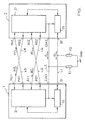
- the invention is described below with reference to the figure.
- the figure shows as an exemplary embodiment a data transmission system for serial transmission digital data between two stations.
- the stations 1, 2 have, for example around two microprocessors of a multiprocessor system - one shift register each 10 or 20 and in each case a control unit 11 or 21 for controlling the respective Shift registers 10 and 20 respectively. They also each have a data connection D1 or D2 for transmitting a data signal corresponding to the data d, in each case one clock connection CLK1 or CLK2 for transmitting a clock signal c, each a mode output MO1 or MO2 for delivering an operating mode of the respective station 1 or 2 corresponding mode signals m1 or m2, respectively a confirmation output AO1 or AO2 for emitting a confirmation signal a1 or a2 and a mode input MI1 or MI2 and a confirmation input AI1 or AI2.
- the data connections D1, D2 are connected to one another via a data line L1, the clock connections CLK1, CLK2 are connected to one another via a clock line L2, the mode output MO1 of the first station 1 is connected via a first signal line L3 to the mode input MI2 of the second station 2, which Mode output MO2 of the second station 2 is connected to the mode input MI1 of the first station 1 via a second signal line L4, the confirmation output AO1 of the first station 1 is connected to the confirmation input of the second station 2 via a third signal line L5 and the confirmation output AO2 of the second station 2 is connected via a fourth signal line L6 to the confirmation input AI1 of the first station.
- the data line L1 and the clock line L2 are for realizing a wired-or "connection in each case connected to a ground connection GND via a resistor R1 or R2.
- both stations 1, 2 When switching on the data transmission system and during transmission breaks, in where no data is exchanged, both stations 1, 2 are located in the Slave operating mode; it is a standby mode in which the stations 1, 2 do not emit a clock signal and in which they are ready to receive data are.
- the first station 1 first checks whether the second station 2 in the Slave operating mode is operated by the of the second station 2 on Mode output MO2 evaluates mode signal m2.
- the first station 1 is as soon as it detects that the second station 2 is operating in the slave operating mode is switched from the slave operating mode to the master operating mode; if necessary, the switchover is waited until the second station 2 leaves the Master operating mode is switched to the slave operating mode.
- With switching the operating mode of the first station 1 will also be that of the first station 1 inverted at its mode output MO1 mode signal m1, with what the second station 2 is displayed that the first station 1 is now in control has taken over the data transmission and the necessary clock signal c will generate.
- the first station 1 still detects the state, i. H. the logical Signal level, which is output by the second station 2 at its confirmation output AO2 Confirmation signal a2 and can then with the transmission of Dates begin.
- first n data bits for example 8 bits, are stored in the shift register 10 of the first station 1 is written and from there as a data signal d transferred to the shift register 20 of the second station 2.
- the transfer the data bits are synchronized with the clock signal c, which is sent by the control unit 11 of the first station 1 is generated and the clock line L2 Shift register 20 of the second station 2 is supplied.
- the reception of the last of the n data bits triggers a receive interrupt in the second station 2 , whereupon the data bits are read out from the shift register 20 and the state of the confirmation signal a2 to indicate that the data received, is inverted.
- the transmission of the last of the n data bits triggers in the first station 1 a send interrupt.
- the first station 1 the state of the confirmation signal a2 and writes as soon as Confirmation signal a2 a change in state was detected, the next n data bits into the shift register 10.
- the first station 1 After all data has been transferred, the first station 1 returns to the slave operating mode switched and this the second station 2 by inverting the am Mode output MO1 displayed mode signal m1 displayed. Both stations are now in slave mode and can, if necessary, Initiate transmission of further data.
- the exemplary embodiment described can also be applied to a data transmission system expand with more than 2 stations.
- the stations point for each additional station has an additional mode input for the mode signal of the additional station and an additional confirmation input for the confirmation signal the additional station.
- the data signal d and the clock signal c in such a data transmission system from one of the stations transmitted to all other stations simultaneously.
Landscapes
- Engineering & Computer Science (AREA)
- Computer Networks & Wireless Communication (AREA)
- Signal Processing (AREA)
- Small-Scale Networks (AREA)
- Information Transfer Systems (AREA)
Abstract
Description

Claims (9)
- Verfahren zur Übertragung digitaler Daten zwischen mindestens zwei Stationen (1, 2), dadurch gekennzeichnet,daß jede Station (1, 2) in einen die Datenübertragung steuernden Master-Betriebsmodus und in einen zum Empfang von Daten bereiten Slave-Betriebsmodus schaltbar ist,daß jede Station (1, 2) ihren Betriebsmodus durch ein Modussignal (m1, m2) anzeigt,daß jede Station (1, 2) zum Aussenden von Daten in den Master-Betriebsmodus geschaltet wird, wobei die Einschaltung des Master-Betriebsmodus erst dann erfolgt, wenn die Station anhand des Modussignals (m1, m2) jeder anderen Station erkennt, daß keine andere Station im Master-Betriebsmodus betrieben wird unddaß und jede Station (1, 2) nur solange im Master-Betriebsmodus geschaltet verbleibt, solange sie Daten aussendet.
- Verfahren nach Anspruch 1, dadurch gekennzeichnet, daß jede Station (1, 2) im Master-Betriebsmodus ein Taktsignal (c) zur Synchronisation der Datenübertragung generiert und Daten seriell in zum Taktsignal (c) synchronen Bitzellen aussendet, und daß jede Station (1, 2) im Slave-Betriebsmodus die zu ihr gesendeten Daten nach Maßgabe des Taktsignals (c) übernimmt.
- Verfahren nach Anspruch 2, dadurch gekennzeichnet, daß die im Master-Betriebsmodus betriebene Station (1, 2) eine vorgegebene Anzahl von Datenbits aussendet und mit dem Aussenden weiterer Datenbits wartet, bis der Empfang der ausgesendeten Datenbits von jeder anderen Station bestätigt wird.
- Verfahren nach Anspruch 3, dadurch gekennzeichnet, daß jede im Slave-Betriebsmodus betriebene Station (1, 2) den Empfang der vorgegebenen Anzahl von Datenbits durch Invertierung eines an die im Master-Betriebsmodus betriebene Station ausgesendeten Bestätigungssignals (a1, a2) bestätigt.
- Datenübertragungssystem zur Durchführung des Verfahrens nach einem der Ansprüche 2 bis 4, dadurch gekennzeichnet, daß jede Station (1, 2) einen Datenanschluß (D1, D2) für ein den Daten entsprechendes Datensignal (d), einen Taktanschluß (CLK1, CLK2) für das Taktsignal (c), einen Modusausgang (MO1, MO2) für ihr Modussignal (m1, m2), sowie für jede übrige Station (1, 2) einen dieser zugeordneten Moduseingang (MI1, MI2) aufweist, wobei die Datenanschlüsse (D1, D2) der Stationen (1, 2) miteinander verbunden sind, die Taktanschlüsse (CLK1, CLK2) der Stationen (1, 2) miteinander verbunden sind und der Modusausgang (MO1, MO2) jeder Station (1, 2) mit den zugeordneten Moduseingängen (MI1, MI2) der übrigen Stationen (1, 2) verbunden ist.
- Datenübertragungssystem nach Anspruch 5, dadurch gekennzeichnet, daß jede Station (1, 2) einen Bestätigungsausgang (AO1, AO2) für ihr Bestätigungssignal (a1, a2), sowie für jede übrige Station (1, 2) einen dieser zugeordneten Bestätigungseingang (AI1, AI2) aufweist, wobei der Bestätigungsausgang (AO1, AO2) jeder Station (1, 2) mit den zugeordneten Bestätigungseingängen (AI1, AI2) der übrigen Stationen (1, 2) verbunden ist.
- Datenübertragungssystem nach Anspruch 5 oder 6, dadurch gekennzeichnet, daß die Taktanschlüsse (CLK1, CLK2) über einen Widerstand (R1) mit einem Spannungsversorgungsanschluß (GND) verbunden sind.
- Datenübertragungssystem nach einem der Ansprüche 5 bis 7, dadurch gekennzeichnet, daß die Datenanschlüsse (D1, D2) über einen Widerstand (R2) mit einem Spannungsversorgungsanschluß (GND) verbunden sind.
- Datenübertragungssystem nach Anspruch 7 oder 8, dadurch gekennzeichnet, daß der Spannungsversorgungsanschluß (GND) ein Masseanschluß ist.
Applications Claiming Priority (2)
| Application Number | Priority Date | Filing Date | Title |
|---|---|---|---|
| DE1999123327 DE19923327C2 (de) | 1999-05-21 | 1999-05-21 | Verfahren zur seriellen Übertragung digitaler Daten |
| DE19923327 | 1999-05-21 |
Publications (2)
| Publication Number | Publication Date |
|---|---|
| EP1054531A2 true EP1054531A2 (de) | 2000-11-22 |
| EP1054531A3 EP1054531A3 (de) | 2004-01-21 |
Family
ID=7908734
Family Applications (1)
| Application Number | Title | Priority Date | Filing Date |
|---|---|---|---|
| EP00109837A Withdrawn EP1054531A3 (de) | 1999-05-21 | 2000-05-10 | Verfahren zur seriellen Übertragung digitaler Daten |
Country Status (2)
| Country | Link |
|---|---|
| EP (1) | EP1054531A3 (de) |
| DE (1) | DE19923327C2 (de) |
Families Citing this family (1)
| Publication number | Priority date | Publication date | Assignee | Title |
|---|---|---|---|---|
| DE10110673A1 (de) * | 2001-03-06 | 2002-09-26 | Siemens Ag | Röntgendetektorarray und Verfahren zu seiner Herstellung |
Family Cites Families (1)
| Publication number | Priority date | Publication date | Assignee | Title |
|---|---|---|---|---|
| US5313591A (en) * | 1992-06-25 | 1994-05-17 | Hewlett-Packard Company | Computer bus arbitration for N processors requiring only N unidirectional signal leads |
-
1999
- 1999-05-21 DE DE1999123327 patent/DE19923327C2/de not_active Expired - Lifetime
-
2000
- 2000-05-10 EP EP00109837A patent/EP1054531A3/de not_active Withdrawn
Also Published As
| Publication number | Publication date |
|---|---|
| DE19923327A1 (de) | 2000-11-30 |
| DE19923327C2 (de) | 2001-08-09 |
| EP1054531A3 (de) | 2004-01-21 |
Similar Documents
| Publication | Publication Date | Title |
|---|---|---|
| DE68925889T2 (de) | Kontrollvorrichtung in reihe | |
| EP0580016B1 (de) | Lokales Operationsnetzwerk | |
| DE2654050C3 (de) | Taktsignalsteuersystem eines Mikrocomputersystems | |
| DE3424866C2 (de) | Verfahren und Anordnung zur Übertragung von Daten, insbesondere in einem Flugzeug | |
| DE3004827C2 (de) | Datenverarbeitungsanlage | |
| DE4307449C2 (de) | Verfahren und Schaltung zur Resynchronisation einer synchronen seriellen Schnittstelle | |
| EP1370956B1 (de) | Bussystem aus wenigstens zwei datenbussen | |
| EP1657608B1 (de) | Verfahren und Vorrichtung zum Betreiben eines Netzwerkes | |
| DE3688732T2 (de) | Satellitenkommunikationssystem mit wahlfreiem Vielfachzugriff und Zeitschlitzreservierung. | |
| DE3300263A1 (de) | Schaltungsanordnung zur zuteilung des zugriffs zu einer auf anforderungsbasis gemeinsam benutzten sammelleitung | |
| DE1933577A1 (de) | System zum UEbertragen von Daten zwischen einem Rechner und mehreren entfernt liegenden Anschlussgeraeten | |
| DE19541637A1 (de) | Multiplex-Kommunikationssystem | |
| EP1841285B1 (de) | Hörgerätesystem mit binauralem DataLogging und entsprechendes Verfahren | |
| EP0114268A2 (de) | Schaltkreis-Baustein | |
| EP0863639A1 (de) | System zum Übertragen von Daten | |
| EP0920154A2 (de) | Verfahren und Schaltungsanordnung zur selektiven digitalen seriellen Übertragung | |
| EP1622039B1 (de) | Verfahren und Vorrichtung zur Adressvergabe an Teilnehmer eines Bussystems | |
| EP0175095B1 (de) | Datenübertragungsverfahren über einen Multiprozessorbus | |
| EP0509114A1 (de) | Verfahren zum Übertragen von Daten an mehrere Datenstationen | |
| DE19923327C2 (de) | Verfahren zur seriellen Übertragung digitaler Daten | |
| DE19536518C2 (de) | Verfahren zur Aufrechterhaltung des mikrosynchronen Betriebs von gedoppelten informationsverarbeitenden Einheiten | |
| DE69032078T2 (de) | Elektronische Anordnung mit Datenübertragungsfunktion | |
| EP1368738B1 (de) | Bussystem mit im multiplexbetrieb betreibbaren adress/datenbus und steuerbus zum ansprechen einer station durch zuweisung eines logischen kanals | |
| WO1997022057A1 (de) | Verfahren zur adresseinstellung an bussystemen mit paralleler verdrahtung und vorrichtung zur durchführung des verfahrens | |
| EP2097999A1 (de) | Verfahren zur handhabe von daten |
Legal Events
| Date | Code | Title | Description |
|---|---|---|---|
| PUAI | Public reference made under article 153(3) epc to a published international application that has entered the european phase |
Free format text: ORIGINAL CODE: 0009012 |
|
| AK | Designated contracting states |
Kind code of ref document: A2 Designated state(s): AT BE CH CY DE DK ES FI FR GB GR IE IT LI LU MC NL PT SE |
|
| AX | Request for extension of the european patent |
Free format text: AL;LT;LV;MK;RO;SI |
|
| RAP1 | Party data changed (applicant data changed or rights of an application transferred) |
Owner name: CONTI TEMIC MICROELECTRONIC GMBH |
|
| PUAL | Search report despatched |
Free format text: ORIGINAL CODE: 0009013 |
|
| RIC1 | Information provided on ipc code assigned before grant |
Ipc: 7G 06F 13/368 B Ipc: 7G 06F 13/42 A |
|
| AK | Designated contracting states |
Kind code of ref document: A3 Designated state(s): AT BE CH CY DE DK ES FI FR GB GR IE IT LI LU MC NL PT SE |
|
| AX | Request for extension of the european patent |
Extension state: AL LT LV MK RO SI |
|
| AKX | Designation fees paid | ||
| REG | Reference to a national code |
Ref country code: DE Ref legal event code: 8566 |
|
| STAA | Information on the status of an ep patent application or granted ep patent |
Free format text: STATUS: THE APPLICATION IS DEEMED TO BE WITHDRAWN |
|
| 18D | Application deemed to be withdrawn |
Effective date: 20040722 |