EP1054284A1 - Dispositif de visualisation par caméra numérique miniature - Google Patents
Dispositif de visualisation par caméra numérique miniature Download PDFInfo
- Publication number
- EP1054284A1 EP1054284A1 EP00401385A EP00401385A EP1054284A1 EP 1054284 A1 EP1054284 A1 EP 1054284A1 EP 00401385 A EP00401385 A EP 00401385A EP 00401385 A EP00401385 A EP 00401385A EP 1054284 A1 EP1054284 A1 EP 1054284A1
- Authority
- EP
- European Patent Office
- Prior art keywords
- torch
- image sensor
- head
- camera
- display device
- Prior art date
- Legal status (The legal status is an assumption and is not a legal conclusion. Google has not performed a legal analysis and makes no representation as to the accuracy of the status listed.)
- Granted
Links
- 238000012545 processing Methods 0.000 claims abstract description 18
- 230000009975 flexible effect Effects 0.000 claims abstract description 10
- 239000013307 optical fiber Substances 0.000 claims description 8
- 239000004033 plastic Substances 0.000 claims description 7
- 229920003023 plastic Polymers 0.000 claims description 7
- 230000008878 coupling Effects 0.000 claims description 5
- 238000010168 coupling process Methods 0.000 claims description 5
- 238000005859 coupling reaction Methods 0.000 claims description 5
- 238000010292 electrical insulation Methods 0.000 claims description 4
- 239000002184 metal Substances 0.000 claims description 4
- 229910052751 metal Inorganic materials 0.000 claims description 4
- 229920000642 polymer Polymers 0.000 claims description 4
- 229910052736 halogen Inorganic materials 0.000 claims description 3
- 150000002367 halogens Chemical class 0.000 claims description 3
- 229920003229 poly(methyl methacrylate) Polymers 0.000 claims description 3
- 239000004926 polymethyl methacrylate Substances 0.000 claims description 3
- 239000011347 resin Substances 0.000 claims description 3
- 229920005989 resin Polymers 0.000 claims description 3
- 238000003466 welding Methods 0.000 claims description 3
- 229920000271 Kevlar® Polymers 0.000 claims description 2
- 239000011521 glass Substances 0.000 claims description 2
- 239000004761 kevlar Substances 0.000 claims description 2
- 239000012811 non-conductive material Substances 0.000 claims description 2
- 230000003647 oxidation Effects 0.000 claims description 2
- 238000007254 oxidation reaction Methods 0.000 claims description 2
- 229920003223 poly(pyromellitimide-1,4-diphenyl ether) Polymers 0.000 claims description 2
- 229910052710 silicon Inorganic materials 0.000 claims description 2
- 239000010703 silicon Substances 0.000 claims description 2
- 125000002496 methyl group Chemical group [H]C([H])([H])* 0.000 claims 1
- 229920000193 polymethacrylate Polymers 0.000 claims 1
- 235000010599 Verbascum thapsus Nutrition 0.000 description 32
- 244000178289 Verbascum thapsus Species 0.000 description 6
- 238000012800 visualization Methods 0.000 description 4
- 230000008901 benefit Effects 0.000 description 3
- 230000015556 catabolic process Effects 0.000 description 3
- 238000010586 diagram Methods 0.000 description 3
- 238000005516 engineering process Methods 0.000 description 3
- 210000000056 organ Anatomy 0.000 description 3
- ATJFFYVFTNAWJD-UHFFFAOYSA-N Tin Chemical compound [Sn] ATJFFYVFTNAWJD-UHFFFAOYSA-N 0.000 description 2
- 239000003990 capacitor Substances 0.000 description 2
- 230000007797 corrosion Effects 0.000 description 2
- 238000005260 corrosion Methods 0.000 description 2
- 238000003745 diagnosis Methods 0.000 description 2
- 239000000835 fiber Substances 0.000 description 2
- 238000007689 inspection Methods 0.000 description 2
- 238000012423 maintenance Methods 0.000 description 2
- 238000013024 troubleshooting Methods 0.000 description 2
- 238000009423 ventilation Methods 0.000 description 2
- 208000031968 Cadaver Diseases 0.000 description 1
- 244000245420 ail Species 0.000 description 1
- 230000000295 complement effect Effects 0.000 description 1
- 238000001816 cooling Methods 0.000 description 1
- 238000012937 correction Methods 0.000 description 1
- 239000013078 crystal Substances 0.000 description 1
- 238000013461 design Methods 0.000 description 1
- 238000001514 detection method Methods 0.000 description 1
- 238000009792 diffusion process Methods 0.000 description 1
- 230000005611 electricity Effects 0.000 description 1
- 239000012530 fluid Substances 0.000 description 1
- PCHJSUWPFVWCPO-UHFFFAOYSA-N gold Chemical compound [Au] PCHJSUWPFVWCPO-UHFFFAOYSA-N 0.000 description 1
- 239000010931 gold Substances 0.000 description 1
- 229910052737 gold Inorganic materials 0.000 description 1
- 238000002329 infrared spectrum Methods 0.000 description 1
- 239000007788 liquid Substances 0.000 description 1
- 239000004973 liquid crystal related substance Substances 0.000 description 1
- 238000004519 manufacturing process Methods 0.000 description 1
- 229910044991 metal oxide Inorganic materials 0.000 description 1
- 150000004706 metal oxides Chemical class 0.000 description 1
- 239000010705 motor oil Substances 0.000 description 1
- 239000003921 oil Substances 0.000 description 1
- 238000004171 remote diagnosis Methods 0.000 description 1
- 239000004065 semiconductor Substances 0.000 description 1
- 229910000679 solder Inorganic materials 0.000 description 1
- 238000012546 transfer Methods 0.000 description 1
- 238000001429 visible spectrum Methods 0.000 description 1
Images



Classifications
-
- G—PHYSICS
- G02—OPTICS
- G02B—OPTICAL ELEMENTS, SYSTEMS OR APPARATUS
- G02B23/00—Telescopes, e.g. binoculars; Periscopes; Instruments for viewing the inside of hollow bodies; Viewfinders; Optical aiming or sighting devices
- G02B23/24—Instruments or systems for viewing the inside of hollow bodies, e.g. fibrescopes
- G02B23/2407—Optical details
- G02B23/2461—Illumination
- G02B23/2469—Illumination using optical fibres
-
- G—PHYSICS
- G02—OPTICS
- G02B—OPTICAL ELEMENTS, SYSTEMS OR APPARATUS
- G02B23/00—Telescopes, e.g. binoculars; Periscopes; Instruments for viewing the inside of hollow bodies; Viewfinders; Optical aiming or sighting devices
- G02B23/24—Instruments or systems for viewing the inside of hollow bodies, e.g. fibrescopes
- G02B23/2476—Non-optical details, e.g. housings, mountings, supports
- G02B23/2484—Arrangements in relation to a camera or imaging device
-
- H—ELECTRICITY
- H04—ELECTRIC COMMUNICATION TECHNIQUE
- H04N—PICTORIAL COMMUNICATION, e.g. TELEVISION
- H04N23/00—Cameras or camera modules comprising electronic image sensors; Control thereof
- H04N23/50—Constructional details
- H04N23/555—Constructional details for picking-up images in sites, inaccessible due to their dimensions or hazardous conditions, e.g. endoscopes or borescopes
-
- H—ELECTRICITY
- H04—ELECTRIC COMMUNICATION TECHNIQUE
- H04N—PICTORIAL COMMUNICATION, e.g. TELEVISION
- H04N23/00—Cameras or camera modules comprising electronic image sensors; Control thereof
- H04N23/56—Cameras or camera modules comprising electronic image sensors; Control thereof provided with illuminating means
Definitions
- the present invention relates to a device for visualization by digital camera, with miniaturized head flexible and adjustable, endoscope type, for the inspection of the inaccessible areas of an organ, in particular of a motor vehicle engine.
- a solution to reduce the time of determination of a breakdown, therefore the intervention time not invoiced, consists in allowing the repairer to view the organ directly and immediately by failure, without dismantling the ancillary components.
- Gold currently there is no vision system direct by miniature camera in the field of automotive after-sales.
- CMOS Complementary Metal Oxide Semiconductor
- FIGS. 1 a and 1 b are respectively a front view and a schematic sectional view of a CCD or CMOS camera of the printed card type comprising, on a printed circuit 10, a CCD or CMOS image sensor 20 in front of which is placed a lens 30, an integrated circuit 40 and at least one resistor 50 and a capacitor 60.
- the control circuit in the integrated circuit is near the sensor. If the CCD sensor is removed from its large processing electronics, it remains necessary to have printed control circuits near the sensor, which increases the cost of the display device.
- the dimensions of the printed card 10, of width D 1 are often large and determine the final diameter of the torch head.
- Lighting can be obtained, as is described in the aforementioned patent application, by diodes or remote lamps at the CCD sensor or CMOS. To solve dissipation problems thermal, thermal bridges are planned.
- a solution to the problem of the final diameter of the video torch would be to move the sensor away from its electronic processing circuit, as is described in US Patent 5,233,426 to Matsushita Electric, but in this case, several problems arise would also pose, in particular the clock phase of CCD sensor control and voltage drop at the CCD sensor.
- the driving circuits are placed behind CCD sensor with printed circuits additional, while miniature connectors are placed at the endoscope head. This solution is complex to realize, increases the thickness of the endoscope head so its bulk and is expensive.
- the object of the invention is to overcome these different disadvantages by proposing a device for endoscope type, with a small digital camera size, including the total cost of the tool and its after-sales maintenance is reduced.
- the compensation of clock phases of the image sensor is provided by passive components, such as capacity or inductance, connected by welding to the legs connection of the image sensor.
- the means of lighting the scene to be displayed are constituted by a lamp, incandescent or halogen, single, or by a light emitting diode, placed in the handle of the torch, and associated with means light guide formed by a beam of optical fibers, plastic for example.
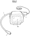
- the display device direct by miniature digital camera, type endoscope, consists on the one hand of a camera CCD or CMOS or CMOS-APS digital type (Active Pixel Sensor), implanted in a torch 1 and other part of a display screen 100 of images produced by the camera which is crystal type liquids for example, as shown in Figure 2, or with cathode ray tube. It is characterized by the offset of the single CCD or CMOS image sensor in head 2 of torch, while its processing electronics are located in handle 4, the clock phases in front be compensated in particular by passive components, of the capacitor or self type, made either in the surface mount component technology in discrete component technology.
- CMOS or CMOS-APS digital type Active Pixel Sensor
- the proposed solution to the size problem minimum of the head 2 of the video torch 1 consists, at the digital camera level, separate circuit 3 CCD or CMOS image sensor of the printed circuit 5 which includes the electronic control circuit and the video signal processing electronic circuit, as shown in Figure 3 which is a sectional diagram longitudinal view of a digital camera according to a first embodiment of the display device.
- the digital image sensor 3 and its lens 6 are housed in head 2 while the electronics of treatment is housed in the handle 4 of the device.
- the outside diameter D 2 of the head 2 is slightly greater than that of the image sensor, but is much less the dimensions, in particular the width D 1 of the printed card 5.
- the objective whether or not controlled, has the function of forming images of the scene to be observed on the sensitive surface of the CCD sensor. It can be of the pin hole or simple lens type with a very small numerical aperture to benefit from the great depth of field.
- connection tabs 7 of the sensor circuit 3 images are no longer directly welded to the printed circuit 5, but each is soldered with tin to a first end 8 of an electric wire 10, of which the second end 9 is connected to the printed circuit of the video signal processing electronics, placed in handle 4 of the torch. Tin solders are referenced 11.
- These electrical wires 10 must have a low linear resistivity and their maximum length 1 between the head 2 and the handle 4 of the device must be less than 30 cm for color sensors, or 60 cm for black and white sensors, which is quite sufficient for a torch application endoscope type video.
- passive components 12, of the capacity or inductance type are also connected by welding to the legs 7 of connection of the image sensor 3.
- its legs connection are molded in an insulating resin 13, except on its sensitive face 14 made of silicon, which is sealed under a rare gas by a layer of glass 15 avoiding its oxidation, and on the lens.
- the passive components 12, of the capacity or inductance type are connected on a flex-rigid support 16, on which is previously soldered to the sensor 3 circuit image.
- This flex-rigid support 16 can be connected to a bundle 17 of electric wires embedded in a ribbon Kevlar or Kapton, replacing a strand of wire electric 10.
- Such an embodiment is particularly suitable good at producing a large number of video endoscopes at low cost.
- a second embodiment of a camera numerical represented diagrammatically in FIG. 5, one can arrange the passive components of correction of clock phases on the printed board 5 housed in the handle 4 of the vision device.
- This solution is also possible because the maximum offset distance between image sensor 3 and the circuits control and processing electronics placed on printed circuit board 5, so the length of the cables, i.e. sheathed connecting electrical wires 10 is close to 30 cm for a color sensor and 60 cm for a black and white sensor.
- capacitances C and inductors L for compensation of clock control signals, for acquisition and playback of the video signal.
- the strand of signal connecting cables 10 clock is electromagnetically shielded by a metal sheath 18, in the form of a braid for example, connected to electrical ground and / or mechanical ground the printed circuit 5 and the image sensor 3.
- FIG. 6 is a complete diagram in section longitudinal of the torch of a device display according to the invention, composed of a head 2 rigid connected to a handle 4 by a flexible tube 19, of diameter smaller than that of the hollow body of the head.
- the flexible tube 19 is made of plastic for avoid any problem of electric short circuit during troubleshooting by the tool diagnosis
- the handle 4 consists of a tube rigid metal to facilitate handling of the torch and plasticized for its electrical insulation.
- the torch head, in which the sensor is housed image 3 is made from a hollow body metallic, generally cylindrical or frustoconical, rigid to protect the image sensor but covered with a non-conductive material, such as plastic, for its electrical insulation.
- the proposed solution for stage lighting to be observed by means of the head of the visualization, without increasing the volume of the head the torch, consists of housing the lighting means in handle 4, not in head 2.
- These means are for example a lamp 23, ncandescente or halogen, unique, placed in the handle 4, associated with light guiding means. This may also be a light emitting diode.
- the lamp must be of cost and consumption electric weak.
- the advantage of putting it in the torch handle lies in the ease of replacement in case of failure, in services automotive after-sales service that can provide maintenance of the video device.
- the light emitted by this lamp 23 is guided by a bundle of optical fibers 20, made of plastic by example, towards the head 2 of the torch.
- the lamp 23 is placed at the entry of the optical fibers of the bundle, the coupling in the air sufficient to transport the light via the fibers towards the head. This air coupling is simple and the lamp change, when it is grilled, is very easy, which would not be the case with resin coupling.
- each of the optical fibers is pressed against a ring 21 of diffusing polymer, PMMA - Poly Methyl Methacrylate - no transparent, which provides lighting diffuse Lambertian type in the field of vision of the digital camera.
- a ring 21 of diffusing polymer PMMA - Poly Methyl Methacrylate - no transparent, which provides lighting diffuse Lambertian type in the field of vision of the digital camera.
- optical fibers of two are diametrically opposite, otherwise they are distributed symmetrically with respect to the center, i.e. at 90 ° if there are four for example, as shown in the figure 2.
- objective 6 of the image sensor 3 of the pin hole type or simple lens with low numerical aperture.
- a circular plate 22, in transparent polymer is glued to the end of head 2 of the torch to ensure total tightness of this diagnostic tool thus realized.
- the wavelength range used for the CCD, or CMOS sensor, and the lighting means can be in the visible or infrared spectrum or ultraviolet.
- the power source is battery type, rechargeable battery or accumulator, located in the handle 4 or in the screen box display 100.
- the video device is powered from a bay remote diagnosis, via the electricity network in 110 or 220 Volts.
- the means of starting the torch of the device are placed on the handle 4, as well as lighting means necessary for the image sensor.
- Such a display device according to the invention will advantageously be used as a tool for diagnosis of breakdowns in motor vehicles, especially at the engine.
- This tool allows decrease the fault finding time, i.e. disassembly and reassembly not billed to the customer.
- this endoscope diagnostic tool video has a very low cost, allowing great diffusion not only in the automotive sector, but still in aeronautics or in the industrial machinery.
Landscapes
- Physics & Mathematics (AREA)
- Engineering & Computer Science (AREA)
- Multimedia (AREA)
- Astronomy & Astrophysics (AREA)
- General Physics & Mathematics (AREA)
- Optics & Photonics (AREA)
- Signal Processing (AREA)
- Studio Devices (AREA)
- Endoscopes (AREA)
- Instruments For Viewing The Inside Of Hollow Bodies (AREA)
- Closed-Circuit Television Systems (AREA)
Abstract
- dans le corps creux de la tête (2) est logé le capteur d'images (3) de la caméra ;
- dans le manche (4) sont déportés les moyens de traitement électronique et de pilotage d'horloge de la caméra, ainsi que l'éclairage de la scène à visualiser;
- dans le tube flexible (19) reliant la tête (2) à son
manche (4) sont protégés les câbles électriques (10) de
liaison entre le capteur et ses moyens de traitement,
ainsi que des moyens de guidage de la lumière émise
vers la tête de la torche,
et qu'une compensation des phases d'horloge du capteur (3) est prévue aux extrémités des fils (10) de liaison, entre le capteur et ses moyens de traitement.
Description
- le capteur d'image CCD ou CMOS proprement dit ;
- le circuit électronique de pilotage des phases d'horloge nécessaires au fonctionnement de ce capteur ;
- le circuit électronique de traitement du signal vidéo.
- dans le corps creux de la tête de la torche est logé le capteur d'images de la caméra ;
- dans le manche non conducteur de la torche sont déportés d'une part les moyens de traitement électronique et de pilotage d'horloge de la caméra numérique, et d'autre part les moyens d'éclairage de la scène à visualiser ;
- dans le tube flexible non conducteur, reliant la tête de la torche à son manche, sont protégés les câbles électriques blindés de liaison entre le capteur d'images et ses moyens de traitement, ainsi que des moyens de guidage de la lumière émise par des moyens d'éclairage vers la tête de la torche,
- la figure 2 : une vue complète d'un dispositif de visualisation avec écran selon l'invention ;
- les figures 3 et 4 : deux variantes de réalisation d'une caméra de torche vidéo, en coupe schématique longitudinale selon le premier mode de réalisation de l'invention ;
- la figure 5 : un schéma d'une caméra d'une tête de torche vidéo, selon un deuxième mode de réalisation de l'invention ;
- la figure 6 : une vue en coupe longitudinale d'un dispositif de visualisation selon l'invention.
- lecture directe des références de pièces non accessibles à l'oeil du garagiste ;
- recherche de fuite de liquide de frein, d'huile de la boíte de vitesse, d'huile du moteur ou du circuit de refroidissement ;
- recherche de points de corrosion dans les ailes de la carrosserie ou au niveau du passage de roues ;
- recherche de défaut d'étanchéité ;
- recherche de chemin de câbles électriques dans le tableau de bord ;
- recherche de pannes électriques dans les circuits de ventilation.
Claims (13)
- Dispositif de visualisation par caméra numérique, de type endoscope, constitué d'une part d'une caméra numérique miniature à circuit imprimé, implantée dans une torche et d'autre part d'un écran de visualisation des images produites par la caméra, caractérisé en ce que :et en ce que des moyens de compensation des phases d'horloge du capteur d'image (3) déporté sont ajoutés aux extrémités des fils électriques (10) de liaison, entre le capteur et ses moyens de traitement.dans le corps creux de la tête (2) de la torche (1) est logé le capteur d'images (3) de la caméra ;dans le manche (4) non conducteur de la torche sont déportés d'une part les moyens de traitement électronique et de pilotage d'horloge de la caméra numérique, et d'autre part les moyens d'éclairage de la scène à visualiser ;dans le tube flexible (19) non conducteur reliant la tête (2) de la torche à son manche (4) sont protégés les câbles électriques (10) blindés de liaison entre le capteur d'images et ses moyens de traitement, ainsi que des moyens de guidage de la lumière émise par des moyens d'éclairage vers la tête de la torche,
- Dispositif de visualisation selon la revendication 1, caractérisé en ce que chacune des pattes (7) de connexion du circuit capteur d'images (3), logé dans la tête (2) de la torche, est directement soudée à une première extrémité (8) d'un câble électrique (10) de liaison, dont la seconde extrémité (9) est connectée au circuit imprimé (5) de l'électronique de traitement du signal vidéo, placé dans le manche (4) de la torche.
- Dispositif de visualisation selon la revendication 1, caractérisé en ce que la compensation des phases d'horloge du capteur d'image (3) est assurée par des composants passifs (12), de type capacité ou inductance, reliés par soudure aux pattes (7) de connexion du capteur d'images (3).
- Dispositif de visualisation selon la revendication 3, caractérisé en ce que, pour assurer la rigidité de l'ensemble des connexions entre les pattes du capteur d'image (3) et d'une part les fils de liaison (10), et d'autre part les composants passifs (12), les pattes de connexion sont moulées dans une résine (13) isolante, excepté sur sa face sensible (14) en silicium, qui est scellée sous un gaz rare par une couche de verre (15) évitant son oxydation, et sur l'objectif.
- Dispositif de visualisation selon la revendication 3, caractérisé en ce que les composants passifs (12) de compensation, de type capacité ou inductance, sont connectés sur un support flex-rigide (16), sur lequel est soudé préalablement le circuit (3) capteur d'image et qui est connecté à un faisceau (17) de fils électriques noyés dans un ruban de Kevlar ou Kapton et connectés au circuit imprimé (5) de la caméra dans le manche (4) de la torche.
- Dispositif de visualisation selon la revendication 1, caractérisé en ce que la compensation des phases d'horloge du capteur d'image (3) est assurée par des composants passifs (12), de type capacité ou inductance, connectés sur la carte imprimée (5) de la caméra logée dans le manche (4) du dispositif de vision.
- Dispositif de visualisation selon la revendication 2, caractérisé en ce que les câbles électriques de liaison (10) sont des câbles simples multibrins, à très faible résistivité linéaire, de l'ordre de 0,002 Ohm par mètre, pour éviter les chutes de tension d'alimentation au niveau du capteur d'image (3) de la caméra.
- Dispositif de visualisation selon la revendication 7, caractérisé en ce que le toron de câbles (10) de liaison des signaux d'horloge est blindé électromagnétiquement par une gaine métallique (18), en forme de tresse par exemple, reliée à la masse électrique et/ou à la masse mécanique du circuit imprimé (5) et du capteur d'images (3).
- Dispositif de visualisation selon la revendication 1, caractérisé en ce que les moyens d'éclairage sont constitués par une lampe (23), incandescente ou halogène, unique, ou par une diode électroluminescente, placée dans le manche (4) de la torche, et associée à des moyens de guidage de la lumière.
- Dispositif de visualisation selon la revendication 9, caractérisé en ce que les moyens de guidage de la lumière, émise par la lampe (23) vers la tête (2) de la torche, sont constitués par un faisceau d'au moins deux fibres optiques (20), en plastique par exemple, la lampe (19) étant placée à l'entrée des fibres optiques du faisceau, auquel elle est couplée par un couplage dans l'air.
- Dispositif de visualisation selon la revendication 10, caractérisé en ce que les extrémités respectives de chacune des fibres optiques, opposée à la lampe (23), sont plaquées contre un anneau (21) en polymère diffusant, du type PMMA - Poly-Méthacrylate de Méthyle - non transparent, destiné à fournir un éclairage diffus de type Lambertien dans le champ de vision de la caméra numérique, symétriquement par rapport au centre percé de l'anneau, dans lequel est placé l'objectif (6) du capteur d'images (3), et en ce qu'une plaque (22) circulaire, en polymère transparent, est collée sur l'extrémité de la tête (2) de la torche.
- Dispositif de visualisation selon la revendication 1, caractérisé en ce que :la tête (2) de la torche, dans laquelle est logé le capteur d'image (3), est réalisée à partir d'un corps creux métallique rigide pour protéger le capteur d'images, et recouvert d'un matériau non conducteur, tel que du plastique, pour son isolation électrique,le tube flexible (19) reliant ladite tête à un manche (4), est de diamètre inférieur à celui de la tête et réalisé en plastique pour éviter tout court-circuit électrique pendant la recherche de panne par l'outil de diagnostic, etle manche (4) est constitué d'un tube métallique rigide et plastifié pour son isolation électrique.
- Dispositif de visualisation selon l'une des revendications 1 à 12, caractérisé en ce que la caméra numérique miniature est de type CCD ou CMOS ou CMOS-APS.
Applications Claiming Priority (2)
| Application Number | Priority Date | Filing Date | Title |
|---|---|---|---|
| FR9906497 | 1999-05-21 | ||
| FR9906497A FR2793893B1 (fr) | 1999-05-21 | 1999-05-21 | Dispositif de visualisation par camera numerique miniature |
Publications (2)
| Publication Number | Publication Date |
|---|---|
| EP1054284A1 true EP1054284A1 (fr) | 2000-11-22 |
| EP1054284B1 EP1054284B1 (fr) | 2005-09-07 |
Family
ID=9545884
Family Applications (1)
| Application Number | Title | Priority Date | Filing Date |
|---|---|---|---|
| EP00401385A Expired - Lifetime EP1054284B1 (fr) | 1999-05-21 | 2000-05-19 | Dispositif de visualisation par caméra numérique miniature |
Country Status (3)
| Country | Link |
|---|---|
| EP (1) | EP1054284B1 (fr) |
| DE (1) | DE60022426T2 (fr) |
| FR (1) | FR2793893B1 (fr) |
Cited By (1)
| Publication number | Priority date | Publication date | Assignee | Title |
|---|---|---|---|---|
| WO2007015101A3 (fr) * | 2005-08-03 | 2007-06-07 | Super Rod Ltd | Outil d'inspection |
Citations (10)
| Publication number | Priority date | Publication date | Assignee | Title |
|---|---|---|---|---|
| US4491865A (en) * | 1982-09-29 | 1985-01-01 | Welch Allyn, Inc. | Image sensor assembly |
| US4905082A (en) * | 1987-05-06 | 1990-02-27 | Olympus Optical Co., Ltd. | Rigid video endoscope having a detachable imaging unit |
| EP0421893A2 (fr) * | 1989-10-05 | 1991-04-10 | Welch Allyn, Inc. | Endoscope portatif pour la formation d'images en couleur |
| US5233426A (en) * | 1990-12-28 | 1993-08-03 | Matsushita Electric Industrial Co., Ltd. | Reduced diameter camera head for solid-state image pickup device and method of producing same |
| EP0587514A1 (fr) * | 1992-09-11 | 1994-03-16 | Welch Allyn, Inc. | Module processeur pour sonde d'inspection à vidéo |
| WO1994023539A1 (fr) * | 1993-04-07 | 1994-10-13 | Optik, Inc. | Endoscope pourvu d'un dispositif a couplage de charge a son extremite distale |
| US5373317A (en) * | 1993-05-28 | 1994-12-13 | Welch Allyn, Inc. | Control and display section for borescope or endoscope |
| US5389968A (en) * | 1991-04-11 | 1995-02-14 | Yugengaisha Wai-Kei Kikaku | CCD television camera with separated camera head |
| US5588950A (en) * | 1994-07-11 | 1996-12-31 | Asahi Kogaku Kogyo Kabushiki Kaisha | Portable endoscope system |
| FR2737650A1 (fr) * | 1995-08-07 | 1997-02-14 | Tokendo Sarl | Videoendoscope |
Family Cites Families (1)
| Publication number | Priority date | Publication date | Assignee | Title |
|---|---|---|---|---|
| FR2775151B1 (fr) * | 1998-02-17 | 2000-04-07 | Renault | Dispositif de visualisation par camera a tete flexible |
-
1999
- 1999-05-21 FR FR9906497A patent/FR2793893B1/fr not_active Expired - Lifetime
-
2000
- 2000-05-19 EP EP00401385A patent/EP1054284B1/fr not_active Expired - Lifetime
- 2000-05-19 DE DE60022426T patent/DE60022426T2/de not_active Expired - Lifetime
Patent Citations (11)
| Publication number | Priority date | Publication date | Assignee | Title |
|---|---|---|---|---|
| US4491865A (en) * | 1982-09-29 | 1985-01-01 | Welch Allyn, Inc. | Image sensor assembly |
| US4905082A (en) * | 1987-05-06 | 1990-02-27 | Olympus Optical Co., Ltd. | Rigid video endoscope having a detachable imaging unit |
| EP0421893A2 (fr) * | 1989-10-05 | 1991-04-10 | Welch Allyn, Inc. | Endoscope portatif pour la formation d'images en couleur |
| US5233426A (en) * | 1990-12-28 | 1993-08-03 | Matsushita Electric Industrial Co., Ltd. | Reduced diameter camera head for solid-state image pickup device and method of producing same |
| US5389968A (en) * | 1991-04-11 | 1995-02-14 | Yugengaisha Wai-Kei Kikaku | CCD television camera with separated camera head |
| EP0587514A1 (fr) * | 1992-09-11 | 1994-03-16 | Welch Allyn, Inc. | Module processeur pour sonde d'inspection à vidéo |
| WO1994023539A1 (fr) * | 1993-04-07 | 1994-10-13 | Optik, Inc. | Endoscope pourvu d'un dispositif a couplage de charge a son extremite distale |
| US5373317A (en) * | 1993-05-28 | 1994-12-13 | Welch Allyn, Inc. | Control and display section for borescope or endoscope |
| US5373317B1 (en) * | 1993-05-28 | 2000-11-21 | Welch Allyn Inc | Control and display section for borescope or endoscope |
| US5588950A (en) * | 1994-07-11 | 1996-12-31 | Asahi Kogaku Kogyo Kabushiki Kaisha | Portable endoscope system |
| FR2737650A1 (fr) * | 1995-08-07 | 1997-02-14 | Tokendo Sarl | Videoendoscope |
Cited By (1)
| Publication number | Priority date | Publication date | Assignee | Title |
|---|---|---|---|---|
| WO2007015101A3 (fr) * | 2005-08-03 | 2007-06-07 | Super Rod Ltd | Outil d'inspection |
Also Published As
| Publication number | Publication date |
|---|---|
| FR2793893A1 (fr) | 2000-11-24 |
| EP1054284B1 (fr) | 2005-09-07 |
| DE60022426D1 (de) | 2005-10-13 |
| DE60022426T2 (de) | 2006-06-29 |
| FR2793893B1 (fr) | 2002-07-19 |
Similar Documents
| Publication | Publication Date | Title |
|---|---|---|
| EP0567385B1 (fr) | Dispositif d'acquisition d'images d'un objet | |
| FR2800983A1 (fr) | Endoscope equipe d'une camera video et dispositif de rotation de camera | |
| WO2013124184A1 (fr) | Dispositif endoscopique destiné notamment à un usage médical | |
| CN202330866U (zh) | 内窥镜装置 | |
| FR3086768A1 (fr) | Dispositif de protection d’un capteur optique d’un systeme d’assistance a la conduite pour vehicule automobile | |
| FR3023926A1 (fr) | Dispositif d'affichage, notamment pour vehicule automobile | |
| WO2011092903A1 (fr) | Unité de prise d'image pour endoscope | |
| FR3050542B1 (fr) | Afficheur comprenant un capteur de lumiere | |
| JP2012034947A (ja) | 電子内視鏡 | |
| EP1054284B1 (fr) | Dispositif de visualisation par caméra numérique miniature | |
| FR2904435A1 (fr) | Sonde endoscopique integrant un objectif ayant un encombrement reduit | |
| EP0628845A1 (fr) | Jumelle de vision nocturne à imagerie électronique | |
| EP0703481A1 (fr) | Episcope jour-nuit | |
| FR2783611A1 (fr) | Endoscope video | |
| JPH06130305A (ja) | 電子内視鏡 | |
| CA3206942A1 (fr) | Dispositif intensificateur d'image avec alimentation disposee en amont de la photocathode | |
| EP2867716B1 (fr) | Dispositif de surveillance de l'environnement extérieur d'une plate-forme notamment navale, périscope et plate-forme comportant un tel dispositif | |
| WO1999043151A1 (fr) | Dispositif de visualisation par camera a tete flexible | |
| EP0359634B1 (fr) | Episcope de conduite et d'observation jour et nuit pour véhicule blindé | |
| WO1999000983A1 (fr) | Dispositif video et systeme de transmission d'informations video et audio pour le telediagnostic | |
| EP3167328A1 (fr) | Dispositif d'affichage, notamment pour vehicule automobile | |
| FR2761561A1 (fr) | Sonde videoendoscopique a senseur ccd distal | |
| FR3107124A1 (fr) | Appareil pour l’observation d’un astre | |
| WO1991018309A1 (fr) | Systeme de connexion optique et son utilisation a la transmission de signaux video | |
| JP4864539B2 (ja) | 電子内視鏡 |
Legal Events
| Date | Code | Title | Description |
|---|---|---|---|
| PUAI | Public reference made under article 153(3) epc to a published international application that has entered the european phase |
Free format text: ORIGINAL CODE: 0009012 |
|
| AK | Designated contracting states |
Kind code of ref document: A1 Designated state(s): BE DE |
|
| AX | Request for extension of the european patent |
Free format text: AL;LT;LV;MK;RO;SI |
|
| 17P | Request for examination filed |
Effective date: 20010518 |
|
| AKX | Designation fees paid |
Free format text: BE DE |
|
| RAP1 | Party data changed (applicant data changed or rights of an application transferred) |
Owner name: RENAULT S.A.S. |
|
| 17Q | First examination report despatched |
Effective date: 20040408 |
|
| GRAP | Despatch of communication of intention to grant a patent |
Free format text: ORIGINAL CODE: EPIDOSNIGR1 |
|
| GRAS | Grant fee paid |
Free format text: ORIGINAL CODE: EPIDOSNIGR3 |
|
| GRAA | (expected) grant |
Free format text: ORIGINAL CODE: 0009210 |
|
| AK | Designated contracting states |
Kind code of ref document: B1 Designated state(s): BE DE |
|
| REF | Corresponds to: |
Ref document number: 60022426 Country of ref document: DE Date of ref document: 20051013 Kind code of ref document: P |
|
| PLBE | No opposition filed within time limit |
Free format text: ORIGINAL CODE: 0009261 |
|
| STAA | Information on the status of an ep patent application or granted ep patent |
Free format text: STATUS: NO OPPOSITION FILED WITHIN TIME LIMIT |
|
| 26N | No opposition filed |
Effective date: 20060608 |
|
| PGFP | Annual fee paid to national office [announced via postgrant information from national office to epo] |
Ref country code: DE Payment date: 20170523 Year of fee payment: 18 |
|
| PGFP | Annual fee paid to national office [announced via postgrant information from national office to epo] |
Ref country code: BE Payment date: 20170519 Year of fee payment: 18 |
|
| REG | Reference to a national code |
Ref country code: DE Ref legal event code: R119 Ref document number: 60022426 Country of ref document: DE |
|
| REG | Reference to a national code |
Ref country code: BE Ref legal event code: MM Effective date: 20180531 |
|
| PG25 | Lapsed in a contracting state [announced via postgrant information from national office to epo] |
Ref country code: DE Free format text: LAPSE BECAUSE OF NON-PAYMENT OF DUE FEES Effective date: 20181201 |
|
| PG25 | Lapsed in a contracting state [announced via postgrant information from national office to epo] |
Ref country code: BE Free format text: LAPSE BECAUSE OF NON-PAYMENT OF DUE FEES Effective date: 20180531 |