EP1053901A2 - Radiator for internal combustion engine - Google Patents
Radiator for internal combustion engine Download PDFInfo
- Publication number
- EP1053901A2 EP1053901A2 EP00106381A EP00106381A EP1053901A2 EP 1053901 A2 EP1053901 A2 EP 1053901A2 EP 00106381 A EP00106381 A EP 00106381A EP 00106381 A EP00106381 A EP 00106381A EP 1053901 A2 EP1053901 A2 EP 1053901A2
- Authority
- EP
- European Patent Office
- Prior art keywords
- cooler
- section
- outer contour
- mold
- cooler according
- Prior art date
- Legal status (The legal status is an assumption and is not a legal conclusion. Google has not performed a legal analysis and makes no representation as to the accuracy of the status listed.)
- Granted
Links
Images

Classifications
-
- B—PERFORMING OPERATIONS; TRANSPORTING
- B60—VEHICLES IN GENERAL
- B60K—ARRANGEMENT OR MOUNTING OF PROPULSION UNITS OR OF TRANSMISSIONS IN VEHICLES; ARRANGEMENT OR MOUNTING OF PLURAL DIVERSE PRIME-MOVERS IN VEHICLES; AUXILIARY DRIVES FOR VEHICLES; INSTRUMENTATION OR DASHBOARDS FOR VEHICLES; ARRANGEMENTS IN CONNECTION WITH COOLING, AIR INTAKE, GAS EXHAUST OR FUEL SUPPLY OF PROPULSION UNITS IN VEHICLES
- B60K11/00—Arrangement in connection with cooling of propulsion units
- B60K11/02—Arrangement in connection with cooling of propulsion units with liquid cooling
- B60K11/04—Arrangement or mounting of radiators, radiator shutters, or radiator blinds
Definitions
- the invention relates to a cooler for internal combustion engines or units thereof according to the preamble of patent claim 1.
- a known cooler is in the Front of a motor vehicle installed and has a rectangular basic shape, wherein boxes are provided on the upright sides of the cooler. About these boxes heated medium supplied to the cooler or discharged cooled medium in it. Although it can be assumed that the cooler has a defined cooling effect, complicates its basic form, because it is rectangular, the accommodation in one Space of the vehicle's bow, that of the angular to each other Outside walls is surrounded, between which a relatively large arch runs.
- the object of the invention is therefore to design a cooler so that it is good Cooling function advantageously in a given outer walls comprehensive structure of a motor vehicle can be integrated.
- the Radiator on the side facing the outer walls of a motor vehicle body has such outer contours that, for example, on said outer walls given body shape conception are adapted, which for good Utilizes space. This also gives you the option of one Supply pipe of the cooler curved and the flow area to dimension the cooler accordingly.
- the Outlet line of the cooler can be designed if the adjacent outer wall makes necessary. That the supply line and the outlet line on the top or is provided on the underside of the cooler body, allows a simple Connection with corresponding connection lines between the internal combustion engine and cooler are to be installed.
- a passenger car 1 comprises a wheel 2 and a in the area shown Bug 3 of a superstructure 4.
- the bow 3 is defined by skin sections 5, 6 which Are part of a bent part 8 extending between wheel cutouts 7.
- a space 9 of the bow 3-in delimited by the outer skin sections 5, 6
- Direction of travel in front of the wheel 2 - is a cooler 10 with an approximately rectangular Cross section installed, the longer sides 11 transverse to the vehicle longitudinal direction A-A run.
- the cooler 10 which is the charge insert is one not shown
- the charge air cooler optimizing the internal combustion engine is essentially vertical used.
- In the outer skin section 5 are air inlets 12, 13, including for the Cooler 10 provided.
- the outer skin section 6 has an outer wall 14, the one first extending transversely to the median longitudinal plane of the vehicle - not shown Has molded section 15 and a second upright molded section 16.
- the Molded sections 15, 16 are curved or convex. Between the first Molding section 15 and the second molding section 16, which are at an angle to each other run, a third mold section 17 is provided, which is designed as a curve.
- An outer contour 18 of the cooler 10 is adapted to the shaped sections 15, 16, 17, from the inside of room 9. Here is a constant Distance dimension Am between the shaped sections 15, 16, 17 and the outer contour 18 relatively small, as a result of which the cooler 10 is brought close to the outer skin section 6 is.
- the outer contour 18 comprises a first outer contour section 19 and a second Outer contour section 20, which is the outside of a supply line 21 of the cooler 10 form and along the first mold section 15 and the third mold section 17 run.
- the feed line 21 is on the mold section 16 opposite side 26 is provided with a connecting piece 27 through which one Turbocharger, not shown, air into the supply line 21 and the radiator body 24 arrives.
- the cooler body 24 has a distance from the feed line 21 Page 28 an outlet line 29, which also limits the radiator body 24 and on the side 26 includes a connection piece 30 through which cooled air to a Not shown intake system of the engine is directed.
- On Outer contour section 31 of the outlet line 29 is at a dash-dotted line fourth mold section 32 shown adapted to the outer wall 12, namely similar to the outer contour 18 to the corresponding mold sections.
- cooler 10 is attached to an existing one by suitable means Support structure 33 of the structure 4 attached.
Landscapes
- Engineering & Computer Science (AREA)
- Chemical & Material Sciences (AREA)
- Combustion & Propulsion (AREA)
- Transportation (AREA)
- Mechanical Engineering (AREA)
- Cooling, Air Intake And Gas Exhaust, And Fuel Tank Arrangements In Propulsion Units (AREA)
- Heat-Exchange Devices With Radiators And Conduit Assemblies (AREA)
Abstract
Description
Die Erfindung bezieht sich auf einen Kühler für Brennkraftmaschinen oder Aggregate davon nach dem Oberbegriff des Patentanspruchs 1.The invention relates to a cooler for internal combustion engines or units thereof according to the preamble of patent claim 1.
Ein bekannter Kühler, DE 39 30076 C1, der eingangs genannten Gattung, ist in den Bug eines Kraftfahrzeugs eingebaut und weist eine rechteckige Grundform auf, wobei an aufrechten Seiten des Kühlers Kästen vorgesehen sind. Über diese Kästen wird dem Kühler erwärmtes Medium zugeführt bzw. in ihm gekühltes Medium abgeführt. Obwohl anzunehmen ist, daß der Kühler eine definierte Kühlwirkung aufweist, erschwert seine Grundform, weil rechteckig, die eingepaßte Unterbringung in einen Raum des Kraffahrzeug-Bugs, der von im Winkel zueinander verlaufenden Außenwandungen umgeben ist, zwischen denen eine relativ großer Bogen verläuft.A known cooler, DE 39 30076 C1, of the type mentioned at the beginning, is in the Front of a motor vehicle installed and has a rectangular basic shape, wherein boxes are provided on the upright sides of the cooler. About these boxes heated medium supplied to the cooler or discharged cooled medium in it. Although it can be assumed that the cooler has a defined cooling effect, complicates its basic form, because it is rectangular, the accommodation in one Space of the vehicle's bow, that of the angular to each other Outside walls is surrounded, between which a relatively large arch runs.
Aufgabe der Erfindung ist es daher, einen Kühler so zu gestalten, daß er bei guter Kühlfunktion sich auf vorteilhafte Weise in eine gegebene Außenwandungen umfassende Aufbaustruktur eines Kraftfahrzeugs integrieren läßt.The object of the invention is therefore to design a cooler so that it is good Cooling function advantageously in a given outer walls comprehensive structure of a motor vehicle can be integrated.
Erfindungsgemäß wir diese Aufgabe durch die Merkmale des Patentanspruchs 1 gelöst Weitere, die Erfindung ausgestaltende Merkmale sind in den Unteransprüchen enthalten.According to the invention, we do this by the features of claim 1 Further features embodying the invention are in the subclaims contain.
Die mit der Erfindung hauptsächlich erzielten Vorteile sind darin zu sehen, daß der Kühler auf der den Außenwandungen eines Kraftfahrzeug-Aufbaus zugekehrten Seiten solche Außenkonturen aufweist, die an besagte Außenwandungen bspw. einer vorgegebenen Karosserieform-Konzeption angepaßt sind, was zur guten Raumausnutzung beiträgt. Dadurch besteht aber auch die Möglichkeit eine Zuführungsleitung des Kühlers gekrümmt auszuführen und die durchströmte Fläche des Kühlers entsprechend zu dimensionieren. In gleicher Art kann auch die Austrittsleitung des Kühlers gestaltet sein, wenn die benachbarte Außenwandung dies erforderlich macht. Daß die Zuführungsleitung und die Austrittsleitung an der Oberseite bzw. an der Unterseite des Kühlerkörpers vorgesehen ist, ermöglicht eine einfache Verbindung mit entsprechenden Anschlußleitungen, die zwischen Brennkraftmaschine und Kühler zu verlegen sind.The main advantages achieved with the invention are the fact that the Radiator on the side facing the outer walls of a motor vehicle body has such outer contours that, for example, on said outer walls given body shape conception are adapted, which for good Utilizes space. This also gives you the option of one Supply pipe of the cooler curved and the flow area to dimension the cooler accordingly. In the same way, the Outlet line of the cooler can be designed if the adjacent outer wall makes necessary. That the supply line and the outlet line on the top or is provided on the underside of the cooler body, allows a simple Connection with corresponding connection lines between the internal combustion engine and cooler are to be installed.
In der Zeichnung wird ein Ausführungsbeispiel der Erfindung gezeigt, das nachstehend näher beschrieben ist.In the drawing, an embodiment of the invention is shown, the following is described in more detail.
Es zeigen
- Fig.1
- eine Schrägansicht von vorne rechts auf einen Personenwagen mit dem Kühler nach der Erfindung;
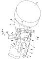
- Fig. 2
- einen Schnitt nach der Linie II-II der Fig.1.
- Fig. 1
- an oblique view from the front right of a passenger car with the cooler according to the invention;
- Fig. 2
- a section along the line II-II of Fig.1.
Ein Personenkraftwagen 1 umfaßt in dem dargestellten Bereich ein Rad 2 und einen
Bug 3 eines Aufbaus 4. Der Bug 3 wird durch Außenhautabschnitte 5, 6 definiert, die
Bestandteil eines sich zwischen Radausschnitten 7 erstreckenden Bugendteils 8 sind.
In einen durch die Außenhautabschnitte 5, 6 begrenzten Raum 9 des Bugs 3 - in
Fahrtrichtung vor dem Rad 2 - ist ein Kühler 10 mit einem etwa rechteckigen
Querschnitt eingebaut, dessen längere Seiten 11 quer zur Fahrzeuglängsrichtung A-A
verlaufen. Jedoch ist der Kühler 10, der ein den Ladungseinsatz einer nicht gezeigten
Brennkraftmaschine optimierender Ladeluftkühler ist, im wesentlichen senkrecht
eingesetzt. Im Außenhautabschnitt 5 sind Lufteinläße 12, 13, unter anderem für den
Kühler 10, vorgesehen.A passenger car 1 comprises a
Gemäß Fig. 2 weist der Außenhautabschnitt 6 eine Außenwandung 14 auf, die einen
ersten quer zur Fahrzeuglängsmittelebene - nicht gezeigt - hin verlaufenden
Formabschnitt 15 und einen zweiten aufrechten Formabschnitt 16 aufweist. Die
Formabschnitte 15, 16 sind bombiert oder konvex ausgeführt. Zwischen dem ersten
Formabschnitt 15 und dem zweiten Formabschnitt 16, die im Winkel zueinander
verlaufen, ist ein dritter Formabschnitt 17 vorgesehen, der als Rundung ausgeführt ist.
An die Formabschnitte 15, 16, 17 ist eine Außenkontur 18 des Kühlers 10 angepaßt,
und zwar von der Innenseite des Raumes 9 aus. Dabei ist ein etwa konstantes
Abstandsmaß Am zwischen den Formabschnitten 15, 16, 17 und der Außenkontur 18
relativ klein, wodurch der Kühler 10 nahe an den Außenhautabschnitt 6 herangeführt
ist.2, the
Die Außenkontur 18 umfaßt einen ersten Außenkonturabschnitt 19 und einen zweiten
Außenkonturabschnitt 20, die die Außenseite einer Zuführungsleitung 21 des Kühlers
10 bilden und entlang des ersten Formabschnitts 15 sowie des dritten Formabschnitts
17 verlaufen. Die Zuführungsleitung 21, die durch diese Ausbildung gekrümmt ist,
begrenzt einen aufrechte Seitenwandungen 22, 23 besitzenden Kühlerkörper 24 an
einer Unterseite 25. Die Zuführungsleitung 21 ist auf der dem Formabschnitt 16
abgekehrten Seite 26 mit einem Anschlußstutzen 27 versehen, über den von einem
nicht dargestellten Turbolader Luft in die Zuführungsleitung 21 und den Kühlerkörper
24 gelangt.The outer contour 18 comprises a first
Der Kühlerkörper 24 weist auf einer von der Zuführungsleitung 21 entfernt liegenden
Seite 28 eine Austrittsleitung 29 auf, die ebenfalls den Kühlerkörper 24 begrenzt und
auf der Seite 26 einen Anschlußstutzen 30 umfaßt, durch den gekühlte Luft zu einer
nicht gezeigten Ansauganlage der Brennkraftmaschine geleitet wird. Ein
Außenkonturabschnitt 31 der Austrittsleitung 29 ist an einen mit strichpunktierter Linie
dargestellten vierten Formabschnitt 32 der Außenwandung 12 angepaßt, und zwar
ähnlich wie die Außenkontur 18 an die entsprechenden Formabschnitte.The
Schließlich ist der Kühler 10 mit geeigneten Mitteln an einer vorhandenen
Trägerstruktur 33 des Aufbaus 4 befestigt.Finally, the
Claims (9)
Applications Claiming Priority (2)
| Application Number | Priority Date | Filing Date | Title |
|---|---|---|---|
| DE19923098 | 1999-05-20 | ||
| DE19923098A DE19923098C2 (en) | 1999-05-20 | 1999-05-20 | Coolers for internal combustion engines |
Publications (3)
| Publication Number | Publication Date |
|---|---|
| EP1053901A2 true EP1053901A2 (en) | 2000-11-22 |
| EP1053901A3 EP1053901A3 (en) | 2003-01-02 |
| EP1053901B1 EP1053901B1 (en) | 2005-09-28 |
Family
ID=7908586
Family Applications (1)
| Application Number | Title | Priority Date | Filing Date |
|---|---|---|---|
| EP00106381A Expired - Lifetime EP1053901B1 (en) | 1999-05-20 | 2000-03-24 | Radiator for internal combustion engine |
Country Status (4)
| Country | Link |
|---|---|
| US (1) | US6435295B1 (en) |
| EP (1) | EP1053901B1 (en) |
| JP (1) | JP2000351331A (en) |
| DE (2) | DE19923098C2 (en) |
Families Citing this family (8)
| Publication number | Priority date | Publication date | Assignee | Title |
|---|---|---|---|---|
| US20080053129A1 (en) * | 2003-01-08 | 2008-03-06 | Ise Corporation | Vehicle Rooftop Engine Cooling System and Method |
| US6910529B2 (en) * | 2003-01-08 | 2005-06-28 | Ise Corporation | Vehicle rooftop engine cooling system |
| US20060000429A1 (en) * | 2003-01-08 | 2006-01-05 | Stone Kevin T | Vehicle rooftop engine cooling system |
| US20070181442A1 (en) * | 2006-02-03 | 2007-08-09 | Applied Materials, Inc. | Method and apparatus for foam removal in an electrochemical mechanical substrate polishing process |
| DE102007028312A1 (en) * | 2007-06-20 | 2008-12-24 | Audi Ag | Cooler arrangement for use in passenger car, has cooler element expandable to another cooler element depending on assigned unit or component, where arrangement is modularly designed |
| DE102008063497A1 (en) * | 2008-12-17 | 2010-06-24 | Audi Ag | Motor vehicle, has radiator that is arranged between supporting component of body structure and outer covering part of vehicle, where radiator comprises pipes for gaseous medium which is to be cooled |
| DE102010010398A1 (en) | 2010-03-05 | 2011-09-08 | GM Global Technology Operations LLC , (n. d. Ges. d. Staates Delaware) | Front structure of a motor vehicle |
| KR101231539B1 (en) * | 2011-03-10 | 2013-02-07 | 기아자동차주식회사 | Wind Flux Concentration Guiding Device and Engine Room Layout Thereof |
Citations (1)
| Publication number | Priority date | Publication date | Assignee | Title |
|---|---|---|---|---|
| DE3930076C1 (en) | 1989-09-09 | 1991-02-14 | Mercedes-Benz Aktiengesellschaft, 7000 Stuttgart, De |
Family Cites Families (7)
| Publication number | Priority date | Publication date | Assignee | Title |
|---|---|---|---|---|
| GB279105A (en) * | 1926-10-15 | 1928-03-08 | Adolphe Kegresse | Improved method of mounting motor vehicle bonnets and radiators |
| DE2931812A1 (en) * | 1979-08-06 | 1981-02-26 | Heinrich Schlossmacher | Low drag radiator for car - has heat exchanger panels with interior ducts on exterior body sections |
| JPH05170135A (en) * | 1991-12-18 | 1993-07-09 | Mazda Motor Corp | Front body structure for automobile |
| US5359969A (en) * | 1994-01-05 | 1994-11-01 | Caterpillar Inc. | Intermittent cooling fan control |
| US5460420A (en) * | 1994-11-09 | 1995-10-24 | Mccord Winn Textron | Compartmentized plastic bumper |
| JPH08270444A (en) * | 1995-03-31 | 1996-10-15 | Hitachi Constr Mach Co Ltd | Cooling structure of construction equipment |
| DE19602186C1 (en) * | 1996-01-23 | 1997-05-22 | Porsche Ag | Front end vehicle cooling system |
-
1999
- 1999-05-20 DE DE19923098A patent/DE19923098C2/en not_active Expired - Fee Related
-
2000
- 2000-03-24 EP EP00106381A patent/EP1053901B1/en not_active Expired - Lifetime
- 2000-03-24 DE DE50011235T patent/DE50011235D1/en not_active Expired - Lifetime
- 2000-05-18 JP JP2000146430A patent/JP2000351331A/en not_active Withdrawn
- 2000-05-22 US US09/576,855 patent/US6435295B1/en not_active Expired - Fee Related
Patent Citations (1)
| Publication number | Priority date | Publication date | Assignee | Title |
|---|---|---|---|---|
| DE3930076C1 (en) | 1989-09-09 | 1991-02-14 | Mercedes-Benz Aktiengesellschaft, 7000 Stuttgart, De |
Also Published As
| Publication number | Publication date |
|---|---|
| DE19923098C2 (en) | 2003-02-20 |
| EP1053901B1 (en) | 2005-09-28 |
| EP1053901A3 (en) | 2003-01-02 |
| JP2000351331A (en) | 2000-12-19 |
| DE19923098A1 (en) | 2000-11-30 |
| US6435295B1 (en) | 2002-08-20 |
| DE50011235D1 (en) | 2005-11-03 |
Similar Documents
| Publication | Publication Date | Title |
|---|---|---|
| DE102007019539B4 (en) | Air supply device for the air conditioning of passenger compartments in airplanes | |
| EP0175939A2 (en) | Vehicle with an inlet conduit for a supercharged air cooler | |
| DE3338466A1 (en) | MOTOR VEHICLE, ESPECIALLY CARS | |
| DE112018000401T5 (en) | A MOTOR VEHICLE COMPRISING A MOTOR AIR INTAKE SYSTEM AND AIR FILTER HOUSING ARRANGEMENT, AND A METHOD FOR PASSING AIR TO AN AIR INTAKE OF A VEHICLE ENGINE | |
| DE2740918A1 (en) | COMBUSTION MACHINE WITH SOUND INSULATING CAPSULE AND WATER COOLER LOCATED OUTSIDE THE CAPSULE | |
| DE102017129199B4 (en) | Airflow management system for a vehicle | |
| DE1455760B2 (en) | COOLING DEVICE FOR AN ARMORED VEHICLE | |
| DE2612299A1 (en) | INSULATION DEVICE FOR ENGINE EXHAUST SYSTEMS | |
| EP1053901B1 (en) | Radiator for internal combustion engine | |
| EP1520771A1 (en) | Aerodynamic bottom cover for vehicle, more specifically for a car | |
| DE2527774A1 (en) | Inlet manifold for IC engines - is two part die casting joined at dividing plane | |
| DE4244039C2 (en) | Cooling module for internal combustion engines | |
| DE3024312A1 (en) | FRONT CONSTRUCTION OF A VEHICLE | |
| DE19943002C2 (en) | Cooling device for an internal combustion engine | |
| EP1044325B1 (en) | Method for producing doors, hoods or single parts made of sheet metal in automotive bodyshells | |
| DE10144015A1 (en) | Exhaust system for multi-cylinder internal combustion engines | |
| DE19509002C2 (en) | Thermostat mounting structure | |
| DE3537744A1 (en) | INTAKE DISTRIBUTION PIPE | |
| DE2158638C3 (en) | Motor vehicle, in particular passenger car | |
| DE10340952B4 (en) | Motor vehicle, preferably sports car | |
| DE10307979B4 (en) | Mudguards with integrated air supply system | |
| DE3531468C2 (en) | Air supply device for the engine of a truck | |
| DE3402731A1 (en) | Motor vehicle with a sound-insulating, encapsulated internal combustion engine | |
| DE19933283B4 (en) | Body front section | |
| DE10031369A1 (en) | Attachment arrangement for lighting module on motor vehicle has module joined in one piece to body part (fender cladding), movable with part between operating, non-operating positions |
Legal Events
| Date | Code | Title | Description |
|---|---|---|---|
| PUAI | Public reference made under article 153(3) epc to a published international application that has entered the european phase |
Free format text: ORIGINAL CODE: 0009012 |
|
| AK | Designated contracting states |
Kind code of ref document: A2 Designated state(s): AT BE CH CY DE DK ES FI FR GB GR IE IT LI LU MC NL PT SE |
|
| AX | Request for extension of the european patent |
Free format text: AL;LT;LV;MK;RO;SI |
|
| PUAL | Search report despatched |
Free format text: ORIGINAL CODE: 0009013 |
|
| AK | Designated contracting states |
Kind code of ref document: A3 Designated state(s): AT BE CH CY DE DK ES FI FR GB GR IE IT LI LU MC NL PT SE |
|
| AX | Request for extension of the european patent |
Free format text: AL;LT;LV;MK;RO;SI |
|
| 17P | Request for examination filed |
Effective date: 20030702 |
|
| AKX | Designation fees paid |
Designated state(s): DE FR GB IT |
|
| 17Q | First examination report despatched |
Effective date: 20040525 |
|
| GRAP | Despatch of communication of intention to grant a patent |
Free format text: ORIGINAL CODE: EPIDOSNIGR1 |
|
| GRAS | Grant fee paid |
Free format text: ORIGINAL CODE: EPIDOSNIGR3 |
|
| GRAA | (expected) grant |
Free format text: ORIGINAL CODE: 0009210 |
|
| AK | Designated contracting states |
Kind code of ref document: B1 Designated state(s): DE FR GB IT |
|
| REG | Reference to a national code |
Ref country code: GB Ref legal event code: FG4D Free format text: NOT ENGLISH |
|
| REF | Corresponds to: |
Ref document number: 50011235 Country of ref document: DE Date of ref document: 20051103 Kind code of ref document: P |
|
| GBT | Gb: translation of ep patent filed (gb section 77(6)(a)/1977) |
Effective date: 20051221 |
|
| ET | Fr: translation filed | ||
| PLBE | No opposition filed within time limit |
Free format text: ORIGINAL CODE: 0009261 |
|
| STAA | Information on the status of an ep patent application or granted ep patent |
Free format text: STATUS: NO OPPOSITION FILED WITHIN TIME LIMIT |
|
| 26N | No opposition filed |
Effective date: 20060629 |
|
| PGFP | Annual fee paid to national office [announced via postgrant information from national office to epo] |
Ref country code: GB Payment date: 20090325 Year of fee payment: 10 |
|
| REG | Reference to a national code |
Ref country code: FR Ref legal event code: TP |
|
| PGFP | Annual fee paid to national office [announced via postgrant information from national office to epo] |
Ref country code: IT Payment date: 20090323 Year of fee payment: 10 |
|
| REG | Reference to a national code |
Ref country code: FR Ref legal event code: CD |
|
| GBPC | Gb: european patent ceased through non-payment of renewal fee |
Effective date: 20100324 |
|
| REG | Reference to a national code |
Ref country code: FR Ref legal event code: TP |
|
| PG25 | Lapsed in a contracting state [announced via postgrant information from national office to epo] |
Ref country code: IT Free format text: LAPSE BECAUSE OF NON-PAYMENT OF DUE FEES Effective date: 20100324 Ref country code: GB Free format text: LAPSE BECAUSE OF NON-PAYMENT OF DUE FEES Effective date: 20100324 |
|
| PGFP | Annual fee paid to national office [announced via postgrant information from national office to epo] |
Ref country code: FR Payment date: 20110404 Year of fee payment: 12 |
|
| REG | Reference to a national code |
Ref country code: FR Ref legal event code: ST Effective date: 20121130 |
|
| PG25 | Lapsed in a contracting state [announced via postgrant information from national office to epo] |
Ref country code: FR Free format text: LAPSE BECAUSE OF NON-PAYMENT OF DUE FEES Effective date: 20120402 |
|
| PGFP | Annual fee paid to national office [announced via postgrant information from national office to epo] |
Ref country code: DE Payment date: 20130307 Year of fee payment: 14 |
|
| REG | Reference to a national code |
Ref country code: DE Ref legal event code: R119 Ref document number: 50011235 Country of ref document: DE |
|
| REG | Reference to a national code |
Ref country code: DE Ref legal event code: R119 Ref document number: 50011235 Country of ref document: DE Effective date: 20141001 |
|
| PG25 | Lapsed in a contracting state [announced via postgrant information from national office to epo] |
Ref country code: DE Free format text: LAPSE BECAUSE OF NON-PAYMENT OF DUE FEES Effective date: 20141001 |