EP1053837A2 - Shaving system and method - Google Patents
Shaving system and method Download PDFInfo
- Publication number
- EP1053837A2 EP1053837A2 EP00117862A EP00117862A EP1053837A2 EP 1053837 A2 EP1053837 A2 EP 1053837A2 EP 00117862 A EP00117862 A EP 00117862A EP 00117862 A EP00117862 A EP 00117862A EP 1053837 A2 EP1053837 A2 EP 1053837A2
- Authority
- EP
- European Patent Office
- Prior art keywords
- cartridge
- handle
- housing
- support structure
- recess
- Prior art date
- Legal status (The legal status is an assumption and is not a legal conclusion. Google has not performed a legal analysis and makes no representation as to the accuracy of the status listed.)
- Granted
Links
Images


Classifications
-
- B—PERFORMING OPERATIONS; TRANSPORTING
- B26—HAND CUTTING TOOLS; CUTTING; SEVERING
- B26B—HAND-HELD CUTTING TOOLS NOT OTHERWISE PROVIDED FOR
- B26B21/00—Razors of the open or knife type; Safety razors or other shaving implements of the planing type; Hair-trimming devices involving a razor-blade; Equipment therefor
- B26B21/40—Details or accessories
- B26B21/52—Handles, e.g. tiltable, flexible
- B26B21/528—Manufacture of razor handles
-
- B—PERFORMING OPERATIONS; TRANSPORTING
- B26—HAND CUTTING TOOLS; CUTTING; SEVERING
- B26B—HAND-HELD CUTTING TOOLS NOT OTHERWISE PROVIDED FOR
- B26B21/00—Razors of the open or knife type; Safety razors or other shaving implements of the planing type; Hair-trimming devices involving a razor-blade; Equipment therefor
- B26B21/08—Razors of the open or knife type; Safety razors or other shaving implements of the planing type; Hair-trimming devices involving a razor-blade; Equipment therefor involving changeable blades
- B26B21/14—Safety razors with one or more blades arranged transversely to the handle
- B26B21/22—Safety razors with one or more blades arranged transversely to the handle involving several blades to be used simultaneously
- B26B21/222—Safety razors with one or more blades arranged transversely to the handle involving several blades to be used simultaneously with the blades moulded into, or attached to, a changeable unit
- B26B21/225—Safety razors with one or more blades arranged transversely to the handle involving several blades to be used simultaneously with the blades moulded into, or attached to, a changeable unit the changeable unit being resiliently mounted on the handle
-
- B—PERFORMING OPERATIONS; TRANSPORTING
- B26—HAND CUTTING TOOLS; CUTTING; SEVERING
- B26B—HAND-HELD CUTTING TOOLS NOT OTHERWISE PROVIDED FOR
- B26B21/00—Razors of the open or knife type; Safety razors or other shaving implements of the planing type; Hair-trimming devices involving a razor-blade; Equipment therefor
- B26B21/40—Details or accessories
- B26B21/4012—Housing details, e.g. for cartridges
-
- B—PERFORMING OPERATIONS; TRANSPORTING
- B26—HAND CUTTING TOOLS; CUTTING; SEVERING
- B26B—HAND-HELD CUTTING TOOLS NOT OTHERWISE PROVIDED FOR
- B26B21/00—Razors of the open or knife type; Safety razors or other shaving implements of the planing type; Hair-trimming devices involving a razor-blade; Equipment therefor
- B26B21/40—Details or accessories
- B26B21/4068—Mounting devices; Manufacture of razors or cartridges
-
- B—PERFORMING OPERATIONS; TRANSPORTING
- B26—HAND CUTTING TOOLS; CUTTING; SEVERING
- B26B—HAND-HELD CUTTING TOOLS NOT OTHERWISE PROVIDED FOR
- B26B21/00—Razors of the open or knife type; Safety razors or other shaving implements of the planing type; Hair-trimming devices involving a razor-blade; Equipment therefor
- B26B21/40—Details or accessories
- B26B21/52—Handles, e.g. tiltable, flexible
- B26B21/521—Connection details, e.g. connection to razor heads
Definitions
- the invention relates to shaving systems having handles and replaceable cartridges.
- Shaving systems often consist of a handle and a replaceable cartridge in which one or more blades are mounted in a plastic housing. After the blades in a cartridge have become dull from use, the cartridge is discarded, and replaced on the handle with a new cartridge.
- the blades are resiliently mounted with respect to the cartridge housing and deflect under the force of skin contact during shaving.
- the connection of the cartridge to the handle provides a pivotal mounting of the cartridge with respect to the handle so that the cartridge angle adjusts to follow the contours of the surface being shaved.
- the cartridge can be biased toward an at rest position by the action of a spring-biased plunger (a cam follower) carried on the handle against a cam surface on the cartridge housing.
- the invention features a replaceable shaving cartridge having a housing carrying blades, a guard, a cap, and a camming surface.
- the cartridge also includes an interconnect member having a pivotal support structure that pivotally supports the housing and a base structure adapted to be removably and fixedly attached to a handle.
- the interconnect member provides access to the camming surface by a spring-biased cam follower on the handle.
- the invention features a replaceable shaving cartridge having a housing carrying blades, a guard, and a cap.
- the cartridge also includes an interconnect member having a pivotal support structure that pivotally supports the housing about a pivot axis and a base structure adapted to be removably and fixedly attached to an extension at an end of a handle.
- the handle extension has outer side surfaces
- the base structure has a recess with inwardly directed side surfaces that engage a sufficient number of the outer side surfaces on the handle extension so as to immovably position the base structure with respect to the handle extension.
- the base structure also has an opening to the recess along an axis that is nonparallel with respect to the pivot axis.
- the invention features a replaceable shaving cartridge having a housing carrying blades, a guard, and a cap.
- the cartridge also includes an interconnect member having a base structure adapted to be removably and fixedly attached to a handle extension that extends from an end of a handle along an extension axis.
- the handle extension has outer side surfaces and an asymmetrical section in a plane through the side surfaces perpendicular to the extension axis.
- the base structure has a recess that mates with the extension and has inwardly directed side surfaces that engage a sufficient number of the outer side surfaces along the asymmetrical extension so as to immovably position the base with respect to the extension and to ensure proper orientation of the housing with respect to the handle.
- the base structure has an opening to the recess along an axis that is perpendicular to the plane.
- the invention features, in general, a replaceable razor blade cartridge that includes a blade unit and cartridge connecting structure for connecting the blade unit to a handle.
- the cartridge connecting structure has inwardly directed surfaces that partially define a handle-receiving region and mate with outwardly directed surfaces on handle connecting structure of the handle.
- the cartridge connecting structure also has a connection entrance to the handle-receiving region and a projection that extends into the handle-receiving region.
- the projection has a blocking surface facing the opposite direction from the connection entrance to retain to handle connecting structure on the cartridge connecting structure.
- the invention features, in general, a replaceable razor blade cartridge that includes a blade unit that is pivotally connected to a cartridge connecting structure that includes a latching member that is movable to release the cartridge from a handle.
- the housing has a substantially unobstructed rinsing region under the blades;
- the pivotal support structure has a pivot axis in front of the blades in the region of the guard.
- the shape of the recess in the base may be a trapezoid, have six sides and/or be flat in a direction parallel to the blades.
- the base structure is snap fitted onto the handle; the base structure has a detent and the handle has a mating depression adapted to receive the detent; alternatively the handle has a detent and the base structure has a mating depression adapted to receive the detent; plural detents and depressions are used.
- the base structure is latchably secured to the handle.
- the housing and the interconnect member are made from separate pieces of plastic.
- the housing and the interconnect member are made of the same piece of plastic, and the pivotal support structure is provided by a living hinge.
- the pivotal support structure is provided by a flexible plastic hinge portion that is made of material that is more flexible than the housing and connects the housing and interconnect member at a pivot region.
- the pivotal support structure of the interconnect member includes two arms having ends retained in recesses with openings at two sides of the housing; the ends of the arms snap into the recesses of the housing; the recesses are covered by clips to retain the ends of the arms within the recesses; the arms have lower surfaces that slide on upwardly-directed arcuate surfaces on the housing.
- the housing has a camming surface for receiving a cam follower surface on a spring-biases plunger from the interconnect member;
- the interconnect member has an opening to receive the spring-biased plunger;
- the camming surface permits pivoting in only one direction from a rest position or permits different amounts of pivoting forward and backward from the rest position;
- the housing also has front and back stop surfaces that interact with the interconnect member.
- the blades are loaded into the housing from a top side of the housing; the blades are retained in the housing by clips that retain the interconnect member at a bottom side of the housing; the housing carries three blades; the blades are spring biased (e.g., to blades may be resiliently supported in the housing by spring arms integral with the housing; the guard is made of an elastomer and has flexible fins to engage the user's skin.
- the invention features a method of making a replaceable shaving cartridge.
- a housing for carrying blades, an interconnect member having a pivotal support structure and a base structure adapted to be removably and fixedly attached to a handle are provided.
- the pivotal support structure is inserted into a recess in the housing.
- the pivotal support structure is retained in the recess.
- Implementations of the invention may include one or more of the following features.
- the retaining step includes snap fitting and/or adding a clip.
- the blades may be added to the housing before adding a clip to retain the blades with the clip.
- the invention features a shaving razor handle having an elongated band gripping structure and a cartridge support structure extending from an end of the hand gripping structure.
- the cartridge support structure has outer side surfaces that mate with inwardly directed surfaces of a recess on a cartridge and an end surface with an opening.
- a spring-biased plunger is retained in the cartridge support structure and extends through the opening of the cartridge support structured.
- Certain implementations of the invention may include one or more of the following features.
- the outer side surfaces provide an asymmetrical shape to ensure proper orientation of the cartridge with respect to the handle;
- the spring-biased plunger is guided by a slot in the cartridge support structure;
- an ejector and snap fit ejector button are used to eject the cartridge;
- the ejector button has an inclined surface to facilitate attachment to the cartridge support structure;
- the ejector button slides on a guide surface in the cartridge support structure when pushing the ejector;
- the cartridge support structure has a truck, and the ejector button has a groove that slides on the track.
- the plunger and the ejector are biased in opposite directions by a spring;
- the plunger has a stop which retains the plunger within the cartridge support structure;
- the plunger has an arm with an inclined surface, the inclined surface and the stop extending above the plunger and being retained in the slot in the cartridge support structure to guide the plunger;
- the stop has an inclined surface to permit the stop to be inserted into the cartridge support structure;
- the plunger has a rear guide member to further guide the plunger.
- the first end of the spring biases the plunger against the stop, and a second end of the spring biases the ejector against a back surface of the cartridge support structure; the ejector button and the cartridge support structure have spring support portions to capture and guide the spring.
- the ejector is a U-shaped clip having ejector arms and narrower portions that engage the ejector button
- the cartridge support structure has a mating guide surface along which the ejector arms and the narrower portions slide.
- the cartridge support structure and the elongated gripping structure are made of a single piece of plastic.
- the cartridge support nature and the elongated gripping structure are made from separate pieces of plastic.
- the invention features a shaving razor handle having an elongated hand gripping structure and a cartridge support structure extending from an end of the hand gripping structure.
- the elongated hand gripping structure includes a gripping portion including an elastomeric plastic outer gripping layer and a nonelastomeric plastic support layer thereunder having extensions that are press-fitted into the elongated band gripping structure.
- the elongated hand gripping structure is made of plastic and defines a recess in which a weight is disposed; the plastic is metallic-colored plastic.
- the invention features a method of making a shaving razor handle.
- An elongated hand gripping structure and an attached cartridge support structure extending from an end of the elongated hand gripping structure and having a recess therein with an inwardly directed stop surface are provided.
- a spring and a plunger having an outwardly directed stop surface are inserted into the recess until the outwardly directed stop surface passes the inwardly directed stop surface and is retained by the inwardly directed stop surface.
- Certain implementations of the invention may include one or more of the following features: the ejector is inserted into the recess; an ejector button is inserted into the cartridge support structure to push the ejector.
- the invention features a razor including a handle and a replaceable shaving cartridge including a pivotal housing and an interconnect member.
- the housing carries blades, a guard, a cap, and has a camming surface.
- the interconnect member has a pivotal support structure that pivotally supports the housing and a central base structure having a recess and an opening from the recess facing the camming surface.
- the handle has a cartridge support structure shaped to mate with the recess and a spring biased plunger with a cam follower surface extending from the cartridge support structure and through the opening to act on the camming surface to bias the housing.
- the invention features a razor having a replaceable shaving cartridge including a housing and an interconnect member.
- the housing carries at least one blade, a guard, and a cap.
- the interconnect member has a pivotal support structure and a central base structure with a recess.
- a handle has a cartridge support structure including an extension shaped to mate with the recess, and a stepped portion has the same shape as the central base structure so as to continue the shape from the cartridge support structure to the central base structure.
- the central base structure way be flat along an axis that is parallel to the blade, and may also have a curved or beveled shape.
- shaving razor 10 includes handle 12 and replaceable shaving cartridge 14. As shown in Fig. 2, cartridge 14 is removable from handle 12.
- Cartridge 14 includes housing 16, which carries three blades 18, guard 20 and cap 22.
- Cartridge 14 also includes interconnect member 24 on which housing 16 is pivotally mounted.
- Interconnect member 24 includes base 27, which removably and fixedly attaches to asymmetrical extension 26 (Fig. 19) on handle 12, and two arms 28 that pivotally support housing 16 at its two sides.
- handle 12 includes metallic colored plastic component 30 as a primary structural member on which the remaining components are mounted.
- Elongated portion 32 of component 30 has recess 34 for receiving metal (e.g., zinc) weight 36, which is sandwiched between plastic gripping portions 38 and 40 to provide a hand-gripping structure in the completed unit.
- Plastic gripping portions 38 and 40 are made of an elastomeric plastic outer gripping layer 37 (e.g., thermoplastic elastomer) and a nonelastomeric plastic support layer 39 (e.g., of acrylonitrile butadiene styrene) thereunder made by two-color molding.
- the nonelastomeric plastic support layer has extensions 41 that are press-fitted into weight 36 in elongated portion 32.
- Fig. 3A illustrates the undeformed shape of extension 41 (in phantom) and the interference fit made by it at projection 43.
- Cartridge support structure 42 extends from the end of elongated portion 32. It includes trapezoid shaped extension 26 (see Fig. 19) and the components that provide a spring-biased plunger action for biasing of housing 16 relative to interconnect member 24. It also includes components that provide for ejection of cartridge 14 from handle 12.
- Spring-biased plunger 44, spring 46, and U-shaped ejector 48 are received within recess 49 of cartridge support structure 42.
- Ejector button 50 is received in opening 52 on the top surface of support structure 42 and has bottom extensions 54 that are received within rectangular region 56 at the back narrow portion of ejector 48.
- housing 16 of cartridge 14 has inwardly facing slots 58 in side walls 60 for receiving the edges of the base portions 59 of blades 18 and respective resilient arms 62 (Fig. 15) on which each blade 18 is resiliently supported. Blades 18 are located in a substantially unobstructed region 64 between side walls 60 to provide for ease of rinsing of the cartridge during use,
- Cap 22 provides a lubricous shaving aid and is received in slot 66 at the rear of housing 16.
- Cap 22 way be made of a material comprising a mixture of a hydrophobic material and a water leachable hydrophilic polymer material, as is known in the art and is described, e.g., in U.S. Patents Nos. 5,113,585 and 5,454,164, which are hereby incorporated by reference.
- Guard 20 includes a finned elastomeric unit mounted at the front of housing 16 to engage and stretch the user's skin; other skin engaging protrusions, e.g., as described in U.S. Patent No. 5,191,712, which is hereby incorporated by reference, can be used.
- Clips 68 are secured at the respective sides of housing 16 inside of raised edges 70 of side walls 60 in order to retain blades 18 within housing 16 and to locate the cutting edges of the spring-biased blades at a desired exposure.
- Base structure 27 has an opening 74 at the top through which spring-biased plunger 44 of the handle passes to act on a cam surface (not shown in Fig. 4) on the bottom of housing 16.
- Base structure 27 may have a curved or beveled shape.
- Figs. 5-12 and 19 show the details of plunger 44, ejector 48, button 50, and cartridge support structure 42.
- recess 49 within cartridge support structure 42 has wide front portion 76 for receiving arms 78 of ejector 48 (Fig. 10) and a narrower portion 80 for receiving narrower portion 82 of ejector 48.
- Rectangular region 56 at narrow portion 82 of ejector 48 is generally aligned with opening 52 at the upper surface of support structure 42, though rectangular region 56 is movable with respect to opening 52 along slide axis 83 as ejector 48 is pushed outward by ejector button 50.
- each extension 54 of ejector button 50 has an outwardly directed groove 84 that slides on a respective track 86 within opening 52 along axis 83.
- the upper surfaces 85 defining grooves 84 slide on the upper surfaces 89 of tracks 86, and the lower surfaces 91 defining groves 84 effect capture on or abut the lower surfaces 93 of track 86.
- Extensions 54 have inclined surfaces 87 that coact with the curved upper corners of tracks 86 to deflect extensions 54 inward as button 50 is inserted into cartridge support structure 42. When grooves 84 on extension 54 align with tracks 86, extensions 54 substantially return to their undeflected position and lock ejector button 50 in place within opening 52.
- Ejector 48 is placed within recess 49 before button 50 is inserted so that the ends of extensions 54 will be located within rectangular region 56 so as to retain ejector 48 within cartridge support structure 42. Extensions 54 push against surfaces 94 of ejector 48 when ejector button 50 is pushed toward the end of handle 12. After button 50 has been inserted, upper vertical surfaces 96 of extensions 54 sit within the space between upper surfaces 98 of opening 52.
- Spring 46 extends through the space between extensions 54 and is guided by the curved lower surface of spring guide 90 on button 50. As shown in Fig. 8, the lower surface defining recess 49 also has a curved central portion 92 to receive and guide spring 46.
- plunger 44 has flat body 106, cylindrical rear extension 100 for receiving spring 46 (Fig. 3), curved front cam follower portion 102 for acting on the camming surface 136 (Fig. 18) of housing 16, side arms 104, and aligned rear guide portions 108.
- Flat body 106 is positioned within the flat front portion of recess 49 (Fig. 6).
- the portions of side arms 104 and aligned rear guide portions 108 above and below body 106 are located within slots 110, 112 located on both sides of asymmetrical extension 26.
- Side arms 104 have stop surfaces 114 that prevent forward movement of plunger 44 beyond the front and of slot 110 and 112.
- the portions of side arms 104 and guide portions 108 above and below recess 49 within slots 110, 112 act as guides to guide the sliding action of plunger 44 along axis 83.
- Side arms 104 have inclined surfaces 120 to cause downward biasing of arms 104 when plunger 44 is inserted into recess 49 until stop surfaces 114 advance past the front ends of slots 110, 112 and stop surfaces 114 snap into position within the respective slot. Because slots 110, 112 are provided on both sides of asymmetrical extension 26, plunger 44 can be inserted in either position orientation, with the stop surface 114 directed into slot 110 or 112.
- one surface of asymmetrical extension 26 includes depressions 122 for receiving detents within base structure 27 of cartridge 14 in order to retain cartridge 14 on extension 26.
- the hand gripping components are assembled by first inserting weight 36 into recess 34, and then press-fitting extensions 41 of components 38, 40 into aligned apertures in weight 36. Weight 36 and components 38, 40 are locked in place by the interference fit between extensions 41 and projections 43, and elastomeric layer 37 deforms to provide a seal between the side walls of elongated portion 32 of plastic component 30 and weight 36. (Fig. 3A shows the undeformed shapes of the components in phantom.)
- ejector 48 is first inserted into recess 49.
- Spring 46 and plunger 44 are then inserted.
- Inclined surfaces 120 of side arms 104 are biased during insertion toward the middle of the recess and then snap into slot 110 or 112 (depending on plunger orientation) locking plunger 44, spring 46, and ejector 48 in place in cartridge support structure 42.
- Spring 46 acts both to bias ejector 48 backward against the surfaces of recess 49 and button extensions 54 and to bias plunger 44 forward, stop surfaces 114 being biased against the forward edges of slot 110 or 112.
- Button 50 is inserted into opening 52 after ejector 48 has been inserted into position.
- Inclined surfaces 87 are biased inward by the curved upper portions of rails 86, and ejector button 50 is snapped into place with tracks 86 being located within grooves 84.
- Figs. 13-18 show further details of replaceable cartridge 14 and its pivotal movement.
- interconnect member 24 is shown assembled to housing 16 with pivotal support ends 72 retained by clips 68. It is seen that base structure 27 has a trapezoidal shaped recess 130 that has the same shape as extension 26 and mates with extension 26.
- housing 16 shown before the other cartridge components have been assembled on it, has recesses 131 in which the pivotal support ends 72 on the ends of arms 28 are received. Arms 28 deflect as support ends 72 are inserted trough the openings to recesses 131 and then snap back to an undeflected orientation after ends 72 are within recesses 131 to retain ends 72 in place.
- detents 132 within recess 130 of base 27 mate with depressions 122 of asymmetrical extension 26.
- opening 74 which permits spring-biased plunger 44 to extend through base 27 and to interact with camming surface 136 on the bottom of housing 16.
- each pivotal support end 72 has a lower curved surface 138 that slides on upper curved surface 140 of housing 16, providing a pivot axis at the center of a circle that includes surface 140.
- the pivot axis thus is in front of the blades in the region of guard 20.
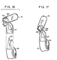
- Fig. 16 shows housing 16 in an unbiased position in which pivotal support ends 72 support the front surface of guide wall 162.
- Fig. 17 shows the forwardly biased position for housing 16, in which case the forward surface of pivot support ends 72 are pushed up against a forward wall portion of housing 16. This is the at rest position for housing 16 prior to shaving.
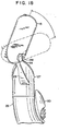
- the forwardly-biased at rest position is achieved by contouring camming surface 136 so that the plunger 44 having cam follower surface 102 has an at rest position near the front of housing 16, as shown in Fig. 18.
- Fig. 18 shows the range of pivotal motion for housing 16.
- cap 22 will initially contact the user's skin, and housing 16 will pivot clockwise and generally follow the contours of the user's face, being biased by plunger 44.
- the cap up initial orientation will cause the blade closer to cap 22 to initially be pushed against the skin more than the blades closer to the guard.
- the pivot at the region of guard and the light return force cause the cartridge to be "guard heavy" during shaving, with a higher load on the guard than the cap.
- the three blades are provided with progressive initial exposures, defined as the perpendicular distance or height of the blade edge measured with respect to a plane tangential to the skin contacting surfaces of the cartridge components immediately in front of and behind each blade.
- the primary blade has a negative initial exposure
- the second blade has zero initial exposure
- the third blade has positive initial exposure.
- the spring constants and preloads for the blades are the same, and the blades have "progressive force" distribution during shaving; i.e., the force on the third blade is greater than the force on the first blade, and the force on the second blade is intermediate to the forces on the first and third blades or equal to the force on either the first or third blade. It is believed that beneficial shaving results are achieved when cartridges with three resiliently mounted blades exhibit, during shaving, such a progressive force pattern.
- the base structure could be held on the housing with a releasable latch.
- the blades could be loaded from the bottom instead of the top.
- the cartridge support structure could be made as a unit separate from the handle and attached to it. In place of trapezoidal extension 26 (Fig. 19), a six-sided extension 226 (Fig. 20), or other asymmetrical shape could be employed.
- the pivotal connection could be provided by pins in respective holes, shell bearings, and other techniques.
- the pivotal support structure could be provided by a flexible plastic hinge portion 200 that is made of material that is more flexible than the housing 202 and connects the housing 202 and interconnect member 204 at a pivot region 206; these components could be made by two-color molding.
- the housing 208 and the interconnect member 210 may be made of the same piece of plastic, and the pivotal support structure may be provided by a living hinge 212.
- a living hinge could also be used with housings and interconnect members of different plastics.
Abstract
Description
- The invention relates to shaving systems having handles and replaceable cartridges.
- Shaving systems often consist of a handle and a replaceable cartridge in which one or more blades are mounted in a plastic housing. After the blades in a cartridge have become dull from use, the cartridge is discarded, and replaced on the handle with a new cartridge. In some shaving systems the blades are resiliently mounted with respect to the cartridge housing and deflect under the force of skin contact during shaving. In some shaving systems the connection of the cartridge to the handle provides a pivotal mounting of the cartridge with respect to the handle so that the cartridge angle adjusts to follow the contours of the surface being shaved. In such systems, the cartridge can be biased toward an at rest position by the action of a spring-biased plunger (a cam follower) carried on the handle against a cam surface on the cartridge housing.
- In general, in one aspect, the invention features a replaceable shaving cartridge having a housing carrying blades, a guard, a cap, and a camming surface. The cartridge also includes an interconnect member having a pivotal support structure that pivotally supports the housing and a base structure adapted to be removably and fixedly attached to a handle. The interconnect member provides access to the camming surface by a spring-biased cam follower on the handle.
- In general, in another aspect, the invention features a replaceable shaving cartridge having a housing carrying blades, a guard, and a cap. The cartridge also includes an interconnect member having a pivotal support structure that pivotally supports the housing about a pivot axis and a base structure adapted to be removably and fixedly attached to an extension at an end of a handle. The handle extension has outer side surfaces, and the base structure has a recess with inwardly directed side surfaces that engage a sufficient number of the outer side surfaces on the handle extension so as to immovably position the base structure with respect to the handle extension. The base structure also has an opening to the recess along an axis that is nonparallel with respect to the pivot axis.
- In general, in another aspect, the invention features a replaceable shaving cartridge having a housing carrying blades, a guard, and a cap. The cartridge also includes an interconnect member having a base structure adapted to be removably and fixedly attached to a handle extension that extends from an end of a handle along an extension axis. The handle extension has outer side surfaces and an asymmetrical section in a plane through the side surfaces perpendicular to the extension axis. The base structure has a recess that mates with the extension and has inwardly directed side surfaces that engage a sufficient number of the outer side surfaces along the asymmetrical extension so as to immovably position the base with respect to the extension and to ensure proper orientation of the housing with respect to the handle. The base structure has an opening to the recess along an axis that is perpendicular to the plane.
- In one aspect, the invention features, in general, a replaceable razor blade cartridge that includes a blade unit and cartridge connecting structure for connecting the blade unit to a handle. The cartridge connecting structure has inwardly directed surfaces that partially define a handle-receiving region and mate with outwardly directed surfaces on handle connecting structure of the handle. The cartridge connecting structure also has a connection entrance to the handle-receiving region and a projection that extends into the handle-receiving region. The projection has a blocking surface facing the opposite direction from the connection entrance to retain to handle connecting structure on the cartridge connecting structure.
- In another aspect the invention features, in general, a replaceable razor blade cartridge that includes a blade unit that is pivotally connected to a cartridge connecting structure that includes a latching member that is movable to release the cartridge from a handle.
- Certain implementations of the invention include one or more of the following features.
- In certain implementations: the housing has a substantially unobstructed rinsing region under the blades; the pivotal support structure has a pivot axis in front of the blades in the region of the guard. The shape of the recess in the base may be a trapezoid, have six sides and/or be flat in a direction parallel to the blades.
- In certain implementations: the base structure is snap fitted onto the handle; the base structure has a detent and the handle has a mating depression adapted to receive the detent; alternatively the handle has a detent and the base structure has a mating depression adapted to receive the detent; plural detents and depressions are used. Alternatively, the base structure is latchably secured to the handle.
- In certain implementations: the housing and the interconnect member are made from separate pieces of plastic. Alternatively, the housing and the interconnect member are made of the same piece of plastic, and the pivotal support structure is provided by a living hinge. Alternatively, the pivotal support structure is provided by a flexible plastic hinge portion that is made of material that is more flexible than the housing and connects the housing and interconnect member at a pivot region.
- In certain implementations: the pivotal support structure of the interconnect member includes two arms having ends retained in recesses with openings at two sides of the housing; the ends of the arms snap into the recesses of the housing; the recesses are covered by clips to retain the ends of the arms within the recesses; the arms have lower surfaces that slide on upwardly-directed arcuate surfaces on the housing.
- In certain implementations: the housing has a camming surface for receiving a cam follower surface on a spring-biases plunger from the interconnect member; the interconnect member has an opening to receive the spring-biased plunger; the camming surface permits pivoting in only one direction from a rest position or permits different amounts of pivoting forward and backward from the rest position; the housing also has front and back stop surfaces that interact with the interconnect member.
- In certain implementations: the blades are loaded into the housing from a top side of the housing; the blades are retained in the housing by clips that retain the interconnect member at a bottom side of the housing; the housing carries three blades; the blades are spring biased (e.g., to blades may be resiliently supported in the housing by spring arms integral with the housing; the guard is made of an elastomer and has flexible fins to engage the user's skin.
- In general, in another aspect, the invention features a method of making a replaceable shaving cartridge. A housing for carrying blades, an interconnect member having a pivotal support structure and a base structure adapted to be removably and fixedly attached to a handle are provided. The pivotal support structure is inserted into a recess in the housing. The pivotal support structure is retained in the recess.
- Implementations of the invention may include one or more of the following features. The retaining step includes snap fitting and/or adding a clip. The blades may be added to the housing before adding a clip to retain the blades with the clip.
- In general, in another aspect, the invention features a shaving razor handle having an elongated band gripping structure and a cartridge support structure extending from an end of the hand gripping structure. The cartridge support structure has outer side surfaces that mate with inwardly directed surfaces of a recess on a cartridge and an end surface with an opening. A spring-biased plunger is retained in the cartridge support structure and extends through the opening of the cartridge support structured.
- Certain implementations of the invention may include one or more of the following features.
- In certain implementations: the outer side surfaces provide an asymmetrical shape to ensure proper orientation of the cartridge with respect to the handle; the spring-biased plunger is guided by a slot in the cartridge support structure; an ejector and snap fit ejector button are used to eject the cartridge; the ejector button has an inclined surface to facilitate attachment to the cartridge support structure; the ejector button slides on a guide surface in the cartridge support structure when pushing the ejector; the cartridge support structure has a truck, and the ejector button has a groove that slides on the track.
- In certain implementations: the plunger and the ejector are biased in opposite directions by a spring; the plunger has a stop which retains the plunger within the cartridge support structure; the plunger has an arm with an inclined surface, the inclined surface and the stop extending above the plunger and being retained in the slot in the cartridge support structure to guide the plunger; the stop has an inclined surface to permit the stop to be inserted into the cartridge support structure; the plunger has a rear guide member to further guide the plunger.
- In certain implementations: the first end of the spring biases the plunger against the stop, and a second end of the spring biases the ejector against a back surface of the cartridge support structure; the ejector button and the cartridge support structure have spring support portions to capture and guide the spring.
- In certain implementations: the ejector is a U-shaped clip having ejector arms and narrower portions that engage the ejector button, and the cartridge support structure has a mating guide surface along which the ejector arms and the narrower portions slide.
- In certain implementations: the cartridge support structure and the elongated gripping structure are made of a single piece of plastic. Alternatively, the cartridge support nature and the elongated gripping structure are made from separate pieces of plastic.
- In general, in another aspect, the invention features a shaving razor handle having an elongated hand gripping structure and a cartridge support structure extending from an end of the hand gripping structure. The elongated hand gripping structure includes a gripping portion including an elastomeric plastic outer gripping layer and a nonelastomeric plastic support layer thereunder having extensions that are press-fitted into the elongated band gripping structure.
- In certain implementations: the elongated hand gripping structure is made of plastic and defines a recess in which a weight is disposed; the plastic is metallic-colored plastic.
- In general, in another aspect, the invention features a method of making a shaving razor handle. An elongated hand gripping structure and an attached cartridge support structure extending from an end of the elongated hand gripping structure and having a recess therein with an inwardly directed stop surface are provided. A spring and a plunger having an outwardly directed stop surface are inserted into the recess until the outwardly directed stop surface passes the inwardly directed stop surface and is retained by the inwardly directed stop surface.
- Certain implementations of the invention may include one or more of the following features: the ejector is inserted into the recess; an ejector button is inserted into the cartridge support structure to push the ejector.
- In general, in another aspect, the invention features a razor including a handle and a replaceable shaving cartridge including a pivotal housing and an interconnect member. The housing carries blades, a guard, a cap, and has a camming surface. The interconnect member has a pivotal support structure that pivotally supports the housing and a central base structure having a recess and an opening from the recess facing the camming surface. The handle has a cartridge support structure shaped to mate with the recess and a spring biased plunger with a cam follower surface extending from the cartridge support structure and through the opening to act on the camming surface to bias the housing.
- In general, in another aspect, the invention features a razor having a replaceable shaving cartridge including a housing and an interconnect member. The housing carries at least one blade, a guard, and a cap. The interconnect member has a pivotal support structure and a central base structure with a recess. A handle has a cartridge support structure including an extension shaped to mate with the recess, and a stepped portion has the same shape as the central base structure so as to continue the shape from the cartridge support structure to the central base structure.
- Certain implementations of the invention may include one or more of the following features; the central base structure way be flat along an axis that is parallel to the blade, and may also have a curved or beveled shape.
- Other advantages and features of the invention will be apparent from the detailed description of preferred embodiments thereof and from the claims.
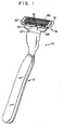
- Fig. 1 is a perspective view of a shaving razor according to the invention.
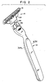
- Fig. 2 is a perspective view showing a handle and a replaceable cartridge of the Fig. 1 razor separated from each other.
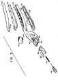
- Fig. 3 is an exploded view of the components of the Fig. 2 handle.
- Fig. 3A is a diagrammatic sectional view, taken at 3A-3A of Fig. 2, of the Fig. 2 handle.
- Fig. 4 is an exploded view of the components of the Fig. 2 replaceable cartridge.
- Fig. 4A is an exploded sectional view, taken at 4A-4A of Fig. 14, of the components of the Fig. 2 replaceable cartridge.
- Fig. 5 is a partial plan view showing a cartridge support structure at the end of the Fig. 2 handle.
- Fig. 6 is an elevation of a plunger of the Fig. 2 handle.
- Fig. 7 is a partial sectional view, taken at 7-7 of Fig. 5, of the Fig. 5 cartridge support structure.
- Fig. 8 is a sectional view taken at 8-8 of Fig. 5, of the Fig. 5 cartridge support structure.
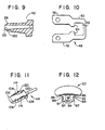
- Fig. 9 is a partial sectional view, taken at 9-9 of Fig. 5, of the Fig. 5 cartridge support structure.
- Fig. 10 is a plan view of an ejector used in the Fig. 5 cartridge support structure.
- Fig. 11 is a perspective view of the Fig. 6 plunger.
- Fig. 12 is an elevation of an ejector button used in the Fig. 5 cartridge support structure.
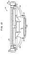
- Fig. 13 is an elevation of the Fig. 2 replaceable cartridge.
- Fig. 14 is a plan view of the Fig. 13 replaceable cartridge.
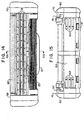
- Fig. 15 is a bottom view of the Fig. 13 replaceable cartridge.
- Fig. 16 is a side view, partially broken away, showing a housing of the Fig. 13 cartridge in an unbiased pivotal position with respect to a base structure of the cartridge prior to connection to a handle.
- Fig. 17 is a side view, partially broken away, of the Fig. 13 cartridge in a biased position after connection to a handle.
- Fig. 18 is a side view, partially broken away, showing the range of pivotal movement of the Fig. 13 replaceable cartridge.
- Fig. 19 is a sectional view of an extension of the Fig. 2 handle.
- Fig. 20 is a sectional view of an alternative embodiment of an extension of the Fig. 2 handle.
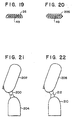
- Figs. 21 and 22 are side views of alternative embodiments of cartridges having different pivotal support structures.
-
- Referring to Figs. 1 and 2, shaving
razor 10 includeshandle 12 andreplaceable shaving cartridge 14. As shown in Fig. 2,cartridge 14 is removable fromhandle 12.Cartridge 14 includeshousing 16, which carries threeblades 18,guard 20 andcap 22.Cartridge 14 also includesinterconnect member 24 on whichhousing 16 is pivotally mounted.Interconnect member 24 includesbase 27, which removably and fixedly attaches to asymmetrical extension 26 (Fig. 19) onhandle 12, and twoarms 28 that pivotally supporthousing 16 at its two sides. - Referring to Fig. 3, handle 12 includes metallic
colored plastic component 30 as a primary structural member on which the remaining components are mounted.Elongated portion 32 ofcomponent 30 hasrecess 34 for receiving metal (e.g., zinc)weight 36, which is sandwiched between plasticgripping portions gripping portions extensions 41 that are press-fitted intoweight 36 inelongated portion 32. Fig. 3A illustrates the undeformed shape of extension 41 (in phantom) and the interference fit made by it atprojection 43. -
Cartridge support structure 42 extends from the end ofelongated portion 32. It includes trapezoid shaped extension 26 (see Fig. 19) and the components that provide a spring-biased plunger action for biasing ofhousing 16 relative to interconnectmember 24. It also includes components that provide for ejection ofcartridge 14 fromhandle 12. - Spring-biased
plunger 44,spring 46, andU-shaped ejector 48 are received withinrecess 49 ofcartridge support structure 42.Ejector button 50 is received in opening 52 on the top surface ofsupport structure 42 and hasbottom extensions 54 that are received withinrectangular region 56 at the back narrow portion ofejector 48. - Referring to Figs. 4, 4A and 15,
housing 16 ofcartridge 14 has inwardly facingslots 58 inside walls 60 for receiving the edges of thebase portions 59 ofblades 18 and respective resilient arms 62 (Fig. 15) on which eachblade 18 is resiliently supported.Blades 18 are located in a substantiallyunobstructed region 64 betweenside walls 60 to provide for ease of rinsing of the cartridge during use, -
Cap 22 provides a lubricous shaving aid and is received inslot 66 at the rear ofhousing 16.Cap 22 way be made of a material comprising a mixture of a hydrophobic material and a water leachable hydrophilic polymer material, as is known in the art and is described, e.g., in U.S. Patents Nos. 5,113,585 and 5,454,164, which are hereby incorporated by reference.Guard 20 includes a finned elastomeric unit mounted at the front ofhousing 16 to engage and stretch the user's skin; other skin engaging protrusions, e.g., as described in U.S. Patent No. 5,191,712, which is hereby incorporated by reference, can be used.Clips 68 are secured at the respective sides ofhousing 16 inside of raisededges 70 ofside walls 60 in order to retainblades 18 withinhousing 16 and to locate the cutting edges of the spring-biased blades at a desired exposure. -
Clips 68 also wrap around the bottom ofhousing 16 and prevent the removal of pivotal support ends 72 ofarms 28 ofinterconnect member 24.Base structure 27 has anopening 74 at the top through which spring-biasedplunger 44 of the handle passes to act on a cam surface (not shown in Fig. 4) on the bottom ofhousing 16.Base structure 27 may have a curved or beveled shape. - Figs. 5-12 and 19 show the details of
plunger 44,ejector 48,button 50, andcartridge support structure 42. Referring to Fig. 5,recess 49 withincartridge support structure 42 has widefront portion 76 for receivingarms 78 of ejector 48 (Fig. 10) and anarrower portion 80 for receivingnarrower portion 82 ofejector 48.Rectangular region 56 atnarrow portion 82 ofejector 48 is generally aligned with opening 52 at the upper surface ofsupport structure 42, thoughrectangular region 56 is movable with respect to opening 52 alongslide axis 83 asejector 48 is pushed outward byejector button 50. - Referring to Figs. 8 and 12, each
extension 54 ofejector button 50 has an outwardly directedgroove 84 that slides on arespective track 86 within opening 52 alongaxis 83. Theupper surfaces 85defining grooves 84 slide on theupper surfaces 89 oftracks 86, and thelower surfaces 91 defininggroves 84 effect capture on or abut thelower surfaces 93 oftrack 86.Extensions 54 have inclinedsurfaces 87 that coact with the curved upper corners oftracks 86 to deflectextensions 54 inward asbutton 50 is inserted intocartridge support structure 42. Whengrooves 84 onextension 54 align withtracks 86,extensions 54 substantially return to their undeflected position and lockejector button 50 in place withinopening 52.Ejector 48 is placed withinrecess 49 beforebutton 50 is inserted so that the ends ofextensions 54 will be located withinrectangular region 56 so as to retainejector 48 withincartridge support structure 42.Extensions 54 push againstsurfaces 94 ofejector 48 whenejector button 50 is pushed toward the end ofhandle 12. Afterbutton 50 has been inserted, uppervertical surfaces 96 ofextensions 54 sit within the space betweenupper surfaces 98 ofopening 52. - Spring 46 (Fig. 3) extends through the space between
extensions 54 and is guided by the curved lower surface ofspring guide 90 onbutton 50. As shown in Fig. 8, the lowersurface defining recess 49 also has a curvedcentral portion 92 to receive and guidespring 46. - As shown in Figs. 6 and 11,
plunger 44 hasflat body 106, cylindrical rear extension 100 for receiving spring 46 (Fig. 3), curved frontcam follower portion 102 for acting on the camming surface 136 (Fig. 18) ofhousing 16,side arms 104, and alignedrear guide portions 108.Flat body 106 is positioned within the flat front portion of recess 49 (Fig. 6). The portions ofside arms 104 and alignedrear guide portions 108 above and belowbody 106 are located withinslots asymmetrical extension 26.Side arms 104 havestop surfaces 114 that prevent forward movement ofplunger 44 beyond the front and ofslot side arms 104 and guideportions 108 above and belowrecess 49 withinslots plunger 44 alongaxis 83. -
Side arms 104 have inclinedsurfaces 120 to cause downward biasing ofarms 104 whenplunger 44 is inserted intorecess 49 until stop surfaces 114 advance past the front ends ofslots surfaces 114 snap into position within the respective slot. Becauseslots asymmetrical extension 26,plunger 44 can be inserted in either position orientation, with thestop surface 114 directed intoslot - Referring to Figs. 5 and 9, one surface of
asymmetrical extension 26 includesdepressions 122 for receiving detents withinbase structure 27 ofcartridge 14 in order to retaincartridge 14 onextension 26. - In manufacture of
handle 12, the hand gripping components are assembled by first insertingweight 36 intorecess 34, and then press-fittingextensions 41 ofcomponents weight 36.Weight 36 andcomponents extensions 41 andprojections 43, andelastomeric layer 37 deforms to provide a seal between the side walls ofelongated portion 32 ofplastic component 30 andweight 36. (Fig. 3A shows the undeformed shapes of the components in phantom.) - In assembling the components of
cartidge support structure 42 at the end ofhandle 12,ejector 48 is first inserted intorecess 49.Spring 46 andplunger 44 are then inserted.Inclined surfaces 120 ofside arms 104 are biased during insertion toward the middle of the recess and then snap intoslot 110 or 112 (depending on plunger orientation) lockingplunger 44,spring 46, andejector 48 in place incartridge support structure 42.Spring 46 acts both tobias ejector 48 backward against the surfaces ofrecess 49 andbutton extensions 54 and to biasplunger 44 forward, stopsurfaces 114 being biased against the forward edges ofslot Button 50 is inserted intoopening 52 afterejector 48 has been inserted into position.Inclined surfaces 87 are biased inward by the curved upper portions ofrails 86, andejector button 50 is snapped into place withtracks 86 being located withingrooves 84. - Figs. 13-18 show further details of
replaceable cartridge 14 and its pivotal movement. Referring to Fig. 13,interconnect member 24 is shown assembled tohousing 16 with pivotal support ends 72 retained byclips 68. It is seen thatbase structure 27 has a trapezoidal shapedrecess 130 that has the same shape asextension 26 and mates withextension 26. - Referring to Fig. 15,
housing 16, shown before the other cartridge components have been assembled on it, hasrecesses 131 in which the pivotal support ends 72 on the ends ofarms 28 are received.Arms 28 deflect as support ends 72 are inserted trough the openings torecesses 131 and then snap back to an undeflected orientation after ends 72 are withinrecesses 131 to retain ends 72 in place. - Referring to Figs. 4A and 9,
detents 132 withinrecess 130 ofbase 27 mate withdepressions 122 ofasymmetrical extension 26. At the top ofrecess 130 is opening 74 which permits spring-biasedplunger 44 to extend throughbase 27 and to interact withcamming surface 136 on the bottom ofhousing 16. - Referring to Figs. 16-18, it is seen that each
pivotal support end 72 has a lowercurved surface 138 that slides on uppercurved surface 140 ofhousing 16, providing a pivot axis at the center of a circle that includessurface 140. The pivot axis thus is in front of the blades in the region ofguard 20. Fig. 16 showshousing 16 in an unbiased position in which pivotal support ends 72 support the front surface ofguide wall 162. Fig. 17 shows the forwardly biased position forhousing 16, in which case the forward surface of pivot support ends 72 are pushed up against a forward wall portion ofhousing 16. This is the at rest position forhousing 16 prior to shaving. The forwardly-biased at rest position is achieved by contouringcamming surface 136 so that theplunger 44 havingcam follower surface 102 has an at rest position near the front ofhousing 16, as shown in Fig. 18. - Fig. 18 shows the range of pivotal motion for
housing 16. During shaving,cap 22 will initially contact the user's skin, andhousing 16 will pivot clockwise and generally follow the contours of the user's face, being biased byplunger 44. The cap up initial orientation will cause the blade closer to cap 22 to initially be pushed against the skin more than the blades closer to the guard. However, the pivot at the region of guard and the light return force cause the cartridge to be "guard heavy" during shaving, with a higher load on the guard than the cap. The three blades are provided with progressive initial exposures, defined as the perpendicular distance or height of the blade edge measured with respect to a plane tangential to the skin contacting surfaces of the cartridge components immediately in front of and behind each blade. In particular, the primary blade has a negative initial exposure, the second blade has zero initial exposure, and the third blade has positive initial exposure. The spring constants and preloads for the blades are the same, and the blades have "progressive force" distribution during shaving; i.e., the force on the third blade is greater than the force on the first blade, and the force on the second blade is intermediate to the forces on the first and third blades or equal to the force on either the first or third blade. It is believed that beneficial shaving results are achieved when cartridges with three resiliently mounted blades exhibit, during shaving, such a progressive force pattern. - Other embodiments of the invention are within the scope of the appended claims. The base structure could be held on the housing with a releasable latch. The blades could be loaded from the bottom instead of the top. The cartridge support structure could be made as a unit separate from the handle and attached to it. In place of trapezoidal extension 26 (Fig. 19), a six-sided extension 226 (Fig. 20), or other asymmetrical shape could be employed.
- The pivotal connection could be provided by pins in respective holes, shell bearings, and other techniques. E.g., referring to Fig. 21, the pivotal support structure could be provided by a flexible
plastic hinge portion 200 that is made of material that is more flexible than thehousing 202 and connects thehousing 202 andinterconnect member 204 at a pivot region 206; these components could be made by two-color molding. Alternatively, referring to Fig. 22, thehousing 208 and theinterconnect member 210 may be made of the same piece of plastic, and the pivotal support structure may be provided by aliving hinge 212. A living hinge could also be used with housings and interconnect members of different plastics.
Claims (95)
- A replaceable shaving cartridge (14) characterized by a housing (16) carrying one or more blades (18), a guard (20), a cap (22), and an interconnect member (24) having a pivotal support structure (28) that pivotally supports said housing about a pivot axis and a base structure (27) adapted to be removably and fixedly attached to an extension (26) at an end of a handle (12), said extension having outer side surfaces, said base structure having a recess (130) with inwardly directed side surfaces that engage a sufficient number of said outer side surfaces so as to immovably position said base with respect to said extension, said base structure having a handle extension entryway to said recess along a recess axis that is nonparallel with respect to said pivot axis.
- A replaceable shaving cartridge according to claim 1, characterized in that said housing has a substantially unobstructed rinsing region under said blades.
- A replaceable shaving cartridge according to claim 1, characterized in that said pivotal support structure has a pivot axis in front of said blades in the region of said guard.
- A replaceable shaving cartridge according to claim 1, characterized in that said inwardly directed side surfaces immovably position said base structure with respect to said housing along two orthogonal axes that are perpendicular to said recess axis.
- A replaceable shaving cartridge according to claim 1, characterized in that said extension (26) mates with said recess (130) of said base structure (27) via insertion along said recess axis.
- A replaceable shaving cartridge according to claim 1, characterized in that said recess (130) has an asymmetrical shape to ensure proper orientation of said housing (16) with respect to said handle (12).
- A replaceable shaving cartridge according to claim 1, characterized in that said outer side surfaces define a substantially trapezoidal shape, and said inwardly directed side surfaces of said recess are sufficient to ensure proper orientation of said housing with respect to said handle.
- A replaceable shaving cartridge according to claim 1, characterized in that said recess (130) has an asymmetrical shape to ensure proper orientation of said housing with respect to said handle, and in that said shape is substantially trapezoidal.
- A replaceable shaving cartridge according to claim 1, characterized in that said recess (130) has an asymmetrical shape to ensure proper orientation of said housing with respect to said handle, and in that said shape has six sides.
- A replaceable shaving cartridge according to claim 1, characterized in that said recess (130) has a flat shape in a direction parallel to said blades.
- A replaceable shaving cartridge according to claim 1, characterized in that said base structure (27) is snap fitted onto said handle (12).
- A replaceable shaving cartridge according to claim 1, characterized in that said base structure (27) has a detent (132), and said handle has a mating depression (122) adapted to receive said detent.
- A replaceable shaving cartridge according to claim 1, characterized in that said handle has a detent and said base structure has a mating depression adapted to receive said detent.
- A replaceable shaving cartridge according to claim 1, characterized in that said base structure is latchably secured to said handle.
- A replaceable shaving cartridge according to claim 1, characterized in that said housing (16) and said interconnect member (24) are made from separate pieces of plastic.
- A replaceable shaving cartridge according to claim 1, characterized in that said housing and said interconnect member are made of the same piece of plastic, and said pivotal support structure is provided by a living hinge (212).
- A replaceable shaving cartridge according to claim 1, characterized in that said pivotal support structure is provided by a flexible plastic hinge portion (200) that is made of material that is more flexible than said housing (16) and connects said housing (16) and interconnect member (24) at a pivot region.
- A replaceable shaving cartridge according to claim 1, characterized in that said pivotal support structure of said interconnect member includes two arms (28) having ends retained in recesses (131) with openings at two sides of said housing.
- A replaceable shaving cartridge according to claim 18, characterized in that said ends of said arms (28) snap into said recesses of said housing.
- A replaceable shaving cartridge according to claim 18, characterized in that said recesses (131) are covered by clips (68) to retain said ends of said arms within said recesses.
- A replaceable shaving cartridge according to claim 18, characterized in that said ends of said arms have lower surfaces (138) that slide on upwardly-directed arcuate surfaces (140) on said housing.
- A replaceable shaving cartridge according to claim 1, characterized in that said housing (16) has front and back stop surfaces that interact with said interconnect member to limit pivoting of said housing.
- A replaceable shaving cartridge according to claim 1, characterized in that said blades (18) are loaded into said housing from a top side of said housing.
- A replaceable shaving cartridge according to claim 23, characterized in that said blades are retained in said housing by clips (68) that retain said interconnect member at a bottom side of said housing.
- A replaceable shaving cartridge according to any of claims 1 to 24, characterized in that said housing carries three blades.
- A replaceable shaving cartridge according to claim 1 or claim 25, characterized in that said blades are spring biased.
- A replaceable shaving cartridge according to claim 26, characterized in that said blades (18) are resiliently supported in said housing by spring arms (62) that are integral with said housing (16).
- A replaceable shaving cartridge according to any of claims 1 to 27, characterized in that said guard (20) includes an elastomer.
- A replaceable shaving cartridge according to any of claims 1 to 28, characterized in that said cap (22) includes a lubricous shaving aid component.
- A replaceable shaving cartridge according to claim 1, characterized in that said pivotal support structure has a pivot axis in front of said blades in the region of said guard, in that said housing carries three spring-biased blades, in that said guard includes an elastomer, and in that said cap includes a lubricous shaving aid component.
- A replaceable shaving cartridge (14) characterized by a housing (16) carrying one or more blades (18), a guard (20), a cap (22), and an interconnect member (24) that is connected to said housing and has a base structure (27) adapted to be removably and fixedly attached to an extension (26) that extends from an end of a handle (12) along an extension axis, said extension (26) having outer side surfaces and an asymmetrical section in a plane through said side surfaces perpendicular to said extension axis, said base structure (27) having a recess (130) that mates with said extension (26) and has inwardly directed side surfaces that engage a sufficient number of said outer side surfaces along said asymmetrical extension so as to immovably position said base with respect to said extension and to ensure proper orientation of said housing with respect to said handle.
- A replaceable shaving cartridge according to claim 31, characterized in that said interconnect member (24;204;210) has a pivotal support structure (72;200;212) that pivotally supports said housing (16;202;208) about a pivot axis with respect to said base structure.
- A replaceable shaving cartridge according to claim 31 or 32, characterized in that said base structure has a handle extension entryway permitting entry of said extension to said recess along a recess axis that is perpendicular to said plane.
- A replaceable shaving cartridge according to claim 31, 32 or 33, characterized in that said housing has a camming surface (136), and said interconnect member provides access to said camming surface by a spring-biased cam follower (44) on said handle.
- A replaceable shaving cartridge according to claim 34, characterized in that said interconnect member has a cam follower opening (74) through which said spring-biased cam follower (44) on said handle passes.
- A replaceable shaving cartridge according to claim 31, characterized in that said interconnect member has a cam follower opening (74) through which a spring-biased cam follower (44) on said handle passes.
- A replaceable shaving cartridge according to claim 31, characterized in that said recess (130) is elongated along an axis parallel to said blades.
- The replaceable shaving cartridge of claim 31, characterized in that said extension (26) mates with said base structure via insertion along a recess axis perpendicular to said plane.
- A replaceable shaving cartridge according to claim 31, characterized in that said asymmetrical section has a trapezoid shape.
- A replaceable shaving cartridge according to claim 31, characterized in that said asymmetrical section has a six-sided shape.
- A replaceable shaving cartridge according to claim 31, characterized in that said base structure (27) is snap fitted on to said handle (12).
- A replaceable shaving cartridge according to claim 31, characterized in that said handle (12) has a detent, and said base structure has a mating depression adapted to receive said detent.
- A replaceable shaving cartridge according to claim 31, characterized in that said base structure (27) has a detent (132), and said handle has a mating depression (122) adapted to receive said detent.
- A replaceable shaving cartridge according to claim 31, characterized in that said base structure has two detents, and said handle has two mating depressions adapted to receive said detents.
- A shaving razor handle (12), including an elongated hand gripping structure, and a cartridge support structure extending from an end of said hand gripping structure, characterized in that said cartridge support structure has outer side surfaces that mate with inwardly directed surfaces of a recess (130) on a cartridge and an end surface with a cam follower opening (74), and in that a spring-biased plunger (44) that has a cam follower surface is retained in said cartridge support structure and extends through said cam follower opening (74) of said cartridge support structure.
- A shaving razor handle according to claim 45, characterized in that said outer side surfaces provide a section with an asymmetrical shape to ensure proper orientation of a cartridge (14) with respect to said handle (12).
- A shaving razor handle according to claim 46, characterized in that said shape is a trapezoid.
- A shaving razor handle according to claim 46, characterized in that said shape has six sides.
- A shaving razor handle according to claim 46, characterized in that said shape is flat.
- A shaving razor handle according to claim 45, characterized in that said handle (12) is map fitted on to said cartridge (14).
- A shaving razor handle according to claim 50, characterized in that said cartridge (14) has a detent (132), and one of said outer side surfaces of said cartridge support structure has a mating depression adapted to receive said detent.
- A shaving razor handle according to claim 50, characterized in that one of said outer side surfaces of said cartridge support structure has a detent, and said cartridge has a mating depression adapted to receive said detent.
- A shaving razor handle according to claim 45, characterized in that said spring-biased plunger (44) is guided by a slot (110,112) in said cartridge support structure.
- A shaving razor handle according to any of claims 45 to 53, characterized in that an ejector (48) is controllable by a snap fit ejector button (50).
- A shaving razor handle according to claim 54, characterized in that said ejector button (50) has an inclined surface (87) to permit said button to be connected to said cartridge support structure.
- A shaving razor handle according to claim 54, characterized in that said ejector button slides on a guide surface on said cartridge support structure to push said ejector.
- A shaving razor handle according to claim 56, characterized in that said cartridge support structure has a track (86), and said ejector button has a groove (84) that slides on said track.
- A shaving razor handle according to claim 54, characterized in that said plunger (44) and said ejector (48) are biased in opposite directions by a spring (46).
- A shaving razor handle according to claim 58, characterized in that said plunger (44) has a stop (114) which retains said plunger within said cartridge support structure.
- A shaving razor handle according to claim 59, characterized in that said plunger has an arm (104) with an inclined surface (120), said inclined surface and said stop extending above said plunger and retained in said slot in said cartridge support structure to guide said plunger.
- A shaving razor handle according to claim 60, characterized in that said stop (114) has an inclined surface to permit said stop to be inserted into said cartridge support structure.
- A shaving razor handle according to claim 60, characterized in that said plunger (44) has a rear guide member to further guide said plunger.
- A shaving razor handle according to claim 59, characterized in that a first end of said spring (46) biases said plunger (44) against said stop and a second end of said spring biases said ejector (48) against a back surface of said cartridge support structure (42).
- A shaving razor handle according to claim 63, characterized in that said ejector button (50) and said cartridge support structure (42) have spring support portions to capture and guide said second end of said spring (46).
- A shaving razor handle according to claim 54, characterized in that said ejector (48) is a U-shaped clip having ejector arms (78) with narrower portions that receive said ejector button (50), and said cartridge support structure has a mating guide surface along which said ejector arms and said narrower portions slide.
- A shaving razor handle according to claim 45, characterized in that said cartridge support structure and said elongated gripping structure are made of a single piece of plastic.
- A shaving razor handle according to claim 45, characterized in that said cartridge support structure and said elongated gripping structure are made from separate components that are secured to each other.
- A method of making a shaving razor handle characterized by the steps of providing an elongated hand gripping structure end an attached cartridge support structure extending from an end of said elongated hand gripping structure and having a recess therein with an inwardly directed stop surface, and inserting a spring and a plunger having a cam follower surface and an outwardly directed stop surface into said recess until said outwardly directed stop surface passes said inwardly directed stop surface and is retained by said inwardly directed stop surface.
- A method according to claim 68, further characterized by inserting an ejector into said recess.
- A method according to claim 69, further characterized by inserting an ejector button into said cartridge support structure to push said ejector.
- A method according to claim 70, further characterized by providing a guide surface in said cartridge support structure on which said ejector button slides to push said ejector.
- A method according to claim 71, further characterized by providing a track in said cartridge support structure and a groove on said ejector button so that said groove slides along said track.
- A method according to claim 70, characterized in that said ejector is a U-shaped clip having ejector arms with narrower portions that receive said ejector button, and said cartridge support structure has a mating guide surface along which said ejector arms and said narrower portions slide.
- A method according to claim 68, characterized in that the plunger and the ejector are biased in opposite directions by the spring.
- A method according to claim 69, characterized in that a first end of said spring biases said plunger against said stop and a second end of said spring biases said ejector against a back surface of said cartridge support structure.
- A method according to claim 69, characterized in that said plunger has an arm with an inclined surface, said inclined surface and said outwardly directed stop surface extending above said plunger and retained in said slot in said cartridge support structure to guide said plunger.
- A method according to claim 76, characterized in that said outwardly directed stop has an inclined surface to permit said outwardly directed stop to be inserted into said cartridge support structure.
- A method according to claim 76, characterized in that said plunger has a rear guide member to further guide said plunger.
- A razor (10) characterized by a replaceable shaving cartridge (14) including a pivotal housing (16) and an interconnect member (24), said housing carrying one or more blades (18), a guard (20), a cap (22), and having a camming surface (136), said interconnect member having a pivotal support structure (28) that pivotally supports said housing for pivoting about a pivot axis and a central base structure (27) having a recess (130) and a cam follower opening (74) from said recess facing said camming surface, and a handle (12) having a cartridge support structure (42) shaped to mate with said recess (130) and a spring biased plunger (44) that has a cam follower surface and extends from said cartridge support structure and through said cam follower opening (74) to act on said camming surface (136) to bias said housing (16).
- A razor according to claim 79, characterized in that said camming surface (136) permits said housing to pivot in only one direction from an at rest position.
- A razor according to claim 79, characterized in that said pivotal support structure (28) has a pivot axis in front of said blades in the region of said guard.
- A razor according to claim 79, characterized in that said cartridge support structure (42) includes an extension (26) at an end of a handle (12), said extension having outer side surfaces, and in that said base structure recess has inwardly directed side surfaces that engage a sufficient number of said outer side surfaces so as to immovably position said base structure (27) with respect to said extension (26), said base structure having a handle extension entryway to said recess along a recess axis that is nonparallel with respect to said pivot axis.
- A razor according to claim 79, characterized in that said recess (130) has an asymmetrical shape to ensure proper orientation of said housing (16) with respect to said handle (12), and in that said shape is substantially trapezoidal.
- A razor according to claim 79, characterized in that said recess (130) has an asymmetrical shape to ensure proper orientation of said housing (16) with respect to said handle (12), and in that said shape has six sides.
- A razor according to claim 79, characterized in that said recess (130) has a flat shape in a direction parallel to said blades.
- A razor according to claim 79, characterized in that said handle has a detent, and said base structure has a mating depression adapted to receive said detent.
- A razor according to claim 79, characterized in that said pivotal support structure's pivot axis is located in front of said blades in the region of said guard, in that said housing carries three spring-biased blades, in that said guard includes an elastomer, and in that said cap includes a lubricous shaving aid component.
- A razor according to claim 79, characterized in that said cartridge support structure (42) has an ejector (48) pushed by a snap fit ejector button (50).
- A razor (10) characterized by a replaceable shaving cartridge (14) including a housing (16) and an interconnect member (24), said housing (16) carrying one or more blades (18), a guard (20), a cap (22), said interconnect member (24) having a pivotal support structure (28) that pivotally supports said housing and a central base structure (27) having a recess (130), and a handle (12) having a cartridge support structure (42) including an extension (26) shaped to mate with said recess (130), and a stepped portion having the same shape as said central base structure so as to continue the shape from said cartridge support structure to said central base structure.
- A razor according to claim 89, characterized in that the central base structure (27) is flat along an axis that is parallel to the blade.
- A razor according to claim 89, characterized in that said shape of said cartridge base structure is curved.
- A razor according to claim 89, characterized in that said shape of said cartridge base structure is beveled.
- A replaceable razor blade cartridge (14), characterized by a blade unit, and cartridge connecting structure for connecting said blade unit to handle connecting structure of a handle (12), said cartridge connecting structure having inwardly directed surfaces for mating with outwardly directed surfaces on said handle connecting structure, said cartridge connecting structure having a handle-receiving region partially defined by said inwardly directed surfaces and a connection entrance to said handle-receiving region, said cartridge connecting structure including a projection (132) that extends into said handle-receiving region and has a blocking surface facing the opposite direction from said connection entrance to retain said handle connecting structure on said cartridge connecting structure.
- A cartridge according to claim 93, characterized in that said blade unit is pivotally connected to said cartridge connecting structure.
- A cartridge according to claim 93, characterized in that said cartridge connecting structure has a connection axis passing through said connection entrance and into said handle receiving region, and in that a section through said inwardly directed surfaces in a plane transverse to said connection axis is asymmetrical.
Applications Claiming Priority (3)
| Application Number | Priority Date | Filing Date | Title |
|---|---|---|---|
| US08/630,437 US5787586A (en) | 1996-04-10 | 1996-04-10 | Shaving system and method |
| US630437 | 1996-04-10 | ||
| PCT/US1997/005697 WO1997037819A2 (en) | 1996-04-10 | 1997-04-08 | Shaving system and method |
Related Parent Applications (1)
| Application Number | Title | Priority Date | Filing Date |
|---|---|---|---|
| EP97920168A Division EP0894040B1 (en) | 1996-04-10 | 1997-04-08 | Shaving system and method |
Related Child Applications (2)
| Application Number | Title | Priority Date | Filing Date |
|---|---|---|---|
| EP02003992A Division EP1226904B2 (en) | 1996-04-10 | 1997-04-08 | Shaving system |
| EP02004024A Division EP1226905B1 (en) | 1996-04-10 | 1997-04-08 | Shaving razor handle |
Publications (3)
| Publication Number | Publication Date |
|---|---|
| EP1053837A2 true EP1053837A2 (en) | 2000-11-22 |
| EP1053837A3 EP1053837A3 (en) | 2001-05-16 |
| EP1053837B1 EP1053837B1 (en) | 2003-03-05 |
Family
ID=24527162
Family Applications (7)
| Application Number | Title | Priority Date | Filing Date |
|---|---|---|---|
| EP04000065A Expired - Lifetime EP1407862B1 (en) | 1996-04-10 | 1997-04-08 | Replaceable razor blade cartridge |
| EP00117861A Expired - Lifetime EP1053839B1 (en) | 1996-04-10 | 1997-04-08 | Shaving razor handle |
| EP02003993A Expired - Lifetime EP1226906B8 (en) | 1996-04-10 | 1997-04-08 | Shaving razor handle |
| EP97920168A Expired - Lifetime EP0894040B1 (en) | 1996-04-10 | 1997-04-08 | Shaving system and method |
| EP02003992A Expired - Lifetime EP1226904B2 (en) | 1996-04-10 | 1997-04-08 | Shaving system |
| EP02004024A Expired - Lifetime EP1226905B1 (en) | 1996-04-10 | 1997-04-08 | Shaving razor handle |
| EP00117862A Expired - Lifetime EP1053837B1 (en) | 1996-04-10 | 1997-04-08 | Replaceable shaving cartridge |
Family Applications Before (6)
| Application Number | Title | Priority Date | Filing Date |
|---|---|---|---|
| EP04000065A Expired - Lifetime EP1407862B1 (en) | 1996-04-10 | 1997-04-08 | Replaceable razor blade cartridge |
| EP00117861A Expired - Lifetime EP1053839B1 (en) | 1996-04-10 | 1997-04-08 | Shaving razor handle |
| EP02003993A Expired - Lifetime EP1226906B8 (en) | 1996-04-10 | 1997-04-08 | Shaving razor handle |
| EP97920168A Expired - Lifetime EP0894040B1 (en) | 1996-04-10 | 1997-04-08 | Shaving system and method |
| EP02003992A Expired - Lifetime EP1226904B2 (en) | 1996-04-10 | 1997-04-08 | Shaving system |
| EP02004024A Expired - Lifetime EP1226905B1 (en) | 1996-04-10 | 1997-04-08 | Shaving razor handle |
Country Status (35)
| Country | Link |
|---|---|
| US (6) | US5787586A (en) |
| EP (7) | EP1407862B1 (en) |
| JP (5) | JP4166279B2 (en) |
| KR (4) | KR100538755B1 (en) |
| CN (1) | CN1101746C (en) |
| AR (1) | AR006556A1 (en) |
| AT (7) | ATE317747T1 (en) |
| AU (1) | AU734685B2 (en) |
| BR (1) | BR9708631A (en) |
| CA (4) | CA2429132C (en) |
| CO (1) | CO4700321A1 (en) |
| CZ (3) | CZ297018B6 (en) |
| DE (10) | DE69735246T2 (en) |
| DK (6) | DK1226906T4 (en) |
| EG (1) | EG22076A (en) |
| ES (7) | ES2218478T5 (en) |
| GR (1) | GR3036054T3 (en) |
| HK (6) | HK1015729A1 (en) |
| HU (3) | HU223282B1 (en) |
| ID (1) | ID16583A (en) |
| IL (5) | IL126354A (en) |
| MY (5) | MY125601A (en) |
| NO (3) | NO323067B1 (en) |
| NZ (2) | NZ504330A (en) |
| PL (1) | PL185191B1 (en) |
| PT (6) | PT1226905E (en) |
| RO (1) | RO121331B1 (en) |
| RS (6) | RS49547B (en) |
| RU (4) | RU2214903C2 (en) |
| SK (3) | SK286638B6 (en) |
| TR (3) | TR200002198T2 (en) |
| TW (1) | TW375561B (en) |
| UA (1) | UA63904C2 (en) |
| WO (1) | WO1997037819A2 (en) |
| ZA (1) | ZA972946B (en) |
Cited By (7)
| Publication number | Priority date | Publication date | Assignee | Title |
|---|---|---|---|---|
| WO2004078426A1 (en) * | 2003-02-28 | 2004-09-16 | Eveready Battery Company, Inc. | Shaving implement having improved pivot axis location |
| GB2408010A (en) * | 2003-11-17 | 2005-05-18 | Knowledge & Merchandising Inc | A Safety Razor |
| KR100648757B1 (en) * | 1998-04-24 | 2006-11-23 | 더 지렛트 캄파니 | Razor blade system |
| WO2009027910A3 (en) * | 2007-08-30 | 2009-05-22 | Gillette Co | Razor with blade unit biasing member |
| WO2015101566A1 (en) | 2014-01-02 | 2015-07-09 | Andrea Molinari | Device for supporting razor heads |
| US20150217466A1 (en) * | 2014-01-31 | 2015-08-06 | Feintechnik Gmbh Eisfeld | Razor with a handle and rotatable cutting unit |
| WO2016087007A1 (en) * | 2014-12-05 | 2016-06-09 | Bic-Violex Sa | A shaver's handle with a lock and release mechanism for engaging and disengaging a razor cartridge |
Families Citing this family (268)
| Publication number | Priority date | Publication date | Assignee | Title |
|---|---|---|---|---|
| ES2299951T3 (en) * | 1991-11-27 | 2008-06-01 | The Gillette Company | RAZORS. |
| US5787586A (en) * | 1996-04-10 | 1998-08-04 | The Gillette Company | Shaving system and method |
| US6041926A (en) * | 1996-04-10 | 2000-03-28 | The Gillette Company | Dispensing razor blade cartridges used with a handle |
| US6085426A (en) * | 1996-04-10 | 2000-07-11 | The Gillette Company | Dispensing razor blade cartridges used with a handle |
| US5956851A (en) * | 1996-04-10 | 1999-09-28 | The Gillette Company | Shaving system including handle and replaceable cartridges |
| US5956848A (en) | 1997-02-27 | 1999-09-28 | The Gillette Company | Shaving system |
| US6035537A (en) * | 1997-09-30 | 2000-03-14 | The Gillette Company | Razor cartridge with metal clip retaining blades |
| US6009624A (en) * | 1997-09-30 | 2000-01-04 | The Gillette Company | Razor cartridge with movable blades |
| CA2267729A1 (en) * | 1998-09-14 | 2000-03-14 | Warner-Lambert Company | Razor frame with integral weight |
| GB9903415D0 (en) * | 1999-02-15 | 1999-04-07 | Gillette Co | Safety razors |
| US6112412A (en) * | 1999-04-21 | 2000-09-05 | Warner-Lambert Company | Razor assembly and cartridge having improved wash-through |
| US6772523B1 (en) | 1999-04-21 | 2004-08-10 | Eveready Battery Company, Inc. | Pivotable and flexible razor assembly and cartridge |
| US6182366B1 (en) | 1999-04-21 | 2001-02-06 | Warner-Lambert Company | Flexible razor assembly and cartridge |
| US6138361A (en) * | 1999-04-21 | 2000-10-31 | Warner-Lambert Company | Pivotable razor assembly and cartridge |
| US6223442B1 (en) * | 1999-08-19 | 2001-05-01 | William Alvarez Pina | Non-motorized razor with spring-supported head |
| GB2354474B8 (en) | 1999-09-27 | 2008-01-29 | Gillette Co | Safety razors |
| USD425251S (en) * | 1999-10-13 | 2000-05-16 | The Gillette Company | Razor handle |
| USD425250S (en) * | 1999-10-13 | 2000-05-16 | The Gillette Company | Razor handle |
| US6276367B1 (en) | 2000-02-22 | 2001-08-21 | Andrey Piatetsky | Liquid-reservoir hairbrush |
| US6675479B1 (en) * | 2000-02-29 | 2004-01-13 | The Gillette Company | Shaving razor and blade unit with improved guard |
| US6684513B1 (en) * | 2000-02-29 | 2004-02-03 | The Gillette Company | Razor blade technology |
| US6651342B1 (en) | 2000-02-29 | 2003-11-25 | The Gillette Company | Shaving razor and blade unit with improved guard |
| US6266888B1 (en) * | 2000-03-15 | 2001-07-31 | Thomas E. Zowaski | Reaching razor |
| US6349471B1 (en) * | 2000-07-19 | 2002-02-26 | The Gillette Company | Razor cartridge with painted and drawn retaining clip |
| US20180036895A1 (en) * | 2000-11-01 | 2018-02-08 | Sharidan L. Stiles | Snap on and off multi-size interchangeable blade cartridges with handle |
| US6916035B2 (en) | 2001-01-23 | 2005-07-12 | Russell A. Houser | Athletic devices and other devices with superelastic components |
| US20020116831A1 (en) | 2001-02-28 | 2002-08-29 | Coffin David C. | Apparatus for releasably retaining a disposable razor cartridge |
| US7160508B2 (en) * | 2001-09-05 | 2007-01-09 | The Gillette Company | Personal care products having elastomeric portions |
| JP3833171B2 (en) * | 2001-12-21 | 2006-10-11 | ファイザー・プロダクツ・インク | Razor device |
| US7152512B1 (en) | 2002-04-18 | 2006-12-26 | American Safety Razor | Razor handle with spring fingers |
| US20040055159A1 (en) * | 2002-09-20 | 2004-03-25 | Jeff Khomari | V-shaped razor |
| US20040055156A1 (en) * | 2002-09-25 | 2004-03-25 | The Gillette Company | Safety razor |
| US20040172832A1 (en) * | 2003-03-04 | 2004-09-09 | Colin Clipstone | Razor blade |
| US20040181943A1 (en) * | 2003-03-18 | 2004-09-23 | Michael Kwiecien | Shaving systems |
| DE10327739B4 (en) * | 2003-06-18 | 2006-06-08 | Feintechnik Gmbh Eisfeld | Razor blade unit for a razor |
| GB2406537B (en) | 2003-07-21 | 2006-09-06 | Gillette Co | Safety razors |
| US7617607B2 (en) * | 2003-07-21 | 2009-11-17 | The Gillette Company | Shaving razors and other hair cutting assemblies |
| GB0326646D0 (en) | 2003-11-14 | 2003-12-17 | Gillette Co | Safety razors |
| US7367125B2 (en) | 2003-12-10 | 2008-05-06 | The Gillette Company | Shaving systems |
| WO2005072918A1 (en) * | 2004-01-26 | 2005-08-11 | Koninklijke Philips Electronics N.V. | A safety razor apparatus having a pivotable grip portion |
| US7272991B2 (en) * | 2004-02-09 | 2007-09-25 | The Gillette Company | Shaving razors, and blade subassemblies therefor and methods of manufacture |
| US7131202B2 (en) * | 2004-03-11 | 2006-11-07 | The Gillette Company | Cutting members for shaving razors with multiple blades |
| US20050198825A1 (en) * | 2004-03-11 | 2005-09-15 | Apprille Domenic V.Jr. | Dispensers for razor blade cartridges |
| US20050198830A1 (en) * | 2004-03-11 | 2005-09-15 | Walker Vincent P. | Shaving cartridges and razors |
| US7168173B2 (en) | 2004-03-11 | 2007-01-30 | The Gillette Company | Shaving system |
| US7690122B2 (en) * | 2004-03-11 | 2010-04-06 | The Gillette Company | Shaving razor with button |
| US20050198829A1 (en) * | 2004-03-11 | 2005-09-15 | Gray Michael J. | Shaving razor with trimming blade |
| US7197825B2 (en) * | 2004-03-11 | 2007-04-03 | The Gillette Company | Razors and shaving cartridges with guard |
| US8104184B2 (en) * | 2004-03-11 | 2012-01-31 | The Gillette Company | Shaving cartridges and razors |
| US7669335B2 (en) | 2004-03-11 | 2010-03-02 | The Gillette Company | Shaving razors and shaving cartridges |
| DE202005021798U1 (en) | 2004-03-11 | 2010-03-18 | The Gillette Co., Boston | Razors and other hair cutting devices |
| US7536787B2 (en) * | 2004-03-30 | 2009-05-26 | Ridgewood Industries Llc | Wet razor and electric trimmer assembly |
| US7673541B2 (en) * | 2004-06-03 | 2010-03-09 | The Gillette Company | Colored razor blades |
| US8033023B2 (en) * | 2004-10-20 | 2011-10-11 | The Gillette Company | Shaving razors and cartridges |
| US7284461B2 (en) * | 2004-12-16 | 2007-10-23 | The Gillette Company | Colored razor blades |
| KR100637428B1 (en) * | 2004-12-17 | 2006-10-24 | 박혜산 | A cutting instrument for curing hair |
| CA2596780A1 (en) | 2005-02-03 | 2006-08-10 | Bic-Violex Sa | Razor handle having an arcuate profile |
| EP1843878B1 (en) * | 2005-02-03 | 2010-04-07 | BIC Violex S.A. | Razor handle having an air cushion finger rest area |
| CA2596785A1 (en) * | 2005-02-03 | 2006-08-10 | Bic-Violex Sa | Razor handle having converging side surfaces |
| CA2596795A1 (en) | 2005-02-03 | 2006-08-10 | Bic-Violex Sa | Razor handle having ergonomic gripping areas |
| BRPI0519867B1 (en) | 2005-02-03 | 2019-03-19 | Bic-Violex Sa | Shaving Cord |
| CA2596771A1 (en) * | 2005-02-03 | 2006-08-10 | Bic-Violex Sa | Razor handle having a reticulated head portion |
| US7219430B2 (en) * | 2005-03-08 | 2007-05-22 | The Gillette Company | Oscillating razors |
| US20060277767A1 (en) * | 2005-06-14 | 2006-12-14 | Shuwei Sun | Razor blades |
| EP1896225B1 (en) * | 2005-06-28 | 2011-03-30 | BIC Violex S.A. | Razor handle provided with an improved grip |
| WO2007000185A1 (en) * | 2005-06-28 | 2007-01-04 | Bic-Violex Sa | Ergonomic razor handle provided with an improved grip |
| US8256532B2 (en) * | 2005-07-01 | 2012-09-04 | Board Of Regents, The University Of Texas System | System, program products, and methods for controlling drilling fluid parameters |
| US20070056167A1 (en) * | 2005-09-14 | 2007-03-15 | Eveready Battery Company, Inc. | Blade mounting members for a razor cartridge |
| US20070124944A1 (en) * | 2005-11-30 | 2007-06-07 | Eveready Battery Company, Inc. | Razor blade and method of making it |
| US20070131060A1 (en) * | 2005-12-14 | 2007-06-14 | The Gillette Company | Automated control of razor blade colorization |
| CN101384205B (en) | 2006-02-13 | 2012-12-12 | 布莱克和戴克尔公司 | Power mop with exposable scrub brush |
| US20070270242A1 (en) * | 2006-05-17 | 2007-11-22 | Callaway Golf Company | Polybutadiene diols for unique polyurethane |
| US20080086888A1 (en) * | 2006-10-11 | 2008-04-17 | Noah Scheinfeld | Razor blades comprising a layer including releasable bioactive agent |
| US20080086899A1 (en) * | 2006-10-12 | 2008-04-17 | Gallagher Richard N | Razor head and method for making the same |
| WO2008051109A1 (en) * | 2006-10-26 | 2008-05-02 | Vladimir Anatolievich Urvanov | Razor |
| JP5247715B2 (en) * | 2006-11-20 | 2013-07-24 | コーニンクレッカ フィリップス エレクトロニクス エヌ ヴィ | Rotary shaver with improved support structure for shaving head |
| JP5220768B2 (en) * | 2007-02-01 | 2013-06-26 | エバレデイ バツテリ カンパニー インコーポレーテツド | Laser handle |
| BRPI0808545B1 (en) * | 2007-03-02 | 2019-06-04 | The Gillette Company | SHAVING OR DEPILATING DEVICE HAVING AN ALCOHOL FOR SHAVING OR DEPILATION WITH A CONTOUR IN ASA |
| US20080256801A1 (en) * | 2007-04-20 | 2008-10-23 | O'connor William Thomas | Razor cartridge with front pivot axis |
| US20080256803A1 (en) | 2007-04-20 | 2008-10-23 | William Earle Tucker | Razor cartridge pivot axis |
| US9517570B2 (en) | 2007-04-20 | 2016-12-13 | The Gillette Company | Razor cartridge |
| JP5350370B2 (en) * | 2007-06-12 | 2013-11-27 | ザ ジレット カンパニー | Manual liquid dispensing razor |
| US8438736B2 (en) * | 2007-08-24 | 2013-05-14 | The Gillette Company | Safety razor with improved guard |
| US7871347B2 (en) | 2007-10-11 | 2011-01-18 | Shimano Inc. | Bicycle rear sprocket assembly |
| DE102007050381A1 (en) † | 2007-10-22 | 2009-04-23 | Braun Gmbh | Hair removal device |
| DE102007050661A1 (en) * | 2007-10-24 | 2009-04-30 | Braun Gmbh | epilator |
| US8435433B2 (en) * | 2008-02-04 | 2013-05-07 | The Gillette Company | Method for making a handle for a personal grooming device |
| CN101965252A (en) * | 2008-02-27 | 2011-02-02 | 美国安全剃刀公司 | Shaving system |
| US20090255124A1 (en) * | 2008-04-11 | 2009-10-15 | Hassam Hasbani | Cartridge for a Shaving Razor |
| ATE517722T1 (en) * | 2008-05-23 | 2011-08-15 | Feintechnik Gmbh Eisfeld | RAZOR BLADE UNIT WITH FILM HINGE |
| US20090293292A1 (en) * | 2008-05-27 | 2009-12-03 | Christopher Ramm | Resilient razor handle |
| US20100005669A1 (en) * | 2008-07-14 | 2010-01-14 | Florina Winter | Razor Handle |
| US8205344B2 (en) | 2008-08-20 | 2012-06-26 | The Gillette Company | Safety razor having pivotable blade unit |
| US8151468B2 (en) * | 2008-09-26 | 2012-04-10 | The Gillette Company | Handle for shaving razors having improved grip |
| AU2009296283A1 (en) | 2008-09-29 | 2010-04-01 | The Gillette Company | Razor cartridges with perforated blade assemblies |
| JP5052473B2 (en) * | 2008-09-30 | 2012-10-17 | ノーレッジ・アンド・マーチャンダイジング・インコーポレーテッド・リミテッド | Razor |
| US7913393B2 (en) | 2008-10-07 | 2011-03-29 | The Gillette Company | Safety razor with multi-pivot blade unit |
| US8671577B2 (en) * | 2008-12-03 | 2014-03-18 | Thomas A. Brown | Razor with independent suspension |
| RU2008150012A (en) * | 2008-12-10 | 2010-06-20 | Александр Тарасович Володин (RU) | SAFETY RAZOR BLADE BLOCK |
| SG172834A1 (en) * | 2009-01-05 | 2011-08-29 | Gillette Co | Docking mechanisms for shaving razors and cartridges |
| US8745877B2 (en) | 2009-03-23 | 2014-06-10 | The Gillette Company | Manually actuable liquid dispensing razor |
| US8826543B2 (en) | 2009-03-23 | 2014-09-09 | The Gillette Company | Manually actuable liquid dispensing razor |
| USD625882S1 (en) | 2009-05-21 | 2010-10-19 | American Safety Razor | Shaving razor |
| US20110016724A1 (en) | 2009-07-24 | 2011-01-27 | Matthew Frank Murgida | Resilient Skin Contacting Members to Facilitate Pivoting |
| US8273205B2 (en) | 2009-07-24 | 2012-09-25 | The Gillette Company | Manufacture of pivoting resilient skin contacting members |
| CN201446542U (en) * | 2009-08-06 | 2010-05-05 | 任向荣 | Razor head and outer frame body |
| US20110088269A1 (en) * | 2009-10-21 | 2011-04-21 | Walker Jr Vincent Paul | Docking Mechanisms for Shaving Razors and Cartridges |
| USD640414S1 (en) | 2009-11-30 | 2011-06-21 | American Safety Razor | Shaving razor |
| USD633252S1 (en) | 2009-11-30 | 2011-02-22 | American Safety Razor | Shaving razor |
| USD640004S1 (en) | 2009-11-30 | 2011-06-14 | American Safety Razor | Shaving razor |
| WO2011075505A1 (en) * | 2009-12-18 | 2011-06-23 | The Gillette Company | Razor cartridge with non-cutting element |
| US8793880B2 (en) | 2010-02-16 | 2014-08-05 | The Gillette Company | Shaving razor adapter attaching a shaving razor cartridge to a shaving razor handle |
| US20110203120A1 (en) * | 2010-02-23 | 2011-08-25 | Stephen Charles Witkus | Razor cartridge assembly |
| US20110219624A1 (en) | 2010-03-15 | 2011-09-15 | Barry Keith Rockell | Liquid Dispensing Device Comprising A Peristaltic Pump |
| CA2793461A1 (en) | 2010-03-15 | 2011-09-22 | The Gillette Company | Hair removal device |
| EP2366507B1 (en) | 2010-03-15 | 2015-05-13 | The Gillette Company | Razor cartridge |
| US20110247217A1 (en) * | 2010-04-12 | 2011-10-13 | Robert Harold Johnson | Shaving cartridge having a front pivoting hood with a biasing member |
| USD636533S1 (en) | 2010-05-11 | 2011-04-19 | American Safety Razor | Razor handle |
| USD635718S1 (en) | 2010-05-12 | 2011-04-05 | American Safety Razor | Razor handle |
| USD636938S1 (en) | 2010-05-12 | 2011-04-26 | American Safety Razor | Razor handle |
| US8931176B2 (en) * | 2010-06-09 | 2015-01-13 | The Gillette Company | Blade cartridge guard comprising an array of flexible fins extending in multiple directions |
| USD633253S1 (en) | 2010-06-23 | 2011-02-22 | American Safety Razor | Razor cartridge |
| EP2588282B1 (en) | 2010-06-29 | 2019-04-24 | Edgewell Personal Care Brands, LLC | Razor handle |
| USD648075S1 (en) | 2010-07-07 | 2011-11-01 | American Safety Razor | Razor cartridge |
| USD640415S1 (en) | 2010-07-07 | 2011-06-21 | American Safety Razor | Razor cartridge |
| JP5669473B2 (en) * | 2010-07-27 | 2015-02-12 | 株式会社貝印刃物開発センター | Razor handle |
| US8745882B2 (en) | 2010-09-29 | 2014-06-10 | The Gillette Company | Flexible and separable portion of a razor handle |
| US8745883B2 (en) | 2010-09-29 | 2014-06-10 | The Gillette Company | Razor handle with a rotatable portion |
| USD643976S1 (en) | 2010-10-19 | 2011-08-23 | American Safety Razor | Razor cartridge |
| USD643977S1 (en) | 2010-10-19 | 2011-08-23 | American Safety Razor | Razor cartridge |
| US8769825B2 (en) * | 2010-10-20 | 2014-07-08 | The Gillette Company | Shaving razor including a biasing member producing a progressively increasing cartridge return torque and handle geometry enhancing control during shaving |
| US8650763B2 (en) | 2010-10-20 | 2014-02-18 | The Gillette Company | Shaving razor providing enhanced control during shaving |
| MX2013004696A (en) | 2010-10-27 | 2013-06-12 | Gillette Co | Composition dispensing device comprising a non-foaming hydrating composition. |
| CN102452095B (en) * | 2010-10-28 | 2014-10-29 | 吉列公司 | Applicator of hair removing device for distributing liquid |
| US9073226B2 (en) | 2011-02-09 | 2015-07-07 | The Gillette Company | Pivoting razor |
| BR112013010501A2 (en) | 2011-02-28 | 2016-07-05 | Gillette Co | shaving or shaving apparatus comprising a molded shaving or shaving aid composition comprising a pyrithione source |
| WO2012170882A1 (en) * | 2011-06-08 | 2012-12-13 | Zafirro, Llc | Mineral blade and razor for use with same |
| US9101471B2 (en) | 2011-06-13 | 2015-08-11 | Edwards Lifesciences Corporation | Systems and delivery handles for delivering prosthetic heart valves disposed on valve holders |
| BR112014003344A2 (en) | 2011-08-16 | 2017-01-17 | Gillette Co | composition dispensing device comprising a wetting composition |
| US9561596B2 (en) * | 2011-09-19 | 2017-02-07 | Wahl Clipper Corporation | Multi-part hair clipper housing lid |
| US20130145625A1 (en) * | 2011-12-09 | 2013-06-13 | Xiaolan Xu | Fluid dispensing shaving razor |
| US20130160307A1 (en) | 2011-12-22 | 2013-06-27 | Daren Mark Howell | Razor cartridge that rotates about a virtual pivot axis |
| US9193079B2 (en) | 2011-12-22 | 2015-11-24 | The Gillette Company | Linkage mechanism for a razor |
| US20130160306A1 (en) | 2011-12-22 | 2013-06-27 | Daren Mark Howell | Linkage mechanism producing a virtual pivot axis for a razor |
| USD665948S1 (en) | 2012-01-10 | 2012-08-21 | The Gillette Company | Hair removal cartridge |
| EP4166289A1 (en) | 2012-01-12 | 2023-04-19 | Spectrum Brands, Inc. | Electric hair trimmer |
| US9032631B2 (en) | 2012-03-28 | 2015-05-19 | The Gillette Company | Indicia for razor with a rotatable portion |
| US8938885B2 (en) | 2012-05-01 | 2015-01-27 | The Gillette Company | Razor handle with a rotatable portion |
| US8789282B2 (en) | 2012-05-25 | 2014-07-29 | Shavelogic, Inc. | Magnetic attachment for shaving cartridge |
| US10272579B2 (en) | 2012-05-25 | 2019-04-30 | Shavelogic, Inc. | Magnetic attachment for shaving cartridge |
| US20140000114A1 (en) * | 2012-06-28 | 2014-01-02 | The Gillette Company | Shaving razor cartridge |
| US9283685B2 (en) | 2012-07-26 | 2016-03-15 | Shavelogic, Inc. | Pivoting razors |
| KR101991472B1 (en) * | 2012-09-26 | 2019-09-30 | 빅-비올렉스 에스아 | Method and system for the manufacture of a razor cartridge |
| US9486930B2 (en) | 2012-09-27 | 2016-11-08 | Shavelogic, Inc. | Shaving systems |
| WO2014051842A1 (en) | 2012-09-27 | 2014-04-03 | Shavelogic, Inc. | Shaving systems |
| WO2014051843A1 (en) | 2012-09-28 | 2014-04-03 | Shavelogic, Inc. | Shaving systems |
| US20140116211A1 (en) | 2012-10-25 | 2014-05-01 | Shavelogic, Inc. | Dedicated Attachment Systems for Consumer Products |
| US9623575B2 (en) | 2012-12-18 | 2017-04-18 | Shavelogic, Inc. | Shaving systems |
| WO2014094908A1 (en) * | 2012-12-21 | 2014-06-26 | Bic-Violex Sa | Shaver |
| JP6053955B2 (en) * | 2012-12-21 | 2016-12-27 | ビック・バイオレクス・エス・エー | Shaver with replaceable cartridge, cartridge and head handle assembly for such a shaver |
| KR101977754B1 (en) * | 2012-12-21 | 2019-05-13 | 빅-비올렉스 에스아 | Shaver with interchangeable cartridge, cartridge and head and handle assembly for such shaver |
| US20140230256A1 (en) * | 2013-02-20 | 2014-08-21 | The Gillette Company | Hand held device |
| SG11201506746UA (en) | 2013-03-04 | 2015-09-29 | Gillette Co | Article for carrying a glide member for use with a razor |
| MX2015011597A (en) | 2013-03-04 | 2015-12-09 | Gillette Co | Article for carrying a glide member for use with a razor. |
| EP2964432B1 (en) | 2013-03-04 | 2018-08-29 | The Gillette Company LLC | Razor with two glide members pivoting about a single axis |
| CA2915034A1 (en) | 2013-06-17 | 2014-12-24 | The Gillette Company | A glide member comprising low to no hygroscopic components for use with a razor |
| USD737513S1 (en) * | 2013-08-26 | 2015-08-25 | The Gillette Company | Razor component |
| US10441307B2 (en) | 2013-09-09 | 2019-10-15 | Dd Karma Llc | Hand held dermaplaning device and dermaplaning process |
| CN105705104A (en) | 2013-09-09 | 2016-06-22 | 迪迪卡玛有限责任公司 | Hand held dermaplaning device and dermaplaning process |
| EP2853362B1 (en) * | 2013-09-25 | 2016-08-10 | BIC Violex S.A. | A shaving blade cartridge |
| SG11201602439RA (en) | 2013-11-01 | 2016-04-28 | Gillette Co | Shave care composition for a liquid dispensing razor |
| US9321182B2 (en) * | 2013-11-01 | 2016-04-26 | The Gillette Company | Razor cartridge for a liquid dispensing razor |
| US9216514B2 (en) | 2013-11-01 | 2015-12-22 | The Gillette Company | Manually actuatable liquid dispensing razor |
| US20150158192A1 (en) | 2013-12-09 | 2015-06-11 | Shavelogic, Inc. | Multi-material pivot return for shaving systems |
| KR102138291B1 (en) | 2013-12-18 | 2020-07-28 | 빅-비올렉스 에스아 | A shaving blade cartridge |
| US20150174775A1 (en) | 2013-12-20 | 2015-06-25 | The Gillette Company | Pivoting shaving razor handle |
| US9707690B2 (en) * | 2013-12-20 | 2017-07-18 | The Gillette Company Llc | Heated shaving razor handle |
| MX2016011188A (en) * | 2014-02-27 | 2016-12-16 | Bic Violex Sa | A shaving blade cartridge, a shaver comprising such shaving blade cartridge and a method of manufacturing such a shaving blade cartridge. |
| JP2017510335A (en) * | 2014-02-28 | 2017-04-13 | ビック・バイオレクス・エス・エー | Razor handle with an insert in the hole and a razor with such a razor handle |
| USD850721S1 (en) | 2014-03-05 | 2019-06-04 | Mack-Ray, Inc. | Razor cartridge |
| AU2015227141B2 (en) | 2014-03-05 | 2019-07-18 | Mack-Ray, Inc. | Dual sided razor |
| US9616584B2 (en) * | 2014-03-20 | 2017-04-11 | Rolling Razor, Inc. | Shaving razor and shaving handle with an interconnection mechanism |
| US11325270B2 (en) | 2014-03-21 | 2022-05-10 | Sl Ip Company Llc | Metal spring return and method |
| US20150266191A1 (en) * | 2014-03-24 | 2015-09-24 | Michael J. MAIMONE | Razor with handle having articulable joint |
| US11148310B2 (en) | 2014-03-24 | 2021-10-19 | Flexhandle, L.L.C. | Razor with handle having articulable joint |
| US20150273711A1 (en) | 2014-03-26 | 2015-10-01 | The Gillette Company | Razor Comprising A Molded Shaving Aid Composition Comprising A Thermally Resilient Sensate |
| RU2660546C2 (en) * | 2014-04-16 | 2018-07-06 | Бик-Виолекс Са | Shaver handles to be releasable connected to shaving cartridges |
| CN103950047B (en) * | 2014-04-29 | 2016-06-29 | 任向荣 | Shaver and shaver assemble method |
| US20160008994A1 (en) * | 2014-07-11 | 2016-01-14 | Alvincent JOHNSON | Ergonomic hair cutting tools |
| BR112017000281B1 (en) * | 2014-07-11 | 2021-06-01 | Shavelogic Inc | SHAVING CARTRIDGE |
| MX2017001590A (en) * | 2014-08-04 | 2017-05-04 | Bic Violex Sa | A razor handle comprising an insert within a hole and razor comprising such a razor handle. |
| RU2672119C2 (en) * | 2014-08-07 | 2018-11-12 | Бик-Виолекс Са | Razor handle comprising element within cavity thereof and razor comprising such razor handle |
| CN207014413U (en) * | 2014-09-12 | 2018-02-16 | 沙夫罗吉克公司 | Shave razor |
| AU2015330925B2 (en) * | 2014-10-10 | 2019-08-15 | Edgewell Personal Care Brands, Llc | Universal razor cartridge handle |
| AU2015332483B2 (en) | 2014-10-15 | 2019-08-15 | Edgewell Personal Care Brands, Llc | Razor cartridge connector |
| USD749264S1 (en) | 2014-11-24 | 2016-02-09 | Edgewell Personal Care Brands, Llc | Safety razor |
| USD749267S1 (en) | 2014-11-24 | 2016-02-09 | EdgewellPersonal Care Brands, LLC | Safety razor handle |
| AU2016211182B2 (en) * | 2015-02-01 | 2021-05-06 | Mack-Ray, Inc. | Dual sided razor |
| CN104669318B (en) * | 2015-02-03 | 2017-01-04 | 任向荣 | Razor tool tip and assemble method thereof |
| US10773404B2 (en) * | 2015-05-13 | 2020-09-15 | The Gillette Company Llc | Shaving razor cartridge |
| BR112017028400B1 (en) | 2015-06-30 | 2022-01-18 | The Gillette Company Llc | MAKEUP DISPENSER DEVICE FOR FUR REMOVAL AND COMPOSITIONS FOR PERSONAL CARE |
| CN105196323A (en) * | 2015-09-20 | 2015-12-30 | 梁现 | Easy-to-clean and easy-to-assemble-and-disassemble novel shaver |
| US20170087733A1 (en) | 2015-09-29 | 2017-03-30 | The Gillette Company | Kit Comprising A Razor Cartridge And An Adapter |
| US10131063B2 (en) | 2015-09-29 | 2018-11-20 | The Gillette Company Llc | Adapter for attaching a razor cartridge to a razor handle |
| EP3378611B1 (en) | 2015-11-20 | 2021-04-14 | Dorco Co., Ltd. | Razor |
| WO2017086510A1 (en) | 2015-11-20 | 2017-05-26 | 주식회사 도루코 | Handle assembly and cartridge, and razor including same |
| WO2017086513A1 (en) * | 2015-11-20 | 2017-05-26 | 주식회사 도루코 | Razor handle assembly and razor comprising same |
| RU2694395C1 (en) | 2015-12-01 | 2019-07-12 | Бик-Виолекс Са | Shaving machines and cartridges |
| ES2907725T3 (en) * | 2015-12-21 | 2022-04-26 | Dd Karma Llc | Portable skin smoothing device |
| EP3414062B1 (en) | 2016-02-12 | 2021-08-04 | Gegg, Peter, Alexander | Adjustable body shaver and method |
| US11104020B2 (en) * | 2016-03-04 | 2021-08-31 | Harry's, Inc. | Razor handle and method of manufacture |
| CN109414828B (en) | 2016-03-18 | 2020-12-18 | 个人护理市场及调研公司 | Razor case |
| US10144142B1 (en) * | 2016-04-21 | 2018-12-04 | Stubl Llc | Spacer for razor blade for creating and maintaining a stubble shave appearance |
| US11052558B2 (en) | 2016-05-31 | 2021-07-06 | The Gillette Company Llc | Adapter for a handle and a cartridge of different razor systems |
| US10137584B2 (en) | 2016-05-31 | 2018-11-27 | The Gillette Company Llc | Adapter for a handle and a cartridge of different razor systems |
| US10652956B2 (en) | 2016-06-22 | 2020-05-12 | The Gillette Company Llc | Personal consumer product with thermal control circuitry and methods thereof |
| KR101730415B1 (en) | 2016-06-24 | 2017-04-26 | 주식회사 도루코 | Razor with perforated handle |
| AU2017293856B2 (en) | 2016-07-08 | 2020-04-02 | The Gillette Company Llc | Liquid compositions for hair removal devices comprising metathesized unsaturated polyol esters |
| US11130247B2 (en) | 2016-08-11 | 2021-09-28 | The Gillette Company Llc | Handle for a razor |
| US20180043558A1 (en) * | 2016-08-11 | 2018-02-15 | The Gillette Company | Handle for a razor |
| US10940598B2 (en) * | 2016-08-11 | 2021-03-09 | The Gillette Company Llc | Handle for a razor |
| US9993931B1 (en) | 2016-11-23 | 2018-06-12 | Personal Care Marketing And Research, Inc. | Razor docking and pivot |
| EP3351358B1 (en) | 2017-01-20 | 2019-11-20 | The Gillette Company LLC | Heating delivery element for a shaving razor |
| DE102017118596A1 (en) | 2017-03-07 | 2018-09-13 | Wilhelm Helisch | safety razor |
| US10807261B2 (en) | 2017-06-21 | 2020-10-20 | Harry's, Inc. | Razor handle |
| CN107175700A (en) * | 2017-07-13 | 2017-09-19 | 宁波开利控股集团股份有限公司 | The manufacture craft of manual razor and its ceramic tip with ceramic tip |
| JP6755836B2 (en) | 2017-07-24 | 2020-09-16 | 株式会社貝印刃物開発センター | Swing razor |
| US11285628B2 (en) | 2017-08-28 | 2022-03-29 | Edgewell Personal Care Brands, Llc | Razor cartridge connector |
| CN107671899A (en) * | 2017-11-10 | 2018-02-09 | 平湖福达五金制品有限公司 | A kind of telescopic folding razor |
| EP3717186B1 (en) | 2017-11-28 | 2022-01-05 | Edgewell Personal Care Brands, LLC | Razor handle |
| KR101876232B1 (en) * | 2018-01-02 | 2018-07-10 | 주식회사 도루코 | Razor cartridge |
| CN111819044B (en) | 2018-03-30 | 2022-09-16 | 吉列有限责任公司 | Razor handle with pivoting portion |
| US11607820B2 (en) | 2018-03-30 | 2023-03-21 | The Gillette Company Llc | Razor handle with movable members |
| US11826924B2 (en) | 2018-03-30 | 2023-11-28 | The Gillette Company Llc | Shaving razor cartridge and method of manufacture |
| EP3774223A1 (en) | 2018-03-30 | 2021-02-17 | The Gillette Company LLC | Shaving razor cartridge |
| US11123888B2 (en) | 2018-03-30 | 2021-09-21 | The Gillette Company Llc | Razor handle with a pivoting portion |
| JP2021516102A (en) | 2018-03-30 | 2021-07-01 | ザ ジレット カンパニー リミテッド ライアビリティ カンパニーThe Gillette Company Llc | Razor handle with pivot part |
| WO2019191185A1 (en) * | 2018-03-30 | 2019-10-03 | The Gillette Company Llc | Razor handle with movable members |
| WO2019190837A1 (en) | 2018-03-30 | 2019-10-03 | The Gillette Company Llc | Shaving razor cartridge and method of manufacture |
| AU2019242765B2 (en) * | 2018-03-30 | 2022-06-23 | The Gillette Company Llc | Razor handle with movable members |
| USD874061S1 (en) | 2018-03-30 | 2020-01-28 | The Gillette Company Llc | Shaving razor cartridge |
| WO2019191158A1 (en) | 2018-03-30 | 2019-10-03 | The Gillette Company Llc | Shaving razor system including skin interconnect member |
| CN111819043B (en) | 2018-03-30 | 2022-04-19 | 吉列有限责任公司 | Razor cartridge and method of manufacture |
| JP2021517045A (en) * | 2018-03-30 | 2021-07-15 | ザ ジレット カンパニー リミテッド ライアビリティ カンパニーThe Gillette Company Llc | Razor handle with movable members |
| WO2019191178A1 (en) * | 2018-03-30 | 2019-10-03 | The Gillette Company Llc | Razor handle with movable members |
| JP2021517043A (en) | 2018-03-30 | 2021-07-15 | ザ ジレット カンパニー リミテッド ライアビリティ カンパニーThe Gillette Company Llc | Razor handle with pivot part |
| WO2019191163A1 (en) | 2018-03-30 | 2019-10-03 | The Gillette Company Llc | Razor handle with a pivoting portion |
| USD872365S1 (en) | 2018-05-09 | 2020-01-07 | Harry's, Inc. | Razor handle |
| EP3623121B1 (en) | 2018-09-14 | 2022-02-16 | BIC-Violex S.A. | Razor handle and razor assembly |
| USD884970S1 (en) | 2019-02-27 | 2020-05-19 | PCMR International Ltd. | Razor cartridge guard |
| USD884969S1 (en) | 2019-02-27 | 2020-05-19 | Pcmr International Ltd | Combined razor cartridge guard and docking |
| USD884971S1 (en) | 2019-02-27 | 2020-05-19 | Pcmr International Ltd | Razor cartridge |
| US11020867B2 (en) * | 2019-03-15 | 2021-06-01 | The Gillette Company Llc | Razor handle with a rotatable portion |
| EP3946850B1 (en) | 2019-03-29 | 2023-05-03 | Edgewell Personal Care Brands, LLC | Safety razor and handle for a safety razor |
| EP3771530A1 (en) | 2019-07-31 | 2021-02-03 | Bic Violex S.A. | Mechanical assembly of a skin care device, skin care device and process for manufacturing thereof |
| US11161263B2 (en) | 2019-08-22 | 2021-11-02 | Harry's, Inc. | Razor cartridge connection and handle |
| KR102292824B1 (en) * | 2019-09-20 | 2021-08-25 | 주식회사 도루코 | Razor Cartridge and Manufacturing Method Thereof |
| EP3842196B1 (en) | 2019-12-23 | 2023-09-13 | BIC Violex Single Member S.A. | Coupling mechanism |
| EP3904022A1 (en) | 2020-04-29 | 2021-11-03 | Bic Violex S.A. | Magnetic lock and release mechanism for skincare device |
| EP4272915A3 (en) | 2020-06-22 | 2024-01-17 | Edgewell Personal Care Brands, LLC | Safety razor, and connector and handle for a safety razor |
| US20220088810A1 (en) * | 2020-09-21 | 2022-03-24 | Beauty Perspectives, LLC | Razor handle |
| US11000960B1 (en) | 2020-11-16 | 2021-05-11 | Personal Care Marketing And Research, Inc. | Razor exposure |
| USD953640S1 (en) | 2020-12-04 | 2022-05-31 | Athena Club Holdings, Inc. | Razor handle |
| USD973277S1 (en) * | 2020-12-23 | 2022-12-20 | Chun Lin | Shaver |
| USD986505S1 (en) | 2021-03-29 | 2023-05-16 | Beauty Perspectives, LLC | Razor handle |
| USD1014847S1 (en) * | 2021-05-25 | 2024-02-13 | The Gillette Company Llc | Razor |
| DE102021126490B3 (en) | 2021-10-13 | 2022-12-29 | Feintechnik Gmbh Eisfeld | Handle with an ejector for a wet razor |
| DE102023100423B3 (en) | 2023-01-10 | 2024-04-18 | Feintechnik Gmbh Eisfeld | Ejector button with integrated reset function for a razor handle, razor handle and wet razor |
Citations (2)
| Publication number | Priority date | Publication date | Assignee | Title |
|---|---|---|---|---|
| US5113585A (en) | 1990-09-28 | 1992-05-19 | The Gillette Company | Shaving system |
| US5454164A (en) | 1994-03-17 | 1995-10-03 | The Gillette Company | Wet shaving system with a lubricating device |
Family Cites Families (106)
| Publication number | Priority date | Publication date | Assignee | Title |
|---|---|---|---|---|
| DE27322C (en) * | 1882-09-09 | 1884-06-11 | GG. FISCHER in Nürnberg | Innovation on music tops |
| US2284128A (en) * | 1939-05-12 | 1942-05-26 | Paine L Bush | Tool and blade holder |
| US2298944A (en) * | 1940-07-31 | 1942-10-13 | Hyatt Elmer | Razor or knife construction |
| US2349252A (en) * | 1943-08-18 | 1944-05-23 | Edward R Douglass | Combined knife and razor |
| US2795847A (en) * | 1955-02-24 | 1957-06-18 | Arnade Kurt Conrad | Instrument for surgical shaving |
| BE626686A (en) * | 1962-01-11 | |||
| GB1163222A (en) * | 1967-06-19 | 1969-09-04 | Gillette Industries Ltd | Improvements relating to Safety Razors |
| US3785051A (en) † | 1971-10-22 | 1974-01-15 | Warner Lambert Co | Dispensing system for bonded razor blade cartridges |
| GB1417831A (en) † | 1971-10-22 | 1975-12-17 | Warner Lambert Co | Razor blade cartridge dispensing systems |
| US3795979A (en) * | 1972-04-27 | 1974-03-12 | Gillette Co | Handle |
| GB1378085A (en) * | 1972-05-16 | 1974-12-18 | Wilkinson Sword Ltd | Shaving devices |
| US3878605A (en) * | 1972-12-11 | 1975-04-22 | Philip Morris Inc | Handle construction |
| GB1460732A (en) * | 1973-03-01 | 1977-01-06 | Gillette Co | Safety razor |
| US3909941A (en) * | 1974-05-03 | 1975-10-07 | Warner Lambert Co | Adjustable safety razor |
| US3950849A (en) * | 1974-07-23 | 1976-04-20 | The Gillette Company | Razor with rotatably mounted shaving unit |
| US3975820A (en) * | 1975-05-12 | 1976-08-24 | William Robert Lincoln Torance | Razors and blade cartridge therefore |
| US4026016A (en) * | 1975-05-12 | 1977-05-31 | The Gillette Company | Razor blade assembly |
| US4083104A (en) * | 1975-05-12 | 1978-04-11 | The Gillette Company | Razor handle |
| US4146958A (en) * | 1976-10-15 | 1979-04-03 | Warner-Lambert Company | Safety razor |
| GB1591095A (en) * | 1976-11-16 | 1981-06-17 | Wilkinson Sword Ltd | Shaving units |
| US4094063A (en) * | 1976-12-15 | 1978-06-13 | The Gillette Company | Razor assembly with pivotally mounted cartridge |
| US4198746A (en) * | 1977-06-09 | 1980-04-22 | The Gillette Company | All plastic swivel head razor handle |
| CA1102537A (en) * | 1977-09-08 | 1981-06-09 | Frank A. Ferraro | Shaving cartridge |
| JPS5649564Y2 (en) * | 1978-05-30 | 1981-11-19 | ||
| GB2031782B (en) * | 1978-10-20 | 1982-06-16 | Wilkinson Sword Ltd | Razors |
| US4227302A (en) * | 1979-01-05 | 1980-10-14 | Torrance William L | Shaving apparatus |
| JPS55105072U (en) * | 1979-01-20 | 1980-07-22 | ||
| CA1140321A (en) * | 1979-05-25 | 1983-02-01 | John F. Francis | Safety razor heads |
| US4266340A (en) * | 1979-06-11 | 1981-05-12 | Warner-Lambert Company | Razor handle for mounting pivotable razor blade cartridges |
| US4253236A (en) * | 1979-06-19 | 1981-03-03 | The Gillette Company | Razor blade assembly |
| US4253235A (en) * | 1979-06-19 | 1981-03-03 | The Gillette Company | Shaving system |
| EP0020816A1 (en) * | 1979-06-19 | 1981-01-07 | The Gillette Company | Shaving razor assembly |
| US4253237A (en) * | 1979-06-19 | 1981-03-03 | The Gillette Company | Razor handle |
| US4258471A (en) * | 1979-06-19 | 1981-03-31 | The Gillette Company | Razor handle |
| US4283850A (en) * | 1979-11-13 | 1981-08-18 | The Gillette Company | Razor blade assembly with a removable blade cartridge |
| US4378633A (en) * | 1979-12-07 | 1983-04-05 | The Gillette Company | Razor blade assembly |
| US4308663A (en) * | 1979-12-31 | 1982-01-05 | Warner-Lambert Company | Razor handle with latch for pivotable cartridge |
| JPS5837347Y2 (en) * | 1980-03-11 | 1983-08-23 | 株式会社 伊辰製陶所 | Attachment device for ceramic handles and eating utensils |
| US4334563A (en) * | 1980-07-21 | 1982-06-15 | The Budd Company | Swingable impact tool |
| JPS596675B2 (en) * | 1980-10-20 | 1984-02-14 | 株式会社貝印刃物開発センター | safety razor |
| GB2086790B (en) * | 1980-11-10 | 1984-03-21 | Gillette Co | Safety razors |
| US4428116A (en) * | 1981-03-02 | 1984-01-31 | Warner-Lambert Company | Support for releasably retaining a blade cartridge |
| US4403414A (en) * | 1981-04-09 | 1983-09-13 | Warner-Lambert Company | Socket device for a pivotal razor |
| US4389773A (en) * | 1981-04-30 | 1983-06-28 | The Gillette Company | Shaving implement |
| IT8209403A1 (en) * | 1981-05-19 | 1983-11-14 | Wilkinson Sword Ltd | SHAVING COMPLEX WITH BLADE MOVABLE BETWEEN TWO POSITIONS |
| US4411065A (en) * | 1982-02-25 | 1983-10-25 | The Gillette Company | Shaving cartridge assembly |
| US4422237A (en) * | 1982-02-25 | 1983-12-27 | The Gillette Company | Razor handle |
| US4413411A (en) * | 1982-02-25 | 1983-11-08 | The Gillette Company | Razor handle |
| GB2116470B (en) * | 1982-03-12 | 1985-09-25 | Gillette Co | Safety razors |
| EP0103009A4 (en) † | 1982-03-19 | 1984-07-24 | Gillette Co | A razor handle. |
| US4446619A (en) † | 1982-06-07 | 1984-05-08 | The Gillette Company | Razor handle |
| US4492025A (en) * | 1982-09-17 | 1985-01-08 | The Gillette Company | Razor handle assembly |
| US4492024A (en) * | 1982-09-17 | 1985-01-08 | The Gillette Company | Razor blade assembly |
| US4488357A (en) * | 1982-09-17 | 1984-12-18 | The Gillette Company | Safety razor |
| US4498235A (en) * | 1982-09-17 | 1985-02-12 | The Gillette Company | Razor blade assembly |
| GB2131337B (en) * | 1982-12-07 | 1985-10-30 | Gillette Co | Safety razors |
| US4514904A (en) * | 1983-09-21 | 1985-05-07 | The Gillette Company | Razor handle |
| JPS60172476A (en) * | 1984-02-13 | 1985-09-05 | 川嶋工業株式会社 | Handle for cooking tool, etc. |
| US4599793A (en) † | 1984-05-23 | 1986-07-15 | American Safety Razor Company | Razor connector |
| GB8506831D0 (en) * | 1985-03-15 | 1985-04-17 | Wilkinson Sword Ltd | Razor handle |
| DE3518703A1 (en) * | 1985-05-24 | 1986-11-27 | Merkur Stahlwaren Wolfgang Hannemann, 5650 Solingen | HAND SHAVER |
| IT206831Z2 (en) * | 1986-04-16 | 1987-10-01 | Montana Coltelleria Spa | PROFESSIONAL, WITH COATED HANDLE KNIFE FOR HOUSEWARES AND ELASTOMERIC MATERIALS. |
| DE3635553A1 (en) * | 1986-10-20 | 1988-04-21 | Detlef Koeppen | Razor |
| US4797998A (en) * | 1986-12-08 | 1989-01-17 | Warner-Lambert Company | Lockable pivotable razor |
| US4739553A (en) * | 1986-12-15 | 1988-04-26 | The Gillette Company | Razor handle assembly |
| US4756082A (en) * | 1987-05-12 | 1988-07-12 | Apprille Jr Domenic V | Razor blade assembly and handle therefor |
| US4926553A (en) * | 1987-07-17 | 1990-05-22 | Michael Miskin | Razor |
| US4785534A (en) * | 1987-12-07 | 1988-11-22 | The Gillette Company | Razor |
| US4831731A (en) * | 1988-04-07 | 1989-05-23 | Mirel Elits | Multiple blade safety razor |
| JPH0727123Y2 (en) * | 1988-06-20 | 1995-06-21 | 株式会社ユーエム工業 | Hand saw |
| US4949457A (en) * | 1988-08-03 | 1990-08-21 | Warner-Lambert Company | Soft resilient razor handle |
| EP0357821B1 (en) * | 1988-09-08 | 1991-11-06 | Wilkinson Sword Gesellschaft mit beschränkter Haftung | Razor |
| US4985995A (en) * | 1988-09-08 | 1991-01-22 | Wilkinson Sword Gesellschaft Mit Beschrankter Haftung | Razor head, especially a razor blade unit |
| FR2639280A1 (en) * | 1988-11-24 | 1990-05-25 | Izoard Patrick | Improvements to mechanical razors, particularly disposable razors |
| JPH0632065Y2 (en) * | 1989-05-26 | 1994-08-24 | フェザー安全剃刀株式会社 | Handheld handle |
| DE8909759U1 (en) * | 1989-08-16 | 1990-12-20 | Wilkinson Sword Gmbh, 5650 Solingen, De | |
| DE8910490U1 (en) * | 1989-09-02 | 1991-01-10 | Wilkinson Sword Gmbh, 5650 Solingen, De | |
| DE8911246U1 (en) * | 1989-09-21 | 1991-01-24 | Wilkinson Sword Gmbh, 5650 Solingen, De | |
| DE8911280U1 (en) * | 1989-09-22 | 1991-01-24 | Wilkinson Sword Gmbh, 5650 Solingen, De | |
| JPH0362557U (en) * | 1989-10-17 | 1991-06-19 | ||
| US5010646A (en) * | 1990-01-26 | 1991-04-30 | The Gillette Company | Shaving system |
| US5016352A (en) * | 1990-03-22 | 1991-05-21 | The Gillette Company | Single button razor |
| US5157834A (en) * | 1990-04-10 | 1992-10-27 | Warner-Lambert Company | Razor mechanism with slidable cartridge support |
| US5050301A (en) * | 1990-09-19 | 1991-09-24 | The Gillette Company | Razor assembly |
| US5027511A (en) * | 1990-09-28 | 1991-07-02 | The Gillette Company | Shaving system |
| US5299354A (en) * | 1990-10-11 | 1994-04-05 | The Gillette Company | Oscillating shaver |
| JPH0742647Y2 (en) * | 1991-02-06 | 1995-10-04 | アルスコーポレーション株式会社 | Saw handle |
| DE9103553U1 (en) * | 1991-03-22 | 1991-07-04 | G.B. Boucherie N.V., Izegem, Be | |
| US5107590A (en) * | 1991-03-26 | 1992-04-28 | Warner-Lambert Company | Razor handle |
| GB9106860D0 (en) * | 1991-04-02 | 1991-05-22 | Gillette Co | Safety razor |
| US5403534A (en) * | 1991-09-26 | 1995-04-04 | Tritec International Corporation | Disposable razor |
| GB9125262D0 (en) * | 1991-11-27 | 1992-01-29 | Gillette Co | Razor with blade protection means |
| ES2299951T3 (en) * | 1991-11-27 | 2008-06-01 | The Gillette Company | RAZORS. |
| US5440808A (en) * | 1992-01-30 | 1995-08-15 | Warner-Lambert Company | Disposable shaped article |
| GB9208098D0 (en) * | 1992-04-13 | 1992-05-27 | Gillette Co | Razor with movable cartridge |
| US5331740A (en) * | 1992-10-08 | 1994-07-26 | The Gillette Company | Shaving system |
| DE9301570U1 (en) * | 1993-02-05 | 1994-06-01 | Wilkinson Sword Gmbh | Holder for wet shavers |
| GB9320058D0 (en) * | 1993-09-29 | 1993-11-17 | Gillette Co | Savety razors |
| US6026577A (en) * | 1993-10-15 | 2000-02-22 | Warner-Lambert Company | Disposable razor with removable razor head |
| US5347717A (en) * | 1993-11-05 | 1994-09-20 | Ts Ai Tse Jen | Chuck assembly for a disposable razor |
| US5469621A (en) * | 1994-01-27 | 1995-11-28 | Alsept; Mark A. | Sefety razors with a reduced sized head and blades |
| US5497551A (en) * | 1994-10-13 | 1996-03-12 | The Gillette Company | Razor handle assembly |
| AU6702196A (en) * | 1995-07-31 | 1997-02-26 | Alcatel Standard Electrica S.A. | Output power control in burst transmitters |
| WO1997009155A1 (en) * | 1995-09-01 | 1997-03-13 | Warner-Lambert Company | Multiple piece handle for disposable razor |
| US5787586A (en) * | 1996-04-10 | 1998-08-04 | The Gillette Company | Shaving system and method |
| US5687485A (en) * | 1996-05-15 | 1997-11-18 | The Gillette Company | Razor handle |
-
1996
- 1996-04-10 US US08/630,437 patent/US5787586A/en not_active Expired - Lifetime
- 1996-05-21 TW TW085105965A patent/TW375561B/en not_active IP Right Cessation
-
1997
- 1997-04-07 ZA ZA9702946A patent/ZA972946B/en unknown
- 1997-04-08 PL PL97329312A patent/PL185191B1/en unknown
- 1997-04-08 NZ NZ504330A patent/NZ504330A/en unknown
- 1997-04-08 DK DK02003993T patent/DK1226906T4/en active
- 1997-04-08 WO PCT/US1997/005697 patent/WO1997037819A2/en active IP Right Grant
- 1997-04-08 PT PT02004024T patent/PT1226905E/en unknown
- 1997-04-08 SK SK67-2006A patent/SK286638B6/en not_active IP Right Cessation
- 1997-04-08 RU RU98120350/12A patent/RU2214903C2/en active
- 1997-04-08 PT PT00117861T patent/PT1053839E/en unknown
- 1997-04-08 DE DE69735246T patent/DE69735246T2/en not_active Expired - Lifetime
- 1997-04-08 KR KR20057016211A patent/KR100538755B1/en not_active IP Right Cessation
- 1997-04-08 DE DE69728456T patent/DE69728456T3/en not_active Expired - Lifetime
- 1997-04-08 EP EP04000065A patent/EP1407862B1/en not_active Expired - Lifetime
- 1997-04-08 PT PT02003993T patent/PT1226906E/en unknown
- 1997-04-08 AT AT04000065T patent/ATE317747T1/en not_active IP Right Cessation
- 1997-04-08 CA CA002429132A patent/CA2429132C/en not_active Expired - Lifetime
- 1997-04-08 DK DK02004024T patent/DK1226905T3/en active
- 1997-04-08 DE DE29723516U patent/DE29723516U1/en not_active Expired - Lifetime
- 1997-04-08 ES ES02003993T patent/ES2218478T5/en not_active Expired - Lifetime
- 1997-04-08 KR KR20047020211A patent/KR100538753B1/en not_active IP Right Cessation
- 1997-04-08 RU RU2002122570/12A patent/RU2263022C2/en active
- 1997-04-08 AT AT00117862T patent/ATE233641T1/en not_active IP Right Cessation
- 1997-04-08 KR KR20057016209A patent/KR100538754B1/en not_active IP Right Cessation
- 1997-04-08 EP EP00117861A patent/EP1053839B1/en not_active Expired - Lifetime
- 1997-04-08 BR BR9708631A patent/BR9708631A/en not_active IP Right Cessation
- 1997-04-08 AT AT02003993T patent/ATE263004T1/en not_active IP Right Cessation
- 1997-04-08 IL IL12635497A patent/IL126354A/en not_active IP Right Cessation
- 1997-04-08 DK DK00117861T patent/DK1053839T3/en active
- 1997-04-08 HU HU0303232A patent/HU223282B1/en not_active IP Right Cessation
- 1997-04-08 CA CA002429125A patent/CA2429125C/en not_active Expired - Lifetime
- 1997-04-08 CZ CZ0305698A patent/CZ297018B6/en not_active IP Right Cessation
- 1997-04-08 RU RU2002122571/12A patent/RU2263024C2/en active
- 1997-04-08 AT AT97920168T patent/ATE201627T1/en not_active IP Right Cessation
- 1997-04-08 AU AU24430/97A patent/AU734685B2/en not_active Expired
- 1997-04-08 EP EP02003993A patent/EP1226906B8/en not_active Expired - Lifetime
- 1997-04-08 DE DE69718950T patent/DE69718950T2/en not_active Expired - Lifetime
- 1997-04-08 SK SK66-2006A patent/SK286637B6/en not_active IP Right Cessation
- 1997-04-08 TR TR2000/02198T patent/TR200002198T2/en unknown
- 1997-04-08 HU HU0303231A patent/HU223176B1/en not_active IP Right Cessation
- 1997-04-08 RS YUP-437/98A patent/RS49547B/en unknown
- 1997-04-08 IL IL14853797A patent/IL148537A0/en active IP Right Grant
- 1997-04-08 DE DE69723121T patent/DE69723121T3/en not_active Expired - Lifetime
- 1997-04-08 RO RO98-01473A patent/RO121331B1/en unknown
- 1997-04-08 EP EP97920168A patent/EP0894040B1/en not_active Expired - Lifetime
- 1997-04-08 JP JP53639397A patent/JP4166279B2/en not_active Expired - Lifetime
- 1997-04-08 RS RSP-2007/0199A patent/RS20070199A/en unknown
- 1997-04-08 CZ CZ20023554A patent/CZ298628B6/en not_active IP Right Cessation
- 1997-04-08 PT PT00117862T patent/PT1053837E/en unknown
- 1997-04-08 DK DK97920168T patent/DK0894040T3/en active
- 1997-04-08 RS RSP-2007/0200A patent/RS20070200A/en unknown
- 1997-04-08 DE DE69719575T patent/DE69719575T2/en not_active Expired - Lifetime
- 1997-04-08 RU RU2002122569/12A patent/RU2263023C2/en active
- 1997-04-08 ES ES02003992T patent/ES2195991T5/en not_active Expired - Lifetime
- 1997-04-08 CA CA002429129A patent/CA2429129C/en not_active Expired - Lifetime
- 1997-04-08 RS YUP-2005/0512A patent/RS49825B/en unknown
- 1997-04-08 PT PT97920168T patent/PT894040E/en unknown
- 1997-04-08 EP EP02003992A patent/EP1226904B2/en not_active Expired - Lifetime
- 1997-04-08 TR TR1998/02024T patent/TR199802024T2/en unknown
- 1997-04-08 AT AT00117861T patent/ATE232154T1/en not_active IP Right Cessation
- 1997-04-08 RS YUP-2005/0511A patent/RS49824B/en unknown
- 1997-04-08 IL IL14853897A patent/IL148538A0/en unknown
- 1997-04-08 ES ES02004024T patent/ES2202293T3/en not_active Expired - Lifetime
- 1997-04-08 EP EP02004024A patent/EP1226905B1/en not_active Expired - Lifetime
- 1997-04-08 CN CN97193768A patent/CN1101746C/en not_active Expired - Lifetime
- 1997-04-08 CZ CZ20023553A patent/CZ299725B6/en not_active IP Right Cessation
- 1997-04-08 DK DK00117862T patent/DK1053837T3/en active
- 1997-04-08 DE DE69705042T patent/DE69705042T2/en not_active Expired - Lifetime
- 1997-04-08 RS RSP-2007/0198A patent/RS20070198A/en unknown
- 1997-04-08 PT PT02003992T patent/PT1226904E/en unknown
- 1997-04-08 DK DK02003992T patent/DK1226904T4/en active
- 1997-04-08 AT AT02004024T patent/ATE249910T1/en not_active IP Right Cessation
- 1997-04-08 HU HU9902787A patent/HU223283B1/en not_active IP Right Cessation
- 1997-04-08 ES ES97920168T patent/ES2157570T3/en not_active Expired - Lifetime
- 1997-04-08 CA CA002250004A patent/CA2250004C/en not_active Expired - Lifetime
- 1997-04-08 ES ES00117861T patent/ES2187415T3/en not_active Expired - Lifetime
- 1997-04-08 ES ES04000065T patent/ES2255689T3/en not_active Expired - Lifetime
- 1997-04-08 KR KR10-2004-7020212A patent/KR100488394B1/en not_active IP Right Cessation
- 1997-04-08 ES ES00117862T patent/ES2188465T3/en not_active Expired - Lifetime
- 1997-04-08 DE DE29723518U patent/DE29723518U1/en not_active Expired - Lifetime
- 1997-04-08 AR ARP970101381A patent/AR006556A1/en active IP Right Grant
- 1997-04-08 EP EP00117862A patent/EP1053837B1/en not_active Expired - Lifetime
- 1997-04-08 SK SK1382-98A patent/SK286636B6/en not_active IP Right Cessation
- 1997-04-08 DE DE69725028T patent/DE69725028T2/en not_active Expired - Lifetime
- 1997-04-08 TR TR2000/02199T patent/TR200002199T2/en unknown
- 1997-04-08 NZ NZ332200A patent/NZ332200A/en unknown
- 1997-04-08 DE DE29723430U patent/DE29723430U1/en not_active Expired - Lifetime
- 1997-04-08 AT AT02003992T patent/ATE243607T1/en not_active IP Right Cessation
- 1997-04-09 CO CO97018055A patent/CO4700321A1/en unknown
- 1997-04-10 EG EG29397A patent/EG22076A/en active
- 1997-04-10 MY MYPI97001560A patent/MY125601A/en unknown
- 1997-04-10 MY MYPI20034866A patent/MY138229A/en unknown
- 1997-04-10 ID IDP971189A patent/ID16583A/en unknown
- 1997-04-10 MY MYPI20034864A patent/MY137883A/en unknown
- 1997-04-10 MY MYPI20034865A patent/MY137414A/en unknown
- 1997-04-10 MY MYPI20034863A patent/MY138225A/en unknown
- 1997-08-04 UA UA98115935A patent/UA63904C2/en unknown
- 1997-08-22 US US08/916,244 patent/US5918369A/en not_active Expired - Lifetime
- 1997-08-22 US US08/918,602 patent/US5822869A/en not_active Expired - Lifetime
- 1997-08-22 US US08/918,601 patent/US5813293A/en not_active Expired - Lifetime
- 1997-08-22 US US08/917,021 patent/US5855071A/en not_active Expired - Lifetime
-
1998
- 1998-09-29 US US09/163,092 patent/US6029354A/en not_active Expired - Lifetime
- 1998-10-05 NO NO19984649A patent/NO323067B1/en unknown
-
1999
- 1999-02-26 HK HK99100805A patent/HK1015729A1/en not_active IP Right Cessation
-
2001
- 2001-05-11 HK HK01103303A patent/HK1032558A1/en not_active IP Right Cessation
- 2001-05-11 HK HK01103305A patent/HK1032559A1/en not_active IP Right Cessation
- 2001-06-14 GR GR20010400896T patent/GR3036054T3/en unknown
-
2002
- 2002-03-06 IL IL148537A patent/IL148537A/en not_active IP Right Cessation
- 2002-03-06 IL IL148538A patent/IL148538A/en not_active IP Right Cessation
-
2003
- 2003-01-16 HK HK03100428.9A patent/HK1048279B/en not_active IP Right Cessation
- 2003-01-16 HK HK03100429.8A patent/HK1048087B/en not_active IP Right Cessation
- 2003-01-16 HK HK03100427.0A patent/HK1048278B/en not_active IP Right Cessation
-
2004
- 2004-06-17 JP JP2004179647A patent/JP2004313801A/en active Pending
-
2005
- 2005-05-13 NO NO20052405A patent/NO20052405D0/en not_active Application Discontinuation
- 2005-05-13 NO NO20052407A patent/NO20052407D0/en not_active Application Discontinuation
-
2007
- 2007-09-28 JP JP2007255047A patent/JP4629078B2/en not_active Expired - Lifetime
- 2007-09-28 JP JP2007254988A patent/JP5000445B2/en not_active Expired - Lifetime
- 2007-09-28 JP JP2007255012A patent/JP4629077B2/en not_active Expired - Lifetime
Patent Citations (2)
| Publication number | Priority date | Publication date | Assignee | Title |
|---|---|---|---|---|
| US5113585A (en) | 1990-09-28 | 1992-05-19 | The Gillette Company | Shaving system |
| US5454164A (en) | 1994-03-17 | 1995-10-03 | The Gillette Company | Wet shaving system with a lubricating device |
Cited By (15)
| Publication number | Priority date | Publication date | Assignee | Title |
|---|---|---|---|---|
| KR100648757B1 (en) * | 1998-04-24 | 2006-11-23 | 더 지렛트 캄파니 | Razor blade system |
| WO2004078426A1 (en) * | 2003-02-28 | 2004-09-16 | Eveready Battery Company, Inc. | Shaving implement having improved pivot axis location |
| US7669511B2 (en) | 2003-11-17 | 2010-03-02 | Knowledge & Merchandising, Inc. Limited | Shaving product |
| US7100284B2 (en) | 2003-11-17 | 2006-09-05 | Knowledge & Merchandising, Inc. Ltd. | Shaving product |
| GB2408010B (en) * | 2003-11-17 | 2007-03-28 | Knowledge & Merchandising Inc | Shaving product |
| GB2408010A (en) * | 2003-11-17 | 2005-05-18 | Knowledge & Merchandising Inc | A Safety Razor |
| WO2009027910A3 (en) * | 2007-08-30 | 2009-05-22 | Gillette Co | Razor with blade unit biasing member |
| WO2015101566A1 (en) | 2014-01-02 | 2015-07-09 | Andrea Molinari | Device for supporting razor heads |
| US20150217466A1 (en) * | 2014-01-31 | 2015-08-06 | Feintechnik Gmbh Eisfeld | Razor with a handle and rotatable cutting unit |
| US9522472B2 (en) * | 2014-01-31 | 2016-12-20 | Feintechnik Gmbh Eisfeld | Razor with a handle and rotatable cutting unit |
| WO2016087007A1 (en) * | 2014-12-05 | 2016-06-09 | Bic-Violex Sa | A shaver's handle with a lock and release mechanism for engaging and disengaging a razor cartridge |
| KR20170122715A (en) * | 2014-12-05 | 2017-11-06 | 빅-비올렉스 에스아 | A shaver's handle with a lock and release mechanism for engaging and disengaging a razor cartridge |
| US10427312B2 (en) | 2014-12-05 | 2019-10-01 | Bic-Violex S.A. | Shaver's handle with a lock and release mechanism for engaging and disengaging a razor cartridge |
| EP3659762A1 (en) * | 2014-12-05 | 2020-06-03 | BIC-Violex S.A. | A shaver's handle with a lock and release mechanism for engaging and disengaging a razor cartridge |
| US11220016B2 (en) | 2014-12-05 | 2022-01-11 | Bic-Violex S.A. | Shaver's handle with a lock and release mechanism for engaging and disengaging a razor cartridge |
Also Published As
Similar Documents
| Publication | Publication Date | Title |
|---|---|---|
| CA2250004C (en) | Shaving system and method | |
| AU772535B2 (en) | Shaving system and method | |
| AU2004201523B2 (en) | Shaving System and Method | |
| KR100479388B1 (en) | Interchangeable shaving razor blade cartridge and its manufacturing method |
Legal Events
| Date | Code | Title | Description |
|---|---|---|---|
| PUAI | Public reference made under article 153(3) epc to a published international application that has entered the european phase |
Free format text: ORIGINAL CODE: 0009012 |
|
| 17P | Request for examination filed |
Effective date: 20000912 |
|
| AC | Divisional application: reference to earlier application |
Ref document number: 894040 Country of ref document: EP |
|
| AK | Designated contracting states |
Kind code of ref document: A2 Designated state(s): AT BE CH DE DK ES FI FR GB GR IE IT LI LU NL PT SE |
|
| PUAL | Search report despatched |
Free format text: ORIGINAL CODE: 0009013 |
|
| RIN1 | Information on inventor provided before grant (corrected) |
Inventor name: WORRICK, CHARLES BRIGHAM, III Inventor name: METCALF, STEPHEN CABOT Inventor name: FUCCI, JOSEPH GEORGE Inventor name: APPRILLE, DOMENIC VINCENT, JR. Inventor name: CHAULK, DONALD ROBERT Inventor name: TROTTA, ROBERT ANTHONY |
|
| RIC1 | Information provided on ipc code assigned before grant |
Free format text: 7B 26B 21/22 A, 7B 26B 21/52 B |
|
| AK | Designated contracting states |
Kind code of ref document: A3 Designated state(s): AT BE CH DE DK ES FI FR GB GR IE IT LI LU NL PT SE |
|
| 17Q | First examination report despatched |
Effective date: 20011031 |
|
| AKX | Designation fees paid |
Free format text: AT BE CH DE DK ES FI FR GB GR IE IT LI LU NL PT SE |
|
| GRAH | Despatch of communication of intention to grant a patent |
Free format text: ORIGINAL CODE: EPIDOS IGRA |
|
| RTI1 | Title (correction) |
Free format text: REPLACEABLE SHAVING CARTRIDGE |
|
| GRAH | Despatch of communication of intention to grant a patent |
Free format text: ORIGINAL CODE: EPIDOS IGRA |
|
| GRAA | (expected) grant |
Free format text: ORIGINAL CODE: 0009210 |
|
| RIN1 | Information on inventor provided before grant (corrected) |
Inventor name: WORRICK, CHARLES BRIDGHAM, III Inventor name: TROTTA, ROBERT ANTHONY Inventor name: METCALF, STEPHEN CABOT Inventor name: FUCCI, JOSEPH GEORGE Inventor name: APPRILLE, DOMENIC VINCENT, JR. Inventor name: CHAULK, DONALD ROBERT |
|
| AC | Divisional application: reference to earlier application |
Ref document number: 0894040 Country of ref document: EP Kind code of ref document: P |
|
| AK | Designated contracting states |
Designated state(s): AT BE CH DE DK ES FI FR GB GR IE IT LI LU NL PT SE |
|
| REG | Reference to a national code |
Ref country code: GB Ref legal event code: FG4D |
|
| REG | Reference to a national code |
Ref country code: CH Ref legal event code: EP |
|
| REG | Reference to a national code |
Ref country code: IE Ref legal event code: FG4D |
|
| REF | Corresponds to: |
Ref document number: 69719575 Country of ref document: DE Date of ref document: 20030410 Kind code of ref document: P |
|
| REG | Reference to a national code |
Ref country code: CH Ref legal event code: NV Representative=s name: A. BRAUN, BRAUN, HERITIER, ESCHMANN AG PATENTANWAE |
|
| REG | Reference to a national code |
Ref country code: SE Ref legal event code: TRGR |
|
| REG | Reference to a national code |
Ref country code: GR Ref legal event code: EP Ref document number: 20030401015 Country of ref document: GR |
|
| REG | Reference to a national code |
Ref country code: DK Ref legal event code: T3 |
|
| REG | Reference to a national code |
Ref country code: ES Ref legal event code: FG2A Ref document number: 2188465 Country of ref document: ES Kind code of ref document: T3 |
|
| ET | Fr: translation filed | ||
| PLBE | No opposition filed within time limit |
Free format text: ORIGINAL CODE: 0009261 |
|
| STAA | Information on the status of an ep patent application or granted ep patent |
Free format text: STATUS: NO OPPOSITION FILED WITHIN TIME LIMIT |
|
| 26N | No opposition filed |
Effective date: 20031208 |
|
| REG | Reference to a national code |
Ref country code: CH Ref legal event code: PFA Owner name: THE GILLETTE COMPANY Free format text: THE GILLETTE COMPANY#PRUDENTIAL TOWER BUILDING#BOSTON, MASSACHUSETTS 02199 (US) -TRANSFER TO- THE GILLETTE COMPANY#PRUDENTIAL TOWER BUILDING#BOSTON, MASSACHUSETTS 02199 (US) |
|
| PGFP | Annual fee paid to national office [announced via postgrant information from national office to epo] |
Ref country code: LU Payment date: 20080508 Year of fee payment: 12 |
|
| PGFP | Annual fee paid to national office [announced via postgrant information from national office to epo] |
Ref country code: DK Payment date: 20090313 Year of fee payment: 13 |
|
| PGFP | Annual fee paid to national office [announced via postgrant information from national office to epo] |
Ref country code: IE Payment date: 20090423 Year of fee payment: 13 |
|
| PGFP | Annual fee paid to national office [announced via postgrant information from national office to epo] |
Ref country code: PT Payment date: 20090403 Year of fee payment: 13 Ref country code: AT Payment date: 20090312 Year of fee payment: 13 Ref country code: FI Payment date: 20090414 Year of fee payment: 13 |
|
| PGFP | Annual fee paid to national office [announced via postgrant information from national office to epo] |
Ref country code: CH Payment date: 20090430 Year of fee payment: 13 |
|
| REG | Reference to a national code |
Ref country code: CH Ref legal event code: PL |
|
| REG | Reference to a national code |
Ref country code: DK Ref legal event code: EBP |
|
| REG | Reference to a national code |
Ref country code: IE Ref legal event code: MM4A |
|
| PG25 | Lapsed in a contracting state [announced via postgrant information from national office to epo] |
Ref country code: AT Free format text: LAPSE BECAUSE OF NON-PAYMENT OF DUE FEES Effective date: 20100408 Ref country code: FI Free format text: LAPSE BECAUSE OF NON-PAYMENT OF DUE FEES Effective date: 20100408 Ref country code: IE Free format text: LAPSE BECAUSE OF NON-PAYMENT OF DUE FEES Effective date: 20100408 |
|
| PG25 | Lapsed in a contracting state [announced via postgrant information from national office to epo] |
Ref country code: PT Free format text: LAPSE BECAUSE OF NON-PAYMENT OF DUE FEES Effective date: 20101008 Ref country code: CH Free format text: LAPSE BECAUSE OF NON-PAYMENT OF DUE FEES Effective date: 20100430 Ref country code: LI Free format text: LAPSE BECAUSE OF NON-PAYMENT OF DUE FEES Effective date: 20100430 |
|
| PG25 | Lapsed in a contracting state [announced via postgrant information from national office to epo] |
Ref country code: LU Free format text: LAPSE BECAUSE OF NON-PAYMENT OF DUE FEES Effective date: 20090408 Ref country code: DK Free format text: LAPSE BECAUSE OF NON-PAYMENT OF DUE FEES Effective date: 20100503 |
|
| PGFP | Annual fee paid to national office [announced via postgrant information from national office to epo] |
Ref country code: FR Payment date: 20110331 Year of fee payment: 15 |
|
| PGFP | Annual fee paid to national office [announced via postgrant information from national office to epo] |
Ref country code: SE Payment date: 20110406 Year of fee payment: 15 Ref country code: ES Payment date: 20110414 Year of fee payment: 15 |
|
| PGFP | Annual fee paid to national office [announced via postgrant information from national office to epo] |
Ref country code: BE Payment date: 20110509 Year of fee payment: 15 Ref country code: NL Payment date: 20110420 Year of fee payment: 15 |
|
| PGFP | Annual fee paid to national office [announced via postgrant information from national office to epo] |
Ref country code: IT Payment date: 20110423 Year of fee payment: 15 |
|
| REG | Reference to a national code |
Ref country code: DE Ref legal event code: R008 Ref document number: 69719575 Country of ref document: DE |
|
| REG | Reference to a national code |
Ref country code: DE Ref legal event code: R039 Ref document number: 69719575 Country of ref document: DE Effective date: 20120224 |
|
| BERE | Be: lapsed |
Owner name: THE *GILLETTE CY Effective date: 20120430 |
|
| REG | Reference to a national code |
Ref country code: NL Ref legal event code: V1 Effective date: 20121101 |
|
| REG | Reference to a national code |
Ref country code: SE Ref legal event code: EUG |
|
| REG | Reference to a national code |
Ref country code: FR Ref legal event code: ST Effective date: 20121228 |
|
| PG25 | Lapsed in a contracting state [announced via postgrant information from national office to epo] |
Ref country code: BE Free format text: LAPSE BECAUSE OF NON-PAYMENT OF DUE FEES Effective date: 20120430 |
|
| PG25 | Lapsed in a contracting state [announced via postgrant information from national office to epo] |
Ref country code: SE Free format text: LAPSE BECAUSE OF NON-PAYMENT OF DUE FEES Effective date: 20120409 Ref country code: IT Free format text: LAPSE BECAUSE OF NON-PAYMENT OF DUE FEES Effective date: 20120408 Ref country code: FR Free format text: LAPSE BECAUSE OF NON-PAYMENT OF DUE FEES Effective date: 20120430 |
|
| PG25 | Lapsed in a contracting state [announced via postgrant information from national office to epo] |
Ref country code: NL Free format text: LAPSE BECAUSE OF NON-PAYMENT OF DUE FEES Effective date: 20121101 |
|
| REG | Reference to a national code |
Ref country code: DE Ref legal event code: R097 Ref document number: 69719575 Country of ref document: DE |
|
| REG | Reference to a national code |
Ref country code: ES Ref legal event code: FD2A Effective date: 20130716 |
|
| PG25 | Lapsed in a contracting state [announced via postgrant information from national office to epo] |
Ref country code: ES Free format text: LAPSE BECAUSE OF NON-PAYMENT OF DUE FEES Effective date: 20120409 |
|
| REG | Reference to a national code |
Ref country code: DE Ref legal event code: R040 Ref document number: 69719575 Country of ref document: DE Effective date: 20130626 |
|
| PGFP | Annual fee paid to national office [announced via postgrant information from national office to epo] |
Ref country code: GB Payment date: 20160329 Year of fee payment: 20 Ref country code: GR Payment date: 20160329 Year of fee payment: 20 |
|
| PGFP | Annual fee paid to national office [announced via postgrant information from national office to epo] |
Ref country code: DE Payment date: 20160414 Year of fee payment: 20 |
|
| REG | Reference to a national code |
Ref country code: DE Ref legal event code: R081 Ref document number: 69719575 Country of ref document: DE Owner name: THE GILLETTE COMPANY LLC (N. D. GES. D. STAATE, US Free format text: FORMER OWNER: THE GILLETTE CO., BOSTON, MASS., US |
|
| REG | Reference to a national code |
Ref country code: DE Ref legal event code: R071 Ref document number: 69719575 Country of ref document: DE |
|
| REG | Reference to a national code |
Ref country code: GB Ref legal event code: PE20 Expiry date: 20170407 |
|
| REG | Reference to a national code |
Ref country code: GR Ref legal event code: MA Ref document number: 20030401015 Country of ref document: GR Effective date: 20170409 |
|
| REG | Reference to a national code |
Ref country code: GB Ref legal event code: 732E Free format text: REGISTERED BETWEEN 20170622 AND 20170628 |
|
| PG25 | Lapsed in a contracting state [announced via postgrant information from national office to epo] |
Ref country code: GB Free format text: LAPSE BECAUSE OF EXPIRATION OF PROTECTION Effective date: 20170407 |