EP3659762A1 - A shaver's handle with a lock and release mechanism for engaging and disengaging a razor cartridge - Google Patents
A shaver's handle with a lock and release mechanism for engaging and disengaging a razor cartridge Download PDFInfo
- Publication number
- EP3659762A1 EP3659762A1 EP20152531.8A EP20152531A EP3659762A1 EP 3659762 A1 EP3659762 A1 EP 3659762A1 EP 20152531 A EP20152531 A EP 20152531A EP 3659762 A1 EP3659762 A1 EP 3659762A1
- Authority
- EP
- European Patent Office
- Prior art keywords
- handle
- button
- arms
- substantially spherical
- actuation button
- Prior art date
- Legal status (The legal status is an assumption and is not a legal conclusion. Google has not performed a legal analysis and makes no representation as to the accuracy of the status listed.)
- Granted
Links
- 230000007246 mechanism Effects 0.000 title description 18
- 239000000463 material Substances 0.000 claims description 118
- 230000000994 depressogenic effect Effects 0.000 claims description 77
- 230000009471 action Effects 0.000 claims description 23
- 239000002184 metal Substances 0.000 claims description 15
- 238000004804 winding Methods 0.000 claims description 4
- 238000004519 manufacturing process Methods 0.000 description 21
- 239000004033 plastic Substances 0.000 description 16
- 230000007935 neutral effect Effects 0.000 description 10
- 230000000284 resting effect Effects 0.000 description 8
- 239000013536 elastomeric material Substances 0.000 description 7
- 238000000034 method Methods 0.000 description 7
- 230000008901 benefit Effects 0.000 description 6
- 230000008569 process Effects 0.000 description 6
- 230000002829 reductive effect Effects 0.000 description 5
- 230000006870 function Effects 0.000 description 4
- 238000003825 pressing Methods 0.000 description 4
- 230000008447 perception Effects 0.000 description 3
- 239000013013 elastic material Substances 0.000 description 2
- 230000007774 longterm Effects 0.000 description 2
- 230000001681 protective effect Effects 0.000 description 2
- 230000000717 retained effect Effects 0.000 description 2
- 230000002269 spontaneous effect Effects 0.000 description 2
- 230000000903 blocking effect Effects 0.000 description 1
- 230000003247 decreasing effect Effects 0.000 description 1
- 229910001092 metal group alloy Inorganic materials 0.000 description 1
- 239000000203 mixture Substances 0.000 description 1
- 230000036961 partial effect Effects 0.000 description 1
- 229920001296 polysiloxane Polymers 0.000 description 1
- 230000035939 shock Effects 0.000 description 1
Images


Classifications
-
- B—PERFORMING OPERATIONS; TRANSPORTING
- B26—HAND CUTTING TOOLS; CUTTING; SEVERING
- B26B—HAND-HELD CUTTING TOOLS NOT OTHERWISE PROVIDED FOR
- B26B21/00—Razors of the open or knife type; Safety razors or other shaving implements of the planing type; Hair-trimming devices involving a razor-blade; Equipment therefor
- B26B21/40—Details or accessories
- B26B21/52—Handles, e.g. tiltable, flexible
- B26B21/521—Connection details, e.g. connection to razor heads
-
- B—PERFORMING OPERATIONS; TRANSPORTING
- B26—HAND CUTTING TOOLS; CUTTING; SEVERING
- B26B—HAND-HELD CUTTING TOOLS NOT OTHERWISE PROVIDED FOR
- B26B21/00—Razors of the open or knife type; Safety razors or other shaving implements of the planing type; Hair-trimming devices involving a razor-blade; Equipment therefor
- B26B21/08—Razors of the open or knife type; Safety razors or other shaving implements of the planing type; Hair-trimming devices involving a razor-blade; Equipment therefor involving changeable blades
- B26B21/14—Safety razors with one or more blades arranged transversely to the handle
- B26B21/22—Safety razors with one or more blades arranged transversely to the handle involving several blades to be used simultaneously
- B26B21/222—Safety razors with one or more blades arranged transversely to the handle involving several blades to be used simultaneously with the blades moulded into, or attached to, a changeable unit
- B26B21/225—Safety razors with one or more blades arranged transversely to the handle involving several blades to be used simultaneously with the blades moulded into, or attached to, a changeable unit the changeable unit being resiliently mounted on the handle
-
- B—PERFORMING OPERATIONS; TRANSPORTING
- B26—HAND CUTTING TOOLS; CUTTING; SEVERING
- B26B—HAND-HELD CUTTING TOOLS NOT OTHERWISE PROVIDED FOR
- B26B21/00—Razors of the open or knife type; Safety razors or other shaving implements of the planing type; Hair-trimming devices involving a razor-blade; Equipment therefor
- B26B21/40—Details or accessories
- B26B21/4012—Housing details, e.g. for cartridges
- B26B21/4018—Guard elements
-
- B—PERFORMING OPERATIONS; TRANSPORTING
- B26—HAND CUTTING TOOLS; CUTTING; SEVERING
- B26B—HAND-HELD CUTTING TOOLS NOT OTHERWISE PROVIDED FOR
- B26B21/00—Razors of the open or knife type; Safety razors or other shaving implements of the planing type; Hair-trimming devices involving a razor-blade; Equipment therefor
- B26B21/40—Details or accessories
- B26B21/52—Handles, e.g. tiltable, flexible
- B26B21/522—Ergonomic details, e.g. shape, ribs or rubber parts
Definitions
- the invention relates to wet shaving razors comprising razor handles with release mechanism for engaging and disengaging disposable razor cartridges and method of manufacture such razors.
- WO2009027910 describes a shaver having a lock & release mechanism operated by an ejector button.
- the ejector button is mounted on the handle body and comprises a concave area designed for placing user's finger during actuation of a button.
- One purpose of the present invention is to improve the shavers of the prior art, in particular with regard to comfort of use and ergonomy.
- the handle for a shaving razor is adapted to releasably support a razor cartridge, said handle comprises an actuation button actuatable to release the razor cartridge.
- the actuation button comprises a substantially spherical part (i.e. with spherical shape or little deviation from a spherical shape) positioned so that a user's finger comes in contact therewith when actuating the actuation button.
- the actuation button with its subtantially spherical part offers more freedom to a user when resting his/her finger on the button both during shaving and / or during actuation of the button.
- Another object of the invention is a shaving razor comprising the handle with any of the above described features and a cartridge mounted on said handle, said cartridge being engaged by the two arms when the two arms are in the rest position and said cartridge being disengaged from the two arms when the two arms are in the release postion, said cartridge being released from said handle upon actuation of the actuation button.
- the X-axis represent substantially the longitudinal direction of the handle, whereas the Y-axis is perpendicular to the X-axis; for instance the Y-axis may represent the pivot axis of the razor cartridge.
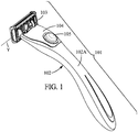
- Figure 1 illustrates a shaving razor 101 according to the first embodiment of the invention, comprising a handle 102, a razor cartridge 103, a cover 104 and an actuation button 105.
- the handle 102 may be elongated, comprising an elongated handle body 102A.
- the handle body 102A may include a gripping portion.
- the handle body 102A may be further made of low-cost material, such as plastic material.
- the handle body 102A may be manufactured from any other suitable material, such as metal.
- the handle body 102A according to the present invention may comprise as little components as possible.
- the handle body 102A may be made as one piece.
- the handle body 102, the cover 104 and/or the button 105 may comprise at least one finger rest area.
- the finger rest areas may be manufactured for instance from rubber or the like.
- the shaving razor 101 is adapted for use with disposable razor cartridges.
- the shaving razor 101 may be provided with arm assembly comprising two arms 106, as can be seen on Figure 2 .
- the arms 106 are adapted to engage and disengage the razor cartridge 103.
- the two arms 106 may be movable between a rest position, in which the cartridge 103 is attached to the handle 102, and a release position, in which the two arms 106 come closer together, thereby releasing the razor cartridge 103 from the handle 102.
- the cartridge 103 may be provided with a pair of rims 103A.
- the rims 103A may be adapted to engage with a pair of shell bearings 119A provided on the arms 106.
- the shell bearings 119A and the rims 103A are preferably adapted to support pivotal movement of the cartridge 103 around the Y-axis.
- the arms 106 may be compatible with an intermediate structure attached to the cartridge 103. The arms 106 then might engage and disengage with the intermediate structure, or both the cartridge 103 and an intermediate structure.
- an elastic return force is applied to the two arms 106, so that the arms 106 are elastically biased towards the rest position.
- the elastic return force may be represented by an elastic member 107 interconnecting the arms 106. The elastic member 107 pushes both arms 106 away from each other, thus returning them both to the rest position.
- more than one elastic component may be incorporated in the handle 102, each elastic component applying return force to at least one of the arms 106.
- the actuation button 105 shown on Figures 1-4 of the accompanying drawings is movably mounted on the handle body 102A.
- the actuation button 105 is adapted to be movable between a lifted position and a depressed position.
- the actuation button 105 cooperates by means of the camming action with the pair of arms 106, such that upon actuation of the actuation button 105 into the depressed position, the arms 106 are moved closer together into the release position, thus disengaging from the cartridge 103.
- the pair of arms 106 is elastically biased into the rest position, and simultaneously by means of the camming action, the pair of arms 106 force the actuation button 105 back into the lifted position.
- the lock and release mechanism will be provided below.
- the actuation button 105 may comprise a substantially spherical part.
- the substantially spherical part may constitute any portion of a sphere, for instance a half-sphere.
- the substantially spherical part is visible for a user.
- the actuation button 105 itself may have substantially spherical shape as shown on Figures 1-4 .
- the substantially spherical actuation button 105 may be manufactured so that it adds weight to the distal part of the handle 102. With a substantially spherical actuation button 105, the manufacturing process of the actuation button 105, as well as the whole lock and release mechanism is simplified, which makes the shaver assembly less costly.
- the substantially spherical actuation button 105 is that the sphere is symmetrical and easy to mold.
- the symmetric shape also simplifies the whole manufacturing process, since there is no directional dependency, when placing the sphere in the handle body 102A during an assembly of the handle 102.
- the substantially spherical shape of the actuation button 105 is also comfortable for a user when using the button 105 as a finger rest area.
- the two arms 106 extend substantially in a common plane XY.
- the button 105 is mounted in the handle body 102A, so that it can move in a direction substantially perpendicular to the plane XY.
- the button 105 is preferably restricted in motion within the plane XY by being fixed inside the hole 127 of the cover 104.
- the button 105 is restricted in movement to the sides of the handle 102 and along the longitudinal direction of the handle 102.
- the restriction in movement of the button 105 along the longitudinal direction of the handle 102 inside the handle 102 is ensured by blocking protrusions 113.
- the button 105 is preferably restricted from rotational movement.
- the restriction in rotational movement can be achieved for example by covering the surface of the button 105 with a suitable material, such as rubber or other elastomeric materials, increasing the friction between the button 105 and the rim of the hole 127.
- a suitable material such as rubber or other elastomeric materials
- the rubber or other elastomeric material may also serve as suitable finger rest area.
- the actuation button 105 may thus also serve as a support area for resting user's finger during shaving. Therefore the actuation button 105 provides support for the user's finger, which is close to the blades, thus the motion of the blades on a user's skin can be led more conveniently during shaving.
- the actuation button 105 may be provided with an outer layer adapted to prevent slipping of a user's finger when the finger is rested against the button 105.
- the button 105 may be manufactured from a material which inherently restricts slippery motion when in contact with user's skin. Examples of such material preventing slippery motion are elastomeric materials, such as rubber or similar.
- the material of the actuation button 105 may have different density from the density of the material of the handle body 102A. Thereby the balance of the handle 102 can be improved.
- the difference between the density of the actuation button 105 and the density of the handle body 102A is at least 10% of the density of the handle body 102A.
- the material of the actuation button 105 may be chosen among materials with density higher than the density of a material used for manufacture of the handle body 102A.
- the button 105 is made of metal.
- the weight of the actuation button 105 helps to improve user's feel during shaving and to enhance shaving performance.
- Such a weight in the distal portion of the handle 102 makes the process of shaving more natural and convenient, especially when the handle body 102A is molded from light low-cost material, such as plastic material.
- the additional weight placed in the button 105 is close to the blades. Therefore the balance of the handle 102 during its use might be improved.
- the additional weight of the actuation button 105 is lower than the elastic return force exerted by the elastic portion, for example the elastic member 107, of the two arms 106. This is so as to avoid unexpected spontaneous release of the cartridge 103 merely by the weight of the button 105 without a user actually pushing the button 105. This provision also ensures that the actuation button 105 can be moved back to the lifted position, when the arms 106 are elastically biased to the rest position.
- FIG 2 shows the lock and release mechanism of the handle 102 according to the first embodiment of the invention.
- the lock and release mechanism comprises two arms 106, the actuation button 105 and an elastic member 107.
- the elastic member 107 comprises a return force generating portion 107A.
- the elastic member 107 further comprises safeguard portions 107B.
- the elastic member 107 is a U-shaped elastic member winding around a guard member 115 as displayed on Figures 2-4 .
- the safeguard portions 107B act as stop members.
- the safeguard portions 107B and the guard member 115 prevent the return force generating portion 107A of the elastic member 107 from reaching the point of the yield or the ultimate tensile stress exerted thereon, the former being the point of maximum stress, that the material can withstand before undergoing permanent plastic deformation, and the latter being the point at which the material breaks.
- the actuation button 105 is pressed into the depressed position, the two arms 106 come closer together, thereby releasing the razor cartridge 103 from the handle 102.
- the safeguard portions 107B are pushed towards each other, so that they rest against the guard member 115.
- Figures 2-4 show the two arms 106 comprising distal parts 119 and proximal parts 117.
- the distal parts 119 of the two arms 106 may be adapted to engage or disengage the razor cartridge 103.
- the distal part 119 of the arms is provided with shell bearings 119A.
- the shell bearings are adapted to fit into the rims 103A provided on the cartridge 103.
- the shell bearings 119A and the rim 103A are preferably adapted to allow pivotal movement of the cartridge 103 around the pivot axis Y. Any alternative means for attaching the pivoting razor cartridge 103 might be used, such as pins and corresponding holes, or the like.
- the pair of arms 106 is pivotally mounted on the handle body 102A with respect to the pivot points.
- the pivot points may be in a form of a pair of pins 111 protruding from the handle body 102A.
- each one of the pins 111 could be fitted into each respective one of a pair of openings 118 provided on the arms 106 as illustrated on Figures 3-4 .
- the openings 118 are preferably provided substantially in the middle of the length of the pivot arms 106.
- the pair of arms 106 is constructed symmetrically with respect to the X-axis. Any alternative solutions enabling relative rotational movement between the handle body 102A and the two arms would also be possible.
- pins may be provided on the pair of arms 106 and the corresponding openings may be disposed in the handle body 102A.
- the proximal parts 117 of the arms 106 there may be a depressed area 120 in the handle body 102A surrounding the proximal parts 117.
- the distal parts 119 of the two arms 106 may be supported by two rest projections 116 protruding from each side of the handle 102. In the rest position the distal parts 119 may lean against the rest projections 116.
- the button 105 When the button 105 is in the depressed position, it is depressed inside the handle body 102A. To this end, there is a cavity 114 hollowed in the handle body 102A as illustrated in Figure 3 . In the cavity 114, the actuation button 105 can be seated conveniently when actuated into the depressed position. As the button 105 is pressed from the lifted position towards the depressed position inside the handle 102, it is lodged into the cavity 114.
- the proximal parts 117 of the arms 106 may each comprise an inclined surface 117A.
- the inclined surfaces 117A are planar.
- the inclined surfaces 117A are preferably facing each other.
- the distal parts 119 move closer together, thereby they release the cartridge 103 from the handle 102.
- the sides of the button 105 adjacent to the inclined surfaces 117A are adapted to slide along the inclined surfaces 117A, as the button 105 is actuated.
- a substantially spherical shape of the button 105 is compatible with inclined surfaces 117A as displayed on Figures 3-4 .
- triangular shape of the portion of the button 105, which contacts the inclined surfaces 117A would be also possible.
- the arms 106 may be adapted so that the distal parts 119 move apart, when the cartridge 103 is being released.
- the proximal parts 117 of the arms may move closer during the release of the cartridge 103.
- the actuation button 105 may be adapted to force the proximal parts 117 together, when the button is actuated.
- the proximal parts 117 may thus alternatively be provided with inclined surfaces 117A with their faces oriented away from each other.
- the actuation button 105 may alternatively comprise a recessed portion, for example of triangular shape, so that when the button 105 is actuated, the recessed portion contacts and slides along the inclined surfaces 117A, thereby forcing them to move closer to each other.
- a set of openings 112 may be provided on the handle 102.
- the openings 112 might engage with a set of corresponding protrusions 124 disposed on the cover 104.
- the cover 104 can preferably be press-fitted in a set of openings 112, in order to be secured to the handle body 102A.
- the cover might be provided with a pair of pockets 122 supposed to cover the pins 111, around which the pair of arms 106 is rotating.
- a pair of posts 125 may be present on the inner side of the cover 104. Each of the pair of posts 125 is preferably fitted between the guard member 115 and one of the arms 106 on the distal-most part of the handle body 102A.
- the hole 127 may also be a hole in the cover 127 abutting the actuation button 105 so that the button 105 is restricted in side-to-side motion.
- the hole 127 has a circular shape.
- the hole 127 has a diameter smaller than the diameter of the button 105.
- the button 105 is retained inside the handle body 102A. Furthermore, the button 105 may partially protrude outside through the hole 127 in the cover 104.
- the cartridge 103 is allowed to pivot around the axis Y.
- the handle 102 is provided with a return means adapted to return the cartridge 103 to a neutral position when the cartridge 103 is rotated.
- the cartridge 103 is held on the handle 102 by shell bearings 119A.
- the shell bearings 119A are adapted to engage with rims 103A provided on the cartridge 103.
- the rims 103A and the shell bearings 119A enable the cartridge 103 to rotate around the axis Y during shaving.
- Other pivoting means which allow the cartridge 103 to pivot around the Y-axis, are also possible, for example pins provided on the arms 106 and the corresponding holes disposed on the cartridge 103.
- the guard member 115 cooperates with stop members 107B in order to prevent the return force generation portion 107A of the elastic member 107 from reaching the point of the the yield or the ultimate tensile stress exerted thereon. Furthermore, the guard member 115 preferably encloses return means for returning the pivoting cartridge 103 to a neutral position. Therefore the guard member 115 serves as a multifunctional element, the number of components included in the lock and release mechanism of the handle 102 is reduced, and the manufacturing process of the handle 102 is simplified.
- the guard member 115 may be molded as a part of the handle body 102A.
- the guard member 115 may be molded in the distal-most part of the handle 102, neighboring the cartridge 103.
- the guard 115 preferably lies on the X-axis of the handle 102.
- the guard member 115 might accommodate any means for returning the cartridge 103 to a neutral position known in the art.
- the return means could be a combination of a pusher 108 and a spring 109.
- the spring 109 may generate the required elastic force for returning the cartridge to a neutral position.
- the pusher 108 preferably cooperates with a corresponding cam surface 110 of the cartridge 103.
- the pusher 108 may be located inside the guard 115.
- the pusher 108 is covered with the cover 104, so that the pusher 108 is restricted in movement in all the directions other than that along the X-axis.
- the pusher 108 is preferably adapted to reciprocate inside the guard 115.
- the pusher 108 may be provided with at least one protrusion 108A.
- the pusher 108 comprises two protrusion 108A provided on the opposite sides of the pusher 108.
- one such protrusion 108A fits inside a groove 115A provided on the inside of the guard 115.
- the cover 104 is also provided with a groove 126, in which the other protrusion 108A is located during movement of the pusher 108.
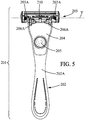
- a shaving razor 201 according to the second embodiment of the invention, comprising a handle 202, a razor cartridge 203, a cover 204 and an actuation button 205.
- the handle 202 may have an elongated handle body 202A, comprising an elongated gripping portion.
- the handle body 202A may be further made of low-cost material, such as plastic material.
- the handle body 202A may be manufactured from any other suitable material, such as metal.
- the handle body 202A according to the present invention comprises as little components as possible.
- the handle body 202A is made as one piece.
- the handle body 202A, the cover 204 and/or the button 205 may comprise at least one finger rest area.
- the finger rest areas may be manufactured for instance from rubber or the like.
- the shaving razor 201 is adapted for use with disposable razor cartridges.
- the shaving razor may be provided with an arm assembly comprising two arms 206 and a connecting portion 214 as can be seen on Figure 6 .
- the arms 206 are adapted to engage and disengage the razor cartridge 203.
- the two arms 206 may be movable between a rest position, in which the cartridge 203 is attached to the handle 202, and a release position, in which the two arms 206 come closer together, thereby releasing the razor cartridge 203 from the handle 202.
- the cartridge 203 may be provided with a pair of rims 203A.
- the rims 203A may be adapted to engage with a pair of shell bearings 206A provided on the arms 206.
- the shell bearings 206A and the rims 203A are preferably adapted to support pivotal movement of the cartridge 203 around the Y-axis.
- the arms 206 may be compatible with an intermediate structure attached to the cartridge 203. The arms 206 then might engage and disengage with the intermediate structure, or both the cartridge 203 and an intermediate structure.
- an elastic return force is applied to the two arms 206, so that the arms 206 are elastically biased towards the rest position.
- the elastic return force may be generated by elastic connections between the pair of arms 206 and a connecting portion 214.
- the pair of arms 206 and the connecting portion 214 may be connected via these elastic connections.
- the pair of arms 206, the elastic connections and the connecting portion 214 may be manufactured as a single piece.
- the pair of arms 206 is made from elastic material.
- the pair of arms 206 may be directly connected to the connecting portion 214, without the presence of elastic connections.
- the elastic return force may be generated by the arms 206 themselves.
- the arms 206 may comprise hinges 207 generating the return force.
- hinges 207 are located at points where the arms 206 protrude from the connecting portion 214, as depicted for example in Figure 6 .
- the connecting portion 214 and the pair of arms 206 extend in the XY plane.
- the arms 206 are movable between the rest position, in which the arm 206 engage the cartridge 203, and the release position, in which the arms 206 disengage the cartridge 203.
- the hinges 207 may be adapted to generate an elastic return force. When the two arms 206 are in the release position, the hinges 207 push both arms 206 away from each other, thus returning them back to the rest position.
- the actuation button 205 shown on Figures 5-6 of the accompanying drawings is movably mounted on the handle body 202A.
- the actuation button 205 is adapted to be movable between a lifted position and a depressed position.
- the actuation button 205 cooperates by means of the camming action with the pair of arms 206, such that upon actuation of the actuation button 205 into the depressed position, the arms 206 are moved closer together into the release position.
- the cartridge 203 is thus disengaged.
- the pair of arms 206 is elastically biased into the rest position. Simultaneously, by means of the camming action, the pair of arms 206 forces the actuation button 205 back into the lifted position. More detailed description of the release mechanism is provided below.
- the actuation button 205 may comprise a substantially spherical part.
- the substantially spherical part may constitute any portion of a sphere, for instance a half-sphere.
- the substantially spherical part is visible for a user.
- the actuation button 205 itself may have a substantially spherical shape as shown for instance on Figure 6 .
- the actuation button 205 may be manufactured so that it adds weight to the distal part of the handle 202. With a substantially spherical button 205 the manufacturing process of the actuation button 205, as well as the whole lock and release mechanism, is simplified, which makes the shaver assembly less costly.
- a substantially spherical actuation button 205 is that the sphere is symmetrical and easy to mold. The symmetric shape also simplifies the whole manufacturing process, since there is no directional dependency when placing the sphere in the handle body 202A during an assembly of the handle 202. The substantially spherical actuation button 205 is also comfortable for a user when using the button 205 as a finger rest area.
- the two arms 206 extend substantially in a common plane XY.
- the button 205 is mounted in the handle body 202A, so that it can move in a direction substantially perpendicular to the plane XY.
- the button 205 is preferably restricted in motion within the plane XY by being fixed inside the hole 227 of the cover 204.
- the button 205 is restricted in movement to the sides of the handle 202 and along the longitudinal direction of the handle 202.
- the button 205 may be restricted from rotational movement.
- the restriction in rotational movement can be achieved for example by covering the surface of the button 205 with a suitable material, such as rubber or other elastomeric materials, increasing the friction between the button 205 and the rim of the hole 227.
- the rubber or other elastomeric material may also serve as suitable finger rest area.
- the actuation button 205 may thus also serve as a support area for resting user's finger during shaving. Therefore the actuation button 205 provides support for the user's finger, which is close to the blades, thus the motion of the blades on a user's skin can be led more conveniently during shaving.
- the actuation button 205 may be provided with an outer layer adapted to prevent slipping of a user's finger when rested against the button 205.
- the button 205 may be manufactured from a material which inherently restricts slippery motion when in contact with user's skin. Examples of such material preventing slippery motion are elastomeric materials, such as rubber or similar.
- the material of the actuation button 205 may have different density from the density of the material of the handle body 202A. Thereby the balance of the handle 202 can be improved.
- the difference between the density of the actuation button 205 and the density of the handle body 202A is at least 10% of the density of the handle body 202A.
- the material of the actuation button 205 may be chosen among materials with density higher than the density of a material used for manufacture of the handle body 202A.
- the button 205 is made of metal.
- the weight of the actuation button 205 helps to improve user's feel during shaving and to enhance shaving performance.
- Such a weight in the distal portion of the handle 202 makes the process of shaving more natural and convenient, especially when the handle body 202A is molded from light low-cost material, such as plastic material.
- the additional weight placed in the button 205 is close to the blades. Therefore the perception of the blades on user's skin during the shaving stroke might be enhanced.
- the additional weight of the actuation button 205 is lower than the elastic return force exerted by the elastic portion, for example the hinges 207, of the two arms 206. This is so as to help avoiding unexpected spontaneous release of the cartridge 203 merely by the weight of the button 205 without a user actually pushing the button 205. This provision also ensures that the actuation button 205 can be moved back to the lifted position, when the arms 206 are elastically biased to the rest position.
- connection portion 214 movably mounted on the handle body 202A.
- the connecting portion 214 may be adapted for a sliding motion along the X-axis of the handle 202.
- the connecting portion 214 is adapted to slide in a direction away from the cartridge 203.
- the connecting portion 214 may further include a cavity 214A shaped so that the actuation button 205 fits into the cavity 214A when the actuation button 205 is in the depressed position.
- the actuation button 205 can be seated conveniently when actuated into the depressed position. As the button 205 is pressed from the lifted position towards the depressed position inside the handle 202, it is lodged in the cavity 214A.
- the arms 206 protruding outwardly from the connecting portion 214.
- the arms 206 may protrude in a direction towards the cartridge 203.
- the arms 206 may preferably extend symmetrically to the X-axis. In the rest position the arms 206 may extend such that any portion of the arms 206 located closer to the cartridge 203 is at the same or greater distance from the X-axis than the portion located further from the cartridge 203.
- the arms 206 are diverging from the X-axis.
- the pair of arms 206 and the connecting portion 214 lie in the XY plane.
- the cartridge 203 is allowed to pivot around an axis Y.
- the handle 202 is provided with return means adapted to return the cartridge 203 to a neutral position when the cartridge 203 is rotated.
- the cartridge 203 is held on the handle 202 by shell bearings 206A.
- the shell bearings 206A are adapted to engage with rims 203A provided on the cartridge 203.
- the rims 203A and the shell bearings 206A enable the cartridge 203 to rotate around the axis Y during shaving.
- Other pivoting means which allow the cartridge 203 to pivot around the Y-axis, are also possible, for example pins provided on the arms 206 and the corresponding holes disposed on the cartridge 203.
- each of the two arms 206 may be supported by a respective rest projection 216 protruding from each side of the handle 202. In the rest position the arms 206 lean against the rest projections 216.
- At least one inclined surface 217 may be provided on the connecting portion 214.
- the at least one inclined surface 217 is located near the edge of the connecting portion 214.
- the at least one inclined surface 217 may be planar.
- the at least one inclined surface may protrude outside from the connecting portion 214 in a direction perpendicular to the XY plane.
- the at least one inclined surface 217 protrudes from the connecting portion 214, so that the inclined surface 217 is in contact with the actuation button 205.
- the button 205 In the lifted position, the button 205 is seated between the cover 204 and the at least one inclined surface 217.
- the at least one portion of the actuation button 205, which contacts the at least one inclined surface 217 of the connecting portion 214 may be adapted to slide along the at least one inclined surface 217 during the actuation of the button 205.
- a substantially spherical shape of the button 205 is compatible with the at least one inclined surface 217 as displayed on Figure 6 .
- triangular shape of the at least one portion of the button 205, which contacts the at least one inclined surface 217 would be also possible.
- the handle 202 may be provided with push features 229.
- the push features 229 may project from the rest projections 216 towards the center part of the handle 202, in a direction parallel to the Y-axis.
- the arms 206 may lean against the push features 229.
- the push features 229 contact the arms 206 substantially in the middle of the length of the arms 206.
- the push features 229 preferably contact that side of the arms 206, which is further from the X-axis.
- the actuation button 205 When the actuation button 205 is pressed by the user towards the depressed position, it may slide along the at least one inclined surface 217 of the connecting portion 214. As the button 205 slides along the at least one inclined surface 217, the connecting portion 214 is forced by the button 205 to slide along the X-axis. For example, the connecting portion 214 is pushed along the X-axis in a direction away from the cartridge 203 during the actuation of the button 205. Preferably, the connecting portion 214 slides within inside of the depressed area 220.
- the connecting portion 214 may be attached to the pair of arms 206 by a pair of elastic connections.
- the connecting portion 214 and the arm 206 slide together along the X-axis.
- the connecting portion 214 and the arms 206 slide in a direction away from the cartridge 203.
- the push features 229 may be adapted to move the arms 206 closer together, when the arms 206 and the connecting portion 214 slide together along the X-axis.
- the push features 229 may thus force the arms 206 from the rest position to the release position, thereby disengaging the arms 206 from the cartridge 203.
- the arms 206 in the rest position the arms 206 may extend such that any portion of the arms 206 located closer to the cartridge 203 is at the same or greater distance from the X-axis, than the portion located further from the cartridge 203.
- the push features 229 are located substantially in the middle of the length of the arms 206.
- any portion of the arms 206 closer to the cartridge 203 than the push features 229 is also more distant from the X-axis, when compared to the push features 229.
- the corresponding portions of the arms 206 are forced closer together by the push features 229.
- the push features 229 force the arms 206 into the release position, and the cartridge 203 is released.
- the motion of the actuation button 205 from the lifted position into the depressed position is connected with the movement of the arms 206 from the rest position into the release position.
- the arms 206 may move close to each other, towards the release position, thereby releasing the cartridge 203 from the handle 202.
- the two arms 206 are elastically biased towards the rest position by an elastic force generated by the hinges 207.
- the elastic force generated by the hinges 207 may lift the actuation button 205 back to the lifted position, when the button 206 is released by a user.
- the handle 202 may include a spring 242 positioned near the proximal side of the connecting portion 214. More particularly, the spring 242 may be located between the proximal side of the connecting portion 214 and a corresponding adjacent wall of the depressed area 220. The spring 242 may be partially embedded into the proximal wall of the depressed area 220 neighboring the proximal side of the connecting portion 214. As the connecting portion 214 is slid away from the cartridge 203 during actuation of the actuation button 205, the connection portion presses the spring 242 against the proximal wall of the depressed area 220, thereby increasing the elastic tension within the spring 242. Therefore, the spring 242 may further support the return force generated by the hinges 207, when the actuation button 205 is about to be raised into the lifted position.
- the pair of arm 206 may be closer together in the rest position than in the release position. For example, when the actuation button 205 is actuated the arms 206 are forced apart into the release position, thus the cartridge 203 is released.
- a guard member 215 may be provided on the handle body 202A.
- the guard member 215 may be molded as a part of the handle body 202A.
- the guard member 215 is molded in the distal-most part of the handle 202, neighboring the cartridge 203.
- the guard 215 preferably lies on the X-axis of the handle 202.
- the guard member 215 encloses return means for returning the pivoting cartridge 203 to a neutral position.
- the guard member 215 might accommodate any means for returning the cartridge 203 to a neutral position known in the art.
- the return means could be a combination of a pusher 208 and a spring 209.
- the spring 209 may generate the required elastic force for returning the cartridge 203 to a neutral position.
- the pusher 208 preferably cooperates with a corresponding cam surface 210 of the cartridge 203.
- the pusher 208 may be located inside the guard 215.
- the pusher 208 is covered with the cover 204, so that the pusher 208 is restricted in movement in all the directions other than that along the X-axis.
- the pusher 208 is preferably adapted to reciprocate inside the guard 215.
- the pusher 208 may be provided with at least one protrusion 208A.
- the pusher 208 comprises two protrusions 208A provided on the opposite sides of the pusher 208.
- one such protrusion 208A fits inside a groove 215A provided on the inside of the guard 215.
- the cover 204 is also provided with a groove, in which the other protrusion 208A is located during movement of the pusher 208.
- the arms 206 are provided with stop members 228.
- the stop members 228 ensure that the two arms 206 do not come too close to each other when the arms 206 are moved into the release position.
- the stop members 228 lean against a guard member 215, as the arms 206 are closing towards each other towards the release position.
- the hinges 207 are thus prevented from a sudden overload, which could lead to breaking of the hinges 207.
- the guard member 215 and the stop members 228 prevent the hinges 207 from reaching the point of the yield or the ultimate tensile stress exerted thereon, the former being the point of maximum stress that the material can withstand before undergoing permanent plastic deformation, and the latter being the point at which the material breaks.
- the arms 206 are stopped in the release position, thereby reducing the risk of the hinges 207 stretching too much and reaching the point of the yield or the ultimate tensile stress exerted thereon.
- the functionality and durability of the hinges 207 is improved.
- the probability of accidently breaking the hinges 207 by straining it too much and causing excessive deformation is reduced.
- the hinges 207 are thus less vulnerable to an improper or excessive use, and the reliability of the whole shaver is therefore also improved.
- the protective means such as the guard member 215 and the stop members 228, the lifetime of the shaver might increase; moreover the user's costs spent on shaving are lowered.
- the guard member 215 serves as a multifunctional element. Consequently, the number of components included in the lock and release mechanism of the handle 202 is reduced, and the manufacturing process of the handle 202 is simplified.
- stop features 228 might be adapted so that they do not allow the arms 206 to move into the release position in case the cartridge 203 is pulled out.
- safety features 228A may be disposed on the sides of the distal part of the guard 215.
- the safety features 228A may protrude outwardly from the guard 215 toward the sides of the handle 202.
- the stop features 228 are fastened by the safety features 228A, so that the stop features 228 are prevented from movement toward the cartridge 203. Therefore, the cartridge 203 is more effectively prevented from an accidental release, and the safety of the user is increased.
- the two arms 206, the connecting portion 214 and the stop members 228 are made of plastic material.
- the pair of arms 206 may be directly connected to the connecting portion 214, without the presence of elastic connections.
- the elastic return force may be generated by the arms 206 themselves.
- the arms 206 may comprise the hinges 207 generating the return force.
- a set of openings 212 may be provided on the handle 202.
- the openings 212 might engage with a set of corresponding protrusions 224 disposed on the cover 204.
- the cover 204 can preferably be press-fitted in a set of openings 212, in order to be secured to the handle body 202A.
- the hole 227 has a substantially spherical shape
- the hole 227 has a circular shape.
- the hole 227 has a diameter smaller than the diameter of the button 205.
- the button 205 is retained inside the handle body 202A.
- the button 205 may partially protrude outside through the hole 227 in the cover 204.
- a shaver 301 according to another embodiment of the invention is presented on Figure 9 .
- the shaver 301 comprises a handle 302, a cartridge 303, and an actuation button 305.
- the button 305 further comprises a substantially spherical part 305A fixed in the button 305.
- the handle 302 may comprise an elongated handle body 302A, which includes an elongated gripping portion.
- the handle body 302A may be further made of low-cost material, such as plastic material.
- the handle body 302A may be manufactured from any other suitable material, such as from metal.
- the handle body 302A according to the present invention preferably comprises as few components as possible.
- the handle body 302A is made as one piece.
- the handle body 302A and/or the button 305 may comprise at least one finger rest area.
- the finger rest areas may be manufactured for instance from rubber or the like.
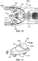
- the distal part of the handle 302 according to the third embodiment of the present invention is illustrated for example in Figure 10 .
- the lock and release mechanism is adapted to releasably engage and disengage the razor cartridge 303.
- the handle 302 is provided with an arm assembly comprising a pair of arms 306.
- the cartridge 303 is pivotally mounted on the pair of arms 306.
- the arms 306 are movable between the rest position, when the cartridge 303 is engaged on the handle 302, and the release position when the cartridge 303 is disengaged from the handle 302.
- the arms 306 are provided with shell bearings 306A by means of which the cartridge 303 is mounted on the handle 302. In the rest position the shell bearings 306A are engaged with rims 303A provided on the cartridge 303.
- the rims 303A and the shell bearings 306A enable a rotational movement of the cartridge 303 around the pivot axis Y.
- Any alternative means for attaching the pivoting razor cartridge 303 might be used, such as pins and corresponding holes, or the like.
- the arms 306 may be compatible with an intermediate structure attached to the cartridge 303.
- the arms 306 then might engage and disengage with the intermediate structure, or both the cartridge 303 and an intermediate structure.
- the pair of arms 306 is adapted to cooperate with the actuation button 305.
- the two arms 306 are moved closer together into the release position by way of camming action between the actuation button 305 and the pair of arms 306.
- the actuation button 305 may comprise a substantially spherical part 305A.
- the substantially spherical part 305A may constitute any portion of a sphere, for instance a half-sphere.
- the substantially spherical part 305A is visible for a user.
- the substantially spherical part 305A is preferably positioned so that the user's finger comes in contact therewith when actuating the button 305.
- the manufacturing process of the substantially spherical part 305A is simpler quicker and with less production costs than the manufacturing process of other more complex parts.
- the substantially spherical shape is also comfortable for a user when using the substantially spherical part 305A as a finger rest area.
- the material of the substantially spherical part 305A may have different density from the density of the material of the handle body 302A. Thereby the balance of the handle 302 can be improved.
- the difference between the density of the substantially spherical part 305A and the density of the handle body 302A is at least 10% of the density of the handle body 302A.
- the substantially spherical part 305A might be manufactured so that it adds weight to the distal part of the handle 302. More particularly, the substantially spherical part 305A may be manufacutured from material with density higher than the density of the material used for manufacturing handle body 302A. For example, the substantially spherical part 305A may be made of metal.
- the actuation button 305 can thus serve multiple functions. It releases the razor cartridge 303. It also provides additional weight to the distal part of the handle 302.
- the substantially spherical part 305A of the actuation button 305 provided with additional weight helps to improve user's feel during shaving and to enhance shaving performance.
- the additional weight in the distal portion of the handle 302 makes the process of shaving more natural and convenient, especially when the handle body 302A is molded from light low-cost material, such as plastic material.
- the additional weight placed in the button 305 is close to the blades. Therefore the perception of the blades on user's skin during the shaving stroke might be enhanced.
- the actuation button 305 and/or the substantially spherical part 305A of the actuation button 305 may serve as a support area for resting user's finger. Therefore, the button 305 and/or the substantially spherical part 305A of the button 305 may be coated with rubber or other elastomeric material to prevent slipping of a user's finger when the finger is rested against the button 305. Alternatively, the button 305 may be manufactured from a material which inherently restricts slippery motion when in contact with user's skin. Examples of such material preventing slippery motion are elastomeric materials, such as rubber or similar.
- each arm 306 comprises a receptacle 330.
- the receptacles 330 are provided on the front surface of each respective arm 306.
- the receptacles 330 may be of non-linear shape.
- the receptacles 330 may be of a substantially beam-like shape.
- the receptacles 330 are adapted to receive pins 337 provided on the button 305.
- the arms 306 are positioned symmetrically with respect to the X-axis on the handle 302.
- a platform 331 is positioned between the arms 306, a platform 331 is positioned.
- the platform serves multiple purposes. It provides a support for the pusher 308. Further, it locks the button 305 in its position and helps to prevent disengagement of the button 305.
- the platform 331 preferably takes an overall shape of a prism. Preferably, the walls of the platform 331 that are adjacent to the arms 306 are parallel to the longitudinal axis of the shaver.
- the platform 331 comprises a front wall, the front wall being oriented towards the button 305.
- the front wall of the platform comprises a track 331A.
- the track 331A is adapted to receive one of the guiding protrusions 308A provided on the pusher 308.
- the track 331A then helps to guide the pusher 308 to reciprocate linearly, reducing risk of the pusher 308 being displaced or misguided in a wrong direction. Therefore, the risk of damage of the pusher 308 is lowered, and the function of the cartridge 303 returning to its rest position is enhanced.
- the arms 306 and the platform 331 are separated from each other by non-linear slots 332.
- the non-linear slots 332 are provided between the platform 331 and each respective arm 306.
- Each of the non-linear slots 332 comprises a portion defining a linear part 333.
- the linear part 333 is adapted to cooperate with the button 305, namely with locators 338 provided on the portion of the button 305 that mates with distal part of the handle body 302A.
- the slot is of substantially rectangular shape.
- the slot 334 may be elongated in one direction. Preferably, this direction is parallel to the longitudinal axis of the shaver 301.
- the walls of the slot 334 parallel to the longitudinal axis of the shaver 301 are parallel to each other, and also to the side walls of the platform 331.
- the side walls of the slot 334 may be provided substantially in one line with the side walls of the platform 331.
- the side walls form two longitudinal edges forming a pair of opposed tracks.
- the tracks are adapted to receive flexible hooks 339 of the button 305.
- the proximal wall of the slot 334 may comprise a stop projection 335.
- the stop projection 335 protrudes into the slot 334.
- the front wall of the stop projection 335 is aligned with the front wall of the platform 331. In this way, the stop projection 334 does not interfere with the possible movements of the pusher 308.
- the stop projection 335 prevents flexible hooks 339 of the button 305 from being brought either closer together, or, in an alternative embodiment, further apart. The stop projection 335 thus helps to prevent the disengagement of the button 305, and disassembly of the handle 302, when the handle 302 is dropped or exposed to shock.
- the front portion of the distal part of the handle body 302A is adapted to receive the release button 305.
- the button 305 is preferably formed as a body with a protruding part 340.
- the protruding part 340 protrudes from the far side of the button 305 with respect to the distal front portion of the handle body 302A, and away from the handle body 302A.
- the protruding part is adapted to accommodate the substantially spherical part 305A.
- the substantially spherical part 305A is adapted to contact the user's finger, when the button 305 is being actuated.
- the protruding part may be provided with a finger rest portion 340A.
- the finger rest portion 340A prevents slipping motion between the button 305 and the user's finger as the button 305 is actuated by the user, therefore enabling a smooth control of the release mechanism.
- the finger rest portion 340A is preferably made from suitable elastomeric material, such as rubber, silicone or the like.
- the outer surface of the substantially spherical part 305A may also be provided with a finger rest portion.
- the substantially spherical part 305A may be coated with suitable elastomeric material such as rubber.
- the back portion of the button 305 which can be seen in Figure 14 , comprises a pair of lockers 338.
- the lockers 338 protrude outward from the side of the button 305 which engages with the handle body 302A.
- the lockers 338 are preferably positioned on a side of the button 305 closer to the cartridge 303, i.e. on the distal-most part of the button 305.
- the lockers are positioned symmetrically with respect to the longitudinal axis of the shaver 301.
- the lockers 338 are offset so as to enable the platform 331 to be positioned between them. This prevents the lockers 338 to be accidentally brought closer together, and thus damaged or disengaged from the handle body 302A.
- the platform 331 and the lockers 338 define an opening through which the pusher 308 protrudes.
- the pusher 308 is configured to reciprocate in this opening.
- One of the protrusions 308A provided on the pusher 308 engages with the track 331A of the platform 331. Similar track to the one present on the platform 331 may be provided also on the side of the button 305 which engages the handle body 302A. As a result, the pusher 308 is provided guidance so that the function of the pusher 308 is secured.
- the pusher 308 cooperates with a spring 309.
- the cooperation of these two components provides a return means for returning the pivoting cartridge 303 to a neutral position when the cartridge 303 is in use and rotated.
- the spring 309 may also provide a pushing force for pushing the cartridge 303 away from the shell bearings 306A after the cartridge 303 is disengaged from the handle 302.
- Each of the lockers 338 is provided in a form of an outwardly oriented hook. When the button 305 is in the rest position, the lockers 338 engage the linear part 333 of the non-linear slot 332.
- the inner portion of the button 305 which is in contact with the handle body 302A, comprises a pair of pins 337.
- the pins 337 are preferably positioned so as to engage the receptacles 330, provided in the arms 306.
- the receptacles 330 may be in a form of grooves, which can be non-rectilinear and may be oriented slantwise, outwardly forwardly.
- the pins provide means for moving the arms 306 closer together when the cartridge 303 is to be disengaged.
- the button 305 When the button 305 is actuated by the user, it slides along the longitudinal direction of the handle 302 towards the cartridge 303.
- the pins 337 move forward in the receptacles 330, thus forcing the arms 306 to flex and move closer together.
- Each shell bearing 306A thus disengage from the corresponding rim 303A of the cartridge 303.
- the cartridge 303 may be urged away from the shell bearing 306A by the pusher 308. Therefore the cartridge 303 is removed from the handle 302 and can be replaced with a new one.
- the inner portion of the button 305 further comprises flexible hooks 339.
- the flexible hooks 339 are preferably provided near the proximal end of the button 305, i.e. on the end more distant from the cartridge 303.
- the flexible hooks 339 protrude outwardly from that side of the button 305 which engages with the handle body 302A. When the lock and release mechanism is assembled, they extend through the slot 334 provided next to the platform 331.
- the flexible hooks 339 take an overall shape of a hook, with the bent portion being positioned on the distant portion of the flexible hooks 339.
- the hooks forming the inner part of the flexible hooks 339 are outwardly oriented, i.e. bent outward.
- the flexible hooks are preferably opposed.
- the flexible hooks engage the side walls of the slot 334.
- the hooks are then held by the end of the side walls of the slot 334.
- the flexible hooks 339 are snap-fitted with the tracks.
- the shaver 401 of the fourth embodiment of the invention comprises a handle 402, a cartridge 403, and an actuation button 405.
- the handle 402 comprises a handle body 402A, which may serve as a gripping area.
- the handle body 402A may be further made of low-cost material, such as plastic material.
- the handle body 402A may be manufactured from any other suitable material, such as metal.
- the handle body 402A preferably comprises as little components as possible.
- the handle body 402A is made as one piece.
- the the handle body 402A and/or the button body 405B and/or the substantially spherical part 405A may comprise at least one finger rest area.
- the finger rest areas may be manufactured for instance from rubber or the like.
- the handle body 402A may be elongated, comprising an elongated gripping portion.
- the actuation button 405 furhter comprises a button body 405B and a substantially spherical part 405A.
- the substantially spherical part 405A may be located substantially in the middle of the button body 405B.
- the button body 405B and the substantially spherical part 405A may be manufactured as two separate pieces.
- the button body 405B may be mounted on the handle body 402A so that the button body 405B slides substantially along the longitudinal direction of the handle 402.
- the button body 405B is preferably slidably mounted on the handle body 402 along the X-axis between a first position and a second position. In the first position, the button body 405B is at the furthest point from the cartridge 403. In the second position, the button body 405B is at closest point to the cartridge 403.
- the substantially spherical part 405A may be movable within the button body 405B.
- the substantially spherical part 405A is mounted on the handle body 402, so that it can move in a direction substantially perpendicular to the plane XY.
- the substantially spherical part 405A may be movable between a lifted position, when the substantially spherical part 405A partially protrudes outside the button body 405B, and a depressed position when the substantially spherical part 405A is fully depressed in the inside of the button body 405B.
- the material of the substantially spherical part 405A may have different density from the density of the material of the handle body 402A. Thereby the balance of the handle 402 can be improved.
- the difference between the density of the substantially spherical part 405A and the density of the handle body 402A is at least 10% of the density of the handle body 402A.
- the substantially spherical part 405A of the button 405 may be manufactured so that it adds weight to the distal part of the handle 402. Therefore, the substantially spherical part 405A may be made of material with density higher than the density of material used for manufacturing the handle body 402. Such additional weight of the substantially spherical part 405A helps to improve user's feel during shaving and to enhance shaving performance.
- the additional weight in the distal portion of the handle 402 makes the process of shaving more natural and convenient, especially when the handle body 402A is molded from light low-cost material, such as plastic material.
- the additional weight placed in the button body 405B is close to the blades. Therefore the perception of the blades on user's skin during the shaving stroke might be enhanced.
- the substantially spherical part 405A could be made from metal. Alternatively, the substantially spherical part 405A might be made from metallic alloy.
- the substantially spherical part 405A may prevent the button body 405B from sliding along the longitudinal direction of the handle 402, when the substantially spherical part 405A is in the lifted position.
- the substantially spherical part can lock the button body 405B in the first position.
- the substantially spherical part cooperates with the button body 405B so as to enable the botton body 405B to slide toward the second position, when the substantially spherical part 405A is in the depressed position.
- the advantage of the button body 405B being locked in the first position, while the substantially spherical part 405A is in the lifted position, is the possibility to use the button body 405B as a finger rest area even more comfortably during shaving.
- the user is advantageously allowed to place his finger in a close proximity to the blades, so that he/she can lead the shaving blades more effectively.
- the only way to disengage the cartridge 403 from the handle 402 is to unlock the button body 405B by pressing the substantially spherical part 405A in a direction substantially perpendicular to the XY plane.
- the advantage of such configuration is that the user can apply almost any force desirable when resting his/her on the actuation button 405 in a direction of X-axis, when pushing the shaver 401 towards his/her skin. Therefore, by locking the button body 405B in a first position, the user's safety is even further increased.
- the actuation button 405 may provide support for the user's finger, which is close to the blades, thus the motion of the blades on a user's skin can be led more conveniently during shaving.
- the substantially spherical part 405A can thus serve multiple functions. It might operate as a locking mechanism with respect to the sliding of the button body 405B. It may also provide additional weight to the distal part of the handle 402.
- the substantially spherical part 405A could be a sphere.
- the spherical shape provides directional independence and allows for arbitrary placement in the handle body 402A during the manufacturing process.
- the manufacturing process of the substantially spherical part 405A may thus be simpler, quicker and with less production costs then the manufactuting process of other more complex parts.
- the spherical shape is also comfortable for a user when using the substantially spherical part 405A as a finger rest area.
- the button body 405B and/or the substantially spherical part 405A in the lifted position may serve as a support area for resting user's finger, for example during shaving. Therefore, the button body 405B and/or the substantially spherical part 405A may be coated with rubber or other elastomeric material to prevent slipping of a user's finger when the finger is rested against the button body 405B and/or the substantially spherical part 405A. Alternatively, the button body 405B and/or the substantially spherical part 405A may be manufactured from a material which inherently restricts slippery motion when in contact with user's skin. Examples of such material preventing slippery motion are elastomeric materials, such as rubber or similar.
- the button body 405B may be provided with an extended portion 444.
- the extended portion 444 may enlarge the area, which might serve for resting user's finger. With the extended portion 444, placing of the user's finger on the surface of the button body 405B may become more comfortable for the user.
- the extended portion 444 is covered with a suitable elastomeric material, such as rubber or the like.
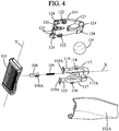
- the distal part of the handle 402 according to the fourth embodiment of the present invention is illustrated in Figures 16-19 .
- the lock and release mechanism is adapted to releasably engage and disengage a razor cartridge 403.
- the handle 402 is provided with an arm assembly comprising a pair of arms 406.
- the arms 406 are positioned symmetrically with respect to the X-axis on the handle body 402A.
- the cartridge 403 may be pivotally mounted on the pair of arms 406.
- the arms 406 may be flexible.
- the arms 406 may be manufactured from any suitable elastic material, such as plastic.
- the arms 406 are molded integrally with the handle body 402A.
- the arms 406 are movable between the rest position, when the cartridge 403 is engaged on the handle 402, and the release position when the cartridge 403 is disengaged from the handle 402. Upon moving from the rest position toward the release position during the release of the cartridge 403, the arms 406 may move closer to each other. Alternative embodiment, where the arms 406 move further apart during the disengagement of the cartridge 403, would be also possible.
- the arms 406 When the arms 406 are moved closer together towards the release position, the arms 406 may generate an elastic return force, which forces the arms 406 back into the rest position.
- the arms 406 may thus be elastically biased toward the rest position, when the button 405 is actuated. After the button 405 is released by the user, it may be pushed back into the first position by the biasing force generated by the pair of arms 406.
- the arms 406 and the corresponding features of the button 405 may be constructed for example as described in WO2010/037418A1 .
- the arms 406 may be provided with shell bearings 406A by means of which the cartridge 403 is mounted on the handle 402. For example, in the rest position the shell bearings 406A are engaged with corresponding rims (not shown) provided on the cartridge 403. The rims and the shell bearings 406A enable a pivotal movement of the cartridge 403 around the pivot axis Y. Any alternative means for attaching the pivoting razor cartridge 403 might be used, such as pins and corresponding holes, or the like.
- the arms 406 may be compatible with an intermediate structure attached to the cartridge 403. The arms 406 then might engage and disengage with the intermediate structure, or both the cartridge 403 and an intermediate structure.
- the pair of arms 406 is adapted to cooperate with the actuation button 405. Upon actuation of the actuation button 405 the two arms 406 are moved closer together by way of camming action between the actuation button 405 and the pair of arms 406. As the button body 405B is slid forward along the X-axis from the first position to the second position toward the shaver's cartridge 403, the pair of arms 406 move closer together from the rest position towards the release position.
- Each arm 406 comprises a receptacle 430.
- the receptacles 430 are provided on the front surface of each respective arm 406.
- the receptacles 430 may be of non-linear shape.
- the receptacles 430 may be of a substantially bean-like shape.
- the receptacles 430 are preferably leaning away from one another from proximal to the distal part of the handle 402 with respect to the longitudinal direction given by the X-axis.
- the receptacles 430 may be in a form of grooves, which can be non-rectilinear and may be oriented slantwise, outwardly forwardly.
- the receptacles 430 are adapted to receive pins 437 provided on the button body 405B.
- the receptacles are preferably configured such that when the button body 405B moves forward into the second position, the arms 406 tend to move closer to each other, whereas when the button 405 returns back in its first position, the pair of arms 406 deviates back apart.
- the lower portion of the button body 405B comprises a pair of pins 437.
- the pins 437 provide means for moving the arms 406 closer together when the cartridge 403 is to be disengaged.
- the pins 437 are preferably positioned so as to engage the receptacles 430, provided in the arms 406. The cartridge 403 may thus be disengaged from the shell bearings 406A and removed or replaced.
- the pins 437 engage the receptacles 430 to drive the arms 406.
- the pins 437 drive the receptacles 430 to flex the arms 406 when the button body 405B is pushed from the first into the second position.
- the button body 405B slides along the X-axis towards the cartridge 403.
- the pins 437 move forward in the receptacles 430, thus forcing the arms 406 to flex and move closer together.
- Each shell bearing 406A thus disengage from the cartridge 403. Therefore the cartridge 403 is removed from the handle 402 and can be replaced with a new one.
- an elastic tongue 445 may be positioned between the arms 406, an elastic tongue 445 may be positioned.
- the elastic tongue 445 may return the cartridge 403 to a neutral position, when the cartridge 403 pivots around the Y-axis.
- the elastic tongue 445 is located on or parallel to the X-axis.
- the elastic tongue 445 may be replaced by any other return force generating means, such as plunger or the like.
- the button body 405B may have a cavity 414, which is open toward the handle body 402A.
- the substantialy spherical part 405A is located substantially inside the cavity 414.
- the cavity 414 may be dimensioned so that the substantially spherical part 405A can enter entirely in the cavity 414, as the substantially spherical part 405A is in the depressed position.
- the button body 405B may further include a cover 404 partially covering the cavity 414 opposite to the handle body 402A. In the lifted position the substantially spherical part 405A may partially protrude upwardly outside the button body 405B through a through hole 427.
- the through hole 427 is disposed in the cover 404 of the button body 405B.
- the through hole 427 is adapted to prevent the substantially spherical part 405A from escaping the cavity 414 of the button body 405B.
- the substantially spherical part 405A is preferably restricted from side-to-side movement.
- the through hole 427 may have substantially circular cross section with diameter smaller then the diameter of the substantially spherical part 405A.
- the handle body 402A comprises a guide 443 extending rigidly in the cavity 414 of the button body 405B toward the cover 404.
- the guide 443 may take form of a wall or a post integral with the handle body 402A.
- the substantially spherical part 405A may bear against the guide 443 toward the arm assembly.
- the substantially spherical part 405A bears against the guide all the way from the lifted position to the depressed position, so that the substantially spherical part 405A is guided toward the inside of the button body 405B.
- the substantially spherical part is guide relative to the handle body 402A substantially perpendicular to the longitudinal direction of the handle between the lifted postion and the depressed position.
- the handle body 402 further may comprise a recessed portion 450 hollowed substantially under the cavity 414 of the button body 405B.
- the reccesed portion 450 may be preferably designed to allow at least partial entering of the substantially speherical component 405A, as the substantially spherical part 405A is pressed in the depressed position.
- the recessed portion 450 may be concave, so that the substantially spherical part fits in the recessed portion 450.
- the spring 442 facilitates application of biasing force, which pushes the substantially spherical part 405A back from the depressed position to the lifted position. If no pressure is applied to the substantially spherical part 405A by a user, the force provided by the return spring 442 may keep the substantially spherical part 405A in the lifted postion. Alternatively, the spring 442 may be replaced with a leaf spring or other means providing the return force.
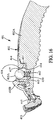
- Figure 16 shows the distal part of the handle 402 with the substantially spheriacal part 405A in the lifted position.
- the button body 405B With the substantially spherical part 405A in the lifte position, the button body 405B is in the first position and the arms 406 are in the rest position.
- the substantially spherical part 405A bears against the guide 443 toward the arm assembly.
- the substantially spherical part is fixed inside the through hole 427 of the cover 404 with respect to the longitudinal direction of the handle. Therefore, in the lifted position the substantially spherical part 405A prevets the button body 405A from sliding.
- the button body 405B is thus locked by the substantially spherical part 405A in the first position.
- the user can initiate movement of the substantially spherical part 405A toward the depressed position.
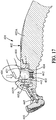
- Figure 17 shows the distal part of the handle 402 with the substantially spherical part 405A in a middle position, which corresponds to the substantially spherical part 405A to be substantially halfway between the lifted position and the depressed position.
- the inclined surface 417 of the button body 405B is enabled to slide along the substantially spherical part 405A. Consequently, the button body 405B is freed to slide to the second position. The user can thus push the button body 405B forward along the X-axis toward the second position.
- the button body 405B starts cooperating with the arms 406, so that the arms 406 start to be flexed closer together toward the release position.
- the substantially spherical part 405A As the button body 405B is slid forward into the second position and the substantially spherical part 405A slides along the inclined surface 417, the substantially spherical part is pressed by the inclined surface 417 of the button body 405B into the depressed position. Since the substantially spherical part 405A bears agains the guide 443, the substantially spherical part 405A cannot move forward in a direction toward the arm assembly, as the substantially spherical part 405A slides along the inclined surface 417.
- Figure 18 shows the distal part of the handle 402 with the substantially spherical part 405A in the depressed position.
- the button body 405B With the substantially spherical part 405A in the depressed position, the button body 405B is in the second position and the arms 406 are in the release position, so that the cartridge 403 can be removed/replaced.
- the substantially spherical part 405A In the depressed position, the substantially spherical part 405A is pressed inside the cavity 414 of the button body 405B. Also the substantially spherical part 405A still bears against the guide 443. For these reasons, the button body 405B cannot slide any further toward the arm assembly.
- the substantaially spherical part enters the recessed portion 450.
- the spring 442 With the substantially spherical part 405A in the depressed position, the spring 442 is fully pressed inside the reccesed portion between the substantially spherical part 405A and the handle body
- the button body 405B can be forced all the way back into the first position by means of the return force generated by the elastic arms 406. Additionaly, by means of the camming action between spring 442, the substantially spherical part 405A and the button body 405B, the return force generated by the spring 442 may contribute to pushing the button body 405B back to the first position. As the substantially spherical part 405A returns to the lifted position, the substantially spherical part 405A is guided along the guide and slides back along the inclined surface 417. Therefore, the substantially spherical part 405A forces the button body 405B back to the first position.
- Figure 21 shows examples of the actuation button 105 of the first embodiment, in all the examples the actuation button 105 comprises two different materials. Nevertheless, the number of materials included in the actuation button 105 could be larger.
- the material of the actuation button 105 may have an average density higher or lower then the density of the material of the handle body 102A.
- the difference between the average density of the actuation button 105 and the density of the material of the handle body 102A is at least 10% of the density of the material of the handle body 102A.
- the actuation button 105 may comprise a plurality of different materials with different densities. Some of these materials could have densities higher than the material of the handle body 102A, and some of these materials could have densities lower than the material of the handle body 102A. Using a combination of multiple materials of the actuation button 105 may have an advantage of both increasing the weight of the handle 102 and providing a gripping and/or rest area for user's finger.
- the weight increasing materials with the density higher than the material of the handle body 102A could be a hight density plastic, metal or other materials.
- the low density materials with the density lower than the material of the handle body 102A could be a light plastic material, rubber or other suitable materials.
- the combination of materials may be selected so that an average density of the plurality of materials is different from the density of the material of the handle body 102A.
- the difference between the average density and the density of the material of the handle body 102A may preferably be at least 10% of the density of the handle body 102A.
- Figure 21a displays a spherical actuation button 105 comprising a material B of density higher than the material of the handle body 102A in the inside of the actuation button 105, and a material A of density lower than the density of the material used to manufacture the handle body 102A on the outside of the actuation button 105. Nevertheless, the reversed arrangement of the materials would also be possible.
- Figure 21b illustrates a material D in the inside of the actuation button 105 and partially protruding to the outside of the actuation button 105.
- the actuation button 105 may include a single material E and a hollow portion F in the inside.
- the hollow portion F thus has density equal to zero or very close to zero.
- Figure 21d shows another example where a material G provided in the center of the spherical actuation button 105 protrudes in various directions towards the outside of the actuaction button 105 through a material H.
- the material H could be a weight increasing material with respect to the handle 102 and the material G could be a material suitable for increasing gripping characteristics of the handle, such as rubber.
- any of the material A, B, C, D, E, G, and H may be selected among materials with the density either lower or higher than the density of the material of the handle body 102A.
Abstract
Description
- The invention relates to wet shaving razors comprising razor handles with release mechanism for engaging and disengaging disposable razor cartridges and method of manufacture such razors.
-
WO2009027910 describes a shaver having a lock & release mechanism operated by an ejector button. The ejector button is mounted on the handle body and comprises a concave area designed for placing user's finger during actuation of a button. - One purpose of the present invention is to improve the shavers of the prior art, in particular with regard to comfort of use and ergonomy.
- The handle for a shaving razor according to the present invention is adapted to releasably support a razor cartridge, said handle comprises an actuation button actuatable to release the razor cartridge. The actuation button comprises a substantially spherical part (i.e. with spherical shape or little deviation from a spherical shape) positioned so that a user's finger comes in contact therewith when actuating the actuation button.
- Thanks to these features, the comfort of use and ergonomy are improved. In particular, the actuation button with its subtantially spherical part, offers more freedom to a user when resting his/her finger on the button both during shaving and / or during actuation of the button.
- Various embodiments of such a handle may incorporate one or more of the following features:
- the handle further comprises a handle body, an arm assembly having two arms provided on the handle body and adapted to engage at least a razor cartridge for supporting it, said arms being movable between a rest position for engaging at least the razor cartridge and a release position for disengaging at least the razor cartridge. The actuation button is movably mounted on the handle body, said actuation button cooperating by camming action with the arm assembly so that the actuation button moves said two arms into the release position when said button is actuated;
- the handle body is made of plastic;
- the substantially spherical part has an average density different from a density of material of the handle body;
- the difference between said average density and said density of the material of the handle body is at least 10%;
- the substantially spherical part comprises at least two different materials with different densities;
- the substantially spherical part has an average density higher than the density of material of the handle body (By this provision the actuation button is multifunctional. The actuation button is adapted to release a razor cartridge from the handle and serves as an additional weight to the handle without a need for additional weight to be disposed on or within the main body of the handle and/or without a need to use inserts fitted therein and/or without a need to increase the plastic volume of the handle or use of special material of higher density during the manufacture of the main gripping portion of the handle. Such actuation button also improves balance of the handle for smooth and comfortable shave)
- the substantially spherical part of the actuation button is made from metal (or the whole button or at least part of the button can be made made of metal);
- the arm assembly is movably mounted on the handle body; the handle body and the arm assembly are separate pieces;
- the actuation button is mounted on the handle body so that it slides substantially along a longitudinal direction of the handle;
- the handle comprises an actuation button movably mounted on the handle body between a lifted position and a depressed position wherein the actuation button is depressed inside the handle body; the actuation button moves said two arms in the release position when the button is pressed to the depressed position; the two arms bias the actuation button toward the lifted position when the actuation button is released;
- the two arms extend substantially in a common plane and the actuation button is mounted on the handle body, so that it can move substantially perpendicular to said common plane;
- the handle comprises at least one elastic portion through which an elastic return force is applied to the two arms when the two arms are moved from the rest position towards the release position; the handle comprises a guard member and a pair of stop members adapted to come into abutment against the guard member when the two arms are in the release position;
- the at least one elastic portion is a U-shaped elastic member interconnecting the two arms; the elastic member is winding around the guard member and comprising a return force generation portion and safeguard portions acting as stop members; the safeguard portions of the U-shaped elastic member come into abutment against the guard member as the two arms are in the release position, e.g. said safeguard portions of the U-shaped elastic member may prevent the return force generating portion of the U-shaped elastic member from reaching the point of the yield or the ultimate tensile stress exerted thereon.
- the two arms have proximal parts closer to the actuation button and distal parts further away from the actuation button, said two arms being pivotable between the rest position and the release position around two pivot points; the proximal parts of the two arms are moved apart during actuation of the actuation button, thereby rotating around the pivot points and resulting in the distal parts of the two arms coming closer together for releasing the razor cartridge from the handle;
- the arm assembly further comprises a connecting portion, the two arms are connected to the connecting portion by hinges and extending from the hinges to respective distal parts adapted to engage with the razor cartridge, the two arms are pivotable between the rest position and the release position around the hinges;
the arm assembly is slideably mounted relative to the handle body along a longitudinal direction of the handle;
the connecting portion comprises an inclined surface with which the actuation button cooperates by earning action when the actuation button is actuated so as to slide the arm assembly in the longitudinal direction,
the arms cooperate by caming action with the handle body so as to be moved to the release position when the arm assembly is slid upon actuation of the actuation button; - the hinges are elastically deformable to allow movement of the arms between the rest position and the release postion;
- the connecting portion includes a cavity in which is received the button ,the inclined surface is formed in a rear portion of said cavity opposed to the distal ends of the arms,
the actuation button is movably mounted in the cavity between a lifted position and a depressed position wherein the actuation button is depressed inside the cavity and presses by caming action on the inclined surface,
the actuation button is guided related to the handle body to move substantially perpendicularly to the longitudinal direction when depressed; - the actuation button is a sphere and is guided in a hole belonging to a cover which covers the arm assembly and which is rigid with the handle body, the hole being dimensioned to avoid the actuation button from escaping the cavity;
- the stop members protrude inwardly towards each other from the two arms and rest against the guard member as the two arms move towards the release position, e.g. preventing the return force generating portions from reaching the point of the yield or the ultimate tensile stress exerted thereon;
- the actuation button is mounted on the handle body so that it slides substantially along a longitudinal direction of the handle;
- the actuation button includes a button body and said substantially spherical part, said button body being mounted on the handle body so that said button body slides substantially along the longitudinal direction of the handle, said substantially spherical part being movably mounted in the button body and being guided relative to the handle body substantially perpendicular to the longitudinal direction of the handle between a lifted position, where the substantially spherical part is lifted outside the button body, and a depressed position where the substantially spherical part is depressed inside the button body, said substantially spherical part being elacstically biased toward the lifted position and cooperating with the button body so as to prevent said button body from sliding when in lifted position and so as to enable said button body to slide when in depressed position;
- the button body has a cavity which is open toward the handle body and a cover partially covering said cavity opposite to the handle body, said cover having a through hole through which the substantially spherical part protrudes outside the cavity when the substantially spherical part is in the lifted position, said handle body having a guide extending in the cavity of the button body toward the cover, the substantially spherical part bearing against said guide toward the arm assembly and said cavity being dimensioned so that the substantially spherical part can enter entirely in said cavity in the depressed position and said substantially spherical part can be at least partially covered by said cover of the button body when the button body is slid toward the arm assembly;
- the handle is adapted to pivotally support a removable razor cartridge, the guard member has return means for returning the razor cartridge to a rest position;
- the substantially spherical part may constitute any portion of a sphere, for instance a half-sphere;
- the subtsantially spherical part may be visible for a user;
- the subtsantially spherical part of the actuation may protrude outwardly from the handle body;
- the subtsantially spherical shape may provide multidirectional support for user's finger, not defining any designated area for a user to rest his finger on (By this provision, the substantially spherical part can serve as a finger rest area offering more freedom for manipulating the shaver both during the shaving and relasing the cartridge by actuating the release button. Moreover, the spherical part increases ergonomic nature of the actuation button);
- the actuation button or at least the substantially spherical part can be adapted to serve as a finger rest area for user's digit during shaving;
- the button itself may have a substantially spherical shape (the sphere is easy to mold with less effort spent on defining complex features of the button, by this provision the manufacturing process is simplified with reduced need for precision during the manufacture of small and delicate components, the symmetric properties of the substantially spherical shape with the directional independency put less demands on precision aspects of the machinery used during the assembly process, the probability of breaking during an accident, e.g. dropping of the shaver, or during a proper constant long-term use of the shaver is decreased, a handle with minimum number of components and less complex features supports the long-term life of the handle and reduces the risk of accidentally breaking the handle or one of its key components).
- Another object of the invention is a shaving razor comprising the handle with any of the above described features and a cartridge mounted on said handle, said cartridge being engaged by the two arms when the two arms are in the rest position and said cartridge being disengaged from the two arms when the two arms are in the release postion, said cartridge being released from said handle upon actuation of the actuation button.
- The above and other objects and advantages of the invention will become apparent from the detailed description of various embodiments of the invention, considered in conjunction with the accompanying drawings.
-
-
Figure 1 is an overall view of the shaving razor according to the first embodiment of the invention. -
Figure 2 is a front view of the distal part of the handle showing the lock & release mechanism according to the first embodiment of the invention. -
Figure 3 shows an exploded view of the distal part of the handle according to the first embodiment of the invention. -
Figure 4 displays an exploded view of the distal part of the handle according to the first embodiment of the invention from another perspective. -
Figure 5 is a front view of the shaving razor according to the second embodiment of the invention. -
Figure 6 shows an exploded view of the distal part of the handle according to the second embodiment of the invention. -
Figure 7a illustrates a side section view of the distal part of the handle before actuation of the button. -
Figure 7b illustrates a side section view of the distal part of the handle after the actuation of the button. -
Figure 8a is another view of the distal part of the handle and the lock & release mechanism before the actuation of the button. -
Figure 8b is yet another view of the distal part of the handle after the actuation of the actuation button. -
Figure 8c shows a variant of the second embodiment, including an additional return spring. -
Figure 9 depicts a shaving razor according to the third embodiment of the invention. -
Figure 10 shows an distal part of the handle without an actuation button according to the third embodiment of the invention. -
Figure 11 displays the main components of an actuation button of the third embodiment. -
Figure 12 is a side section view of the actuation button according to the third embodiment of the invention. -
Figure 13 shows an exploded view of the distal part of the shaving razor according to the third embodiment. -
Figure 14 depicts another exploded view of the distal part of the shaving razor according to the third embodiment from another perspective. -
Figure 15 illustrates a shaving razor according to the fourth embodiment of the invention. -
Figure 16 shows a side section view of the distal part of the shaving razor of the fourth embodiment with a substantially spherical part in the lifted position. -
Figure 17 shows a side section view of the distal part of the shaving razor of the fourth embodiment with a substantially spherical part in the middle position. -
Figure 18 shows a side section view of the distal part of the shaving razor of the fourth embodiment with a substantially spherical part in the depressed position. -
Figure 19 is a front view of the distal part of the handle according to the fourth embodiment. -
Figure 20 is a side view of the actuation button according to the fourth embodiment. -
Figure 21 shows examples of a possible composition of the substantially spherical part of the actuation button. - The following description of the main embodiments of the invention is made with reference to the accompanying drawings, where the same reference numbers denote identical or similar elements.
- In the description, the X-axis represent substantially the longitudinal direction of the handle, whereas the Y-axis is perpendicular to the X-axis; for instance the Y-axis may represent the pivot axis of the razor cartridge.
-
Figure 1 illustrates a shavingrazor 101 according to the first embodiment of the invention, comprising ahandle 102, arazor cartridge 103, acover 104 and anactuation button 105. Thehandle 102 may be elongated, comprising anelongated handle body 102A. Thehandle body 102A may include a gripping portion. Thehandle body 102A may be further made of low-cost material, such as plastic material. Alternatively, thehandle body 102A may be manufactured from any other suitable material, such as metal. Thehandle body 102A according to the present invention may comprise as little components as possible. Thehandle body 102A may be made as one piece. Thehandle body 102, thecover 104 and/or thebutton 105 may comprise at least one finger rest area. The finger rest areas may be manufactured for instance from rubber or the like. - The shaving
razor 101 is adapted for use with disposable razor cartridges. The shavingrazor 101 may be provided with arm assembly comprising twoarms 106, as can be seen onFigure 2 . Thearms 106 are adapted to engage and disengage therazor cartridge 103. For example, the twoarms 106 may be movable between a rest position, in which thecartridge 103 is attached to thehandle 102, and a release position, in which the twoarms 106 come closer together, thereby releasing therazor cartridge 103 from thehandle 102. - The
cartridge 103 may be provided with a pair ofrims 103A. Therims 103A may be adapted to engage with a pair ofshell bearings 119A provided on thearms 106. Theshell bearings 119A and therims 103A are preferably adapted to support pivotal movement of thecartridge 103 around the Y-axis. Alternatively, thearms 106 may be compatible with an intermediate structure attached to thecartridge 103. Thearms 106 then might engage and disengage with the intermediate structure, or both thecartridge 103 and an intermediate structure. - When moving from the rest position towards the release position, an elastic return force is applied to the two
arms 106, so that thearms 106 are elastically biased towards the rest position. In one possible embodiment, the elastic return force may be represented by anelastic member 107 interconnecting thearms 106. Theelastic member 107 pushes botharms 106 away from each other, thus returning them both to the rest position. Alternatively, more than one elastic component may be incorporated in thehandle 102, each elastic component applying return force to at least one of thearms 106. - The
actuation button 105 shown onFigures 1-4 of the accompanying drawings is movably mounted on thehandle body 102A. Theactuation button 105 is adapted to be movable between a lifted position and a depressed position. Theactuation button 105 cooperates by means of the camming action with the pair ofarms 106, such that upon actuation of theactuation button 105 into the depressed position, thearms 106 are moved closer together into the release position, thus disengaging from thecartridge 103. When theactuation button 105 is released by a user, the pair ofarms 106 is elastically biased into the rest position, and simultaneously by means of the camming action, the pair ofarms 106 force theactuation button 105 back into the lifted position. Detailed description of the lock and release mechanism will be provided below. - Advatageously, the
actuation button 105 may comprise a substantially spherical part. The substantially spherical part may constitute any portion of a sphere, for instance a half-sphere. Preferably, the substantially spherical part is visible for a user. Alternatively, theactuation button 105 itself may have substantially spherical shape as shown onFigures 1-4 . The substantiallyspherical actuation button 105 may be manufactured so that it adds weight to the distal part of thehandle 102. With a substantiallyspherical actuation button 105, the manufacturing process of theactuation button 105, as well as the whole lock and release mechanism is simplified, which makes the shaver assembly less costly. One advantage of the substantiallyspherical actuation button 105 is that the sphere is symmetrical and easy to mold. The symmetric shape also simplifies the whole manufacturing process, since there is no directional dependency, when placing the sphere in thehandle body 102A during an assembly of thehandle 102. The substantially spherical shape of theactuation button 105 is also comfortable for a user when using thebutton 105 as a finger rest area. - In a preferred embodiment, the two
arms 106 extend substantially in a common plane XY. Thebutton 105 is mounted in thehandle body 102A, so that it can move in a direction substantially perpendicular to the plane XY. Thebutton 105 is preferably restricted in motion within the plane XY by being fixed inside thehole 127 of thecover 104. Thus thebutton 105 is restricted in movement to the sides of thehandle 102 and along the longitudinal direction of thehandle 102. The restriction in movement of thebutton 105 along the longitudinal direction of thehandle 102 inside thehandle 102 is ensured by blockingprotrusions 113. Additionally, thebutton 105 is preferably restricted from rotational movement. The restriction in rotational movement can be achieved for example by covering the surface of thebutton 105 with a suitable material, such as rubber or other elastomeric materials, increasing the friction between thebutton 105 and the rim of thehole 127. The rubber or other elastomeric material may also serve as suitable finger rest area. Theactuation button 105 may thus also serve as a support area for resting user's finger during shaving. Therefore theactuation button 105 provides support for the user's finger, which is close to the blades, thus the motion of the blades on a user's skin can be led more conveniently during shaving. - In preferred embodiments, the
actuation button 105 may be provided with an outer layer adapted to prevent slipping of a user's finger when the finger is rested against thebutton 105. Alternatively, thebutton 105 may be manufactured from a material which inherently restricts slippery motion when in contact with user's skin. Examples of such material preventing slippery motion are elastomeric materials, such as rubber or similar. - The material of the
actuation button 105 may have different density from the density of the material of thehandle body 102A. Thereby the balance of thehandle 102 can be improved. Preferably, the difference between the density of theactuation button 105 and the density of thehandle body 102A is at least 10% of the density of thehandle body 102A. - The material of the
actuation button 105 may be chosen among materials with density higher than the density of a material used for manufacture of thehandle body 102A. In a possible embodiment, thebutton 105 is made of metal. The weight of theactuation button 105 helps to improve user's feel during shaving and to enhance shaving performance. Such a weight in the distal portion of thehandle 102 makes the process of shaving more natural and convenient, especially when thehandle body 102A is molded from light low-cost material, such as plastic material. The additional weight placed in thebutton 105 is close to the blades. Therefore the balance of thehandle 102 during its use might be improved. - It is taken into consideration that the additional weight of the
actuation button 105 is lower than the elastic return force exerted by the elastic portion, for example theelastic member 107, of the twoarms 106. This is so as to avoid unexpected spontaneous release of thecartridge 103 merely by the weight of thebutton 105 without a user actually pushing thebutton 105. This provision also ensures that theactuation button 105 can be moved back to the lifted position, when thearms 106 are elastically biased to the rest position. -
Figure 2 shows the lock and release mechanism of thehandle 102 according to the first embodiment of the invention. The lock and release mechanism comprises twoarms 106, theactuation button 105 and anelastic member 107. Theelastic member 107 comprises a returnforce generating portion 107A. Theelastic member 107 further comprises safeguardportions 107B. In one embodiment theelastic member 107 is a U-shaped elastic member winding around aguard member 115 as displayed onFigures 2-4 . Thesafeguard portions 107B act as stop members. Thesafeguard portions 107B and theguard member 115 prevent the returnforce generating portion 107A of theelastic member 107 from reaching the point of the yield or the ultimate tensile stress exerted thereon, the former being the point of maximum stress, that the material can withstand before undergoing permanent plastic deformation, and the latter being the point at which the material breaks. When theactuation button 105 is pressed into the depressed position, the twoarms 106 come closer together, thereby releasing therazor cartridge 103 from thehandle 102. At the same time, thesafeguard portions 107B are pushed towards each other, so that they rest against theguard member 115. This prevents thearms 106 from moving further together, thus stopping in the release position and reducing the risk of the returnforce generation portion 107A stretching too much and reaching the point of the yield or the ultimate tensile stress exerted thereon. By such provision the functionality and durability of theelastic member 107 is improved. The probability of accidently breaking theelastic member 107 by straining it too much and causing excessive deformation is reduced. The elastic member is thus less vulnerable to an improper or excessive use, and the reliability of the whole shaver is therefore also improved. With the protective means, such as theguard member 115 and thestop members 107B, the lifetime of the shaver might be increased; moreover the user's costs spent on shaving are lowered. -
Figures 2-4 show the twoarms 106 comprisingdistal parts 119 andproximal parts 117. Thedistal parts 119 of the twoarms 106 may be adapted to engage or disengage therazor cartridge 103. For example, as shown onFigures 2-4 thedistal part 119 of the arms is provided withshell bearings 119A. Preferably, the shell bearings are adapted to fit into therims 103A provided on thecartridge 103. Theshell bearings 119A and therim 103A are preferably adapted to allow pivotal movement of thecartridge 103 around the pivot axis Y. Any alternative means for attaching the pivotingrazor cartridge 103 might be used, such as pins and corresponding holes, or the like. - The pair of
arms 106 is pivotally mounted on thehandle body 102A with respect to the pivot points. The pivot points may be in a form of a pair ofpins 111 protruding from thehandle body 102A. For example each one of thepins 111 could be fitted into each respective one of a pair ofopenings 118 provided on thearms 106 as illustrated onFigures 3-4 . Theopenings 118 are preferably provided substantially in the middle of the length of thepivot arms 106. The pair ofarms 106 is constructed symmetrically with respect to the X-axis. Any alternative solutions enabling relative rotational movement between thehandle body 102A and the two arms would also be possible. For example, pins may be provided on the pair ofarms 106 and the corresponding openings may be disposed in thehandle body 102A. - In order to provide for a smooth movement of the
proximal parts 117 of thearms 106, there may be adepressed area 120 in thehandle body 102A surrounding theproximal parts 117. When returned back to the rest position, thedistal parts 119 of the twoarms 106 may be supported by tworest projections 116 protruding from each side of thehandle 102. In the rest position thedistal parts 119 may lean against therest projections 116. - When the
button 105 is in the depressed position, it is depressed inside thehandle body 102A. To this end, there is acavity 114 hollowed in thehandle body 102A as illustrated inFigure 3 . In thecavity 114, theactuation button 105 can be seated conveniently when actuated into the depressed position. As thebutton 105 is pressed from the lifted position towards the depressed position inside thehandle 102, it is lodged into thecavity 114. - The
proximal parts 117 of thearms 106 may each comprise aninclined surface 117A. For example, theinclined surfaces 117A are planar. Theinclined surfaces 117A are preferably facing each other. When thearms 106 are in the rest position and thebutton 105 is in a lifted position, there are two side portions of thebutton 105, which rest against theinclined surfaces 117A. In the lifted position, thebutton 105 is seated between thecover 104 and theinclined surfaces 117A. During the actuation of thebutton 105, theproximal parts 117 can be moved apart by pressing thebutton 105 between them. As theproximal parts 117 are moved apart, they rotate around thepins 111. Simultaneously, thedistal parts 119 move closer together, thereby they release thecartridge 103 from thehandle 102. The sides of thebutton 105 adjacent to theinclined surfaces 117A are adapted to slide along theinclined surfaces 117A, as thebutton 105 is actuated. For example, a substantially spherical shape of thebutton 105 is compatible withinclined surfaces 117A as displayed onFigures 3-4 . Alternatively, triangular shape of the portion of thebutton 105, which contacts theinclined surfaces 117A, would be also possible. - In an alternative embodiment, the
arms 106 may be adapted so that thedistal parts 119 move apart, when thecartridge 103 is being released. Correspondingly, theproximal parts 117 of the arms may move closer during the release of thecartridge 103. Theactuation button 105 may be adapted to force theproximal parts 117 together, when the button is actuated. Theproximal parts 117 may thus alternatively be provided withinclined surfaces 117A with their faces oriented away from each other. Theactuation button 105 may alternatively comprise a recessed portion, for example of triangular shape, so that when thebutton 105 is actuated, the recessed portion contacts and slides along theinclined surfaces 117A, thereby forcing them to move closer to each other. - As depicted in
Figure 3 , a set ofopenings 112 may be provided on thehandle 102. Theopenings 112 might engage with a set of correspondingprotrusions 124 disposed on thecover 104. Thecover 104 can preferably be press-fitted in a set ofopenings 112, in order to be secured to thehandle body 102A. Additionally, the cover might be provided with a pair ofpockets 122 supposed to cover thepins 111, around which the pair ofarms 106 is rotating. Furthermore, a pair ofposts 125 may be present on the inner side of thecover 104. Each of the pair ofposts 125 is preferably fitted between theguard member 115 and one of thearms 106 on the distal-most part of thehandle body 102A. There may also be a hole in thecover 127 abutting theactuation button 105 so that thebutton 105 is restricted in side-to-side motion. In case theactuation button 105 has a substantially spherical shape, thehole 127 has a circular shape. Preferably, thehole 127 has a diameter smaller than the diameter of thebutton 105. In the preferred embodiment, thebutton 105 is retained inside thehandle body 102A. Furthermore, thebutton 105 may partially protrude outside through thehole 127 in thecover 104. - Preferably, the
cartridge 103 is allowed to pivot around the axis Y. Thehandle 102 is provided with a return means adapted to return thecartridge 103 to a neutral position when thecartridge 103 is rotated. Thecartridge 103 is held on thehandle 102 byshell bearings 119A. Theshell bearings 119A are adapted to engage withrims 103A provided on thecartridge 103. Therims 103A and theshell bearings 119A enable thecartridge 103 to rotate around the axis Y during shaving. Other pivoting means, which allow thecartridge 103 to pivot around the Y-axis, are also possible, for example pins provided on thearms 106 and the corresponding holes disposed on thecartridge 103. - In a preferred embodiment, the
guard member 115 cooperates withstop members 107B in order to prevent the returnforce generation portion 107A of theelastic member 107 from reaching the point of the the yield or the ultimate tensile stress exerted thereon. Furthermore, theguard member 115 preferably encloses return means for returning the pivotingcartridge 103 to a neutral position. Therefore theguard member 115 serves as a multifunctional element, the number of components included in the lock and release mechanism of thehandle 102 is reduced, and the manufacturing process of thehandle 102 is simplified. Theguard member 115 may be molded as a part of thehandle body 102A. Theguard member 115 may be molded in the distal-most part of thehandle 102, neighboring thecartridge 103. Theguard 115 preferably lies on the X-axis of thehandle 102. - The
guard member 115 might accommodate any means for returning thecartridge 103 to a neutral position known in the art. According to the embodiment of the present invention, the return means could be a combination of apusher 108 and aspring 109. Thespring 109 may generate the required elastic force for returning the cartridge to a neutral position. Thepusher 108 preferably cooperates with a correspondingcam surface 110 of thecartridge 103. Thepusher 108 may be located inside theguard 115. Preferably, thepusher 108 is covered with thecover 104, so that thepusher 108 is restricted in movement in all the directions other than that along the X-axis. Thepusher 108 is preferably adapted to reciprocate inside theguard 115. To this end, thepusher 108 may be provided with at least oneprotrusion 108A. For example, thepusher 108 comprises twoprotrusion 108A provided on the opposite sides of thepusher 108. In a preferred embodiment, onesuch protrusion 108A fits inside agroove 115A provided on the inside of theguard 115. Preferably, thecover 104 is also provided with agroove 126, in which theother protrusion 108A is located during movement of thepusher 108. - Illustrated on
Figure 5 is a shavingrazor 201 according to the second embodiment of the invention, comprising ahandle 202, arazor cartridge 203, acover 204 and anactuation button 205. Thehandle 202 may have anelongated handle body 202A, comprising an elongated gripping portion. Thehandle body 202A may be further made of low-cost material, such as plastic material. Alternatively, thehandle body 202A may be manufactured from any other suitable material, such as metal. Thehandle body 202A according to the present invention comprises as little components as possible. Preferably thehandle body 202A is made as one piece. Thehandle body 202A, thecover 204 and/or thebutton 205 may comprise at least one finger rest area. The finger rest areas may be manufactured for instance from rubber or the like. - The shaving
razor 201 is adapted for use with disposable razor cartridges. The shaving razor may be provided with an arm assembly comprising twoarms 206 and a connectingportion 214 as can be seen onFigure 6 . Thearms 206 are adapted to engage and disengage therazor cartridge 203. For example, the twoarms 206 may be movable between a rest position, in which thecartridge 203 is attached to thehandle 202, and a release position, in which the twoarms 206 come closer together, thereby releasing therazor cartridge 203 from thehandle 202. - The
cartridge 203 may be provided with a pair ofrims 203A. Therims 203A may be adapted to engage with a pair ofshell bearings 206A provided on thearms 206. Theshell bearings 206A and therims 203A are preferably adapted to support pivotal movement of thecartridge 203 around the Y-axis. Alternatively, thearms 206 may be compatible with an intermediate structure attached to thecartridge 203. Thearms 206 then might engage and disengage with the intermediate structure, or both thecartridge 203 and an intermediate structure. - When moving from the rest position towards the release position, an elastic return force is applied to the two
arms 206, so that thearms 206 are elastically biased towards the rest position. In one possible embodiment the elastic return force may be generated by elastic connections between the pair ofarms 206 and a connectingportion 214. For example, the pair ofarms 206 and the connectingportion 214 may be connected via these elastic connections. The pair ofarms 206, the elastic connections and the connectingportion 214 may be manufactured as a single piece. In one possible embodiment, the pair ofarms 206 is made from elastic material. The pair ofarms 206 may be directly connected to the connectingportion 214, without the presence of elastic connections. In this case, the elastic return force may be generated by thearms 206 themselves. Thearms 206 may comprise hinges 207 generating the return force. For example, hinges 207 are located at points where thearms 206 protrude from the connectingportion 214, as depicted for example inFigure 6 . Preferably, the connectingportion 214 and the pair ofarms 206 extend in the XY plane. Thearms 206 are movable between the rest position, in which thearm 206 engage thecartridge 203, and the release position, in which thearms 206 disengage thecartridge 203. The hinges 207 may be adapted to generate an elastic return force. When the twoarms 206 are in the release position, thehinges 207 push botharms 206 away from each other, thus returning them back to the rest position. - The
actuation button 205 shown onFigures 5-6 of the accompanying drawings is movably mounted on thehandle body 202A. Theactuation button 205 is adapted to be movable between a lifted position and a depressed position. Theactuation button 205 cooperates by means of the camming action with the pair ofarms 206, such that upon actuation of theactuation button 205 into the depressed position, thearms 206 are moved closer together into the release position. Thecartridge 203 is thus disengaged. When theactuation button 205 is released by the user, the pair ofarms 206 is elastically biased into the rest position. Simultaneously, by means of the camming action, the pair ofarms 206 forces theactuation button 205 back into the lifted position. More detailed description of the release mechanism is provided below. - Advatageously, the
actuation button 205 may comprise a substantially spherical part. The substantially spherical part may constitute any portion of a sphere, for instance a half-sphere. Preferably, the substantially spherical part is visible for a user. Alternatively, theactuation button 205 itself may have a substantially spherical shape as shown for instance onFigure 6 . As one possible aspect of this embodiment, theactuation button 205 may be manufactured so that it adds weight to the distal part of thehandle 202. With a substantiallyspherical button 205 the manufacturing process of theactuation button 205, as well as the whole lock and release mechanism, is simplified, which makes the shaver assembly less costly. One advantage of a substantiallyspherical actuation button 205 is that the sphere is symmetrical and easy to mold. The symmetric shape also simplifies the whole manufacturing process, since there is no directional dependency when placing the sphere in thehandle body 202A during an assembly of thehandle 202. The substantiallyspherical actuation button 205 is also comfortable for a user when using thebutton 205 as a finger rest area. - In a preferred embodiment, the two
arms 206 extend substantially in a common plane XY. Thebutton 205 is mounted in thehandle body 202A, so that it can move in a direction substantially perpendicular to the plane XY. Thebutton 205 is preferably restricted in motion within the plane XY by being fixed inside thehole 227 of thecover 204. Thus thebutton 205 is restricted in movement to the sides of thehandle 202 and along the longitudinal direction of thehandle 202. Additionally, thebutton 205 may be restricted from rotational movement. The restriction in rotational movement can be achieved for example by covering the surface of thebutton 205 with a suitable material, such as rubber or other elastomeric materials, increasing the friction between thebutton 205 and the rim of thehole 227. - The rubber or other elastomeric material may also serve as suitable finger rest area. The
actuation button 205 may thus also serve as a support area for resting user's finger during shaving. Therefore theactuation button 205 provides support for the user's finger, which is close to the blades, thus the motion of the blades on a user's skin can be led more conveniently during shaving. - In preferred embodiments, the
actuation button 205 may be provided with an outer layer adapted to prevent slipping of a user's finger when rested against thebutton 205. Alternatively, thebutton 205 may be manufactured from a material which inherently restricts slippery motion when in contact with user's skin. Examples of such material preventing slippery motion are elastomeric materials, such as rubber or similar. - The material of the
actuation button 205 may have different density from the density of the material of thehandle body 202A. Thereby the balance of thehandle 202 can be improved. Preferably, the difference between the density of theactuation button 205 and the density of thehandle body 202A is at least 10% of the density of thehandle body 202A. - The material of the
actuation button 205 may be chosen among materials with density higher than the density of a material used for manufacture of thehandle body 202A. In a possible embodiment, thebutton 205 is made of metal. The weight of theactuation button 205 helps to improve user's feel during shaving and to enhance shaving performance. Such a weight in the distal portion of thehandle 202 makes the process of shaving more natural and convenient, especially when thehandle body 202A is molded from light low-cost material, such as plastic material. The additional weight placed in thebutton 205 is close to the blades. Therefore the perception of the blades on user's skin during the shaving stroke might be enhanced. - It is taken into consideration that the additional weight of the
actuation button 205 is lower than the elastic return force exerted by the elastic portion, for example thehinges 207, of the twoarms 206. This is so as to help avoiding unexpected spontaneous release of thecartridge 203 merely by the weight of thebutton 205 without a user actually pushing thebutton 205. This provision also ensures that theactuation button 205 can be moved back to the lifted position, when thearms 206 are elastically biased to the rest position. - As one possible aspect of the second embodiment, there is a connecting
portion 214 movably mounted on thehandle body 202A. The connectingportion 214 may be adapted for a sliding motion along the X-axis of thehandle 202. Preferably, the connectingportion 214 is adapted to slide in a direction away from thecartridge 203. - The connecting
portion 214 may further include acavity 214A shaped so that theactuation button 205 fits into thecavity 214A when theactuation button 205 is in the depressed position. In thecavity 214A, theactuation button 205 can be seated conveniently when actuated into the depressed position. As thebutton 205 is pressed from the lifted position towards the depressed position inside thehandle 202, it is lodged in thecavity 214A. - According to another aspect of the second embodiment, there is a pair of
arms 206 protruding outwardly from the connectingportion 214. For example, thearms 206 may protrude in a direction towards thecartridge 203. Thearms 206 may preferably extend symmetrically to the X-axis. In the rest position thearms 206 may extend such that any portion of thearms 206 located closer to thecartridge 203 is at the same or greater distance from the X-axis than the portion located further from thecartridge 203. Thus thearms 206 are diverging from the X-axis. Preferably, the pair ofarms 206 and the connectingportion 214 lie in the XY plane. - Preferably, the
cartridge 203 is allowed to pivot around an axis Y. Thehandle 202 is provided with return means adapted to return thecartridge 203 to a neutral position when thecartridge 203 is rotated. Thecartridge 203 is held on thehandle 202 byshell bearings 206A. Theshell bearings 206A are adapted to engage withrims 203A provided on thecartridge 203. Therims 203A and theshell bearings 206A enable thecartridge 203 to rotate around the axis Y during shaving. Other pivoting means, which allow thecartridge 203 to pivot around the Y-axis, are also possible, for example pins provided on thearms 206 and the corresponding holes disposed on thecartridge 203. - In order to provide for a smooth sliding movement of the connecting
portion 214 along the X-axis, there may be adepressed area 220 in thehandle body 202A surrounding the connectingportion 214. Preferably, thearms 206 are directly connected to the connectingportion 214, so that the connectingportion 214 and thearms 206 slide together. In a preferred embodiment, thearms 206 and the connectingportion 214 are adapted to slide along the X-axis in a direction away from thecartridge 203. When returned back to the rest position, each of the twoarms 206 may be supported by arespective rest projection 216 protruding from each side of thehandle 202. In the rest position thearms 206 lean against therest projections 216. - As another aspect of the second embodiment, at least one
inclined surface 217 may be provided on the connectingportion 214. For example, the at least oneinclined surface 217 is located near the edge of the connectingportion 214. The at least oneinclined surface 217 may be planar. The at least one inclined surface may protrude outside from the connectingportion 214 in a direction perpendicular to the XY plane. Preferably, the at least oneinclined surface 217 protrudes from the connectingportion 214, so that theinclined surface 217 is in contact with theactuation button 205. For example, there is at least one portion on theactuation button 205, which contacts the at least oneinclined surface 217 of the connectingportion 214. In the lifted position, thebutton 205 is seated between thecover 204 and the at least oneinclined surface 217. The at least one portion of theactuation button 205, which contacts the at least oneinclined surface 217 of the connectingportion 214 may be adapted to slide along the at least oneinclined surface 217 during the actuation of thebutton 205. For example, a substantially spherical shape of thebutton 205 is compatible with the at least oneinclined surface 217 as displayed onFigure 6 . Alternatively, triangular shape of the at least one portion of thebutton 205, which contacts the at least oneinclined surface 217, would be also possible. - Additionally, the
handle 202 may be provided with push features 229. For example, the push features 229 may project from therest projections 216 towards the center part of thehandle 202, in a direction parallel to the Y-axis. When thearms 206 are in the rest position, thearms 206 may lean against the push features 229. Preferably, the push features 229 contact thearms 206 substantially in the middle of the length of thearms 206. The push features 229 preferably contact that side of thearms 206, which is further from the X-axis. - When the
actuation button 205 is pressed by the user towards the depressed position, it may slide along the at least oneinclined surface 217 of the connectingportion 214. As thebutton 205 slides along the at least oneinclined surface 217, the connectingportion 214 is forced by thebutton 205 to slide along the X-axis. For example, the connectingportion 214 is pushed along the X-axis in a direction away from thecartridge 203 during the actuation of thebutton 205. Preferably, the connectingportion 214 slides within inside of thedepressed area 220. - The connecting
portion 214 may be attached to the pair ofarms 206 by a pair of elastic connections. In a preferred embodiment, when theactuation button 205 is pressed into the depressed position, the connectingportion 214 and thearm 206 slide together along the X-axis. Preferably, the connectingportion 214 and thearms 206 slide in a direction away from thecartridge 203. - The push features 229 may be adapted to move the
arms 206 closer together, when thearms 206 and the connectingportion 214 slide together along the X-axis. The push features 229 may thus force thearms 206 from the rest position to the release position, thereby disengaging thearms 206 from thecartridge 203. For example, in the rest position thearms 206 may extend such that any portion of thearms 206 located closer to thecartridge 203 is at the same or greater distance from the X-axis, than the portion located further from thecartridge 203. Preferably, the push features 229 are located substantially in the middle of the length of thearms 206. Therefore in the rest position, any portion of thearms 206 closer to thecartridge 203 than the push features 229, is also more distant from the X-axis, when compared to the push features 229. As thearms 206 and the connectingportion 214 slide together in a direction away from thecartridge 203, the corresponding portions of thearms 206 are forced closer together by the push features 229. Thus, the push features 229 force thearms 206 into the release position, and thecartridge 203 is released. - As one aspect of the second embodiment, by means of the camming action of the
actuation button 205 to the pair ofarms 206, the motion of theactuation button 205 from the lifted position into the depressed position is connected with the movement of thearms 206 from the rest position into the release position. Upon pressing theactuation button 205, thearms 206 may move close to each other, towards the release position, thereby releasing thecartridge 203 from thehandle 202. Preferably, the twoarms 206 are elastically biased towards the rest position by an elastic force generated by thehinges 207. When thebutton 205 is in the depressed position, the elastic force generated by thehinges 207 may lift theactuation button 205 back to the lifted position, when thebutton 206 is released by a user. - Additionally, as shown in the variant of
Figure 8c , thehandle 202 may include aspring 242 positioned near the proximal side of the connectingportion 214. More particularly, thespring 242 may be located between the proximal side of the connectingportion 214 and a corresponding adjacent wall of thedepressed area 220. Thespring 242 may be partially embedded into the proximal wall of thedepressed area 220 neighboring the proximal side of the connectingportion 214. As the connectingportion 214 is slid away from thecartridge 203 during actuation of theactuation button 205, the connection portion presses thespring 242 against the proximal wall of thedepressed area 220, thereby increasing the elastic tension within thespring 242. Therefore, thespring 242 may further support the return force generated by thehinges 207, when theactuation button 205 is about to be raised into the lifted position. - In an alternative embodiment, the pair of
arm 206 may be closer together in the rest position than in the release position. For example, when theactuation button 205 is actuated thearms 206 are forced apart into the release position, thus thecartridge 203 is released. - In a possible embodiment, a
guard member 215 may be provided on thehandle body 202A. Theguard member 215 may be molded as a part of thehandle body 202A. Preferably, theguard member 215 is molded in the distal-most part of thehandle 202, neighboring thecartridge 203. Theguard 215 preferably lies on the X-axis of thehandle 202. - In a preferred embodiment, the
guard member 215 encloses return means for returning the pivotingcartridge 203 to a neutral position. Theguard member 215 might accommodate any means for returning thecartridge 203 to a neutral position known in the art. According to the embodiment of the present invention, the return means could be a combination of apusher 208 and aspring 209. Thespring 209 may generate the required elastic force for returning thecartridge 203 to a neutral position. Thepusher 208 preferably cooperates with a correspondingcam surface 210 of thecartridge 203. Thepusher 208 may be located inside theguard 215. Preferably, thepusher 208 is covered with thecover 204, so that thepusher 208 is restricted in movement in all the directions other than that along the X-axis. Thepusher 208 is preferably adapted to reciprocate inside theguard 215. To this end, thepusher 208 may be provided with at least oneprotrusion 208A. For example, thepusher 208 comprises twoprotrusions 208A provided on the opposite sides of thepusher 208. In a preferred embodiment, onesuch protrusion 208A fits inside agroove 215A provided on the inside of theguard 215. Preferably, thecover 204 is also provided with a groove, in which theother protrusion 208A is located during movement of thepusher 208. - In a preferred embodiment, the
arms 206 are provided withstop members 228. For example, thestop members 228 ensure that the twoarms 206 do not come too close to each other when thearms 206 are moved into the release position. Thestop members 228 lean against aguard member 215, as thearms 206 are closing towards each other towards the release position. The hinges 207 are thus prevented from a sudden overload, which could lead to breaking of thehinges 207. Theguard member 215 and thestop members 228 prevent thehinges 207 from reaching the point of the yield or the ultimate tensile stress exerted thereon, the former being the point of maximum stress that the material can withstand before undergoing permanent plastic deformation, and the latter being the point at which the material breaks. By providing thearms 206 with thestop members 228, thearms 206 are stopped in the release position, thereby reducing the risk of thehinges 207 stretching too much and reaching the point of the yield or the ultimate tensile stress exerted thereon. By such provision the functionality and durability of thehinges 207 is improved. The probability of accidently breaking thehinges 207 by straining it too much and causing excessive deformation is reduced. The hinges 207 are thus less vulnerable to an improper or excessive use, and the reliability of the whole shaver is therefore also improved. With the protective means, such as theguard member 215 and thestop members 228, the lifetime of the shaver might increase; moreover the user's costs spent on shaving are lowered. - Therefore the
guard member 215 serves as a multifunctional element. Consequently, the number of components included in the lock and release mechanism of thehandle 202 is reduced, and the manufacturing process of thehandle 202 is simplified. - Moreover, the stop features 228 might be adapted so that they do not allow the
arms 206 to move into the release position in case thecartridge 203 is pulled out. To this end safety features 228A may be disposed on the sides of the distal part of theguard 215. The safety features 228A may protrude outwardly from theguard 215 toward the sides of thehandle 202. The stop features 228 are fastened by the safety features 228A, so that the stop features 228 are prevented from movement toward thecartridge 203. Therefore, thecartridge 203 is more effectively prevented from an accidental release, and the safety of the user is increased. - In a preferred embodiment, the two
arms 206, the connectingportion 214 and thestop members 228 are made of plastic material. The pair ofarms 206 may be directly connected to the connectingportion 214, without the presence of elastic connections. In this case, the elastic return force may be generated by thearms 206 themselves. Thearms 206 may comprise thehinges 207 generating the return force. - As depicted in
Figures 8a-8b , a set ofopenings 212 may be provided on thehandle 202. Theopenings 212 might engage with a set of correspondingprotrusions 224 disposed on thecover 204. Thecover 204 can preferably be press-fitted in a set ofopenings 212, in order to be secured to thehandle body 202A. There may also be ahole 227 in thecover 204 abutting theactuation button 205 so that thebutton 205 is restricted in side-to-side motion. In case theactuation button 205 has a substantially spherical shape, thehole 227 has a circular shape. Preferably, thehole 227 has a diameter smaller than the diameter of thebutton 205. In the preferred embodiment, thebutton 205 is retained inside thehandle body 202A. Furthermore, thebutton 205 may partially protrude outside through thehole 227 in thecover 204. - A
shaver 301 according to another embodiment of the invention is presented onFigure 9 . Theshaver 301 comprises ahandle 302, acartridge 303, and anactuation button 305. Thebutton 305 further comprises a substantiallyspherical part 305A fixed in thebutton 305. - The
handle 302 may comprise anelongated handle body 302A, which includes an elongated gripping portion. Thehandle body 302A may be further made of low-cost material, such as plastic material. Alternatively, thehandle body 302A may be manufactured from any other suitable material, such as from metal. Thehandle body 302A according to the present invention preferably comprises as few components as possible. Preferably, thehandle body 302A is made as one piece. Thehandle body 302A and/or thebutton 305 may comprise at least one finger rest area. The finger rest areas may be manufactured for instance from rubber or the like. - The distal part of the
handle 302 according to the third embodiment of the present invention is illustrated for example inFigure 10 . The lock and release mechanism is adapted to releasably engage and disengage therazor cartridge 303. Thehandle 302 is provided with an arm assembly comprising a pair ofarms 306. Thecartridge 303 is pivotally mounted on the pair ofarms 306. Thearms 306 are movable between the rest position, when thecartridge 303 is engaged on thehandle 302, and the release position when thecartridge 303 is disengaged from thehandle 302. As displayed on theFigure 10 , thearms 306 are provided withshell bearings 306A by means of which thecartridge 303 is mounted on thehandle 302. In the rest position theshell bearings 306A are engaged withrims 303A provided on thecartridge 303. Therims 303A and theshell bearings 306A enable a rotational movement of thecartridge 303 around the pivot axis Y. Any alternative means for attaching the pivotingrazor cartridge 303 might be used, such as pins and corresponding holes, or the like. - Alternatively, the
arms 306 may be compatible with an intermediate structure attached to thecartridge 303. Thearms 306 then might engage and disengage with the intermediate structure, or both thecartridge 303 and an intermediate structure. - The pair of
arms 306 is adapted to cooperate with theactuation button 305. Upon actuation of theactuation button 305 the twoarms 306 are moved closer together into the release position by way of camming action between theactuation button 305 and the pair ofarms 306. Advantageously, theactuation button 305 may comprise a substantiallyspherical part 305A. The substantiallyspherical part 305A may constitute any portion of a sphere, for instance a half-sphere. Preferably, the substantiallyspherical part 305A is visible for a user. The substantiallyspherical part 305A is preferably positioned so that the user's finger comes in contact therewith when actuating thebutton 305. The manufacturing process of the substantiallyspherical part 305A is simpler quicker and with less production costs than the manufacturing process of other more complex parts. The substantially spherical shape is also comfortable for a user when using the substantiallyspherical part 305A as a finger rest area. - The material of the substantially
spherical part 305A may have different density from the density of the material of thehandle body 302A. Thereby the balance of thehandle 302 can be improved. Preferably, the difference between the density of the substantiallyspherical part 305A and the density of thehandle body 302A is at least 10% of the density of thehandle body 302A. - The substantially
spherical part 305A might be manufactured so that it adds weight to the distal part of thehandle 302. More particularly, the substantiallyspherical part 305A may be manufacutured from material with density higher than the density of the material used for manufacturinghandle body 302A. For example, the substantiallyspherical part 305A may be made of metal. Theactuation button 305 can thus serve multiple functions. It releases therazor cartridge 303. It also provides additional weight to the distal part of thehandle 302. - The substantially
spherical part 305A of theactuation button 305 provided with additional weight helps to improve user's feel during shaving and to enhance shaving performance. The additional weight in the distal portion of thehandle 302 makes the process of shaving more natural and convenient, especially when thehandle body 302A is molded from light low-cost material, such as plastic material. The additional weight placed in thebutton 305 is close to the blades. Therefore the perception of the blades on user's skin during the shaving stroke might be enhanced. - The
actuation button 305 and/or the substantiallyspherical part 305A of theactuation button 305 may serve as a support area for resting user's finger. Therefore, thebutton 305 and/or the substantiallyspherical part 305A of thebutton 305 may be coated with rubber or other elastomeric material to prevent slipping of a user's finger when the finger is rested against thebutton 305. Alternatively, thebutton 305 may be manufactured from a material which inherently restricts slippery motion when in contact with user's skin. Examples of such material preventing slippery motion are elastomeric materials, such as rubber or similar. - When the
cartridge 303 is to be released from thehandle 302, thearms 306 are flexed to be brought closer together. Thecartridge 303 may thus be disengaged from theshell bearings 306A and removed or replaced. For this reason, eacharm 306 comprises areceptacle 330. Thereceptacles 330 are provided on the front surface of eachrespective arm 306. Thereceptacles 330 may be of non-linear shape. For example, thereceptacles 330 may be of a substantially beam-like shape. Thereceptacles 330 are adapted to receivepins 337 provided on thebutton 305. Preferably, thearms 306 are positioned symmetrically with respect to the X-axis on thehandle 302. - Between the
arms 306, aplatform 331 is positioned. The platform serves multiple purposes. It provides a support for thepusher 308. Further, it locks thebutton 305 in its position and helps to prevent disengagement of thebutton 305. Theplatform 331 preferably takes an overall shape of a prism. Preferably, the walls of theplatform 331 that are adjacent to thearms 306 are parallel to the longitudinal axis of the shaver. - The
platform 331 comprises a front wall, the front wall being oriented towards thebutton 305. The front wall of the platform comprises atrack 331A. Thetrack 331A is adapted to receive one of the guidingprotrusions 308A provided on thepusher 308. Thetrack 331A then helps to guide thepusher 308 to reciprocate linearly, reducing risk of thepusher 308 being displaced or misguided in a wrong direction. Therefore, the risk of damage of thepusher 308 is lowered, and the function of thecartridge 303 returning to its rest position is enhanced. - The
arms 306 and theplatform 331 are separated from each other bynon-linear slots 332. Thenon-linear slots 332 are provided between theplatform 331 and eachrespective arm 306. Each of thenon-linear slots 332 comprises a portion defining alinear part 333. Thelinear part 333 is adapted to cooperate with thebutton 305, namely withlocators 338 provided on the portion of thebutton 305 that mates with distal part of thehandle body 302A. - Below the platform 331 a
slot 334 is formed. The slot is of substantially rectangular shape. Theslot 334 may be elongated in one direction. Preferably, this direction is parallel to the longitudinal axis of theshaver 301. Preferably, the walls of theslot 334 parallel to the longitudinal axis of theshaver 301 are parallel to each other, and also to the side walls of theplatform 331. The side walls of theslot 334 may be provided substantially in one line with the side walls of theplatform 331. Preferably, the side walls form two longitudinal edges forming a pair of opposed tracks. Preferably, the tracks are adapted to receiveflexible hooks 339 of thebutton 305. - The proximal wall of the
slot 334 may comprise astop projection 335. Thestop projection 335 protrudes into theslot 334. Preferably, the front wall of thestop projection 335 is aligned with the front wall of theplatform 331. In this way, thestop projection 334 does not interfere with the possible movements of thepusher 308. Thestop projection 335 preventsflexible hooks 339 of thebutton 305 from being brought either closer together, or, in an alternative embodiment, further apart. Thestop projection 335 thus helps to prevent the disengagement of thebutton 305, and disassembly of thehandle 302, when thehandle 302 is dropped or exposed to shock. - The front portion of the distal part of the
handle body 302A is adapted to receive therelease button 305. For example, details of such a button are shown onFigure 11 . Thebutton 305 is preferably formed as a body with aprotruding part 340. The protrudingpart 340 protrudes from the far side of thebutton 305 with respect to the distal front portion of thehandle body 302A, and away from thehandle body 302A. The protruding part is adapted to accommodate the substantiallyspherical part 305A. The substantiallyspherical part 305A is adapted to contact the user's finger, when thebutton 305 is being actuated. To this end, the protruding part may be provided with afinger rest portion 340A. Thefinger rest portion 340A prevents slipping motion between thebutton 305 and the user's finger as thebutton 305 is actuated by the user, therefore enabling a smooth control of the release mechanism. Thefinger rest portion 340A is preferably made from suitable elastomeric material, such as rubber, silicone or the like. Similarly, the outer surface of the substantiallyspherical part 305A may also be provided with a finger rest portion. For example, the substantiallyspherical part 305A may be coated with suitable elastomeric material such as rubber. - When the
cartridge 303 is to be removed, thebutton 305 is pushed forward toward thecartridge 303 substantially along the longitudinal direction of thehandle 302. The back portion of thebutton 305, which can be seen inFigure 14 , comprises a pair oflockers 338. Thelockers 338 protrude outward from the side of thebutton 305 which engages with thehandle body 302A. Thelockers 338 are preferably positioned on a side of thebutton 305 closer to thecartridge 303, i.e. on the distal-most part of thebutton 305. The lockers are positioned symmetrically with respect to the longitudinal axis of theshaver 301. Preferably, thelockers 338 are offset so as to enable theplatform 331 to be positioned between them. This prevents thelockers 338 to be accidentally brought closer together, and thus damaged or disengaged from thehandle body 302A. - The
platform 331 and thelockers 338 define an opening through which thepusher 308 protrudes. Thepusher 308 is configured to reciprocate in this opening. One of theprotrusions 308A provided on thepusher 308 engages with thetrack 331A of theplatform 331. Similar track to the one present on theplatform 331 may be provided also on the side of thebutton 305 which engages thehandle body 302A. As a result, thepusher 308 is provided guidance so that the function of thepusher 308 is secured. - The
pusher 308 cooperates with aspring 309. The cooperation of these two components provides a return means for returning the pivotingcartridge 303 to a neutral position when thecartridge 303 is in use and rotated. Thespring 309 may also provide a pushing force for pushing thecartridge 303 away from theshell bearings 306A after thecartridge 303 is disengaged from thehandle 302. - Each of the
lockers 338 is provided in a form of an outwardly oriented hook. When thebutton 305 is in the rest position, thelockers 338 engage thelinear part 333 of thenon-linear slot 332. - The inner portion of the
button 305, which is in contact with thehandle body 302A, comprises a pair ofpins 337. Thepins 337 are preferably positioned so as to engage thereceptacles 330, provided in thearms 306. Thereceptacles 330 may be in a form of grooves, which can be non-rectilinear and may be oriented slantwise, outwardly forwardly. - The pins provide means for moving the
arms 306 closer together when thecartridge 303 is to be disengaged. When thebutton 305 is actuated by the user, it slides along the longitudinal direction of thehandle 302 towards thecartridge 303. Thepins 337 move forward in thereceptacles 330, thus forcing thearms 306 to flex and move closer together. Each shell bearing 306A thus disengage from thecorresponding rim 303A of thecartridge 303. At the same time, thecartridge 303 may be urged away from the shell bearing 306A by thepusher 308. Therefore thecartridge 303 is removed from thehandle 302 and can be replaced with a new one. - The inner portion of the
button 305 further comprisesflexible hooks 339. Theflexible hooks 339 are preferably provided near the proximal end of thebutton 305, i.e. on the end more distant from thecartridge 303. Theflexible hooks 339 protrude outwardly from that side of thebutton 305 which engages with thehandle body 302A. When the lock and release mechanism is assembled, they extend through theslot 334 provided next to theplatform 331. Theflexible hooks 339 take an overall shape of a hook, with the bent portion being positioned on the distant portion of the flexible hooks 339. Preferably, the hooks forming the inner part of theflexible hooks 339 are outwardly oriented, i.e. bent outward. Thus, the flexible hooks are preferably opposed. In a preferred embodiment, the flexible hooks engage the side walls of theslot 334. The hooks are then held by the end of the side walls of theslot 334. Preferably, theflexible hooks 339 are snap-fitted with the tracks. These features prevent thebutton 305 from easy disengagement. - The
shaver 401 of the fourth embodiment of the invention comprises ahandle 402, acartridge 403, and anactuation button 405. - The
handle 402 comprises ahandle body 402A, which may serve as a gripping area. Thehandle body 402A may be further made of low-cost material, such as plastic material. Alternatively, thehandle body 402A may be manufactured from any other suitable material, such as metal. Thehandle body 402A preferably comprises as little components as possible. Preferably, thehandle body 402A is made as one piece. The thehandle body 402A and/or thebutton body 405B and/or the substantiallyspherical part 405A may comprise at least one finger rest area. The finger rest areas may be manufactured for instance from rubber or the like. Thehandle body 402A may be elongated, comprising an elongated gripping portion. - The
actuation button 405 furhter comprises abutton body 405B and a substantiallyspherical part 405A. The substantiallyspherical part 405A may be located substantially in the middle of thebutton body 405B. Thebutton body 405B and the substantiallyspherical part 405A may be manufactured as two separate pieces. Thebutton body 405B may be mounted on thehandle body 402A so that thebutton body 405B slides substantially along the longitudinal direction of thehandle 402. Thebutton body 405B is preferably slidably mounted on thehandle body 402 along the X-axis between a first position and a second position. In the first position, thebutton body 405B is at the furthest point from thecartridge 403. In the second position, thebutton body 405B is at closest point to thecartridge 403. - The substantially
spherical part 405A may be movable within thebutton body 405B. For example, the substantiallyspherical part 405A is mounted on thehandle body 402, so that it can move in a direction substantially perpendicular to the plane XY. The substantiallyspherical part 405A may be movable between a lifted position, when the substantiallyspherical part 405A partially protrudes outside thebutton body 405B, and a depressed position when the substantiallyspherical part 405A is fully depressed in the inside of thebutton body 405B. - The material of the substantially
spherical part 405A may have different density from the density of the material of thehandle body 402A. Thereby the balance of thehandle 402 can be improved. Preferably, the difference between the density of the substantiallyspherical part 405A and the density of thehandle body 402A is at least 10% of the density of thehandle body 402A. - The substantially
spherical part 405A of thebutton 405 may be manufactured so that it adds weight to the distal part of thehandle 402. Therefore, the substantiallyspherical part 405A may be made of material with density higher than the density of material used for manufacturing thehandle body 402. Such additional weight of the substantiallyspherical part 405A helps to improve user's feel during shaving and to enhance shaving performance. The additional weight in the distal portion of thehandle 402 makes the process of shaving more natural and convenient, especially when thehandle body 402A is molded from light low-cost material, such as plastic material. The additional weight placed in thebutton body 405B is close to the blades. Therefore the perception of the blades on user's skin during the shaving stroke might be enhanced. The substantiallyspherical part 405A could be made from metal. Alternatively, the substantiallyspherical part 405A might be made from metallic alloy. - The substantially
spherical part 405A may prevent thebutton body 405B from sliding along the longitudinal direction of thehandle 402, when the substantiallyspherical part 405A is in the lifted position. Thus the substantially spherical part can lock thebutton body 405B in the first position. The substantially spherical part cooperates with thebutton body 405B so as to enable thebotton body 405B to slide toward the second position, when the substantiallyspherical part 405A is in the depressed position. - The advantage of the
button body 405B being locked in the first position, while the substantiallyspherical part 405A is in the lifted position, is the possibility to use thebutton body 405B as a finger rest area even more comfortably during shaving. The user is advantageously allowed to place his finger in a close proximity to the blades, so that he/she can lead the shaving blades more effectively. According to the present invention, the only way to disengage thecartridge 403 from thehandle 402 is to unlock thebutton body 405B by pressing the substantiallyspherical part 405A in a direction substantially perpendicular to the XY plane. The advantage of such configuration is that the user can apply almost any force desirable when resting his/her on theactuation button 405 in a direction of X-axis, when pushing theshaver 401 towards his/her skin. Therefore, by locking thebutton body 405B in a first position, the user's safety is even further increased. Theactuation button 405 may provide support for the user's finger, which is close to the blades, thus the motion of the blades on a user's skin can be led more conveniently during shaving. - The substantially
spherical part 405A can thus serve multiple functions. It might operate as a locking mechanism with respect to the sliding of thebutton body 405B. It may also provide additional weight to the distal part of thehandle 402. - The substantially
spherical part 405A could be a sphere. The spherical shape provides directional independence and allows for arbitrary placement in thehandle body 402A during the manufacturing process. The manufacturing process of the substantiallyspherical part 405A may thus be simpler, quicker and with less production costs then the manufactuting process of other more complex parts. The spherical shape is also comfortable for a user when using the substantiallyspherical part 405A as a finger rest area. - The
button body 405B and/or the substantiallyspherical part 405A in the lifted position may serve as a support area for resting user's finger, for example during shaving. Therefore, thebutton body 405B and/or the substantiallyspherical part 405A may be coated with rubber or other elastomeric material to prevent slipping of a user's finger when the finger is rested against thebutton body 405B and/or the substantiallyspherical part 405A. Alternatively, thebutton body 405B and/or the substantiallyspherical part 405A may be manufactured from a material which inherently restricts slippery motion when in contact with user's skin. Examples of such material preventing slippery motion are elastomeric materials, such as rubber or similar. - The
button body 405B may be provided with anextended portion 444. Theextended portion 444 may enlarge the area, which might serve for resting user's finger. With the extendedportion 444, placing of the user's finger on the surface of thebutton body 405B may become more comfortable for the user. Preferably, theextended portion 444 is covered with a suitable elastomeric material, such as rubber or the like. - The distal part of the
handle 402 according to the fourth embodiment of the present invention is illustrated inFigures 16-19 . The lock and release mechanism is adapted to releasably engage and disengage arazor cartridge 403. Thehandle 402 is provided with an arm assembly comprising a pair ofarms 406. Preferably, thearms 406 are positioned symmetrically with respect to the X-axis on thehandle body 402A. Thecartridge 403 may be pivotally mounted on the pair ofarms 406. Thearms 406 may be flexible. Thearms 406 may be manufactured from any suitable elastic material, such as plastic. Preferably, thearms 406 are molded integrally with thehandle body 402A. - The
arms 406 are movable between the rest position, when thecartridge 403 is engaged on thehandle 402, and the release position when thecartridge 403 is disengaged from thehandle 402. Upon moving from the rest position toward the release position during the release of thecartridge 403, thearms 406 may move closer to each other. Alternative embodiment, where thearms 406 move further apart during the disengagement of thecartridge 403, would be also possible. - When the
arms 406 are moved closer together towards the release position, thearms 406 may generate an elastic return force, which forces thearms 406 back into the rest position. Thearms 406 may thus be elastically biased toward the rest position, when thebutton 405 is actuated. After thebutton 405 is released by the user, it may be pushed back into the first position by the biasing force generated by the pair ofarms 406. Thearms 406 and the corresponding features of thebutton 405 may be constructed for example as described inWO2010/037418A1 . - As displayed on
Figure 19 , thearms 406 may be provided withshell bearings 406A by means of which thecartridge 403 is mounted on thehandle 402. For example, in the rest position theshell bearings 406A are engaged with corresponding rims (not shown) provided on thecartridge 403. The rims and theshell bearings 406A enable a pivotal movement of thecartridge 403 around the pivot axis Y. Any alternative means for attaching the pivotingrazor cartridge 403 might be used, such as pins and corresponding holes, or the like. - Alternatively, the
arms 406 may be compatible with an intermediate structure attached to thecartridge 403. Thearms 406 then might engage and disengage with the intermediate structure, or both thecartridge 403 and an intermediate structure. - In a preferred embodiment, the pair of
arms 406 is adapted to cooperate with theactuation button 405. Upon actuation of theactuation button 405 the twoarms 406 are moved closer together by way of camming action between theactuation button 405 and the pair ofarms 406. As thebutton body 405B is slid forward along the X-axis from the first position to the second position toward the shaver'scartridge 403, the pair ofarms 406 move closer together from the rest position towards the release position. - Each
arm 406 comprises areceptacle 430. Thereceptacles 430 are provided on the front surface of eachrespective arm 406. Thereceptacles 430 may be of non-linear shape. For example, thereceptacles 430 may be of a substantially bean-like shape. Thereceptacles 430 are preferably leaning away from one another from proximal to the distal part of thehandle 402 with respect to the longitudinal direction given by the X-axis. Thereceptacles 430 may be in a form of grooves, which can be non-rectilinear and may be oriented slantwise, outwardly forwardly. Thereceptacles 430 are adapted to receivepins 437 provided on thebutton body 405B. The receptacles are preferably configured such that when thebutton body 405B moves forward into the second position, thearms 406 tend to move closer to each other, whereas when thebutton 405 returns back in its first position, the pair ofarms 406 deviates back apart. - The lower portion of the
button body 405B comprises a pair ofpins 437. When thecartridge 403 is to be released from thehandle 402, thearms 406 are flexed to be brought closer together. Thepins 437 provide means for moving thearms 406 closer together when thecartridge 403 is to be disengaged. Thepins 437 are preferably positioned so as to engage thereceptacles 430, provided in thearms 406. Thecartridge 403 may thus be disengaged from theshell bearings 406A and removed or replaced. Thepins 437 engage thereceptacles 430 to drive thearms 406. Thepins 437 drive thereceptacles 430 to flex thearms 406 when thebutton body 405B is pushed from the first into the second position. When thebutton 405 is actuated by the user, thebutton body 405B slides along the X-axis towards thecartridge 403. Thepins 437 move forward in thereceptacles 430, thus forcing thearms 406 to flex and move closer together. Each shell bearing 406A thus disengage from thecartridge 403. Therefore thecartridge 403 is removed from thehandle 402 and can be replaced with a new one. - Between the
arms 406, anelastic tongue 445 may be positioned. Theelastic tongue 445 may return thecartridge 403 to a neutral position, when thecartridge 403 pivots around the Y-axis. Preferably, theelastic tongue 445 is located on or parallel to the X-axis. Alternatively, theelastic tongue 445 may be replaced by any other return force generating means, such as plunger or the like. - The
button body 405B may have acavity 414, which is open toward thehandle body 402A. The substantialyspherical part 405A is located substantially inside thecavity 414. Thecavity 414 may be dimensioned so that the substantiallyspherical part 405A can enter entirely in thecavity 414, as the substantiallyspherical part 405A is in the depressed position. Thebutton body 405B may further include acover 404 partially covering thecavity 414 opposite to thehandle body 402A. In the lifted position the substantiallyspherical part 405A may partially protrude upwardly outside thebutton body 405B through a throughhole 427. The throughhole 427 is disposed in thecover 404 of thebutton body 405B. The throughhole 427 is adapted to prevent the substantiallyspherical part 405A from escaping thecavity 414 of thebutton body 405B. When located in the throughhole 427, the substantiallyspherical part 405A is preferably restricted from side-to-side movement. For example, the throughhole 427 may have substantially circular cross section with diameter smaller then the diameter of the substantiallyspherical part 405A. - The
handle body 402A comprises aguide 443 extending rigidly in thecavity 414 of thebutton body 405B toward thecover 404. Theguide 443 may take form of a wall or a post integral with thehandle body 402A. The substantiallyspherical part 405A may bear against theguide 443 toward the arm assembly. Preferably, the substantiallyspherical part 405A bears against the guide all the way from the lifted position to the depressed position, so that the substantiallyspherical part 405A is guided toward the inside of thebutton body 405B. Thus the substantially spherical part is guide relative to thehandle body 402A substantially perpendicular to the longitudinal direction of the handle between the lifted postion and the depressed position. - The
handle body 402 further may comprise a recessedportion 450 hollowed substantially under thecavity 414 of thebutton body 405B. Thereccesed portion 450 may be preferably designed to allow at least partial entering of the substantiallyspeherical component 405A, as the substantiallyspherical part 405A is pressed in the depressed position. For example, the recessedportion 450 may be concave, so that the substantially spherical part fits in the recessedportion 450. Moreover, there might be aspring 442 disposed within the recessedportion 450. The spring is preferably positioned between the substantiallyspherical part 405A and thehandle body 402A. Thespring 442 facilitates application of biasing force, which pushes the substantiallyspherical part 405A back from the depressed position to the lifted position. If no pressure is applied to the substantiallyspherical part 405A by a user, the force provided by thereturn spring 442 may keep the substantiallyspherical part 405A in the lifted postion. Alternatively, thespring 442 may be replaced with a leaf spring or other means providing the return force. -
Figure 16 shows the distal part of thehandle 402 with the substantiallyspheriacal part 405A in the lifted position. With the substantiallyspherical part 405A in the lifte position, thebutton body 405B is in the first position and thearms 406 are in the rest position. In the lifted postion, the substantiallyspherical part 405A bears against theguide 443 toward the arm assembly. Furthemore, in the lifted position the substantially spherical part is fixed inside the throughhole 427 of thecover 404 with respect to the longitudinal direction of the handle. Therefore, in the lifted position the substantiallyspherical part 405A prevets thebutton body 405A from sliding. Thebutton body 405B is thus locked by the substantiallyspherical part 405A in the first position. Upon pressing the substantiallyspherical part 405A, the user can initiate movement of the substantiallyspherical part 405A toward the depressed position. -
Figure 17 shows the distal part of thehandle 402 with the substantiallyspherical part 405A in a middle position, which corresponds to the substantiallyspherical part 405A to be substantially halfway between the lifted position and the depressed position. With the substantiallyspherical part 405A in the middle position, theinclined surface 417 of thebutton body 405B is enabled to slide along the substantiallyspherical part 405A. Consequently, thebutton body 405B is freed to slide to the second position. The user can thus push thebutton body 405B forward along the X-axis toward the second position. By the camming action thebutton body 405B starts cooperating with thearms 406, so that thearms 406 start to be flexed closer together toward the release position. As thebutton body 405B is slid forward into the second position and the substantiallyspherical part 405A slides along theinclined surface 417, the substantially spherical part is pressed by theinclined surface 417 of thebutton body 405B into the depressed position. Since the substantiallyspherical part 405A bears agains theguide 443, the substantiallyspherical part 405A cannot move forward in a direction toward the arm assembly, as the substantiallyspherical part 405A slides along theinclined surface 417. -
Figure 18 shows the distal part of thehandle 402 with the substantiallyspherical part 405A in the depressed position. With the substantiallyspherical part 405A in the depressed position, thebutton body 405B is in the second position and thearms 406 are in the release position, so that thecartridge 403 can be removed/replaced. In the depressed position, the substantiallyspherical part 405A is pressed inside thecavity 414 of thebutton body 405B. Also the substantiallyspherical part 405A still bears against theguide 443. For these reasons, thebutton body 405B cannot slide any further toward the arm assembly. Preferably, in the depressed position, the substantaially spherical part enters the recessedportion 450. With the substantiallyspherical part 405A in the depressed position, thespring 442 is fully pressed inside the reccesed portion between the substantiallyspherical part 405A and thehandle body 402A. - Once the user stops pushing the
button body 405B forward, thebutton body 405B can be forced all the way back into the first position by means of the return force generated by theelastic arms 406. Additionaly, by means of the camming action betweenspring 442, the substantiallyspherical part 405A and thebutton body 405B, the return force generated by thespring 442 may contribute to pushing thebutton body 405B back to the first position. As the substantiallyspherical part 405A returns to the lifted position, the substantiallyspherical part 405A is guided along the guide and slides back along theinclined surface 417. Therefore, the substantiallyspherical part 405A forces thebutton body 405B back to the first position. -
Figure 21 shows examples of theactuation button 105 of the first embodiment, in all the examples theactuation button 105 comprises two different materials. Nevertheless, the number of materials included in theactuation button 105 could be larger. In the following paragraphs, although the references are made to theactuation button 105 of the first embodiment only, the same or similar structures of the actuation button or the substantially spherical part may also be employed in the other embodiments of the invention. The material of theactuation button 105 may have an average density higher or lower then the density of the material of thehandle body 102A. Preferably, the difference between the average density of theactuation button 105 and the density of the material of thehandle body 102A is at least 10% of the density of the material of thehandle body 102A. - Advatageously, the
actuation button 105 may comprise a plurality of different materials with different densities. Some of these materials could have densities higher than the material of thehandle body 102A, and some of these materials could have densities lower than the material of thehandle body 102A. Using a combination of multiple materials of theactuation button 105 may have an advantage of both increasing the weight of thehandle 102 and providing a gripping and/or rest area for user's finger. The weight increasing materials with the density higher than the material of thehandle body 102A could be a hight density plastic, metal or other materials. The low density materials with the density lower than the material of thehandle body 102A could be a light plastic material, rubber or other suitable materials. - The combination of materials may be selected so that an average density of the plurality of materials is different from the density of the material of the
handle body 102A. The difference between the average density and the density of the material of thehandle body 102A may preferably be at least 10% of the density of thehandle body 102A. -
Figure 21a displays aspherical actuation button 105 comprising a material B of density higher than the material of thehandle body 102A in the inside of theactuation button 105, and a material A of density lower than the density of the material used to manufacture thehandle body 102A on the outside of theactuation button 105. Nevertheless, the reversed arrangement of the materials would also be possible. -
Figure 21b illustrates a material D in the inside of theactuation button 105 and partially protruding to the outside of theactuation button 105. Alternatively, as depicted onFigure 21c theactuation button 105 may include a single material E and a hollow portion F in the inside. The hollow portion F thus has density equal to zero or very close to zero.Figure 21d shows another example where a material G provided in the center of thespherical actuation button 105 protrudes in various directions towards the outside of theactuaction button 105 through a material H. The material H could be a weight increasing material with respect to thehandle 102 and the material G could be a material suitable for increasing gripping characteristics of the handle, such as rubber. Other variations of the materials with different densities than those illustrated onFigures 21a-21d are also possible. Any of the material A, B, C, D, E, G, and H may be selected among materials with the density either lower or higher than the density of the material of thehandle body 102A. - Further, the disclosure comprises embodiments according to the following clauses:
-
Clause 1. A handle (102, 202, 302, 402) for a shaving razor (101, 201, 301, 401) adapted to releasably support a razor cartridge (103, 203, 303, 403), said handle comprising:- an actuation button (105, 205, 305, 405) actuatable to release the razor cartridge (103, 203, 303, 403),
- wherein the actuation button (105, 205, 305, 405) comprises a substantially spherical part positioned so that user's finger comes in contact therewith when actuating the actuation button (105, 205, 305, 405).
- Clause 2. The handle (102, 202, 302, 402) according to
clause 1, further comprising:- a handle body (102A, 202A, 302A, 402A);
- an arm assembly having two arms (106, 206, 306, 406) provided on the handle body (102A, 202A, 302A, 402A) and adapted to engage at least a razor cartridge (103, 203, 303, 403) for supporting it, said arms (106, 206, 306, 406) being movable between a rest position for engaging at least the razor cartridge (103, 203, 303, 403) and a release position for disengaging at least the razor cartridge (103, 203, 303, 403);
- wherein said actuation button (105, 205, 305, 405) is movably mounted on the handle body (102A, 202A, 302A, 402A), said actuation button (105, 205, 305, 405) cooperating by cam action with the arm assembly so that said actuation button (105, 205, 305, 405) is adapted to move said two arms (106, 206, 306, 406) into the release position when said button (105, 205, 305, 405) is actuated.
- Clause 3. The handle (102, 202, 302, 402) according to
clause 1 or 2, wherein the substantially spherical part has an average density different from a density of material of the handle body (102A, 202A, 302A, 402A). - Clause 4. The handle (102, 202, 302, 402) according to clause 3, wherein a difference between said average density and said density of material of the handle body (102A, 202A, 302A, 402A) is at least 10%.
- Clause 5. The handle (102, 202, 302, 402) according to clause 3 or 4, wherein the substantially spherical part comprises at least two different materials with different densities.
- Clause 6. The handle (102, 202, 302, 402) according to any of the preceding clause, wherein the substantially spherical part has an average density higher than the density of material of the handle body (102A, 202A, 302A, 402A).
- Clause 7. The handle (102, 202, 302, 402) according to any of the preceding clause wherein at least a portion of the substantially spherical part is made from metal.
- Clause 8. The handle (102, 202) according to any of the preceding clause, wherein the actuation button (105, 205) has a substantially spherical shape.
- Clause 9. The handle (102, 202) according to any of the preceding clauses wherein the arm assembly is movably mounted on the handle body (102A, 202A), the handle body (102A, 202A) and the arm assembly being separate pieces.
- Clause 10. The handle (102, 202) according to any of the preceding clause wherein the actuation button (105, 205) is movably mounted on the handle body (102A, 202A) between a lifted position and a depressed position wherein said actuation button (105, 205) is depressed inside the handle (102, 202); said actuation button (105, 205) moving said two arms (106, 206) in the release position when said button (105, 205) is pressed to the depressed position; said two arms (106, 206) being elastically biased toward the rest position; said two arms (106, 206) biasing the actuation button (105, 205) toward the lifted position when the actuation button (105, 205) is released.
- Clause 11. The handle (102, 202) according to any of the preceding clause wherein said two arms (106, 206) extend substantially in a common plane and said actuation button (105) is mounted on the handle body (102A, 202A), so that it can move substantially perpendicular to said common plane.
- Clause 12. The handle (102, 202) according to any of the preceding clause further comprising:
- at least one elastic portion (107A, 207) through which an elastic return force is applied to the two arms (106, 206) when the two arms (106, 206) are moved from the rest position towards the release position;
- a guard member (115, 215) and a pair of stop members (107B, 229) adapted to come into abutment against the guard member (115, 215) when the two arms (106, 206) are in the release position.
- Clause 13. The handle (102) according to clause 12 wherein said at least one elastic portion is a U-shaped elastic member (107) interconnecting the two arms (106), said U-shaped elastic member (107) winding around the guard member (115) and comprising a return force generating portion (107A) and safeguard portions (107B) acting as stop members, wherein the safeguard portions (107B) of the U-shaped elastic member (107) come into abutment against the guard member (115) as the two arms (106) are in the release position.
- Clause 14. The handle (102, 202) according to clause 13 adapted to pivotally support a removable razor cartridge (103, 203), said guard member (115, 215) having return means for returning the razor cartridge (103, 203) to a rest position.
- Clause 15. The handle according to any of the preceding clause wherein the two arms (106) have proximal parts (117) closer to the actuation button and distal parts (119) further away from the actuation button, said two arms (106) being pivotable between the rest position and the release position around two pivot points (111); said proximal parts (117) of the two arms (106) being moved apart during actuation of the actuation button (105), thereby rotating around the pivot points (111) and resulting in the distal part (119) of the two arms (106) coming closer together for releasing the razor cartridge (103) from the handle (102).
- Clause 16. The handle (202) according to any of clauses 1-14, wherein the arm assembly further comprises a connecting portion (214), the two arms (206) being connected to said connecting portion (214) by hinges (207) and extending from said hinges (207) to respective distal parts adapted to engage with the razor cartridge (203), said two arms (206) being pivotable between the rest position and the release position around said hinges (207), said arm assembly being slideably mounted relative to the handle body along a longitudinal direction of the handle (202),
said connecting portion (214) comprising an inclined surface (217) with which the actuation button (205) cooperates by caming action when the actuation button (205) is actuated so as to slide the arm assembly in the longitudinal direction,
said arms (206) cooperating by caming action with the handle body so as to be moved to the release position when the arm assembly is slid upon actuation of the actuation button (205). - Clause 17. The handle (202) according to clause 16 wherein said hinges (207) are elastically deformable to allow movement of the arms (206) between the rest position and the release position.
- Clause 18. The handle (202) according to clause 16 or claim 17, wherein the connecting portion (214) includes a cavity (214A) in which is received the button (205), said inclined surface (217) being formed in a rear portion of said cavity (214A) opposed to the distal ends of the arms (206),
the actuation button (205) being movably mounted in the cavity (214A) between a lifted position and a depressed position wherein said actuation button (205) is depressed inside the cavity (214A) and presses by caming action on the inclined surface (217),
and said actuation button (205) being guided related to the handle body to move substantially perpendicularly to the longitudinal direction of the handle (202) when depressed. - Clause 19. The handle (202) according to clause 18, wherein said actuation button (205) is a sphere and is guided in a hole (227) belonging to a cover (204) which covers the arm assembly and which is rigid with the handle body, the hole (227) being dimensioned to avoid the actuation button (205) from escaping the cavity (214A).
- Clause 20. The handle (302) according to any of clauses 1-8 wherein the actuation button (305) is mounted on the handle body so that it slides substantially along a longitudinal direction of the handle (302).
- Clause 21. The handle (402) according to any of clauses 1-8, wherein the actuation button (405) includes a button body (405B) and said substantially spherical part (405A), said button body (405B) being mounted on the handle body (402A) so that said button body (405B) slides substantially along the longitudinal direction of the handle (402), said substantially spherical part (405A) being movably mounted in the button body (405B) and being guided relative to the handle body (402A) substantially perpendicular to the longitudinal direction of the handle (402) between a lifted position, where the substantially spherical part (405A) is lifted outside the button body (405B), and a depressed position where the substantially spherical part (405A) is depressed inside the button body (405B), said substantially spherical part (405A) being elacstically biased toward the lifted position and cooperating with the button body (405B) so as to prevent said button body (405B) from sliding when in lifted position and so as to enable said button body (405B) to slide when in depressed position.
- Clause 22. The handle (402) according to clause 21, wherein the button body (405B) has a cavity (414) which is open toward the handle body (402A) and a cover (404) partially covering said cavity (414) opposite to the handle body (402A), said cover (404) having a through hole (427) through which the substantially spherical part (405A) protrudes outside the cavity (414) when the substantially spherical part (405A) is in the lifted position, said handle body (402A) having a guide (443) extending in the cavity (414) of the button body (405B) toward the cover (404), the substantially spherical part (405A) bearing against said guide (443) toward the arm assembly and said cavity (414) being dimensioned so that the substantially spherical part (405A) can enter entirely in said cavity (414) in the depressed position and said substantially spherical part (405A) can be at least partially covered by said cover (404) of the button body (405B) when the button body (405B) is slid toward the arm assembly.
- Clause 23. A shaving razor (101, 201, 301, 401) comprising the handle (102, 202, 302, 402) according to any of the preceding clause and at least a cartridge (103, 203, 303, 403) mounted on said handle (102, 202, 302, 402), at least said cartridge (103, 203, 303, 403) being engaged by the two arms (106, 206, 306, 406) when the two arms (106, 206, 306, 406) are in the rest position and at least said cartridge (103, 203, 303, 403) being disengaged from the two arms (106, 206, 306, 406) when the two arms (106, 206, 306, 406) are in the release postion, at least said catrdige (103, 203, 303, 403) being released from said handle (102, 202, 302, 402) upon actuation of the actuaction button (105, 205, 305, 405)
- Clause A1. A handle (402) for a shaving razor (401) comprising:
- a handle body (402A);
- an arm assembly having a pair of arms (406) provided on the handle body (402A) and adapted to engage at least a razor cartridge (403) for supporting it, said arms (406) being movable between a rest position for engaging at least the razor cartridge (403) and a release position for disengaging at least the razor cartridge (403);
- an actuation button (405) comprising a button body (405B) movably mounted on the handle body (402A) so that it slides substantially along the longitudinal direction of the handle (402), and a substantially spherical part (405A);
- wherein said body (405B) of the actuation button (405) cooperates by camming action with the arm assembly so that said actuation button (405) moves said pair of arms (406) into the release position when said button (405) is actuated;
- wherein the substantially spherical part (405A) is movably mounted in the button body (405B) substantially perpendicular to the longitudinal direction of the handle (402) between a lifted position when the substantially spherical part (405A) is lifted outside the button body (405B) and a depressed position when the substantially spherical part (405A) is fully depressed inside the button body (405B), said substantially spherical part (405A) being elastically biased toward the lifted position and cooperating with the button body (405B) so as to prevent said button body (405B) from sliding when said substantially spherical part (405A) is in the lifted position and so as to enable said button body (405B) to slide when in depressed position said substantially spherical part (405A) is in the depressed position.
- Clause A2. The handle (402) according to clause A1, wherein the substantially spherical part (405A) has an density different from a density of the material of the handle body (402A).
- Clause A3. The handle (402) according to clause A2, wherein a difference between said average density and said density of the material of the handle body (402A) is at least 10%.
- Clause A4. The handle (402) according to clause A2 or A3, wherein the substantially spherical part comprises at least two different materials with different densities.
- Clause A5. The handle (402) according to any of the preceding clauses A1-A4, wherein the substantially spherical part (405A) has an average density higher than the density of the material of the handle body (402A).
- Clause A6. The handle (402) according to any of the preceding clauses A1-A5, wherein at least a portion of the substantially spherical part (405A) is made from metal.
- Clause A7. The handle (402) according to any of the preceding clauses A1-A6, wherein the handle further comprises a spring (442); said spring (442) providing a return force for pushing the substantially spherical part (405A) back to the lifted position, when the substantially spherical part (405A) has been pressed towards the fully depressed position.
- Clause A8. The handle (402) according to any of the preceding clauses A1-A7, wherein the button body (405B) comprises an extended part (444) for resting user's finger during shaving.
- Clause A9. A handle (102, 202, 302, 402) for a shaving razor (101, 201, 301, 401) comprising:
- a handle body;
- an arm assembly having two arms (106, 206, 306, 406) provided on the handle body and adapted to engage at least a razor cartridge (103, 203, 303, 403) for supporting it, said arms (106, 206, 306, 406) being movable between a rest position for engaging at least the razor cartridge (103, 203, 303, 403) and a release position for disengaging at least the razor cartridge (103, 203, 303, 403);
characterized in that the actuation button (105, 205, 305, 405) comprises a weight component having an average density different from a density of material of the handle body (102A, 202A, 302A, 402A). - Clause A10. The handle (102, 202, 302, 402) according to clause A9, wherein a difference between said average density and the density of the material of the handle body (102A, 202A, 302A, 402A) is at least 10%.
- Clause A11. The handle (102, 202, 302, 402) according to clause A9 or A10, wherein the weight component comprises at least two different materials with different densities.
- Clause A12. The handle (102, 202, 302, 402) according to any of clauses A9-A11, wherein the weight component has an average density higher than the density of material of the handle body (102A, 202A, 302A, 402A).
- Clause A13. The handle according to clauses A9-A12, wherein at least a portion of the weight component is made from metal.
- Clause A14. The handle according to any of clauses A9-A13, wherein the actuation button (105, 205) itself serves as the weight component.
- Clause A15. The handle according to clause A9, wherein the actuation button (105, 205) is movably mounted on the handle body between a lifted position and a depressed position wherein said actuation button (105, 205) is depressed inside the handle (102, 202); said actuation button (105, 205) moving said two arms (106, 206) in the release position when said button (105, 205) is pressed to the depressed position; said two arms (106, 206) being elastically biased toward the rest position; said two arms (106, 206) biasing the actuation button (105, 205) toward the lifted position when the actuation button (105, 205) is released.
Claims (15)
- A handle (102, 202, 302, 402) for a shaving razor (101, 201, 301, 401) adapted to releasably support a razor cartridge (103, 203, 303, 403), said handle comprising:an actuation button (105, 205, 305, 405) actuatable to release the razor cartridge (103, 203, 303, 403),wherein the actuation button (105, 205, 305, 405) comprises a substantially spherical part positioned so that user's finger comes in contact therewith when actuating the actuation button (105, 205, 305, 405),a handle body (102A, 202A, 302A, 402A);an arm assembly having two arms (106, 206, 306, 406) provided on the handle body (102A, 202A, 302A, 402A) and adapted to engage at least a razor cartridge (103, 203, 303, 403) for supporting it, said arms (106, 206, 306, 406) being movable between a rest position for engaging at least the razor cartridge (103, 203, 303, 403) and a release position for disengaging at least the razor cartridge (103, 203, 303, 403);wherein the actuation button (105, 205, 305, 405) is movably mounted on the handle body (102A, 202A, 302A, 402A), said actuation button (105, 205, 305, 405) cooperating by cam action with the arm assembly so that said actuation button (105, 205, 305, 405) is adapted to move said two arms (106, 206, 306, 406) into the release position when said button (105, 205, 305, 405) is actuated,wherein the arm assembly is movably mounted on the handle body (102A, 202A), the handle body (102A, 202A) and the arm assembly being separate pieces.
- The handle (102, 202, 302, 402) according to claim 1, wherein the substantially spherical part has an average density different from a density of material of the handle body (102A, 202A, 302A, 402A).
- The handle (102, 202, 302, 402) according to any of the preceding claim, wherein the substantially spherical part has an average density higher than the density of material of the handle body (102A, 202A, 302A, 402A).
- The handle (102, 202, 302, 402) according to any of the preceding claim wherein at least a portion of the substantially spherical part is made from metal.
- The handle (102, 202) according to any of the preceding claim, wherein the actuation button (105, 205) has a substantially spherical shape.
- The handle (102, 202) according to any of the preceding claim wherein the actuation button (105, 205) is movably mounted on the handle body (102A, 202A) between a lifted position and a depressed position wherein said actuation button (105, 205) is depressed inside the handle (102, 202); said actuation button (105, 205) moving said two arms (106, 206) in the release position when said button (105, 205) is pressed to the depressed position; said two arms (106, 206) being elastically biased toward the rest position; said two arms (106, 206) biasing the actuation button (105, 205) toward the lifted position when the actuation button (105, 205) is released.
wherein said two arms (106, 206) extend substantially in a common plane and said actuation button (105) is mounted on the handle body (102A, 202A), so that it can move substantially perpendicular to said common plane. - The handle (102, 202) according to any of the preceding claim further comprising:at least one elastic portion (107A, 207) through which an elastic return force is applied to the two arms (106, 206) when the two arms (106, 206) are moved from the rest position towards the release position;a guard member (115, 215) and a pair of stop members (107B, 229) adapted to come into abutment against the guard member (115, 215) when the two arms (106, 206) are in the release position,said at least one elastic portion is a U-shaped elastic member (107) interconnecting the two arms (106), said U-shaped elastic member (107) winding around the guard member (115) and comprising a return force generating portion (107A) and safeguard portions (107B) acting as stop members,wherein the safeguard portions (107B) of the U-shaped elastic member (107) come into abutment against the guard member (115) as the two arms (106) are in the release position.
- The handle (102, 202) according to claim 7 adapted to pivotally support a removable razor cartridge (103, 203), said guard member (115, 215) having return means for returning the razor cartridge (103, 203) to a rest position.
- The handle according to any of the preceding claim wherein the two arms (106) have proximal parts (117) closer to the actuation button and distal parts (119) further away from the actuation button, said two arms (106) being pivotable between the rest position and the release position around two pivot points (111); said proximal parts (117) of the two arms (106) being moved apart during actuation of the actuation button (105), thereby rotating around the pivot points (111) and resulting in the distal part (119) of the two arms (106) coming closer together for releasing the razor cartridge (103) from the handle (102).
- The handle (202) according to any of claims 1-9, wherein the arm assembly further comprises a connecting portion (214), the two arms (206) being connected to said connecting portion (214) by hinges (207) and extending from said hinges (207) to respective distal parts adapted to engage with the razor cartridge (203), said two arms (206) being pivotable between the rest position and the release position around said hinges (207),
said arm assembly being slideably mounted relative to the handle body along a longitudinal direction of the handle (202),
said connecting portion (214) comprising an inclined surface (217) with which the actuation button (205) cooperates by caming action when the actuation button (205) is actuated so as to slide the arm assembly in the longitudinal direction,
said arms (206) cooperating by caming action with the handle body so as to be moved to the release position when the arm assembly is slid upon actuation of the actuation button (205). - The handle (202) according to claim 10 wherein said hinges (207) are elastically deformable to allow movement of the arms (206) between the rest position and the release position.
- The handle (202) according to claim 11 or claim 11, wherein the connecting portion (214) includes a cavity (214A) in which is received the button (205), said inclined surface (217) being formed in a rear portion of said cavity (214A) opposed to the distal ends of the arms (206),
the actuation button (205) being movably mounted in the cavity (214A) between a lifted position and a depressed position wherein said actuation button (205) is depressed inside the cavity (214A) and presses by caming action on the inclined surface (217),
and said actuation button (205) being guided related to the handle body to move substantially perpendicularly to the longitudinal direction of the handle (202) when depressed,
wherein said actuation button (205) is a sphere and is guided in a hole (227) belonging to a cover (204) which covers the arm assembly and which is rigid with the handle body, the hole (227) being dimensioned to avoid the actuation button (205) from escaping the cavity (214A). - The handle (402) according to any of claims 1-8, wherein the actuation button (405) includes a button body (405B) and said substantially spherical part (405A), said button body (405B) being mounted on the handle body (402A) so that said button body (405B) slides substantially along the longitudinal direction of the handle (402), said substantially spherical part (405A) being movably mounted in the button body (405B) and being guided relative to the handle body (402A) substantially perpendicular to the longitudinal direction of the handle (402) between a lifted position, where the substantially spherical part (405A) is lifted outside the button body (405B), and a depressed position where the substantially spherical part (405A) is depressed inside the button body (405B), said substantially spherical part (405A) being elastically biased toward the lifted position and cooperating with the button body (405B) so as to prevent said button body (405B) from sliding when in lifted position and so as to enable said button body (405B) to slide when in depressed position.
- The handle (402) according to claim 13, wherein the button body (405B) has a cavity (414) which is open toward the handle body (402A) and a cover (404) partially covering said cavity (414) opposite to the handle body (402A), said cover (404) having a through hole (427) through which the substantially spherical part (405A) protrudes outside the cavity (414) when the substantially spherical part (405A) is in the lifted position, said handle body (402A) having a guide (443) extending in the cavity (414) of the button body (405B) toward the cover (404), the substantially spherical part (405A) bearing against said guide (443) toward the arm assembly and said cavity (414) being dimensioned so that the substantially spherical part (405A) can enter entirely in said cavity (414) in the depressed position and said substantially spherical part (405A) can be at least partially covered by said cover (404) of the button body (405B) when the button body (405B) is slid toward the arm assembly.
- A shaving razor (101, 201, 301, 401) comprising the handle (102, 202, 302, 402) according to any of the preceding claim and at least a cartridge (103, 203, 303, 403) mounted on said handle (102, 202, 302, 402), at least said cartridge (103, 203, 303, 403) being engaged by the two arms (106, 206, 306, 406) when the two arms (106, 206, 306, 406) are in the rest position and at least said cartridge (103, 203, 303, 403) being disengaged from the two arms (106, 206, 306, 406) when the two arms (106, 206, 306, 406) are in the release position, at least said cartridge (103, 203, 303, 403) being released from said handle (102, 202, 302, 402) upon actuation of the actuation button (105, 205, 305, 405).
Priority Applications (1)
| Application Number | Priority Date | Filing Date | Title |
|---|---|---|---|
| EP20152531.8A EP3659762B1 (en) | 2014-12-05 | 2014-12-05 | A shaver's handle with a lock and release mechanism for engaging and disengaging a razor cartridge |
Applications Claiming Priority (3)
| Application Number | Priority Date | Filing Date | Title |
|---|---|---|---|
| PCT/EP2014/076791 WO2016087007A1 (en) | 2014-12-05 | 2014-12-05 | A shaver's handle with a lock and release mechanism for engaging and disengaging a razor cartridge |
| EP14808627.5A EP3227065B1 (en) | 2014-12-05 | 2014-12-05 | A shaver's handle with a lock and release mechanism for engaging and disengaging a razor cartridge |
| EP20152531.8A EP3659762B1 (en) | 2014-12-05 | 2014-12-05 | A shaver's handle with a lock and release mechanism for engaging and disengaging a razor cartridge |
Related Parent Applications (1)
| Application Number | Title | Priority Date | Filing Date |
|---|---|---|---|
| EP14808627.5A Division EP3227065B1 (en) | 2014-12-05 | 2014-12-05 | A shaver's handle with a lock and release mechanism for engaging and disengaging a razor cartridge |
Publications (2)
| Publication Number | Publication Date |
|---|---|
| EP3659762A1 true EP3659762A1 (en) | 2020-06-03 |
| EP3659762B1 EP3659762B1 (en) | 2023-01-25 |
Family
ID=52011217
Family Applications (2)
| Application Number | Title | Priority Date | Filing Date |
|---|---|---|---|
| EP20152531.8A Active EP3659762B1 (en) | 2014-12-05 | 2014-12-05 | A shaver's handle with a lock and release mechanism for engaging and disengaging a razor cartridge |
| EP14808627.5A Active EP3227065B1 (en) | 2014-12-05 | 2014-12-05 | A shaver's handle with a lock and release mechanism for engaging and disengaging a razor cartridge |
Family Applications After (1)
| Application Number | Title | Priority Date | Filing Date |
|---|---|---|---|
| EP14808627.5A Active EP3227065B1 (en) | 2014-12-05 | 2014-12-05 | A shaver's handle with a lock and release mechanism for engaging and disengaging a razor cartridge |
Country Status (12)
| Country | Link |
|---|---|
| US (2) | US10427312B2 (en) |
| EP (2) | EP3659762B1 (en) |
| JP (1) | JP6496824B2 (en) |
| KR (1) | KR102245248B1 (en) |
| CN (1) | CN107107361B (en) |
| AU (1) | AU2014413156B2 (en) |
| BR (1) | BR112017011453B1 (en) |
| CA (1) | CA2969035C (en) |
| MX (1) | MX2017007239A (en) |
| PL (1) | PL3227065T3 (en) |
| RU (1) | RU2681234C2 (en) |
| WO (1) | WO2016087007A1 (en) |
Families Citing this family (33)
| Publication number | Priority date | Publication date | Assignee | Title |
|---|---|---|---|---|
| KR100749925B1 (en) | 2006-06-29 | 2007-08-16 | 주식회사 도루코 | Razor |
| EP2853362B1 (en) | 2013-09-25 | 2016-08-10 | BIC Violex S.A. | A shaving blade cartridge |
| WO2015128000A1 (en) * | 2014-02-28 | 2015-09-03 | Bic-Violex Sa | A razor handle comprising inserts within holes and razor comprising such a razor handle |
| US10427312B2 (en) * | 2014-12-05 | 2019-10-01 | Bic-Violex S.A. | Shaver's handle with a lock and release mechanism for engaging and disengaging a razor cartridge |
| US10131063B2 (en) * | 2015-09-29 | 2018-11-20 | The Gillette Company Llc | Adapter for attaching a razor cartridge to a razor handle |
| KR101703508B1 (en) * | 2015-11-20 | 2017-02-07 | 주식회사 도루코 | Handle assembly of razor and razor including the same |
| PL3439838T3 (en) * | 2016-04-05 | 2020-09-21 | Bic-Violex S.A. | A shaver's handle with a lock and release mechanism for engaging and disengaging a razor cartridge |
| US10652956B2 (en) | 2016-06-22 | 2020-05-12 | The Gillette Company Llc | Personal consumer product with thermal control circuitry and methods thereof |
| USD818643S1 (en) * | 2016-07-13 | 2018-05-22 | Edgewell Personal Care Brands, Llc. | Razor Actuator Button |
| DK3473391T3 (en) * | 2016-09-19 | 2022-10-17 | Xiangrong Ren | SHAVER WITH ELASTIC FASTENING DEVICE |
| EP3398738B1 (en) | 2017-05-05 | 2020-03-11 | BIC Violex S.A. | Razor handle |
| WO2019018080A2 (en) * | 2017-07-20 | 2019-01-24 | Shavelogic, Inc. | Shaving systems |
| KR101903906B1 (en) | 2017-09-22 | 2018-10-02 | 주식회사 엘지화학 | Photocurable resin composition for protective layer, polarizing plate and image display apparatus comprising the same |
| US11351687B2 (en) * | 2017-11-28 | 2022-06-07 | Edgewell Personal Care Brands, Llc | Razor handle |
| JP2021517043A (en) | 2018-03-30 | 2021-07-15 | ザ ジレット カンパニー リミテッド ライアビリティ カンパニーThe Gillette Company Llc | Razor handle with pivot part |
| USD874061S1 (en) | 2018-03-30 | 2020-01-28 | The Gillette Company Llc | Shaving razor cartridge |
| EP3775633A1 (en) * | 2018-03-30 | 2021-02-17 | The Gillette Company LLC | Razor handle with movable members |
| JP7104168B2 (en) | 2018-03-30 | 2022-07-20 | ザ ジレット カンパニー リミテッド ライアビリティ カンパニー | Razor handle with pivot part |
| CN111819046B (en) | 2018-03-30 | 2022-09-13 | 吉列有限责任公司 | Razor handle with movable member |
| CA3092881A1 (en) | 2018-03-30 | 2019-10-03 | The Gillette Company Llc | Razor handle with movable members |
| CN111801206B (en) | 2018-03-30 | 2022-07-01 | 吉列有限责任公司 | Razor handle with pivoting portion |
| US11123888B2 (en) | 2018-03-30 | 2021-09-21 | The Gillette Company Llc | Razor handle with a pivoting portion |
| US11607820B2 (en) | 2018-03-30 | 2023-03-21 | The Gillette Company Llc | Razor handle with movable members |
| WO2019190961A1 (en) * | 2018-03-30 | 2019-10-03 | The Gillette Company Llc | Razor handle with a pivoting portion |
| WO2019191343A1 (en) | 2018-03-30 | 2019-10-03 | The Gillette Company Llc | Shaving razor cartridge |
| JP2021517492A (en) | 2018-03-30 | 2021-07-26 | ザ ジレット カンパニー リミテッド ライアビリティ カンパニーThe Gillette Company Llc | Razor handle with pivot part |
| EP4015169A1 (en) * | 2018-09-14 | 2022-06-22 | BIC Violex Single Member S.A. | Razor assembly |
| US11020866B2 (en) * | 2019-03-15 | 2021-06-01 | The Gillette Company Llc | Handle for a razor |
| US11020867B2 (en) * | 2019-03-15 | 2021-06-01 | The Gillette Company Llc | Razor handle with a rotatable portion |
| CN114008568A (en) * | 2019-06-28 | 2022-02-01 | 松下知识产权经营株式会社 | Input device |
| US11161263B2 (en) * | 2019-08-22 | 2021-11-02 | Harry's, Inc. | Razor cartridge connection and handle |
| WO2021076116A1 (en) * | 2019-10-16 | 2021-04-22 | Yigal Mesika | Shaving apparatus having a razor handle for disposable razor cartridges |
| EP3842196B1 (en) * | 2019-12-23 | 2023-09-13 | BIC Violex Single Member S.A. | Coupling mechanism |
Citations (6)
| Publication number | Priority date | Publication date | Assignee | Title |
|---|---|---|---|---|
| GB2078589A (en) * | 1980-06-26 | 1982-01-13 | Gillette Co | Razor Handles |
| US5956851A (en) * | 1996-04-10 | 1999-09-28 | The Gillette Company | Shaving system including handle and replaceable cartridges |
| EP1053837A2 (en) * | 1996-04-10 | 2000-11-22 | The Gillette Company | Shaving system and method |
| WO2009027910A2 (en) | 2007-08-30 | 2009-03-05 | The Gillette Company | Razor with blade unit biasing member |
| WO2010037418A1 (en) | 2008-10-01 | 2010-04-08 | Bic-Violex Sa | Razor handles to be realeasably connected to shaving cartridges and razors including such handles. |
| WO2014094907A1 (en) * | 2012-12-21 | 2014-06-26 | Bic-Violex Sa | Shaver |
Family Cites Families (38)
| Publication number | Priority date | Publication date | Assignee | Title |
|---|---|---|---|---|
| US2235841A (en) * | 1937-11-22 | 1941-03-25 | Monnet Georges | Elastic handle for safety razors |
| GB888738A (en) * | 1958-05-17 | 1962-02-07 | Heinz Osberghaus | Improvements in or relating to razors |
| US3052979A (en) * | 1958-05-17 | 1962-09-11 | Rud Osberghaus Fa | Safety razor |
| GB1294666A (en) * | 1969-01-28 | 1972-11-01 | Wilkinson Sword Ltd | Improvements in or relating to shaving devices |
| GB1378085A (en) * | 1972-05-16 | 1974-12-18 | Wilkinson Sword Ltd | Shaving devices |
| US4083104A (en) * | 1975-05-12 | 1978-04-11 | The Gillette Company | Razor handle |
| US4198746A (en) * | 1977-06-09 | 1980-04-22 | The Gillette Company | All plastic swivel head razor handle |
| US4266340A (en) * | 1979-06-11 | 1981-05-12 | Warner-Lambert Company | Razor handle for mounting pivotable razor blade cartridges |
| GB2086790B (en) * | 1980-11-10 | 1984-03-21 | Gillette Co | Safety razors |
| US4488357A (en) * | 1982-09-17 | 1984-12-18 | The Gillette Company | Safety razor |
| US4492025A (en) * | 1982-09-17 | 1985-01-08 | The Gillette Company | Razor handle assembly |
| GB8506831D0 (en) * | 1985-03-15 | 1985-04-17 | Wilkinson Sword Ltd | Razor handle |
| US4797998A (en) * | 1986-12-08 | 1989-01-17 | Warner-Lambert Company | Lockable pivotable razor |
| US4739553A (en) * | 1986-12-15 | 1988-04-26 | The Gillette Company | Razor handle assembly |
| US4756082A (en) * | 1987-05-12 | 1988-07-12 | Apprille Jr Domenic V | Razor blade assembly and handle therefor |
| US5497551A (en) * | 1994-10-13 | 1996-03-12 | The Gillette Company | Razor handle assembly |
| US5784790A (en) * | 1996-04-10 | 1998-07-28 | The Gillette Company | Shaving razor and method |
| US5687485A (en) * | 1996-05-15 | 1997-11-18 | The Gillette Company | Razor handle |
| US5784785A (en) * | 1997-06-09 | 1998-07-28 | Violex-Bic, S.A. | Folding longitudinal razor |
| KR100352838B1 (en) * | 2000-06-24 | 2002-09-16 | 주식회사 도루코 | Shaver |
| US20020116831A1 (en) * | 2001-02-28 | 2002-08-29 | Coffin David C. | Apparatus for releasably retaining a disposable razor cartridge |
| EP1300220A1 (en) * | 2001-10-02 | 2003-04-09 | Warner-Lambert Company | Blade cartridge holding, releasing, and capturing mechanism for a replaceable cartridge razor |
| KR200276579Y1 (en) * | 2002-02-19 | 2002-05-24 | 주식회사 도루코 | Safety razor |
| AU2004215414A1 (en) * | 2003-02-25 | 2004-09-10 | Eveready Battery Company Inc. | Shaving implement |
| US20040216311A1 (en) * | 2003-03-28 | 2004-11-04 | Eveready Battery Company, Inc. | Razor handle assembly |
| US7536787B2 (en) * | 2004-03-30 | 2009-05-26 | Ridgewood Industries Llc | Wet razor and electric trimmer assembly |
| EP1789238B1 (en) * | 2004-09-07 | 2008-03-19 | BIC Violex S.A. | Razor handle and shaver including such a handle |
| US20090119924A1 (en) * | 2005-09-06 | 2009-05-14 | Ioannis Bozikis | Vibrating wet shaver |
| BRPI0822615A2 (en) * | 2008-04-11 | 2015-06-23 | Bic Violex Sa | Shaver cord for a retractable shaver cartridge and a shaver comprising such shaver cord |
| US20100005669A1 (en) * | 2008-07-14 | 2010-01-14 | Florina Winter | Razor Handle |
| KR101441629B1 (en) * | 2008-09-18 | 2014-09-19 | 빅-비올렉스 에스아 | Razor with a retractable shaving cartridge and razor handle for such a handle |
| US8209868B2 (en) * | 2009-07-27 | 2012-07-03 | The Gillette Company | Device with an illuminated button assembly |
| US20110088269A1 (en) * | 2009-10-21 | 2011-04-21 | Walker Jr Vincent Paul | Docking Mechanisms for Shaving Razors and Cartridges |
| US8510956B2 (en) * | 2010-03-12 | 2013-08-20 | The Gillette Company | Combination shaving and trimming device |
| KR102009179B1 (en) * | 2012-12-21 | 2019-08-09 | 빅-비올렉스 에스아 | Shaver with interchangeable cartridge, cartridge and head and handle assembly for such shaver |
| USD850721S1 (en) * | 2014-03-05 | 2019-06-04 | Mack-Ray, Inc. | Razor cartridge |
| US10427312B2 (en) * | 2014-12-05 | 2019-10-01 | Bic-Violex S.A. | Shaver's handle with a lock and release mechanism for engaging and disengaging a razor cartridge |
| PL3439838T3 (en) * | 2016-04-05 | 2020-09-21 | Bic-Violex S.A. | A shaver's handle with a lock and release mechanism for engaging and disengaging a razor cartridge |
-
2014
- 2014-12-05 US US15/533,139 patent/US10427312B2/en active Active
- 2014-12-05 WO PCT/EP2014/076791 patent/WO2016087007A1/en active Application Filing
- 2014-12-05 EP EP20152531.8A patent/EP3659762B1/en active Active
- 2014-12-05 BR BR112017011453-4A patent/BR112017011453B1/en active IP Right Grant
- 2014-12-05 KR KR1020177018036A patent/KR102245248B1/en active IP Right Grant
- 2014-12-05 RU RU2017123396A patent/RU2681234C2/en active
- 2014-12-05 PL PL14808627T patent/PL3227065T3/en unknown
- 2014-12-05 AU AU2014413156A patent/AU2014413156B2/en not_active Ceased
- 2014-12-05 JP JP2017529668A patent/JP6496824B2/en active Active
- 2014-12-05 MX MX2017007239A patent/MX2017007239A/en unknown
- 2014-12-05 CN CN201480084039.4A patent/CN107107361B/en active Active
- 2014-12-05 CA CA2969035A patent/CA2969035C/en active Active
- 2014-12-05 EP EP14808627.5A patent/EP3227065B1/en active Active
-
2019
- 2019-08-30 US US16/556,438 patent/US11220016B2/en active Active
Patent Citations (6)
| Publication number | Priority date | Publication date | Assignee | Title |
|---|---|---|---|---|
| GB2078589A (en) * | 1980-06-26 | 1982-01-13 | Gillette Co | Razor Handles |
| US5956851A (en) * | 1996-04-10 | 1999-09-28 | The Gillette Company | Shaving system including handle and replaceable cartridges |
| EP1053837A2 (en) * | 1996-04-10 | 2000-11-22 | The Gillette Company | Shaving system and method |
| WO2009027910A2 (en) | 2007-08-30 | 2009-03-05 | The Gillette Company | Razor with blade unit biasing member |
| WO2010037418A1 (en) | 2008-10-01 | 2010-04-08 | Bic-Violex Sa | Razor handles to be realeasably connected to shaving cartridges and razors including such handles. |
| WO2014094907A1 (en) * | 2012-12-21 | 2014-06-26 | Bic-Violex Sa | Shaver |
Also Published As
| Publication number | Publication date |
|---|---|
| PL3227065T3 (en) | 2020-08-24 |
| KR20170122715A (en) | 2017-11-06 |
| US10427312B2 (en) | 2019-10-01 |
| BR112017011453B1 (en) | 2021-03-30 |
| WO2016087007A1 (en) | 2016-06-09 |
| US20200023532A1 (en) | 2020-01-23 |
| CN107107361B (en) | 2019-05-03 |
| EP3227065B1 (en) | 2020-02-19 |
| MX2017007239A (en) | 2017-10-16 |
| BR112017011453A2 (en) | 2018-02-27 |
| CN107107361A (en) | 2017-08-29 |
| KR102245248B1 (en) | 2021-04-28 |
| AU2014413156B2 (en) | 2018-07-26 |
| CA2969035A1 (en) | 2016-06-09 |
| JP2017536200A (en) | 2017-12-07 |
| EP3227065A1 (en) | 2017-10-11 |
| RU2681234C2 (en) | 2019-03-05 |
| AU2014413156A1 (en) | 2017-06-22 |
| US11220016B2 (en) | 2022-01-11 |
| RU2017123396A3 (en) | 2019-01-09 |
| US20170334083A1 (en) | 2017-11-23 |
| EP3659762B1 (en) | 2023-01-25 |
| RU2017123396A (en) | 2019-01-09 |
| CA2969035C (en) | 2021-01-19 |
| JP6496824B2 (en) | 2019-04-10 |
Similar Documents
| Publication | Publication Date | Title |
|---|---|---|
| US11220016B2 (en) | Shaver's handle with a lock and release mechanism for engaging and disengaging a razor cartridge | |
| EP2934829B1 (en) | Shaver | |
| JP6588162B2 (en) | Handle assembly and razor including the same | |
| EP3439838B1 (en) | A shaver's handle with a lock and release mechanism for engaging and disengaging a razor cartridge | |
| RU2535887C1 (en) | Razor set handle containing component designed so that to enable rotation | |
| RU2539258C2 (en) | Elastic and detachable part of razor set handle | |
| EP3565690B1 (en) | Razor cartridge connector | |
| KR20160146834A (en) | Handles for shavers to be releasably connected to shaving cartridges | |
| CZ305698A3 (en) | Safety razor, shaving head, shank for handle, safety razor handle and process for producing the safety razor head and handle | |
| JP2011529376A (en) | Equipment for making incisions | |
| GB2362849A (en) | Unitary spring clip for retaining a razor cartridge on a handle | |
| US10349706B2 (en) | Releasable connecting device | |
| JP2012090860A (en) | Retractable knife | |
| EP2815856A1 (en) | Slide switch device and electric shaver |
Legal Events
| Date | Code | Title | Description |
|---|---|---|---|
| PUAI | Public reference made under article 153(3) epc to a published international application that has entered the european phase |
Free format text: ORIGINAL CODE: 0009012 |
|
| STAA | Information on the status of an ep patent application or granted ep patent |
Free format text: STATUS: THE APPLICATION HAS BEEN PUBLISHED |
|
| AC | Divisional application: reference to earlier application |
Ref document number: 3227065 Country of ref document: EP Kind code of ref document: P |
|
| AK | Designated contracting states |
Kind code of ref document: A1 Designated state(s): AL AT BE BG CH CY CZ DE DK EE ES FI FR GB GR HR HU IE IS IT LI LT LU LV MC MK MT NL NO PL PT RO RS SE SI SK SM TR |
|
| STAA | Information on the status of an ep patent application or granted ep patent |
Free format text: STATUS: REQUEST FOR EXAMINATION WAS MADE |
|
| 17P | Request for examination filed |
Effective date: 20201203 |
|
| RBV | Designated contracting states (corrected) |
Designated state(s): AL AT BE BG CH CY CZ DE DK EE ES FI FR GB GR HR HU IE IS IT LI LT LU LV MC MK MT NL NO PL PT RO RS SE SI SK SM TR |
|
| RAP3 | Party data changed (applicant data changed or rights of an application transferred) |
Owner name: BIC VIOLEX SINGLE MEMBER S.A. |
|
| RIC1 | Information provided on ipc code assigned before grant |
Ipc: B26B 21/40 20060101ALI20220512BHEP Ipc: B26B 21/22 20060101ALI20220512BHEP Ipc: B26B 21/52 20060101AFI20220512BHEP |
|
| GRAP | Despatch of communication of intention to grant a patent |
Free format text: ORIGINAL CODE: EPIDOSNIGR1 |
|
| STAA | Information on the status of an ep patent application or granted ep patent |
Free format text: STATUS: GRANT OF PATENT IS INTENDED |
|
| INTG | Intention to grant announced |
Effective date: 20220705 |
|
| GRAS | Grant fee paid |
Free format text: ORIGINAL CODE: EPIDOSNIGR3 |
|
| GRAA | (expected) grant |
Free format text: ORIGINAL CODE: 0009210 |
|
| STAA | Information on the status of an ep patent application or granted ep patent |
Free format text: STATUS: THE PATENT HAS BEEN GRANTED |
|
| AC | Divisional application: reference to earlier application |
Ref document number: 3227065 Country of ref document: EP Kind code of ref document: P |
|
| AK | Designated contracting states |
Kind code of ref document: B1 Designated state(s): AL AT BE BG CH CY CZ DE DK EE ES FI FR GB GR HR HU IE IS IT LI LT LU LV MC MK MT NL NO PL PT RO RS SE SI SK SM TR |
|
| REG | Reference to a national code |
Ref country code: GB Ref legal event code: FG4D |
|
| REG | Reference to a national code |
Ref country code: CH Ref legal event code: EP |
|
| REG | Reference to a national code |
Ref country code: AT Ref legal event code: REF Ref document number: 1545617 Country of ref document: AT Kind code of ref document: T Effective date: 20230215 Ref country code: IE Ref legal event code: FG4D |
|
| REG | Reference to a national code |
Ref country code: DE Ref legal event code: R096 Ref document number: 602014086170 Country of ref document: DE |
|
| REG | Reference to a national code |
Ref country code: LT Ref legal event code: MG9D |
|
| REG | Reference to a national code |
Ref country code: NL Ref legal event code: MP Effective date: 20230125 |
|
| REG | Reference to a national code |
Ref country code: AT Ref legal event code: MK05 Ref document number: 1545617 Country of ref document: AT Kind code of ref document: T Effective date: 20230125 |
|
| PG25 | Lapsed in a contracting state [announced via postgrant information from national office to epo] |
Ref country code: NL Free format text: LAPSE BECAUSE OF FAILURE TO SUBMIT A TRANSLATION OF THE DESCRIPTION OR TO PAY THE FEE WITHIN THE PRESCRIBED TIME-LIMIT Effective date: 20230125 |
|
| PG25 | Lapsed in a contracting state [announced via postgrant information from national office to epo] |
Ref country code: RS Free format text: LAPSE BECAUSE OF FAILURE TO SUBMIT A TRANSLATION OF THE DESCRIPTION OR TO PAY THE FEE WITHIN THE PRESCRIBED TIME-LIMIT Effective date: 20230125 Ref country code: PT Free format text: LAPSE BECAUSE OF FAILURE TO SUBMIT A TRANSLATION OF THE DESCRIPTION OR TO PAY THE FEE WITHIN THE PRESCRIBED TIME-LIMIT Effective date: 20230525 Ref country code: NO Free format text: LAPSE BECAUSE OF FAILURE TO SUBMIT A TRANSLATION OF THE DESCRIPTION OR TO PAY THE FEE WITHIN THE PRESCRIBED TIME-LIMIT Effective date: 20230425 Ref country code: LV Free format text: LAPSE BECAUSE OF FAILURE TO SUBMIT A TRANSLATION OF THE DESCRIPTION OR TO PAY THE FEE WITHIN THE PRESCRIBED TIME-LIMIT Effective date: 20230125 Ref country code: LT Free format text: LAPSE BECAUSE OF FAILURE TO SUBMIT A TRANSLATION OF THE DESCRIPTION OR TO PAY THE FEE WITHIN THE PRESCRIBED TIME-LIMIT Effective date: 20230125 Ref country code: HR Free format text: LAPSE BECAUSE OF FAILURE TO SUBMIT A TRANSLATION OF THE DESCRIPTION OR TO PAY THE FEE WITHIN THE PRESCRIBED TIME-LIMIT Effective date: 20230125 Ref country code: ES Free format text: LAPSE BECAUSE OF FAILURE TO SUBMIT A TRANSLATION OF THE DESCRIPTION OR TO PAY THE FEE WITHIN THE PRESCRIBED TIME-LIMIT Effective date: 20230125 Ref country code: AT Free format text: LAPSE BECAUSE OF FAILURE TO SUBMIT A TRANSLATION OF THE DESCRIPTION OR TO PAY THE FEE WITHIN THE PRESCRIBED TIME-LIMIT Effective date: 20230125 |
|
| PG25 | Lapsed in a contracting state [announced via postgrant information from national office to epo] |
Ref country code: SE Free format text: LAPSE BECAUSE OF FAILURE TO SUBMIT A TRANSLATION OF THE DESCRIPTION OR TO PAY THE FEE WITHIN THE PRESCRIBED TIME-LIMIT Effective date: 20230125 Ref country code: PL Free format text: LAPSE BECAUSE OF FAILURE TO SUBMIT A TRANSLATION OF THE DESCRIPTION OR TO PAY THE FEE WITHIN THE PRESCRIBED TIME-LIMIT Effective date: 20230125 Ref country code: IS Free format text: LAPSE BECAUSE OF FAILURE TO SUBMIT A TRANSLATION OF THE DESCRIPTION OR TO PAY THE FEE WITHIN THE PRESCRIBED TIME-LIMIT Effective date: 20230525 Ref country code: GR Free format text: LAPSE BECAUSE OF FAILURE TO SUBMIT A TRANSLATION OF THE DESCRIPTION OR TO PAY THE FEE WITHIN THE PRESCRIBED TIME-LIMIT Effective date: 20230426 Ref country code: FI Free format text: LAPSE BECAUSE OF FAILURE TO SUBMIT A TRANSLATION OF THE DESCRIPTION OR TO PAY THE FEE WITHIN THE PRESCRIBED TIME-LIMIT Effective date: 20230125 |
|
| REG | Reference to a national code |
Ref country code: DE Ref legal event code: R097 Ref document number: 602014086170 Country of ref document: DE |
|
| PG25 | Lapsed in a contracting state [announced via postgrant information from national office to epo] |
Ref country code: SM Free format text: LAPSE BECAUSE OF FAILURE TO SUBMIT A TRANSLATION OF THE DESCRIPTION OR TO PAY THE FEE WITHIN THE PRESCRIBED TIME-LIMIT Effective date: 20230125 Ref country code: RO Free format text: LAPSE BECAUSE OF FAILURE TO SUBMIT A TRANSLATION OF THE DESCRIPTION OR TO PAY THE FEE WITHIN THE PRESCRIBED TIME-LIMIT Effective date: 20230125 Ref country code: EE Free format text: LAPSE BECAUSE OF FAILURE TO SUBMIT A TRANSLATION OF THE DESCRIPTION OR TO PAY THE FEE WITHIN THE PRESCRIBED TIME-LIMIT Effective date: 20230125 Ref country code: DK Free format text: LAPSE BECAUSE OF FAILURE TO SUBMIT A TRANSLATION OF THE DESCRIPTION OR TO PAY THE FEE WITHIN THE PRESCRIBED TIME-LIMIT Effective date: 20230125 Ref country code: CZ Free format text: LAPSE BECAUSE OF FAILURE TO SUBMIT A TRANSLATION OF THE DESCRIPTION OR TO PAY THE FEE WITHIN THE PRESCRIBED TIME-LIMIT Effective date: 20230125 |
|
| PG25 | Lapsed in a contracting state [announced via postgrant information from national office to epo] |
Ref country code: SK Free format text: LAPSE BECAUSE OF FAILURE TO SUBMIT A TRANSLATION OF THE DESCRIPTION OR TO PAY THE FEE WITHIN THE PRESCRIBED TIME-LIMIT Effective date: 20230125 |
|
| PLBE | No opposition filed within time limit |
Free format text: ORIGINAL CODE: 0009261 |
|
| STAA | Information on the status of an ep patent application or granted ep patent |
Free format text: STATUS: NO OPPOSITION FILED WITHIN TIME LIMIT |
|
| 26N | No opposition filed |
Effective date: 20231026 |
|
| PGFP | Annual fee paid to national office [announced via postgrant information from national office to epo] |
Ref country code: GB Payment date: 20231121 Year of fee payment: 10 |
|
| PG25 | Lapsed in a contracting state [announced via postgrant information from national office to epo] |
Ref country code: SI Free format text: LAPSE BECAUSE OF FAILURE TO SUBMIT A TRANSLATION OF THE DESCRIPTION OR TO PAY THE FEE WITHIN THE PRESCRIBED TIME-LIMIT Effective date: 20230125 |
|
| PGFP | Annual fee paid to national office [announced via postgrant information from national office to epo] |
Ref country code: FR Payment date: 20231122 Year of fee payment: 10 Ref country code: DE Payment date: 20231121 Year of fee payment: 10 |