EP3565690B1 - Razor cartridge connector - Google Patents
Razor cartridge connector Download PDFInfo
- Publication number
- EP3565690B1 EP3565690B1 EP18765304.3A EP18765304A EP3565690B1 EP 3565690 B1 EP3565690 B1 EP 3565690B1 EP 18765304 A EP18765304 A EP 18765304A EP 3565690 B1 EP3565690 B1 EP 3565690B1
- Authority
- EP
- European Patent Office
- Prior art keywords
- floor
- connector
- recess
- detents
- ceiling
- Prior art date
- Legal status (The legal status is an assumption and is not a legal conclusion. Google has not performed a legal analysis and makes no representation as to the accuracy of the status listed.)
- Active
Links
- 229930040373 Paraformaldehyde Natural products 0.000 description 2
- 230000009286 beneficial effect Effects 0.000 description 2
- 238000002347 injection Methods 0.000 description 2
- 239000007924 injection Substances 0.000 description 2
- 229920006324 polyoxymethylene Polymers 0.000 description 2
- 239000004676 acrylonitrile butadiene styrene Substances 0.000 description 1
- 239000000463 material Substances 0.000 description 1
- 238000000034 method Methods 0.000 description 1
- 238000012986 modification Methods 0.000 description 1
- 230000004048 modification Effects 0.000 description 1
- 230000001537 neural effect Effects 0.000 description 1
- 230000007935 neutral effect Effects 0.000 description 1
- -1 polyoxymethylene Polymers 0.000 description 1
- 239000000126 substance Substances 0.000 description 1
- 239000012815 thermoplastic material Substances 0.000 description 1
Images


Classifications
-
- B—PERFORMING OPERATIONS; TRANSPORTING
- B26—HAND CUTTING TOOLS; CUTTING; SEVERING
- B26B—HAND-HELD CUTTING TOOLS NOT OTHERWISE PROVIDED FOR
- B26B21/00—Razors of the open or knife type; Safety razors or other shaving implements of the planing type; Hair-trimming devices involving a razor-blade; Equipment therefor
- B26B21/40—Details or accessories
- B26B21/52—Handles, e.g. tiltable, flexible
- B26B21/521—Connection details, e.g. connection to razor heads
-
- B—PERFORMING OPERATIONS; TRANSPORTING
- B26—HAND CUTTING TOOLS; CUTTING; SEVERING
- B26B—HAND-HELD CUTTING TOOLS NOT OTHERWISE PROVIDED FOR
- B26B21/00—Razors of the open or knife type; Safety razors or other shaving implements of the planing type; Hair-trimming devices involving a razor-blade; Equipment therefor
- B26B21/08—Razors of the open or knife type; Safety razors or other shaving implements of the planing type; Hair-trimming devices involving a razor-blade; Equipment therefor involving changeable blades
- B26B21/14—Safety razors with one or more blades arranged transversely to the handle
- B26B21/22—Safety razors with one or more blades arranged transversely to the handle involving several blades to be used simultaneously
- B26B21/222—Safety razors with one or more blades arranged transversely to the handle involving several blades to be used simultaneously with the blades moulded into, or attached to, a changeable unit
Definitions
- the present disclosure relates to safety razors and safety razor cartridges, and more specifically to razor cartridges that include a connector for attachment to a razor handle.
- razors also known as safety razors
- Some razors are so-called disposable razors wherein the handle and razor cartridge together are disposed of after use.
- Other razors may be in the form of a so-called system that comprises a handle that can be reused and a removable razor cartridge that is disposed of after use and can be replaced with a new cartridge.
- U.S.-A-5,787,586 discloses a shaving system having a razor cartridge including a housing carrying razor blades, and a connector, also known as an interconnect member that pivotally supports the housing.
- a razor handle has a generally broad, flat extension providing a cartridge support structure that engages a recess of the connector.
- the recess is in part defined by walls providing a floor and an opposed ceiling.
- a pair of detents are located on a cut-out cantilevered flap portion of the floor. The detents each engage one of a pair of depressions of the handle extension to snap-fittingly connect the razor cartridge to the handle.
- U.S.-A-5,956,851 discloses another shaving system having a razor cartridge including a housing carrying razor blades, and a connector.
- a pair of latching members are located on a cut-out flap portion of the floor of this connector. The latching members each engage one of a pair of depressions of the handle extension to latchingly connect the razor cartridge to the handle.
- WO-A1-2016/061324 discloses a further shaving system having a razor cartridge including a housing carrying razor blades, and a connector.
- a pair of asymmetrically sized and/or positioned detents are located on the floor of this connector.
- the detents engage a pair of depressions of the handle extension to snap-fittingly connect the razor cartridge to the handle.
- the detents disengage at least partially sequentially when an ejector button of the handle is operated by a user to disconnect the cartridge.
- "partially sequentially” is intended to mean that a force / deflection (f/d) plot for disengagement of any one detent temporally overlaps the f/d plot of the other detent.
- At least is intended to mean the f/d disengagement plots can temporally overlap of be wholly sequential.
- both of the pair of detents are located on a cut-out cantilevered flap portion of the floor of the respective connector. Movement or deflection of any one of the detents during connection / disconnection to the razor handle or actuation of an ejector button results in movement or deflection of the other of the pair of detents.
- a shaving cartridge In shaving systems including those of the above documents, it is beneficial for a shaving cartridge to require a relatively low force applied by a user via an ejector button to disconnect the cartridge from the handle. Conversely, it is beneficial for a shaving cartridge to require a relatively high force to disconnect the cartridge from the handle applied during other events such as in-use or in the event of accidentally dropping the razor.
- the present disclosure has for its objective to eliminate, or at least substantially alleviate the limitations of the prior art by providing a safety razor, a razor cartridge of the safety razor or a connector of the razor cartridge.
- the safety razor comprises a handle and a razor cartridge.
- the handle has an extension providing a cartridge support structure that engages a recess of a razor cartridge, the extension defining an axis along which the razor cartridge is moveable during connection to, and disconnection from, the extension; the extension having a pair of depressions to each receive a respective one of two detents of the razor cartridge.
- the handle also includes a user-operable ejector, slidable along the extension and adapted to engage the razor cartridge to disconnect the razor cartridge from the extension of the handle.
- the razor cartridge of the safety razor has a blade unit and a connector.
- the recess of the razor cartridge is in part defined by opposed walls of the connector providing a floor and a ceiling and the two detents are on the floor and extend into the recess.
- the floor further has a center slot between the two detents and the center slot is sized such that deflection of any one detent on its respective floor portion is substantially independent of deflection of the other detent on its respective floor portion when the user-operable ejector is operated to disconnect the razor cartridge from the extension of the handle.
- the recess is further defined by a lateral wall and the floor has a lateral slot at or close to a junction between the floor and the lateral wall.
- the recess is more further defined by two end walls at an end of the recess opposed an entrance of the recess, extending from the floor towards the ceiling and each end wall being adjacent a respective detent. At least one of the end walls can extend from the floor to the ceiling. Alternatively, a gap can be provided between at least one end wall and the ceiling, the gap separating the end wall and the ceiling.
- the detents are symmetrically sized and/or positioned about a center plane of the connector.
- the detents are asymmetrically sized and/or positioned about the center plane of the connector.
- the center slot and optional lateral slot impart upon the connector that any movement or deflection of any one detent is substantially independent of any deflection of the other detent or results in no or substantially no deflection of the other detent.
- Engagement and disengagement of any one detent in its respective handle extension depression is substantially decoupled from engagement/disengagement of the other detent.
- a low force can applied by a user via an ejector button to disconnect the cartridge from the handle while a relatively higher force is required to disconnect the cartridge from the handle during other events such as in-use or in the event of accidentally dropping the razor.handle.
- the safety razor 10 comprises a handle 12 having connected thereto a razor cartridge 14.
- the handle 12 is shown truncated purely for the convenience of representing these figures at a suitable scale and the present invention is not limited in regard to the length or shape of the handle 12.
- the razor cartridge 14 comprises a housing 16 with one or more razor blades 18 mounted within the housing 16.
- the housing 16 is supported by a connector 20.
- the housing 16 can be pivotally supported by the connector 20 such that the housing 16 can pivot relative to the connector 20 about pivot axis 24.
- the housing 16 has a pivotal support structure comprising shell bearings 22 although the present disclosure should not be limited in this regard and other support methods such as pins in holes and so-called living hinges are within the scope of the present disclosure.
- the housing 16 can also be rigidly supported, e.g. non-pivotally supported by the connector 20 or integrally formed with the connector 20, for example as described in U.S. patent number 6,026,577 .
- Both of the housing 16 and connector 20 are preferably made of suitable thermoplastic material(s) that can be the same or different.
- the housing 16 can be formed from injection molded acrylonitrile butadiene styrene (ABS) and the connector can be formed from injection molded polyoxymethylene (POM). Benefits of these materials include dimensional stability, resistance to chemicals typically found in use in a wet shaving environment and low friction of one sliding relative to the other during relative pivotal motion.
- Figs. 3-4 and 5 depict respectively a front view, a top end view and a partial sectional view of the handle 12.
- the handle 12 includes an extension 30 that engages a recess 50 of the connector 20 (see Fig. 6 ).
- the extension 30 defines an axis 32 along which the razor cartridge 14 moves relative to the handle when it is connect to and disconnected from the handle 12.
- the extension 30 includes a pair of depressions 34 that are preferably symmetrically arranged about axis 32 or can be asymmetrically sized or arranged. Both depressions 34 have a leading edge 36 as will be described later in the present disclosure.
- Handle 12 includes an ejector 40 that is slidable along the extension by a user operating a button 42 connected to the ejector 40.
- Ejector 40 can be U-shaped and distal ends 44 of each leg of the U are adapted to contact respective interior surfaces (see 52 in Fig. 6 ) of the connector 20 of the razor cartridge 14 when a user operates the button 42 to disconnect or otherwise eject the razor cartridge 14 from the handle 12.
- the handle can also be provided with a spring-biased plunger 38 which can act through an opening of the connector 20 in part defined by recess 50 (described later in the present disclosure).
- a distal end of the plunger 38 can act on a cam surface of the housing 16 of the razor cartridge 14 to bias the razor cartridge 14 to a neutral or at-rest position when external forces (e.g. forces encountered during a shaving operation) are removed.
- a typical neural position is shown in Figs. 1 and 2 .
- a bottom end view of the connector 20 of the razor cartridge 14 of the safety razor 10 of Fig. 1 is depicted, i.e. a view of the entrance to the recess 50.
- Recess 50 is at least partially defined by opposed walls providing a floor 60 and a ceiling 70 and by end walls 80, 82 at the end of the recess 50 opposed the entrance, extending from the floor 60 towards the ceiling 70 and each end wall being adjacent a respective detent 56, 58.
- End walls 80, 82 define interior surfaces 52 as described in the preceding paragraph.
- Recess 50 includes two detents 56, 58 extending into the recess 50 from the floor 60. As depicted in Fig.
- end wall 82 extends from the floor 60 to the ceiling 70 and connects the floor 60 to the ceiling 70.
- End wall 80 extends from the floor 60 and a gap 84 is provided between the top of this end wall 80 and ceiling 70 separating this end wall 80 from the ceiling 70.
- gaps 84 can be provided between both end walls 80, 82 and the ceiling 70.
- both end walls 80, 82 can extend from the floor 60 to the ceiling 70.
- FIGs. 8-12 another connector 20 is depicted also having features as described above.
- This connector has opposed floor and ceiling walls (60, 70 respectively) partially defining a recess 50.
- Detents 56, 58 extend from the floor 60.
- End walls 80, 82 extend from the floor 60 towards the ceiling 70.
- End wall 80 interconnects floor 60 and ceiling 70.
- a gap 84 is provided between the top of end wall 82 and the ceiling 70.
- Opposed arcuate bearing structures 110, 112 are provided that engage respective shell bearings 22 of housing 16 to provide pivotal movement of housing 16 relative to connector 20 about pivot axis 24.
- Arcuate bearing structures 110, 112 are at the distal end of arms 120, 122.
- Floor 60 includes a center slot 90 positioned between detents 56, 58.
- An optional lateral slot 92 is positioned on the opposed side of detent 56 at or close to a junction between the floor 60 and a respective lateral wall 100 of the recess 50.
- the lateral slot 92 is in the floor 60.
- Both of center slot 90 and lateral slot 92 preferably extend through or substantially through the floor 60.
- Both of center slot 90 and lateral slot 92 are sized (i.e. have a length in a direction parallel to axis 32) such that any movement or deflection of any one detent 56, 58 is substantially independent of any deflection of the other detent 58, 56 or results in no or substantially no deflection of the other detent 58, 56.
- a low force can applied by a user via an ejector button to disconnect the cartridge from the handle while a relatively higher force is required to disconnect the cartridge from the handle during other events such as in-use or in the event of accidentally dropping the razor.
- a gap 84 is provided between end wall 80 and ceiling 70.
- detent 56 together with its local portion of floor 60 and end wall 80 acts as a unitary latching member when ejector leg distal end 44 acts on respective interior surface 52 as a result of a user operating button 42 of handle 12 to eject the cartridge 14 from the handle.
- end wall 82 interconnects floor 60 to ceiling 70 at or close to detent 58.
- Detent 58 with its local portion of floor 60 acts as a unitary snap fit in its respective depression 34 when ejector leg distal end 44 acts on respective interior surface 52 as a result of a user operating button 42 of handle 12 to eject the cartridge 14 from the handle.
- one detent e.g. 56
- detents 56, 58 can be generally symmetrical sized and positioned (about a center plane of connector 20 through section cutting plane 11-11 / 12-12).
- detents 56, 58 (as depicted) can have a different height "v" defined in a direction normal to the floor 60 (see also Fig. 7 ).
- Fig. 7 a partial sectional view of Fig.
- the leading edge (right hand side as depicted) of detent 56 can be offset relative to the leading edge of detent 58 by a distance "h" or one detent 56 or 58 can be provided with a different lead-in angle "a.”
- detent 56 engages the leading edge 36 of its respective depression 34 independently of the engagement between detent 58 engaging the leading edge 36 of its respective depression 34.
- the engagement/disengagement of any one detent 56, 58 can be entirely independent in terms of timing (e.g. any one can begin to disengage before the other), force/deflection characteristics and action (snap fit or as a latching member arrangement) to the other detent 58, 56.
- the depressions can be provided in an interior wall of the recess and the detents provided on the outer surface(s) of the extension.
- the detents can be symmetrically arranged about the axis and the depressions can be asymmetric relative to the axis.
Landscapes
- Life Sciences & Earth Sciences (AREA)
- Forests & Forestry (AREA)
- Engineering & Computer Science (AREA)
- Mechanical Engineering (AREA)
- Packaging Of Annular Or Rod-Shaped Articles, Wearing Apparel, Cassettes, Or The Like (AREA)
Description
- The present disclosure relates to safety razors and safety razor cartridges, and more specifically to razor cartridges that include a connector for attachment to a razor handle.
- Many modern wet shaving razors, also known as safety razors, comprise a handle and a razor cartridge mounted to the handle. Some razors are so-called disposable razors wherein the handle and razor cartridge together are disposed of after use. Other razors may be in the form of a so-called system that comprises a handle that can be reused and a removable razor cartridge that is disposed of after use and can be replaced with a new cartridge.
-
U.S.-A-5,787,586 discloses a shaving system having a razor cartridge including a housing carrying razor blades, and a connector, also known as an interconnect member that pivotally supports the housing. A razor handle has a generally broad, flat extension providing a cartridge support structure that engages a recess of the connector. The recess is in part defined by walls providing a floor and an opposed ceiling. A pair of detents are located on a cut-out cantilevered flap portion of the floor. The detents each engage one of a pair of depressions of the handle extension to snap-fittingly connect the razor cartridge to the handle. -
U.S.-A-5,956,851 discloses another shaving system having a razor cartridge including a housing carrying razor blades, and a connector. A pair of latching members are located on a cut-out flap portion of the floor of this connector. The latching members each engage one of a pair of depressions of the handle extension to latchingly connect the razor cartridge to the handle. -
WO-A1-2016/061324 discloses a further shaving system having a razor cartridge including a housing carrying razor blades, and a connector. A pair of asymmetrically sized and/or positioned detents are located on the floor of this connector. The detents engage a pair of depressions of the handle extension to snap-fittingly connect the razor cartridge to the handle. The detents disengage at least partially sequentially when an ejector button of the handle is operated by a user to disconnect the cartridge. In the context of the present disclosure, "partially sequentially" is intended to mean that a force / deflection (f/d) plot for disengagement of any one detent temporally overlaps the f/d plot of the other detent. "At least" is intended to mean the f/d disengagement plots can temporally overlap of be wholly sequential. - In the aforementioned documents, both of the pair of detents are located on a cut-out cantilevered flap portion of the floor of the respective connector. Movement or deflection of any one of the detents during connection / disconnection to the razor handle or actuation of an ejector button results in movement or deflection of the other of the pair of detents.
- In shaving systems including those of the above documents, it is beneficial for a shaving cartridge to require a relatively low force applied by a user via an ejector button to disconnect the cartridge from the handle. Conversely, it is beneficial for a shaving cartridge to require a relatively high force to disconnect the cartridge from the handle applied during other events such as in-use or in the event of accidentally dropping the razor.
- The present disclosure has for its objective to eliminate, or at least substantially alleviate the limitations of the prior art by providing a safety razor, a razor cartridge of the safety razor or a connector of the razor cartridge. The safety razor comprises a handle and a razor cartridge. The handle has an extension providing a cartridge support structure that engages a recess of a razor cartridge, the extension defining an axis along which the razor cartridge is moveable during connection to, and disconnection from, the extension; the extension having a pair of depressions to each receive a respective one of two detents of the razor cartridge. The handle also includes a user-operable ejector, slidable along the extension and adapted to engage the razor cartridge to disconnect the razor cartridge from the extension of the handle. The razor cartridge of the safety razor has a blade unit and a connector. The recess of the razor cartridge is in part defined by opposed walls of the connector providing a floor and a ceiling and the two detents are on the floor and extend into the recess. The floor further has a center slot between the two detents and the center slot is sized such that deflection of any one detent on its respective floor portion is substantially independent of deflection of the other detent on its respective floor portion when the user-operable ejector is operated to disconnect the razor cartridge from the extension of the handle.
- In other aspects, the recess is further defined by a lateral wall and the floor has a lateral slot at or close to a junction between the floor and the lateral wall.
- In further aspects, the recess is more further defined by two end walls at an end of the recess opposed an entrance of the recess, extending from the floor towards the ceiling and each end wall being adjacent a respective detent. At least one of the end walls can extend from the floor to the ceiling. Alternatively, a gap can be provided between at least one end wall and the ceiling, the gap separating the end wall and the ceiling.
- In more further aspects, the detents are symmetrically sized and/or positioned about a center plane of the connector. Alternatively, the detents are asymmetrically sized and/or positioned about the center plane of the connector.
- The center slot and optional lateral slot impart upon the connector that any movement or deflection of any one detent is substantially independent of any deflection of the other detent or results in no or substantially no deflection of the other detent. Engagement and disengagement of any one detent in its respective handle extension depression is substantially decoupled from engagement/disengagement of the other detent. A low force can applied by a user via an ejector button to disconnect the cartridge from the handle while a relatively higher force is required to disconnect the cartridge from the handle during other events such as in-use or in the event of accidentally dropping the razor.handle.
- These and other advantages of the present disclosure will be apparent to one of ordinary skill in the art in light of the following Detailed Description and Drawings.
- Reference is made to the attached drawings, wherein elements having the same reference numeral designations represent like elements throughout, and wherein:
-
Fig. 1 is a front view of a safety razor; -
Fig. 2 is a side view of the safety razor ofFig. 1 ; -
Fig. 3 is a front view of the handle of the safety razor ofFig. 1 ; -
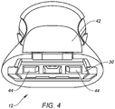
Fig. 4 is a top end view ofFig. 3 ; -
Fig. 5 is a partial sectional view ofFig. 3 ; -
Fig. 6 is a bottom end view of the connector of the razor cartridge of the safety razor ofFig. 1 ; -
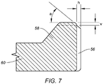
Fig. 7 is a side view ofFig. 6 ; -
Fig. 8 is a lower perspective view of another connector; -
Fig. 9 is an upper perspective view of the connector ofFig. 8 ; -
Fig 10 is a bottom plan view of the connector ofFig. 8 ; -
Fig. 11 is a sectional view ofFig. 10 taken at 11-11; and -
Fig 12 is an opposed sectional view ofFig. 10 taken at 12-12. - Referring now to the drawings and in particular
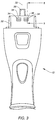
Figs. 1-2 , asafety razor 10 is depicted. Thesafety razor 10 comprises ahandle 12 having connected thereto arazor cartridge 14. In these figures and alsoFig. 3 thehandle 12 is shown truncated purely for the convenience of representing these figures at a suitable scale and the present invention is not limited in regard to the length or shape of thehandle 12. Therazor cartridge 14 comprises ahousing 16 with one ormore razor blades 18 mounted within thehousing 16. Thehousing 16 is supported by aconnector 20. In the depicted embodiment thehousing 16 can be pivotally supported by theconnector 20 such that thehousing 16 can pivot relative to theconnector 20 aboutpivot axis 24. In the depicted embodiment thehousing 16 has a pivotal support structure comprisingshell bearings 22 although the present disclosure should not be limited in this regard and other support methods such as pins in holes and so-called living hinges are within the scope of the present disclosure. Thehousing 16 can also be rigidly supported, e.g. non-pivotally supported by theconnector 20 or integrally formed with theconnector 20, for example as described inU.S. patent number 6,026,577 . - Both of the
housing 16 andconnector 20 are preferably made of suitable thermoplastic material(s) that can be the same or different. For example, thehousing 16 can be formed from injection molded acrylonitrile butadiene styrene (ABS) and the connector can be formed from injection molded polyoxymethylene (POM). Benefits of these materials include dimensional stability, resistance to chemicals typically found in use in a wet shaving environment and low friction of one sliding relative to the other during relative pivotal motion. -
Figs. 3-4 and5 depict respectively a front view, a top end view and a partial sectional view of thehandle 12. Thehandle 12 includes anextension 30 that engages arecess 50 of the connector 20 (seeFig. 6 ). Theextension 30 defines anaxis 32 along which therazor cartridge 14 moves relative to the handle when it is connect to and disconnected from thehandle 12. Theextension 30 includes a pair ofdepressions 34 that are preferably symmetrically arranged aboutaxis 32 or can be asymmetrically sized or arranged. Bothdepressions 34 have aleading edge 36 as will be described later in the present disclosure.Handle 12 includes anejector 40 that is slidable along the extension by a user operating abutton 42 connected to theejector 40.Ejector 40 can be U-shaped anddistal ends 44 of each leg of the U are adapted to contact respective interior surfaces (see 52 inFig. 6 ) of theconnector 20 of therazor cartridge 14 when a user operates thebutton 42 to disconnect or otherwise eject therazor cartridge 14 from thehandle 12. The handle can also be provided with a spring-biasedplunger 38 which can act through an opening of theconnector 20 in part defined by recess 50 (described later in the present disclosure). A distal end of theplunger 38 can act on a cam surface of thehousing 16 of therazor cartridge 14 to bias therazor cartridge 14 to a neutral or at-rest position when external forces (e.g. forces encountered during a shaving operation) are removed. A typical neural position is shown inFigs. 1 and 2 . - In
Fig. 6 a bottom end view of theconnector 20 of therazor cartridge 14 of thesafety razor 10 ofFig. 1 is depicted, i.e. a view of the entrance to therecess 50.Recess 50 is at least partially defined by opposed walls providing afloor 60 and aceiling 70 and byend walls recess 50 opposed the entrance, extending from thefloor 60 towards theceiling 70 and each end wall being adjacent arespective detent End walls interior surfaces 52 as described in the preceding paragraph.Recess 50 includes twodetents recess 50 from thefloor 60. As depicted inFig. 6 ,end wall 82 extends from thefloor 60 to theceiling 70 and connects thefloor 60 to theceiling 70.End wall 80 extends from thefloor 60 and agap 84 is provided between the top of thisend wall 80 andceiling 70 separating thisend wall 80 from theceiling 70. Inother embodiments gaps 84 can be provided between bothend walls ceiling 70. Alternatively, bothend walls floor 60 to theceiling 70. - In
Figs. 8-12 , anotherconnector 20 is depicted also having features as described above. This connector has opposed floor and ceiling walls (60, 70 respectively) partially defining arecess 50.Detents floor 60.End walls floor 60 towards theceiling 70.End wall 80interconnects floor 60 andceiling 70. Agap 84 is provided between the top ofend wall 82 and theceiling 70. Opposedarcuate bearing structures respective shell bearings 22 ofhousing 16 to provide pivotal movement ofhousing 16 relative toconnector 20 aboutpivot axis 24.Arcuate bearing structures arms -
Floor 60 includes acenter slot 90 positioned betweendetents lateral slot 92 is positioned on the opposed side ofdetent 56 at or close to a junction between thefloor 60 and a respectivelateral wall 100 of therecess 50. Preferably thelateral slot 92 is in thefloor 60. Both ofcenter slot 90 andlateral slot 92 preferably extend through or substantially through thefloor 60. Both ofcenter slot 90 andlateral slot 92 are sized (i.e. have a length in a direction parallel to axis 32) such that any movement or deflection of any onedetent other detent other detent detent handle extension depression 34 is substantially decoupled from engagement/disengagement of theother detent - As depicted in the embodiment of
figs. 8-12 (and alsoFig. 6 ), agap 84 is provided betweenend wall 80 andceiling 70. In conjunction withcenter slot 90 andlateral slot 92,detent 56 together with its local portion offloor 60 andend wall 80 acts as a unitary latching member when ejector legdistal end 44 acts on respectiveinterior surface 52 as a result of auser operating button 42 ofhandle 12 to eject thecartridge 14 from the handle. In thisembodiment end wall 82interconnects floor 60 toceiling 70 at or close todetent 58.Detent 58 with its local portion offloor 60 acts as a unitary snap fit in itsrespective depression 34 when ejector legdistal end 44 acts on respectiveinterior surface 52 as a result of auser operating button 42 ofhandle 12 to eject thecartridge 14 from the handle. In other words, one detent (e.g. 56) can act as a part of a unitary latching member independently of the other detent (e.g. 58) acting as a part of a unitary snap fit. - In
figs. 8-12 ,detents connector 20 through section cutting plane 11-11 / 12-12). Infig. 6 detents 56, 58 (as depicted) can have a different height "v" defined in a direction normal to the floor 60 (see alsoFig. 7 ). InFig. 7 , a partial sectional view ofFig. 6 , the leading edge (right hand side as depicted) ofdetent 56 can be offset relative to the leading edge ofdetent 58 by a distance "h" or onedetent cartridge 14 from thehandle 12detent 56 engages the leadingedge 36 of itsrespective depression 34 independently of the engagement betweendetent 58 engaging the leadingedge 36 of itsrespective depression 34. In this manner the engagement/disengagement of any onedetent other detent - Those skilled in the art will recognize that variations and modifications can be made without departing from the scope of the claims that follow. For example, the depressions can be provided in an interior wall of the recess and the detents provided on the outer surface(s) of the extension. The detents can be symmetrically arranged about the axis and the depressions can be asymmetric relative to the axis. Features disclosed in connection with any one embodiment can be used alone or in combination with each feature of the respective other embodiments.
Claims (19)
- A safety razor (10), comprising:a handle (12) having an extension (30) providing a cartridge support structure that engages a recess (50) of a razor cartridge (14), the extension (30) defining an axis (32) along which the razor cartridge (14) is moveable during connection to, and disconnection from, the extension (30); the extension (30) having a pair of depressions (34) to each receive a respective one of two detents (56, 58) of the razor cartridge (14);the handle (12) including a user-operable ejector (40), slidable along the extension (30) and adapted to engage the razor cartridge (14) to disconnect the razor cartridge (14) from the extension (30) of the handle (12); anda razor cartridge (14) comprising a blade (18) unit and a connector (20);wherein the recess (50) of the razor cartridge (14) is in part defined by opposed walls of the connector (20) providing a floor (60) and a ceiling (70) and the two detents (56, 58) are on the floor (60) and extend into the recess (50);wherein the floor (60) further has a center slot (90) between the two detents (56, 58) and the center slot (90) is sized such that deflection of any one detent (56, 58) on its respective floor (60) portion is substantially independent of deflection of the other detent (56, 58) on its respective floor (60) portion when the user-operable ejector (40) is operated to disconnect the razor cartridge (14) from the extension (30) of the handle (12).
- The safety razor (10) of claim 1, wherein the recess (50) is further defined by a lateral wall (100) and the floor (60) has a lateral slot (92) at or close to a junction between the floor (60) and the lateral wall (100).
- The safety razor (10) of claim 1 or claim 2, wherein the recess (50) is more further defined by two end walls (80, 82) at an end (44) of the recess (50) opposed an entrance of the recess (50), extending from the floor (60) towards the ceiling (70) and each end wall (80, 82) being adjacent a respective detent (56, 58).
- The safety razor (10) of claim 3, wherein at least one of the end walls (80, 82) extends from the floor (60) to the ceiling (70).
- The safety razor (10) claim 3, wherein a gap (84) is provided between at least one end wall (80, 82) and the ceiling (70), the gap (84) separating the end wall (80, 82) and the ceiling (70).
- The safety razor (10) of any preceding claim, wherein the detents (56, 58) are symmetrically sized and/or positioned about a center plane of the connector (20).
- The safety razor (10) of any of claim 1-5, wherein the detents (56, 58) are asymmetrically sized and/or positioned about a center plane of the connector (20).
- A razor cartridge (14) comprising a blade (18) unit and a connector (20); the connector (20) having a recess (50) in part defined by opposed walls of the connector (20) providing a floor (60) and a ceiling (70) and two detents (56, 58) extend from the floor (60) into the recess (50);
wherein the floor (60) further has a center slot (90) between the two detents (56, 58) and the center slot (90) is sized such that deflection of any one detent (56, 58) on its respective floor (60) portion is substantially independent of deflection of the other detent (56, 58) on its respective floor (60) portion when a deflection is imparted to any one of the two detents (56, 58). - The razor cartridge (14) of claim 8, wherein the recess (50) is further defined by a lateral wall (100) and the floor (60) has a lateral slot (92) at or close to a junction between the floor (60) and the lateral wall (100).
- The razor cartridge (14) of claim 8 or claim 9, wherein the recess (50) is more further defined by two end walls (80, 82) at an end (44) of the recess (50) opposed an entrance of the recess (50), extending from the floor (60) towards the ceiling (70) and each end wall (80, 82) being adjacent a respective detent (56, 58).
- The razor cartridge (14) of claim 10, wherein at least one of the end walls (80, 82) extends from the floor (60) to the ceiling (70).
- The razor cartridge (14) of claim 10, wherein a gap (84) is provided between at least one end wall (80, 82) and the ceiling (70).
- The razor cartridge (14) of any of claims 8-12, wherein the detents (56, 58) are symmetrically sized and/or positioned about a center plane of the connector (20).
- A connector (20) for a razor cartridge (14);
the connector (20) having a recess (50) in part defined by opposed walls of the connector (20) providing a floor (60) and a ceiling (70) and two detents (56, 58) extend from the floor (60) into the recess (50); wherein the floor (60) further has a center slot (90) between the two detents (56, 58) and the center slot (90) is sized such that deflection of any one detent (56, 58) on its respective floor (60) portion is substantially independent of deflection of the other detent (56, 58) on its respective floor (60) portion when a deflection is imparted to any one of the two detents (56, 58). - The connector (20) of claim 14, wherein the recess (50) is further defined by a lateral wall (100) and the floor (60) has a lateral slot (92) at or close to a junction between the floor (60) and the lateral wall (100).
- The connector (20) of claim 14 or claim 15, wherein the recess (50) is more further defined by two end walls (80, 82) at an end (44) of the recess (50) opposed an entrance of the recess (50), extending from the floor (60) towards the ceiling (70) and each end wall (80, 82) being adjacent a respective detent (56, 58).
- The connector (20) of any of claim 16, wherein at least one of the end walls (80, 82) extends from the floor (60) to the ceiling (70).
- The connector (20) of claim 16, wherein a gap (84) is provided between at least one end wall (80, 82) and the ceiling (70).
- The connector (20) of any of claims 14-18, wherein the detents (56, 58) are symmetrically sized and/or positioned about a center plane of the connector (20).
Priority Applications (1)
| Application Number | Priority Date | Filing Date | Title |
|---|---|---|---|
| PL18765304T PL3565690T3 (en) | 2017-08-28 | 2018-08-23 | Razor cartridge connector |
Applications Claiming Priority (2)
| Application Number | Priority Date | Filing Date | Title |
|---|---|---|---|
| US201762550930P | 2017-08-28 | 2017-08-28 | |
| PCT/US2018/047752 WO2019046097A1 (en) | 2017-08-28 | 2018-08-23 | Razor cartridge connector |
Publications (2)
| Publication Number | Publication Date |
|---|---|
| EP3565690A1 EP3565690A1 (en) | 2019-11-13 |
| EP3565690B1 true EP3565690B1 (en) | 2020-05-13 |
Family
ID=63490749
Family Applications (1)
| Application Number | Title | Priority Date | Filing Date |
|---|---|---|---|
| EP18765304.3A Active EP3565690B1 (en) | 2017-08-28 | 2018-08-23 | Razor cartridge connector |
Country Status (5)
| Country | Link |
|---|---|
| US (1) | US11285628B2 (en) |
| EP (1) | EP3565690B1 (en) |
| JP (1) | JP7164597B2 (en) |
| PL (1) | PL3565690T3 (en) |
| WO (1) | WO2019046097A1 (en) |
Families Citing this family (9)
| Publication number | Priority date | Publication date | Assignee | Title |
|---|---|---|---|---|
| JP6502487B2 (en) * | 2014-10-10 | 2019-04-17 | エッジウェル パーソナル ケア ブランズ リミテッド ライアビリティ カンパニーEdgewell Personal Care Brands, LLC | Universal razor cartridge handle |
| KR101703514B1 (en) | 2016-06-24 | 2017-02-07 | 주식회사 도루코 | Razor |
| PL3565690T3 (en) * | 2017-08-28 | 2020-11-16 | Edgewell Personal Care Brands, Llc | Razor cartridge connector |
| PL3717186T3 (en) * | 2017-11-28 | 2022-07-11 | Edgewell Personal Care Brands, Llc | Razor handle |
| EP3771530A1 (en) * | 2019-07-31 | 2021-02-03 | Bic Violex S.A. | Mechanical assembly of a skin care device, skin care device and process for manufacturing thereof |
| EP3842196B1 (en) * | 2019-12-23 | 2023-09-13 | BIC Violex Single Member S.A. | Coupling mechanism |
| USD935696S1 (en) | 2020-02-03 | 2021-11-09 | Edgewell Personal Care Brands, Llc | Razor cartridge connector |
| USD935096S1 (en) | 2020-02-03 | 2021-11-02 | Edgewell Personal Care Brands, Llc | Razor cartridge connector |
| USD935695S1 (en) | 2020-02-03 | 2021-11-09 | Edgewell Personal Care Brands, Llc | Razor cartridge connector |
Family Cites Families (21)
| Publication number | Priority date | Publication date | Assignee | Title |
|---|---|---|---|---|
| US4411065A (en) | 1982-02-25 | 1983-10-25 | The Gillette Company | Shaving cartridge assembly |
| US4413411A (en) | 1982-02-25 | 1983-11-08 | The Gillette Company | Razor handle |
| US4422237A (en) | 1982-02-25 | 1983-12-27 | The Gillette Company | Razor handle |
| US4446619A (en) | 1982-06-07 | 1984-05-08 | The Gillette Company | Razor handle |
| US4599793A (en) | 1984-05-23 | 1986-07-15 | American Safety Razor Company | Razor connector |
| US4901437A (en) | 1984-05-25 | 1990-02-20 | American Safety Razor Company | Razor head and method of manufacture |
| US6026577A (en) | 1993-10-15 | 2000-02-22 | Warner-Lambert Company | Disposable razor with removable razor head |
| US5956851A (en) | 1996-04-10 | 1999-09-28 | The Gillette Company | Shaving system including handle and replaceable cartridges |
| US5787586A (en) | 1996-04-10 | 1998-08-04 | The Gillette Company | Shaving system and method |
| EP1252983A3 (en) | 2001-04-27 | 2002-11-13 | Warner-Lambert Company | Cartridge loading system for a razor assembly |
| US7669335B2 (en) * | 2004-03-11 | 2010-03-02 | The Gillette Company | Shaving razors and shaving cartridges |
| US7168173B2 (en) | 2004-03-11 | 2007-01-30 | The Gillette Company | Shaving system |
| US7690122B2 (en) | 2004-03-11 | 2010-04-06 | The Gillette Company | Shaving razor with button |
| US8033023B2 (en) * | 2004-10-20 | 2011-10-11 | The Gillette Company | Shaving razors and cartridges |
| US20110088269A1 (en) * | 2009-10-21 | 2011-04-21 | Walker Jr Vincent Paul | Docking Mechanisms for Shaving Razors and Cartridges |
| US8793880B2 (en) * | 2010-02-16 | 2014-08-05 | The Gillette Company | Shaving razor adapter attaching a shaving razor cartridge to a shaving razor handle |
| PL3206844T3 (en) | 2014-10-15 | 2019-03-29 | Edgewell Personal Care Brands, Llc | Razor cartridge connector |
| US20170087733A1 (en) | 2015-09-29 | 2017-03-30 | The Gillette Company | Kit Comprising A Razor Cartridge And An Adapter |
| US11052558B2 (en) * | 2016-05-31 | 2021-07-06 | The Gillette Company Llc | Adapter for a handle and a cartridge of different razor systems |
| US10137584B2 (en) * | 2016-05-31 | 2018-11-27 | The Gillette Company Llc | Adapter for a handle and a cartridge of different razor systems |
| PL3565690T3 (en) * | 2017-08-28 | 2020-11-16 | Edgewell Personal Care Brands, Llc | Razor cartridge connector |
-
2018
- 2018-08-23 PL PL18765304T patent/PL3565690T3/en unknown
- 2018-08-23 WO PCT/US2018/047752 patent/WO2019046097A1/en unknown
- 2018-08-23 EP EP18765304.3A patent/EP3565690B1/en active Active
- 2018-08-23 US US16/641,283 patent/US11285628B2/en active Active
- 2018-08-23 JP JP2020512466A patent/JP7164597B2/en active Active
Non-Patent Citations (1)
| Title |
|---|
| None * |
Also Published As
| Publication number | Publication date |
|---|---|
| PL3565690T3 (en) | 2020-11-16 |
| EP3565690A1 (en) | 2019-11-13 |
| JP2020531202A (en) | 2020-11-05 |
| JP7164597B2 (en) | 2022-11-01 |
| US20200180177A1 (en) | 2020-06-11 |
| US11285628B2 (en) | 2022-03-29 |
| WO2019046097A1 (en) | 2019-03-07 |
Similar Documents
| Publication | Publication Date | Title |
|---|---|---|
| EP3565690B1 (en) | Razor cartridge connector | |
| JP6502487B2 (en) | Universal razor cartridge handle | |
| JP6588162B2 (en) | Handle assembly and razor including the same | |
| EP1597029B1 (en) | Shaving implement | |
| EP1809449B1 (en) | Shaving razors and cartridges | |
| EP3227065B1 (en) | A shaver's handle with a lock and release mechanism for engaging and disengaging a razor cartridge | |
| EP2892697B1 (en) | Safety razor | |
| JP2010536458A (en) | Razor with blade unit biasing member | |
| SK287062B6 (en) | Shaving system including handle and replaceable cartridge | |
| EP3378611B1 (en) | Razor | |
| JP7235746B2 (en) | razor handle | |
| EP3206844B1 (en) | Razor cartridge connector | |
| EP4311639A1 (en) | Razor assembly | |
| KR20240014433A (en) | Razor Assembly |
Legal Events
| Date | Code | Title | Description |
|---|---|---|---|
| STAA | Information on the status of an ep patent application or granted ep patent |
Free format text: STATUS: UNKNOWN |
|
| STAA | Information on the status of an ep patent application or granted ep patent |
Free format text: STATUS: THE INTERNATIONAL PUBLICATION HAS BEEN MADE |
|
| PUAI | Public reference made under article 153(3) epc to a published international application that has entered the european phase |
Free format text: ORIGINAL CODE: 0009012 |
|
| STAA | Information on the status of an ep patent application or granted ep patent |
Free format text: STATUS: REQUEST FOR EXAMINATION WAS MADE |
|
| 17P | Request for examination filed |
Effective date: 20190806 |
|
| AK | Designated contracting states |
Kind code of ref document: A1 Designated state(s): AL AT BE BG CH CY CZ DE DK EE ES FI FR GB GR HR HU IE IS IT LI LT LU LV MC MK MT NL NO PL PT RO RS SE SI SK SM TR |
|
| AX | Request for extension of the european patent |
Extension state: BA ME |
|
| GRAP | Despatch of communication of intention to grant a patent |
Free format text: ORIGINAL CODE: EPIDOSNIGR1 |
|
| STAA | Information on the status of an ep patent application or granted ep patent |
Free format text: STATUS: GRANT OF PATENT IS INTENDED |
|
| INTG | Intention to grant announced |
Effective date: 20191121 |
|
| GRAS | Grant fee paid |
Free format text: ORIGINAL CODE: EPIDOSNIGR3 |
|
| GRAA | (expected) grant |
Free format text: ORIGINAL CODE: 0009210 |
|
| STAA | Information on the status of an ep patent application or granted ep patent |
Free format text: STATUS: THE PATENT HAS BEEN GRANTED |
|
| DAV | Request for validation of the european patent (deleted) | ||
| DAX | Request for extension of the european patent (deleted) | ||
| AK | Designated contracting states |
Kind code of ref document: B1 Designated state(s): AL AT BE BG CH CY CZ DE DK EE ES FI FR GB GR HR HU IE IS IT LI LT LU LV MC MK MT NL NO PL PT RO RS SE SI SK SM TR |
|
| REG | Reference to a national code |
Ref country code: GB Ref legal event code: FG4D |
|
| REG | Reference to a national code |
Ref country code: CH Ref legal event code: EP |
|
| REG | Reference to a national code |
Ref country code: DE Ref legal event code: R096 Ref document number: 602018004677 Country of ref document: DE |
|
| REG | Reference to a national code |
Ref country code: AT Ref legal event code: REF Ref document number: 1269662 Country of ref document: AT Kind code of ref document: T Effective date: 20200615 |
|
| REG | Reference to a national code |
Ref country code: LT Ref legal event code: MG4D |
|
| REG | Reference to a national code |
Ref country code: GR Ref legal event code: EP Ref document number: 20200402243 Country of ref document: GR Effective date: 20201014 Ref country code: NL Ref legal event code: MP Effective date: 20200513 |
|
| PG25 | Lapsed in a contracting state [announced via postgrant information from national office to epo] |
Ref country code: IS Free format text: LAPSE BECAUSE OF FAILURE TO SUBMIT A TRANSLATION OF THE DESCRIPTION OR TO PAY THE FEE WITHIN THE PRESCRIBED TIME-LIMIT Effective date: 20200913 Ref country code: PT Free format text: LAPSE BECAUSE OF FAILURE TO SUBMIT A TRANSLATION OF THE DESCRIPTION OR TO PAY THE FEE WITHIN THE PRESCRIBED TIME-LIMIT Effective date: 20200914 Ref country code: NO Free format text: LAPSE BECAUSE OF FAILURE TO SUBMIT A TRANSLATION OF THE DESCRIPTION OR TO PAY THE FEE WITHIN THE PRESCRIBED TIME-LIMIT Effective date: 20200813 Ref country code: FI Free format text: LAPSE BECAUSE OF FAILURE TO SUBMIT A TRANSLATION OF THE DESCRIPTION OR TO PAY THE FEE WITHIN THE PRESCRIBED TIME-LIMIT Effective date: 20200513 Ref country code: SE Free format text: LAPSE BECAUSE OF FAILURE TO SUBMIT A TRANSLATION OF THE DESCRIPTION OR TO PAY THE FEE WITHIN THE PRESCRIBED TIME-LIMIT Effective date: 20200513 Ref country code: LT Free format text: LAPSE BECAUSE OF FAILURE TO SUBMIT A TRANSLATION OF THE DESCRIPTION OR TO PAY THE FEE WITHIN THE PRESCRIBED TIME-LIMIT Effective date: 20200513 |
|
| PG25 | Lapsed in a contracting state [announced via postgrant information from national office to epo] |
Ref country code: BG Free format text: LAPSE BECAUSE OF FAILURE TO SUBMIT A TRANSLATION OF THE DESCRIPTION OR TO PAY THE FEE WITHIN THE PRESCRIBED TIME-LIMIT Effective date: 20200813 Ref country code: RS Free format text: LAPSE BECAUSE OF FAILURE TO SUBMIT A TRANSLATION OF THE DESCRIPTION OR TO PAY THE FEE WITHIN THE PRESCRIBED TIME-LIMIT Effective date: 20200513 Ref country code: LV Free format text: LAPSE BECAUSE OF FAILURE TO SUBMIT A TRANSLATION OF THE DESCRIPTION OR TO PAY THE FEE WITHIN THE PRESCRIBED TIME-LIMIT Effective date: 20200513 Ref country code: HR Free format text: LAPSE BECAUSE OF FAILURE TO SUBMIT A TRANSLATION OF THE DESCRIPTION OR TO PAY THE FEE WITHIN THE PRESCRIBED TIME-LIMIT Effective date: 20200513 |
|
| REG | Reference to a national code |
Ref country code: AT Ref legal event code: MK05 Ref document number: 1269662 Country of ref document: AT Kind code of ref document: T Effective date: 20200513 |
|
| PG25 | Lapsed in a contracting state [announced via postgrant information from national office to epo] |
Ref country code: NL Free format text: LAPSE BECAUSE OF FAILURE TO SUBMIT A TRANSLATION OF THE DESCRIPTION OR TO PAY THE FEE WITHIN THE PRESCRIBED TIME-LIMIT Effective date: 20200513 Ref country code: AL Free format text: LAPSE BECAUSE OF FAILURE TO SUBMIT A TRANSLATION OF THE DESCRIPTION OR TO PAY THE FEE WITHIN THE PRESCRIBED TIME-LIMIT Effective date: 20200513 |
|
| PG25 | Lapsed in a contracting state [announced via postgrant information from national office to epo] |
Ref country code: AT Free format text: LAPSE BECAUSE OF FAILURE TO SUBMIT A TRANSLATION OF THE DESCRIPTION OR TO PAY THE FEE WITHIN THE PRESCRIBED TIME-LIMIT Effective date: 20200513 Ref country code: DK Free format text: LAPSE BECAUSE OF FAILURE TO SUBMIT A TRANSLATION OF THE DESCRIPTION OR TO PAY THE FEE WITHIN THE PRESCRIBED TIME-LIMIT Effective date: 20200513 Ref country code: SM Free format text: LAPSE BECAUSE OF FAILURE TO SUBMIT A TRANSLATION OF THE DESCRIPTION OR TO PAY THE FEE WITHIN THE PRESCRIBED TIME-LIMIT Effective date: 20200513 Ref country code: EE Free format text: LAPSE BECAUSE OF FAILURE TO SUBMIT A TRANSLATION OF THE DESCRIPTION OR TO PAY THE FEE WITHIN THE PRESCRIBED TIME-LIMIT Effective date: 20200513 Ref country code: IT Free format text: LAPSE BECAUSE OF FAILURE TO SUBMIT A TRANSLATION OF THE DESCRIPTION OR TO PAY THE FEE WITHIN THE PRESCRIBED TIME-LIMIT Effective date: 20200513 Ref country code: RO Free format text: LAPSE BECAUSE OF FAILURE TO SUBMIT A TRANSLATION OF THE DESCRIPTION OR TO PAY THE FEE WITHIN THE PRESCRIBED TIME-LIMIT Effective date: 20200513 Ref country code: ES Free format text: LAPSE BECAUSE OF FAILURE TO SUBMIT A TRANSLATION OF THE DESCRIPTION OR TO PAY THE FEE WITHIN THE PRESCRIBED TIME-LIMIT Effective date: 20200513 Ref country code: CZ Free format text: LAPSE BECAUSE OF FAILURE TO SUBMIT A TRANSLATION OF THE DESCRIPTION OR TO PAY THE FEE WITHIN THE PRESCRIBED TIME-LIMIT Effective date: 20200513 |
|
| REG | Reference to a national code |
Ref country code: DE Ref legal event code: R097 Ref document number: 602018004677 Country of ref document: DE |
|
| PG25 | Lapsed in a contracting state [announced via postgrant information from national office to epo] |
Ref country code: SK Free format text: LAPSE BECAUSE OF FAILURE TO SUBMIT A TRANSLATION OF THE DESCRIPTION OR TO PAY THE FEE WITHIN THE PRESCRIBED TIME-LIMIT Effective date: 20200513 |
|
| PLBE | No opposition filed within time limit |
Free format text: ORIGINAL CODE: 0009261 |
|
| STAA | Information on the status of an ep patent application or granted ep patent |
Free format text: STATUS: NO OPPOSITION FILED WITHIN TIME LIMIT |
|
| PG25 | Lapsed in a contracting state [announced via postgrant information from national office to epo] |
Ref country code: MC Free format text: LAPSE BECAUSE OF FAILURE TO SUBMIT A TRANSLATION OF THE DESCRIPTION OR TO PAY THE FEE WITHIN THE PRESCRIBED TIME-LIMIT Effective date: 20200513 |
|
| 26N | No opposition filed |
Effective date: 20210216 |
|
| PG25 | Lapsed in a contracting state [announced via postgrant information from national office to epo] |
Ref country code: LU Free format text: LAPSE BECAUSE OF NON-PAYMENT OF DUE FEES Effective date: 20200823 |
|
| REG | Reference to a national code |
Ref country code: BE Ref legal event code: MM Effective date: 20200831 |
|
| PG25 | Lapsed in a contracting state [announced via postgrant information from national office to epo] |
Ref country code: IE Free format text: LAPSE BECAUSE OF NON-PAYMENT OF DUE FEES Effective date: 20200823 Ref country code: BE Free format text: LAPSE BECAUSE OF NON-PAYMENT OF DUE FEES Effective date: 20200831 |
|
| REG | Reference to a national code |
Ref country code: CH Ref legal event code: PL |
|
| PG25 | Lapsed in a contracting state [announced via postgrant information from national office to epo] |
Ref country code: LI Free format text: LAPSE BECAUSE OF NON-PAYMENT OF DUE FEES Effective date: 20210831 Ref country code: CH Free format text: LAPSE BECAUSE OF NON-PAYMENT OF DUE FEES Effective date: 20210831 |
|
| PG25 | Lapsed in a contracting state [announced via postgrant information from national office to epo] |
Ref country code: TR Free format text: LAPSE BECAUSE OF FAILURE TO SUBMIT A TRANSLATION OF THE DESCRIPTION OR TO PAY THE FEE WITHIN THE PRESCRIBED TIME-LIMIT Effective date: 20200513 Ref country code: MT Free format text: LAPSE BECAUSE OF FAILURE TO SUBMIT A TRANSLATION OF THE DESCRIPTION OR TO PAY THE FEE WITHIN THE PRESCRIBED TIME-LIMIT Effective date: 20200513 Ref country code: CY Free format text: LAPSE BECAUSE OF FAILURE TO SUBMIT A TRANSLATION OF THE DESCRIPTION OR TO PAY THE FEE WITHIN THE PRESCRIBED TIME-LIMIT Effective date: 20200513 |
|
| PG25 | Lapsed in a contracting state [announced via postgrant information from national office to epo] |
Ref country code: MK Free format text: LAPSE BECAUSE OF FAILURE TO SUBMIT A TRANSLATION OF THE DESCRIPTION OR TO PAY THE FEE WITHIN THE PRESCRIBED TIME-LIMIT Effective date: 20200513 |
|
| P01 | Opt-out of the competence of the unified patent court (upc) registered |
Effective date: 20230526 |
|
| PG25 | Lapsed in a contracting state [announced via postgrant information from national office to epo] |
Ref country code: SI Free format text: LAPSE BECAUSE OF FAILURE TO SUBMIT A TRANSLATION OF THE DESCRIPTION OR TO PAY THE FEE WITHIN THE PRESCRIBED TIME-LIMIT Effective date: 20200513 |
|
| PGFP | Annual fee paid to national office [announced via postgrant information from national office to epo] |
Ref country code: GB Payment date: 20230828 Year of fee payment: 6 |
|
| PGFP | Annual fee paid to national office [announced via postgrant information from national office to epo] |
Ref country code: PL Payment date: 20230802 Year of fee payment: 6 Ref country code: GR Payment date: 20230829 Year of fee payment: 6 Ref country code: FR Payment date: 20230825 Year of fee payment: 6 Ref country code: DE Payment date: 20230829 Year of fee payment: 6 |