RU2263024C2 - Razor handle and rod for razor handle - Google Patents
Razor handle and rod for razor handle Download PDFInfo
- Publication number
- RU2263024C2 RU2263024C2 RU2002122571/12A RU2002122571A RU2263024C2 RU 2263024 C2 RU2263024 C2 RU 2263024C2 RU 2002122571/12 A RU2002122571/12 A RU 2002122571/12A RU 2002122571 A RU2002122571 A RU 2002122571A RU 2263024 C2 RU2263024 C2 RU 2263024C2
- Authority
- RU
- Russia
- Prior art keywords
- cartridge
- support device
- razor handle
- gripping
- handle
- Prior art date
Links
Images
Classifications
-
- B—PERFORMING OPERATIONS; TRANSPORTING
- B26—HAND CUTTING TOOLS; CUTTING; SEVERING
- B26B—HAND-HELD CUTTING TOOLS NOT OTHERWISE PROVIDED FOR
- B26B21/00—Razors of the open or knife type; Safety razors or other shaving implements of the planing type; Hair-trimming devices involving a razor-blade; Equipment therefor
- B26B21/40—Details or accessories
- B26B21/52—Handles, e.g. tiltable, flexible
- B26B21/528—Manufacture of razor handles
-
- B—PERFORMING OPERATIONS; TRANSPORTING
- B26—HAND CUTTING TOOLS; CUTTING; SEVERING
- B26B—HAND-HELD CUTTING TOOLS NOT OTHERWISE PROVIDED FOR
- B26B21/00—Razors of the open or knife type; Safety razors or other shaving implements of the planing type; Hair-trimming devices involving a razor-blade; Equipment therefor
- B26B21/08—Razors of the open or knife type; Safety razors or other shaving implements of the planing type; Hair-trimming devices involving a razor-blade; Equipment therefor involving changeable blades
- B26B21/14—Safety razors with one or more blades arranged transversely to the handle
- B26B21/22—Safety razors with one or more blades arranged transversely to the handle involving several blades to be used simultaneously
- B26B21/222—Safety razors with one or more blades arranged transversely to the handle involving several blades to be used simultaneously with the blades moulded into, or attached to, a changeable unit
- B26B21/225—Safety razors with one or more blades arranged transversely to the handle involving several blades to be used simultaneously with the blades moulded into, or attached to, a changeable unit the changeable unit being resiliently mounted on the handle
-
- B—PERFORMING OPERATIONS; TRANSPORTING
- B26—HAND CUTTING TOOLS; CUTTING; SEVERING
- B26B—HAND-HELD CUTTING TOOLS NOT OTHERWISE PROVIDED FOR
- B26B21/00—Razors of the open or knife type; Safety razors or other shaving implements of the planing type; Hair-trimming devices involving a razor-blade; Equipment therefor
- B26B21/40—Details or accessories
- B26B21/4012—Housing details, e.g. for cartridges
-
- B—PERFORMING OPERATIONS; TRANSPORTING
- B26—HAND CUTTING TOOLS; CUTTING; SEVERING
- B26B—HAND-HELD CUTTING TOOLS NOT OTHERWISE PROVIDED FOR
- B26B21/00—Razors of the open or knife type; Safety razors or other shaving implements of the planing type; Hair-trimming devices involving a razor-blade; Equipment therefor
- B26B21/40—Details or accessories
- B26B21/4068—Mounting devices; Manufacture of razors or cartridges
-
- B—PERFORMING OPERATIONS; TRANSPORTING
- B26—HAND CUTTING TOOLS; CUTTING; SEVERING
- B26B—HAND-HELD CUTTING TOOLS NOT OTHERWISE PROVIDED FOR
- B26B21/00—Razors of the open or knife type; Safety razors or other shaving implements of the planing type; Hair-trimming devices involving a razor-blade; Equipment therefor
- B26B21/40—Details or accessories
- B26B21/52—Handles, e.g. tiltable, flexible
- B26B21/521—Connection details, e.g. connection to razor heads
Abstract
Description
Изобретение касается бритвенных систем, имеющих ручки и сменные картриджи.The invention relates to shaving systems having handles and replaceable cartridges.
Бритвенные системы часто состоят из ручки и сменного картриджа, в котором одно или более лезвий установлены в пластмассовом корпусе. После того как лезвия в картридже затупляются от использования, картридж выбрасывают и на ручке устанавливают новый картридж. В некоторых бритвенных системах лезвия упруго устанавливаются относительно корпуса картриджа и отклоняются под воздействием контакта с кожей во время бритья. В некоторых бритвенных системах соединение картриджа с ручкой обеспечивает установку с возможностью поворота картриджа относительно ручки так, что угол наклона картриджа регулируется, чтобы соответствовать контурам выбриваемой поверхности. В таких системах картридж может быть подпружинен в направлении нерабочего положения под действием подпружиненного плунжера (кулачкового толкателя), расположенного на ручке напротив криволинейной поверхности на корпусе картриджа.Shaving systems often consist of a handle and a replaceable cartridge in which one or more blades are mounted in a plastic case. After the blades in the cartridge become dull from use, the cartridge is discarded and a new cartridge is installed on the handle. In some shaving systems, the blades are resiliently mounted relative to the cartridge body and deflected due to skin contact during shaving. In some shaving systems, connecting the cartridge to the handle allows the cartridge to be rotated relative to the handle so that the angle of inclination of the cartridge is adjusted to fit the contours of the surface being shaved. In such systems, the cartridge can be spring-loaded in the direction of the inoperative position under the action of a spring-loaded plunger (cam follower) located on the handle opposite the curved surface on the cartridge body.
Были предложены многокомпонентные ручки бритвы в различных формах выполнения. Тремя такими составными ручками, которые представлены на рынке, являются ручки бритвы Schick Tracer FX и Silk Effect, а также ручки бритвы Wilkinson Sword "Protector".Multicomponent razor handles in various embodiments have been proposed. Three of these compound pens on the market are the Schick Tracer FX and Silk Effect razor handles, as well as the Wilkinson Sword "Protector" razor handles.
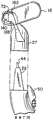
На прилагаемых четырех фотографиях показана такая разобранная металлическая ручка бритвы Schick Tracer FX с резиновым захватываемым рукой элементом.The attached four photographs show such a disassembled metal handle of the Schick Tracer FX razor with a rubber hand-gripping element.
На верхней левой фотографии показаны детали разобранной ручки, которые в собранном состоянии составляют металлическую ручку, имеющую открытую нижнюю сторону и паз в ее верхней поверхности. Самым верхним элементом, показанным на верхней левой фотографии, является верхняя пластмассовая полоска. Самым нижним элементом, показанным на этой фотографии, является нижний захватываемый рукой элемент, который сформирован из резинового внешнего материала, накладываемого на более жесткий пластмассовый каркас, приспособленный для соединения с защелкиванием.The upper left photo shows the details of the disassembled handle, which, when assembled, make up a metal handle having an open lower side and a groove in its upper surface. The topmost item shown in the upper left photo is the upper plastic strip. The lowest element shown in this photograph is the lower hand-gripped element, which is formed of a rubber outer material overlaid on a stiffer plastic frame adapted to snap into place.
Внутренняя полость ручки имеет четыре упорных уступа. Вертикальный центральный каркас нижнего захватываемого рукой элемента имеет четыре защелкивающиеся поверхности, которые соответствуют расположению подрезов на верхних районах каждого из четырех упорных уступов ручки. На ручке сформированы два штырька, по одному на каждом конце полости ручки, которые вставляют в соответствующие отверстия в жестком пластмассовом элементе нижней захватываемой рукой части.The internal cavity of the handle has four thrust ledges. The vertical central frame of the lower hand-gripping element has four snap surfaces that correspond to the location of the cuts in the upper regions of each of the four thrust ledges of the handle. Two pins are formed on the handle, one at each end of the handle cavity, which is inserted into the corresponding holes in the rigid plastic element of the lower hand-held part.
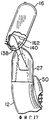
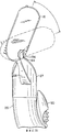
Верхнюю полоску формируют из пластмассы и она имеет четыре вырезанных участка для получения зазора вокруг оснований четырех упоров ручки таким образом, что полоска скользит в паз, как показано на верхней правой и нижней левой фотографиях, и в собранном состоянии немного выступает от внешней поверхности в центре верхней поверхности ручки, как показано на нижней правой фотографии. Верхняя полоска удерживается на месте благодаря вхождению в контакт с центральной самой верхней частью каркаса нижнего захватываемого рукой элемента, когда нижний захватываемый рукой элемент собран в составе ручки.The upper strip is formed of plastic and it has four cut sections to obtain a gap around the bases of the four stops of the handle so that the strip slides into the groove, as shown in the upper right and lower left photographs, and in the assembled state protrudes slightly from the outer surface in the center of the upper handle surface as shown in the lower right photo. The upper strip is held in place by coming into contact with the central most upper part of the frame of the lower hand-gripping element when the lower hand-gripping element is assembled as a part of the handle.
Представляется, что это изделие было в продаже в Соединенных Штатах Америки с сентября 1995 года или позже.This product appears to have been on sale in the United States since September 1995 or later.
На прилагаемых четырех фотографиях показана такая разобранная ручка бритвы, поставляемая под торговой маркой Schick "Silk Effects" компанией Warner Lambert.The attached four photographs show such a disassembled razor handle, sold under the trademark Schick "Silk Effects" by Warner Lambert.
Верхняя и нижняя оболочки ручки выполнены из твердой белой пластмассы. Две оболочки соединяют при помощи одиннадцати точек соединения штырьками, вставляемыми в отверстия, с использованием клейкого вещества, в целом показанных на фотографиях как белесоватые районы вокруг периферии в форме песочных часов, где штырьки срезаны при разборке. Между половинами из оболочек расположена пластмассовая вставка в форме языка.The upper and lower shells of the handle are made of solid white plastic. The two shells are connected using eleven connection points with pins inserted into the holes using an adhesive, generally shown in the photographs as whitish areas around the periphery in the form of an hourglass, where the pins are cut off during disassembly. A plastic tongue-shaped insert is located between the halves of the shells.
В нижней оболочке выполнен вырез, через который можно видеть пурпурную пластмассовую вкладку. Пурпурная вкладка свободно лежит на нижней поверхности пластмассовой вставки и расположена между вставкой и внутренней поверхностью нижней оболочки ручки.A cutout is made in the lower shell, through which you can see the purple plastic tab. The purple tab lies freely on the lower surface of the plastic insert and is located between the insert and the inner surface of the lower shell of the handle.
Пластмассовую вставку свободно помещают в обе половины оболочки и позиционируют ее стороны выступами, отходящими от половин оболочек, которые входят в контакт с периферийными боковыми поверхностями вставки. Применяют семь полукруглых выемок, расположенных по периферии вставки, которые имеют размеры, достаточно большие для свободного насаживания на (и при разборке - съема) семь приливов, расположенных вдоль каждой половины ручки по ее периферии. В состоянии, когда оболочки ручки соединены друг с другом, приливы и выемки ориентируют вставку в продольном направлении. Однако приливы на половинах ручки не защелкиваются относительно вставки, а скорее две половины ручки из жесткой пластмассы удерживаются только относительно друг друга и это зависит от того, помещена ли между ними вставка.The plastic insert is freely placed in both halves of the shell and its sides are positioned with protrusions extending from the halves of the shells that come into contact with the peripheral side surfaces of the insert. Apply seven semicircular grooves located on the periphery of the insert, which are large enough to freely fit on (and when disassembling - removing) seven tides located along each half of the handle on its periphery. In a state where the handle shells are connected to each other, tides and recesses orient the insert in the longitudinal direction. However, the tides on the handle halves do not snap relative to the insert, but rather the two halves of the rigid plastic handle are held only relative to each other and this depends on whether the insert is placed between them.
Применяют также тонкую штампованную стальную вставку из листового металла, сформированную в конфигурации удлиненной U-образной вилки, расположенной между внутренней поверхностью верхней половины оболочки и верхней поверхностью пластмассовой вставки, и формирующей ветви для удерживания картриджа; причем ветви вилки принудительно направляются друг к другу под воздействием кулачка при сдвиге кнопки (не показана) на верхней внешней поверхности для отсоединения дальних концов ветвей от картриджа для его отделения.Also used is a thin stamped steel insert made of sheet metal formed in the configuration of an elongated U-shaped fork located between the inner surface of the upper half of the shell and the upper surface of the plastic insert and forming branches for holding the cartridge; moreover, the branches of the plug are forced to each other under the influence of the cam when the button (not shown) is shifted on the upper outer surface to disconnect the distal ends of the branches from the cartridge to separate it.
Представляется, что это изделие было в продаже в Соединенных Штатах Америки в 1994 году.This product appears to be on sale in the United States in 1994.
Кроме того, на прилагаемых трех фотографиях показана такая разобранная ручка бритвы Wilkinson Sword, поставляемая под торговой маркой "Protector" в Канаду в упаковке, помеченной надписью Warner Lambert Canada, Inc., "made in Germany."In addition, the attached three photographs show such a disassembled Wilkinson Sword razor handle sold under the Protector trademark in Canada in a package labeled Warner Lambert Canada, Inc., “made in Germany.”
На фотографиях показаны верхняя и нижняя оболочки ручки, выполненные из твердой пластмассы, имеющей красную окраску. Две половины ручки соединяют друг с другом и они удерживаются как единое целое при помощи восьми точек соединения штырьками, вставляемыми в отверстия, с использованием клейкого вещества, в целом показанных на фотографиях как белесоватые районы, где штырьки срезаны при разборке. Конструкция половин оболочки ручки в целом соответствует типу, показанному в патенте США №5031319 (Althaus и др.) на фиг.5-6.The photographs show the upper and lower shells of the handle made of hard plastic with a red color. The two halves of the handle are connected to each other and they are held together by means of eight connection points with pins inserted into the holes using an adhesive, generally shown in the photographs as whitish areas where the pins are cut off during disassembly. The design of the handle shell halves is generally consistent with the type shown in US Pat. No. 5,031,319 (Althaus et al.) In FIGS. 5-6.
Две круглые подушечки из вспененного материала приклеены на внешнюю поверхность нижней половины оболочки на расширенном конце ручки в два круглых углубления во внешней поверхности нижней половины оболочки (одна подушечка на фотографии отсутствует для демонстрации круглого углубления).Two round pads of foam material are glued to the outer surface of the lower half of the shell at the extended end of the handle in two round recesses in the outer surface of the lower half of the shell (one pillow is not shown in the photograph to demonstrate the round recess).
В нижнюю половину оболочки помещают металлическую вставку в форме полоски. Вставка находится между половинами оболочки ручки. Во вставке выполнены три установочных отверстия, имеющих достаточные размеры для насаживания (а при разборке - для съема) на три цилиндрических прилива, расположенных на центральной суженной продольной части ручки, причем два прилива расположены на нижней оболочке ручки и один прилив расположен на верхней оболочке ручки. В собранном состоянии отверстия и приливы ориентируют вставку в продольном направлении. Однако приливы на половинах ручки не защелкиваются относительно вставки, а скорее две половины ручки из жесткой пластмассы удерживаются только друг относительно друга и это зависит от того, помещена ли между ними вставка.A strip-shaped metal insert is placed in the lower half of the shell. The insert is between the halves of the handle shell. Three insertion holes are made in the insert, which are of sufficient size for mounting (and when dismantling, for removal) onto three cylindrical tides located on the central narrowed longitudinal part of the handle, with two tides located on the lower shell of the handle and one tide located on the upper shell of the handle. In the assembled state, the holes and tides orient the insert in the longitudinal direction. However, the tides on the handle halves do not snap relative to the insert, but rather the two halves of the rigid plastic handle are held only relative to each other and this depends on whether the insert is placed between them.
Применяют также тонкую штампованную стальную вставку из листового металла, сформированную в конфигурации удлиненной U-образной вилки, расположенной в верхней половине оболочки и формирующей ветви для удерживания картриджа; причем ветви вилки принудительно направляются друг к другу под воздействием кулачка при сдвиге кнопки (не показана) на верхней внешней поверхности для отсоединения дальних концов ветвей от картриджа для его отделения.Also used is a thin stamped steel sheet metal insert formed in the configuration of an elongated U-shaped fork located in the upper half of the shell and forming branches for holding the cartridge; moreover, the branches of the plug are forced to each other under the influence of the cam when the button (not shown) is shifted on the upper outer surface to disconnect the distal ends of the branches from the cartridge to separate it.
Представляется, что это изделие было в продаже в Канаде с февраля 1994 года или позже.This product appears to be on sale in Canada from February 1994 or later.
В общем, в одном аспекте, изобретение заключается в сменном бритвенном картридже, имеющем несущий лезвия корпус, предохранитель, крышку и кулачковую поверхность. Картридж также включает соединительный элемент, имеющий поворотное опорное устройство, которое поддерживает корпус с возможностью поворота, и основание, приспособленное для жесткого крепления к ручке с возможностью съема. Соединительный элемент обеспечивает доступ к кулачковой поверхности с помощью подпружиненного кулачкового толкателя на ручке.In general, in one aspect, the invention is a replaceable razor cartridge having a blade bearing body, a fuse, a cover, and a cam surface. The cartridge also includes a connecting element having a rotary support device that supports the housing with the possibility of rotation, and a base adapted for rigid fastening to the handle with the possibility of removal. The connecting element provides access to the cam surface using a spring-loaded cam follower on the handle.
В другом аспекте изобретение заключается в сменном бритвенном картридже, имеющем несущий лезвия корпус, предохранитель и крышку. Картридж также включает соединительный элемент, имеющий поворотное опорное устройство, которое удерживает корпус с возможностью поворота вокруг оси поворота, и основание, приспособленное для жесткого крепления к удлинению на конце ручки с возможностью съезда. Удлинение ручки имеет наружные боковые поверхности, а основание имеет выемку с направленными внутрь боковыми поверхностями, которые входят в зацепление с достаточным количеством наружных боковых поверхностей на удлинении ручки, чтобы неподвижно установить основание относительно удлинения ручки. Основание также имеет отверстие к выемке вдоль оси, не параллельной относительно оси поворота.In another aspect, the invention provides a replaceable razor cartridge having a blade bearing body, a fuse, and a cover. The cartridge also includes a connecting element having a rotary support device that holds the housing rotatably around the axis of rotation, and a base adapted for rigid attachment to the extension at the end of the handle with the possibility of exit. The handle extension has outer side surfaces, and the base has a recess with inwardly directed side surfaces that engage with a sufficient number of external side surfaces on the handle extension to immobilize the base relative to the handle extension. The base also has an opening to the recess along an axis not parallel to the axis of rotation.
В еще одном аспекте изобретение заключается в сменном бритвенном картридже, имеющем несущий лезвия корпус, предохранитель и крышку. Картридж также включает соединительный элемент, имеющий основание, предназначенное для съемного жесткого крепления к удлинению ручки, отходящему от ее конца вдоль оси. Удлинение ручки имеет наружные боковые поверхности и асимметричное сечение в плоскости, проходящей через боковые поверхности, перпендикулярные к оси удлинения. Основание имеет выемку, которая сопряжена с удлинением и имеет направленные внутрь боковые поверхности, которые входят в зацепление с достаточным количеством наружных боковых поверхностей вдоль асимметричного удлинения, чтобы неподвижно установить основание относительно удлинения и обеспечить правильное положение корпуса относительно ручки. Основание имеет отверстие к выемке вдоль оси, перпендикулярной к плоскости.In yet another aspect, the invention is a replaceable razor cartridge having a blade bearing body, a fuse, and a cover. The cartridge also includes a connecting element having a base designed for removable rigid fastening to the extension of the handle, extending from its end along the axis. The handle extension has outer side surfaces and an asymmetric section in a plane passing through the side surfaces perpendicular to the extension axis. The base has a recess that is associated with the extension and has inwardly directed side surfaces that engage with a sufficient number of external side surfaces along the asymmetric extension to immobilize the base relative to the extension and to ensure the correct position of the housing relative to the handle. The base has an opening to the recess along an axis perpendicular to the plane.
В еще одном аспекте изобретение заключается, в сущности, в сменном картридже лезвия бритвы, который включает узел лезвий бритвы и соединительное устройство картриджа для соединения узла лезвий бритвы с ручкой. Соединительное устройство картриджа имеет направленные внутрь поверхности, которые частично образуют участок для приема ручки и сопрягаются с направленными наружу поверхностями на устройстве соединения ручки. Устройство соединения картриджа также имеет вход соединения в участок для приема ручки и выступ, который проходит в участок для приема ручки. Выступ имеет блокирующую поверхность, обращенную в противоположном направлении от входа соединения для удержания устройства соединения ручки на устройстве соединения картриджа.In yet another aspect, the invention consists essentially of a replaceable razor blade cartridge that includes a razor blade assembly and a cartridge connecting device for connecting the razor blade assembly to a handle. The cartridge connecting device has inwardly directed surfaces that partially form a portion for receiving the handle and mates with outwardly facing surfaces on the handle connecting device. The cartridge connecting device also has a connection input to a handle receiving portion and a protrusion that extends to the handle receiving portion. The protrusion has a blocking surface facing in the opposite direction from the connection inlet to hold the handle connection device on the cartridge connection device.
В другом аспекте изобретение заключается в основном в сменном картридже узла бритвы, включающем узел лезвий, который соединен с возможностью поворота с устройством соединения картриджа, которое включает элемент задвижки, имеющий возможность перемещения, чтобы освободить картридж из ручки.In another aspect, the invention consists essentially of a replaceable cartridge for a razor assembly including a blade assembly that is rotatably coupled to a cartridge connection device that includes a slide member having a displacement feature to release the cartridge from the handle.
Определенные виды реализации изобретения включают один или более следующих признаков.Certain embodiments of the invention include one or more of the following features.
В некоторых случаях применения корпус имеет, по существу, свободный промывочный участок под лезвиями; поворотное опорное устройство имеет ось поворота впереди лезвий в области предохранителя. Форма выемки в основании может быть в виде трапеции, шестиугольника и/или быть сплющенной (плоской) в направлении, параллельном лезвиям.In some applications, the housing has a substantially free flushing area under the blades; the rotary support device has an axis of rotation in front of the blades in the area of the fuse. The shape of the recess in the base may be in the form of a trapezoid, a hexagon and / or be flattened (flat) in a direction parallel to the blades.
В некоторых случаях применения: основание вставляется защелкиванием в ручку; основание имеет фиксатор, а ручка имеет сопряженное углубление, приспособленное для вхождения фиксатора; в качестве альтернативы ручка имеет фиксатор, а основание имеет сопряженное углубление, предназначенное для вхождения фиксатора: используется несколько фиксаторов и углублений. В качестве альтернативы основание задвигается в ручку.In some applications: the base is snapped into the handle; the base has a latch, and the handle has a mating recess adapted for the entry of the latch; as an alternative, the handle has a latch, and the base has a mating recess intended for the latch to enter: several fixatives and recesses are used. Alternatively, the base slides into the handle.
В некоторых случаях применения: корпус и соединительный элемент выполнены из отдельных пластмассовых деталей. В других случаях корпус и элемент взаимосвязи выполнены как одно целое из пластмассы, а поворотное опорное устройство обеспечено подвижным шарниром. Или же поворотное опорное устройство обеспечено гибким пластмассовым шарниром, выполненным из материала, который более гибок, чем корпус, и соединяет корпус и соединительный элемент в области поворота.In some applications: the housing and the connecting element are made of separate plastic parts. In other cases, the housing and the interconnection element are made integrally of plastic, and the rotary support device is provided with a movable hinge. Or, the rotary support device is provided with a flexible plastic hinge made of a material that is more flexible than the body and connects the body and the connecting element in the area of rotation.
В некоторых случаях реализация изобретения: поворотное опорное устройство соединительного элемента включает два рычага, концы которых удерживаются в выемках с отверстиями с двух сторон корпуса; концы рычагов вставляются с усилием в выемки корпуса; выемки покрываются зажимами для удержания концов рычагов внутри выемок; рычаги имеют нижние поверхности, которые скользят на направленных вверх дугообразных поверхностях на корпусе.In some cases, the implementation of the invention: the rotary support device of the connecting element includes two levers, the ends of which are held in recesses with holes on both sides of the housing; the ends of the levers are inserted with force into the recesses of the housing; the recesses are covered with clamps to hold the ends of the levers inside the recesses; the levers have lower surfaces that slide on upwardly arched surfaces on the housing.
В некоторых случаях реализации корпус имеет кулачковую поверхность для приема поверхности кулачкового толкателя на подпружиненном плунжере от соединительного элемента; соединительный элемент имеет отверстие для приема подпружиненного плунжера; кулачковая поверхность дает возможность поворота только в одном направлении из нерабочего положения или дает возможность поворота на разные расстояния вперед и назад из нерабочего положения; корпус также имеет переднюю и заднюю поверхности упора, которые взаимодействуют с соединительным элементом.In some cases, the implementation of the housing has a cam surface for receiving the surface of the cam follower on a spring-loaded plunger from the connecting element; the connecting element has an opening for receiving a spring-loaded plunger; the cam surface allows rotation in only one direction from the idle position or allows rotation at different distances forward and backward from the idle position; the housing also has front and rear stop surfaces that interact with the connecting element.
В некоторых случаях применения: лезвия загружаются в корпус с верхней стороны корпуса; лезвия удерживаются в корпусе зажимами, которые удерживают соединительный элемент в нижней стороне корпуса; в корпусе установлены три лезвия; лезвия подпружинены (например, лезвия могут быть упруго установлены в корпусе с помощью пружинных рычагов, выполненных заодно с корпусом); предохранитель выполнен из эластомерного материала и имеет гибкие ребра для зацепления с кожей пользователя.In some applications: blades are loaded into the housing from the upper side of the housing; the blades are held in the housing by clamps that hold the connecting element in the lower side of the housing; three blades are installed in the case; the blades are spring-loaded (for example, the blades can be resiliently mounted in the casing using spring levers made integral with the casing); the fuse is made of elastomeric material and has flexible ribs for engagement with the user's skin.
В общем, в другом аспекте, изобретение заключается в способе изготовления сменного бритвенного картриджа. Обеспечиваются корпус для размещения лезвий, соединительный элемент, имеющий поворотное опорное устройство и основание, предназначенное для жесткого крепления к ручке с возможностью съема. Поворотное опорное устройство вставляется в выемку в корпусе. Поворотное опорное устройство удерживается в выемке.In general, in another aspect, the invention is a method for manufacturing a replaceable razor cartridge. A housing for accommodating the blades, a connecting element having a rotatable support device and a base intended for rigid attachment to the handle with the possibility of removal are provided. The swivel support device is inserted into a recess in the housing. The swivel support device is held in a recess.
Примеры реализации изобретения могут включать один или более следующих признаков. Стадия удержания включает защелкивание и/или добавление зажима. Лезвия могут быть установлены в корпусе перед добавлением зажима для удержания лезвий с помощью зажима.Exemplary embodiments of the invention may include one or more of the following features. The holding step includes snapping and / or adding a clip. Blades can be installed in the housing before adding a clamp to hold the blades with a clamp.
В еще одном аспекте характерной чертой изобретения является ручка бритвы, имеющая удлиненный элемент для захвата рукой и опорное устройство картриджа, отходящее от конца элемента для захвата рукой. Опорное устройство картриджа имеет наружные боковые поверхности, которые сопрягаются с направленными внутрь поверхностями выемки на картридже и торцевую поверхность с отверстием. Подпружиненный плунжер удерживается в опорном устройстве картриджа и проходит через отверстие опорной системы картриджа.In yet another aspect, a characteristic feature of the invention is a razor handle having an elongated hand grip member and a cartridge support device extending from the end of the hand grip element. The cartridge support device has external lateral surfaces that mate with the inwardly directed recess surfaces of the cartridge and an end surface with an opening. The spring-loaded plunger is held in the cartridge support device and passes through the hole of the cartridge support system.
Определенные типы реализации изобретения могут включать один или более следующих признаков.Certain types of implementation of the invention may include one or more of the following features.
В некоторых вариантах реализации изобретения наружные боковые поверхности образуют асимметричную форму, чтобы обеспечить требуемое расположение картриджа относительно ручки; подпружиненный плунжер направляется пазом в опорной системе картриджа; для выталкивания картриджа используется эжектор и защелкивающаяся кнопка эжектора; кнопка эжектора имеет наклонную поверхность, чтобы облегчить крепления к опорному устройству картриджа; кнопка эжектора скользит на направляющей поверхности в опорном устройстве картриджа при толкании эжектора; опорное устройство картриджа имеет направляющую, а кнопка эжектора имеет канавку, которая скользит на направляющей.In some embodiments of the invention, the outer side surfaces form an asymmetric shape to provide the desired location of the cartridge relative to the handle; a spring-loaded plunger is guided by a groove in the cartridge support system; an ejector and a snap-on ejector button are used to eject the cartridge; the ejector button has an inclined surface to facilitate attachment to the cartridge support device; the ejector button slides on the guide surface in the cartridge support device when pushing the ejector; the cartridge support device has a guide, and the ejector button has a groove that slides on the guide.
В некоторых вариантах реализации изобретения: плунжер и эжектор подпружинены в противоположных направлениях пружиной: плунжер имеет упор, который удерживает плунжер внутри опорного устройства картриджа; плунжер имеет рычаг с наклонной поверхностью, при этом наклонная поверхность и упор располагаются над плунжером и удерживаются в пазу в опорном устройстве картриджа, чтобы направлять плунжер; упор имеет наклонную поверхность, дающую возможность упору входить в опорное устройство картриджа; плунжер имеет задний направляющий элемент, чтобы также направлять плунжер.In some embodiments of the invention: the plunger and ejector are spring-loaded in opposite directions by a spring: the plunger has a stop that holds the plunger inside the cartridge support device; the plunger has a lever with an inclined surface, while the inclined surface and emphasis are located above the plunger and are held in a groove in the cartridge support device to guide the plunger; the emphasis has an inclined surface enabling the emphasis to enter the cartridge support device; the plunger has a rear guide element to also guide the plunger.
В других вариантах реализации изобретения: первый конец пружины подпружинивает плунжер к упору, а второй конец пружины подпружинивает эжектор к задней поверхности опорного устройства картриджа; кнопка эжектора и опорное устройство картриджа имеют опорные участки для захвата и направления пружины.In other embodiments of the invention: the first end of the spring springs the plunger to the stop, and the second end of the spring springs the ejector to the rear surface of the cartridge support device; the ejector button and the cartridge support device have support sections for gripping and guiding the spring.
В некоторых вариантах реализации изобретения: эжектором является U-образный зажим, имеющий рычаги эжектора и суженные участки, которые входят в зацепление с кнопкой эжектора, а опорное устройство картриджа имеет сопряженную направляющую поверхность, по которой скользят рычаги эжектора и суженные участки.In some embodiments of the invention: the ejector is a U-shaped clamp having ejector levers and tapered portions that engage with the ejector button, and the cartridge support device has a mating guide surface along which the ejector levers and tapered portions slide.
В определенных вариантах реализации изобретения: опорное устройство картриджа и удлиненное захватное устройство выполнены из единого куска пластмассы. Возможно наоборот, опорное устройство картриджа и удлиненное захватное устройство выполнены из отдельных кусков пластмассы.In certain embodiments of the invention: the cartridge support device and the elongated gripping device are made of a single piece of plastic. Perhaps vice versa, the cartridge support device and the elongated gripper are made of separate pieces of plastic.
В общем, в другом аспекте, отличительной чертой изобретения является ручка бритвы, имеющая удлиненный элемент для захвата рукой и опорное устройство картриджа, отходящее от конца элемента для захвата рукой. Удлиненный элемент для захвата рукой включает захватную часть, содержащую наружный захватный слой из эластомерного пластика и под ним опорный слой неэластомерного пластика, имеющий удлинения, которые запрессовываются в удлиненный элемент для захвата рукой.In general, in another aspect, a feature of the invention is a razor handle having an elongated element for hand grip and a cartridge support device extending from the end of the hand grip element. An elongated hand grip member includes a grip portion comprising an outer grip layer of elastomeric plastic and below it a support layer of non-elastomeric plastic having extensions that are pressed into the elongated hand grip element.
В некоторых вариантах реализации изобретения: удлиненный элемент для захвата рукой выполнен из пластика и образует углубление, в котором располагается груз; пластик имеет металлическую окраску.In some embodiments of the invention: the elongated element for hand grip is made of plastic and forms a recess in which the load is located; plastic has a metallic color.
В основном, в другом аспекте, характерной чертой изобретения является способ изготовления ручки бритвы. Обеспечиваются удлиненный элемент для захвата рукой и прикрепленное опорное устройство картриджа, отходящее от конца удлиненного элемента для захвата рукой и имеющее выполненную в нем выемку с направленной внутрь поверхностью упора. Пружина и плунжер, имеющий направленную наружу поверхность упора, вводятся в выемку до тех пор, пока направленная наружу поверхность упора не пройдет направленную внутрь поверхность упора и удерживается направленной внутрь поверхностью упора.Basically, in another aspect, a characteristic feature of the invention is a method of manufacturing a razor handle. An elongated hand grip element and an attached cartridge support device extending from the end of the elongated hand grip element and having a recess formed therein with an inwardly directed stop surface are provided. A spring and a plunger having an outwardly directed stop surface are inserted into the recess until the outwardly directed stop surface passes the inwardly directed stop surface and is held inward by the stop surface.
Третьи варианты реализации изобретения могут включать один или более следующих признаков: эжектор вставляется в выемку; кнопка эжектора вставляется в опорное устройство картриджа, чтобы толкать эжектор.Third embodiments of the invention may include one or more of the following features: an ejector is inserted into a recess; the ejector button is inserted into the cartridge support device to push the ejector.
В основном, в другом аспекте, отличительной чертой изобретения является бритва, включающая ручку и сменный бритвенный картридж, включающий поворотный корпус и соединительный элемент. В корпусе установлены лезвия, предохранитель, крышка и он имеет кулачковую поверхность. Соединительный элемент имеет поворотное опорное устройство, которое удерживает корпус с возможностью поворота и центральное основание, имеющее выемку и отверстие из выемки, обращенное к кулачковой поверхности. Ручка имеет опорное устройство картриджа, выполненное такой формы, чтобы сопрягаться с выемкой, и подпружиненный плунжер с поверхностью кулачкового толкателя, проходящий от опорного устройства картриджа и дальше через отверстие, чтобы воздействовать на кулачковую поверхность для подпружинивания корпуса.Basically, in another aspect, a feature of the invention is a razor including a handle and a replaceable razor cartridge including a rotatable housing and a connecting member. The case has blades, a fuse, a cover and it has a cam surface. The connecting element has a rotatable support device that holds the housing rotatably and a central base having a recess and an opening from the recess facing the cam surface. The handle has a cartridge support device configured to fit the recess, and a spring-loaded plunger with a cam follower surface extending from the cartridge support device and further through the hole to act on the cam surface to spring the housing.
В основном, в другом аспекте, предметом изобретения является бритва, имеющая сменный бритвенный картридж, включающий корпус и соединительный элемент. В корпусе установлено, по меньшей мере, одно лезвие, предохранитель и крышка. Соединительный элемент имеет поворотное опорное устройство и центральное основание с выемкой. Ручка имеет опорное устройство картриджа, включающее удлинение, выполненное такой формы, чтобы сопрягаться с выемкой, и ступенчатую часть, которая имеет ту же форму, что и центральное основание, так, чтобы продолжить форму от опорного устройства картриджа до центрального основания.Basically, in another aspect, the subject of the invention is a razor having a replaceable razor cartridge including a housing and a connecting element. At least one blade, a fuse and a cover are installed in the housing. The connecting element has a rotary support device and a central base with a recess. The handle has a cartridge support device, including an extension made in such a shape as to mate with the recess, and a stepped part that has the same shape as the center base, so as to extend the shape from the cartridge support device to the center base.
Некоторые виды реализации изобретения могут включать один или более следующих признаков: центральное основание может быть сплющенным (плоским) вдоль оси, которая параллельна лезвию, а также может иметь изогнутую или скошенную форму.Some embodiments of the invention may include one or more of the following features: the central base may be flattened (flat) along an axis that is parallel to the blade, and may also have a curved or beveled shape.
Другие преимущества и характерные признаки изобретения станут понятны из подробного описания предпочтительных примеров реализации изобретения, из пунктов формулы и чертежей, на которых:Other advantages and characteristic features of the invention will become apparent from the detailed description of preferred embodiments of the invention, from the claims and drawings, in which:
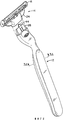
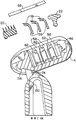
фиг.1 изображает вид в перспективе бритвы согласно изобретению;figure 1 depicts a perspective view of a razor according to the invention;
фиг.2 - вид в перспективе ручки и сменного картриджа бритвы по фиг.1, разделенных один от другого;FIG. 2 is a perspective view of a handle and a replaceable razor cartridge of FIG. 1, separated from one another;
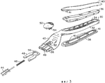
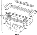
фиг.3 - объемное изображение с пространственным разделением компонентов ручки по фиг.2;figure 3 - volumetric image with a spatial separation of the components of the handle of figure 2;
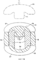
фиг.3А - схематично в разрезе по линии 3А-3А на фиг.2 ручку;figa - schematically in section along the
фиг.4 - объемное изображение с пространственным разделением компонентов сменного картриджа по фиг.2;figure 4 - volumetric image with a spatial separation of the components of the replaceable cartridge of figure 2;
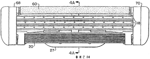
фиг.4А - объемное изображение с пространственным разделением деталей в разрезе по линии 4А-4А на фиг.14 компонентов сменного картриджа;figa is a three-dimensional image with a spatial separation of parts in section along the
фиг.5 - частично в плане опорное устройство картриджа на конце ручки по фиг.2;5 is a partially partially planar support device of the cartridge at the end of the handle of FIG. 2;
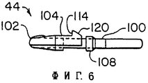
фиг.6 - вертикальную проекцию картриджа ручки по фиг.2;6 is a vertical projection of the cartridge of the handle of figure 2;
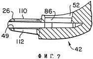
фиг.7 - частичный вид в разрезе по линии 7-7 на фиг.5 опорного устройства картриджа;7 is a partial sectional view taken along line 7-7 of FIG. 5 of the cartridge support device;
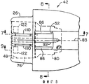
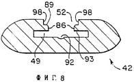
фиг.8 - в разрезе по линии 8-8 на фиг.5 опорное устройство картриджа;Fig. 8 is a sectional view taken along line 8-8 in Fig. 5 of the cartridge support device;
фиг.9 - частичный вид в разрезе по линии 9-9 на фиг.5 опорного устройства картриджа;Fig.9 is a partial view in section along the line 9-9 in Fig.5 of the supporting device of the cartridge;
фиг.10 - вид в плане эжектора, используемого в опорном устройстве картриджа по фиг.5;figure 10 is a view in plan of the ejector used in the supporting device of the cartridge of figure 5;
фиг.11 - вид в перспективе плунжера по фиг.6;11 is a perspective view of the plunger of FIG. 6;
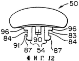
фиг.12 - вертикальную проекцию кнопки эжектора, используемого в опорном устройстве картриджа по фиг.5;12 is a vertical projection of an ejector button used in the cartridge support device of FIG. 5;
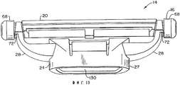
фиг.13 - вертикальную проекцию сменного картриджа по фиг.2;Fig.13 is a vertical projection of a replaceable cartridge of Fig.2;
фиг.14 - вид в плане сменного картриджа по фиг.13;Fig.14 is a plan view of the replaceable cartridge of Fig.13;
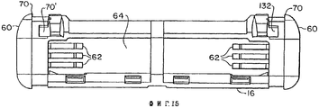
фиг.15 - вид снизу сменного картриджа по фиг.13;Fig. 15 is a bottom view of the replaceable cartridge of Fig. 13;
фиг.16 - вид сбоку, частично с вырывом, показывающий корпус картриджа по фиг.13 в неподпружиненном поворотном положении относительно основания картриджа до присоединения к ручке;Fig.16 is a side view, partially with a pullout, showing the cartridge body of Fig.13 in a non-springy rotary position relative to the base of the cartridge before attaching to the handle;
фиг.17 - вид сбоку, частично с вырывом, картриджа по фиг.13 в подпружиненном положении после присоединения к ручке;Fig.17 is a side view, partially with a gap, of the cartridge of Fig.13 in a spring-loaded position after attaching to the handle;
фиг.18 - вид сбоку, частично с вырывом, изображающий диапазон поворотного движения сменного картриджа по фиг.13;Fig.18 is a side view, partially with a pullout, depicting the range of the rotational movement of the replaceable cartridge of Fig.13;
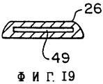
фиг.19 - в разрезе удлинения ручки по фиг.2;Fig.19 is a sectional view of the extension of the handle of Fig.2;
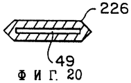
фиг.20 - в разрезе альтернативный пример реализации удлинения ручки по фиг.2;FIG. 20 is a sectional view of an alternative embodiment of the extension of the handle of FIG. 2;
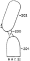
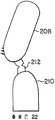
фиг.21 и 22 - сбоку альтернативные примеры реализации картриджей, имеющих различные поворотные устройства.21 and 22 are side views of alternative embodiments of cartridges having various rotary devices.
Ссылаясь на фигуры 1 и 2, бритва 10 включает ручку 12 и сменный бритвенный картридж 14. Как показано в фигуре 2, картридж 14 может сниматься с ручки 12. Картридж 14 включает корпус 16, в котором установлены три лезвия 18, предохранитель 20 и крышку 22. Картридж 14 также включает соединительный элемент 24, на котором установлен с возможностью поворота корпус 16. Соединительный элемент 24 включает основание 27, которое жестко закрепляется с возможностью съема на асимметричном удлинении 26 (фиг.19) на ручке 12, и два рычага 28, которые поддерживают с возможностью поворота корпус 16 с его двух сторон.Referring to figures 1 and 2, the razor 10 includes a
Ссылаясь на фигуру 3, ручка 12 включает пластмассовый элемент 30 металлической окраски в качестве главного структурного элемента, на котором установлены остальные компоненты. Удлиненная часть 32 элемента 30 имеет выемку 34 для размещения металлического (например, из цинка) груза 36, который зажат между пластмассовыми захватными частями 38 и 40 для обеспечения устройства захвата рукой в законченном узле бритвы. Пластмассовые захватные части 38 и 40 выполнены из наружного захватного слоя 37, из эластомерного пластика (например, термопластичного эластомера), и расположенного под ним опорного слоя 39 из неэластомерного пластика (например, акрилотритрилового бутадиенстирола), выполненных двухцветным формованием. Опорный слой из неэластомерной пластмассы имеет удлинения 41, которые запрессованы в груз 36 в удлиненной части 32. Фигура 3А изображает недеформированную форму удлинения 41 (показано штрих-пунктирной линией) и неподвижную посадку этого удлинения на выступах 43.Referring to FIG. 3, the
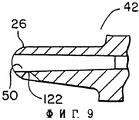
Опорное устройство 42 картриджа проходит от конца удлиненной части 32. Оно включает удлинение 26 в форме трапеции (см.фиг.19) и компоненты, которые обеспечивают подпружиненное воздействие плунжера для подпружинивания корпуса 16 относительно соединительного элемента 24. Оно также включает компоненты, которые обеспечивают выталкивание картриджа 14 из ручки 12.The
Подпружиненный плунжер 44, пружина 46 и U-образный эжектор 48 установлены в выемке 49 опорного устройства 42 картриджа. Кнопка 50 эжектора входит в отверстие 52 на верхней поверхности опорного устройства 42 и имеет нижние консольные части 54, которые входят в прямоугольную выемку 56 в задней узкой части эжектора 48.A spring-loaded
Ссылаясь на фигуры 4, 4А и 15, корпус 16 картриджа 14 имеет пазы 58 в боковых стенках 60 для приема кромок участков основания 59 лезвий 18 и соответствующие упругие рычаги 62 (фиг.15), на которых упруго устанавливается каждое лезвие 18. Лезвия 18 расположены, по существу, в свободном пространстве 64 между боковыми стенками 60 для обеспечения простоты промывания картриджа во время использования.Referring to figures 4, 4A and 15, the
Крышка 22 имеет средство для гладкого бритья и устанавливается в пазу 66 в задней части корпуса 16. Крышка 22 может быть выполнена из материала, содержащего смесь гидрофобного материала и гидрофильного полимерного материала, выщелачиваемого водой, как известно в данной области и описано, например, в патентах США №№5113585 и 5454164, которые включены здесь в качестве ссылочного материала. Предохранитель 20 включает снабженный ребрами эластомерный элемент, установленный впереди корпуса 16 для вхождения в зацепление с кожей пользователя и разглаживания ее; могут быть использованы другие выступы для контакта с кожей, например, как описано в патенте США №5191712, который здесь включается в качестве ссылки. Зажимы 68 крепятся с соответствующих сторон корпуса 16 с внутренней стороны выступающих кромок 70 боковых стенок 60, чтобы удерживать лезвия 18 в корпусе 16 и устанавливать режущие кромки подпружиненных лезвий в нужном положении.The
Зажимы 68 также охватывают нижнюю часть корпуса 16 и предотвращают выход концов 72 поворотной опоры рычагов 28 соединительного элемента 24. Основание 27 имеет отверстие 74 вверху, через которое подпружиненный плунжер 44 ручки проходит, чтобы воздействовать на кулачковую поверхность (не показана на фигуре 4) на нижней части корпуса 16. Основание 27 может иметь изогнутую или скошенную форму.The
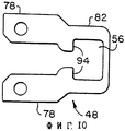
Фигуры 5-12 и 19 изображают детали плунжера 44, эжектор 48, кнопку 50 и опорное устройство 42 картриджа. Как видно на фиг.5, выемка 49 в опорном устройстве 42 картриджа имеет широкую переднюю часть 76 для приема рычагов 78 эжектора 48 (фиг.10) и суженную часть 80 для приема суженной части 82 эжектора 48. Прямоугольная прорезь 56 в более узкой части 82 эжектора 48, по существу, совмещается с отверстием 52 в верхней поверхности опорного устройства 42, хотя прямоугольная прорезь 56 имеет возможность перемещения относительно отверстия 52 вдоль оси 83 скольжения, когда эжектор 48 выталкивается наружу кнопкой 50 эжектора.Figures 5-12 and 19 depict details of a
На фигурах 8 и 12 видно, что каждая консольная часть 54 кнопки 50 эжектора имеет обращенную наружу канавку 84, которая скользит по соответствующей направляющей 86 внутри отверстия 52 вдоль оси 83. Верхние поверхности 83, образующие канавки 84, скользят на верхних поверхностях 89 направляющих 86, а нижние поверхности 91, образующие канавки 84, осуществляют попадание или упор в нижние поверхности 93 направляющей 86. Консольные части 54 кнопки 50 эжектора имеют наклонные поверхности 87, которые взаимодействуют с отогнутыми верхними углами направляющих 86, чтобы отклонять консольные части 54 внутрь, когда кнопка 50 вставляется в опорное устройство 42 картриджа. Когда канавки 84 на консольной части 54 совмещаются с направляющими 86, консольные части 54, по существу, возвращаются в свое неотклоненное положение и фиксируют кнопку 50 эжектора в отверстии 52. Эжектор 48 размещается в углублении 49 перед тем, как вставляется кнопка 50, так что концы консольных частей 54 располагаются внутри прямоугольной прорези 56, чтобы удерживать эжектор 48 в опорном устройстве 42 картриджа. Консольные части 54 упираются в поверхности 94 эжектора 48, когда кнопку 50 эжектора толкают к концу ручки 12. После установки кнопки 50 верхние вертикальные поверхности 96 консольных частей 54 располагаются в пространстве между верхними поверхностями 98 отверстия 52.Figures 8 and 12 show that each
Пружина 46 (фиг.3) проходит через пространство между консольными частями 54 и направляется изогнутой нижней поверхностью направителя 90 на кнопке 50. Как показано в фигуре 8, нижняя поверхность, образующая выемку 49, также имеет вогнутую центральную часть 92 для приема и направления пружины 46.The spring 46 (FIG. 3) passes through the space between the
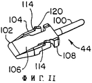
Как показано в фигурах 6 и 11, плунжер 44 имеет плоский корпус 106, цилиндрическое заднее удлинение 100 для размещения пружины 46 (фиг.3), изогнутую переднюю часть кулачкового толкателя 102 для воздействия на кулачковую поверхность 136 (фиг.18) корпуса 16, боковые рычаги 104 и совмещенные задние направляющие части 108. Плоский корпус 106 расположен в плоской передней части выемки 49 (фиг.8). Участки боковых рычагов 104 и совмещенные задние направляющие части 108 выше и ниже корпуса 106 располагаются в пазах 110, 112, расположенных на обеих сторонах асимметричного удлинения 26. Боковые рычаги 104 имеют поверхности упора 114, которые предотвращают движение вперед плунжера 44 за пределы переднего конца паза 110 и 112 (фиг.7). Участки боковых рычагов 104 и направляющие части 108 выше и ниже углубления 49 в пазах 110, 112 действуют как направляющие для направления скользящего действия плунжера 44 вдоль оси 83.As shown in figures 6 and 11, the
Боковые рычаги 104 имеют наклонные поверхности 120 для подпружинивания вниз рычагов 104, когда плунжер 44 вставляется в выемку 49, пока поверхности упора 114 не пройдут за передние концы пазов 110, 112 и поверхности упора 114 не защелкнутся в соответствующем пазу. Так как пазы 110, 112 обеспечены с обеих сторон асимметричного удлинения 26, плунжер 44 может вставляться в любом направлении, причем поверхность упора 114 направлена в пазы 110 и 112.The
На фигурах 5 и 9 показано, что одна поверхность асимметричного удлинения 26 включает углубления 122 для размещения фиксаторов в основании 27 картриджа 14, чтобы удерживать картридж 14 на удлинении 26.Figures 5 and 9 show that one surface of the
При изготовлении ручки 12 компоненты для захвата рукой собираются, начиная с размещения груза 36 в выемке 34, и затем удлинения 41 компонентов 38, 40 запрессовываются в совмещенные отверстия в грузе 36. Груз 36 и компоненты 38, 40 жестко устанавливаются с неподвижной посадкой между удлинениями 41 и выступами 43 и эластомерный слой 37 деформируется, чтобы обеспечить уплотнение между боковыми стенками удлиненной части 32 пластмассового компонента 30 и грузом 36 (Фиг.3А изображает вид недеформированных форм компонентов).In the manufacture of the
При сборке компонентов опорного устройства 42 картриджа в конце ручки 12 сначала в выемку 49 вставляется эжектор 48. Затем вставляются пружина 46 и плунжер 44. Наклонные поверхности 120 боковых рычагов 104 подпружиниваются во время введения в направлении к середине выемки и затем защелкиваются в пазу 110 или 112 (в зависимости от ориентировки плунжера), неподвижно фиксируя плунжер 44, пружину 46 и эжектор 48 в опорном устройстве 42 картриджа. Пружина 46 работает как для подпружинивания эжектора 48 назад к поверхностям выемки 49 и консольным частям 54 кнопки, так и для подпружинивания плунжера 44 вперед, при этом поверхности упора 114 подпружиниваются к передним краям паза 110 или 112. Кнопка 50 вставляется в отверстие 52 после того, как вставляется эжектор 48. Наклонные поверхности 87 подпружиниваются внутрь изогнутыми верхними частями направляющих 86 и кнопка 50 эжектора защелкивается на месте, при этом направляющие 86 располагаются в канавках 84.When assembling the components of the
Фигуры 13-18 изображают другие детали сменного картриджа 14 и его поворотное движение. Ссылаясь на фигуру 13, соединительный элемент 24 показан в собранном виде с корпусом 16, причем концы 72 поворотной опоры удерживаются зажимами 68. Видно, что основание 27 имеет выемку 130 в форме трапеции, которая имеет ту же форму, что и удлинение 26, и сопрягается с удлинением 26.Figures 13-18 depict other details of the
Ссылаясь на фигуру 15, корпус 16, показанный перед тем, как другие компоненты картриджа монтируются на нем, имеет выемки 132, в которые вставляются концы 72 поворотной опоры на концах рычагов 28. Рычаги 28 отклоняются, когда концы 72 вставляются через отверстия к выемкам 132, и затем с силой встают назад в неотклоненное положение после того, как концы 72 располагаются внутри выемок 132 так, что они удерживаются на месте.Referring to FIG. 15, the
Ссылаясь на фигуры 4А и 9, фиксаторы 132 внутри выемки 130 основания 27 сопрягаются с углублениями 122 асимметричного удлинения 26. Вверху выемки 130 находится отверстие 74, которое позволяет подпружиненному плунжеру 44 проходить через основание 27 и взаимодействовать с поверхностью 136 в нижней части корпуса 16.Referring to figures 4A and 9, the
На фигурах 16-18 видно, что каждый конец 72 поворотной опоры имеет нижнюю изогнутую поверхность 138, которая скользит на верхней изогнутой поверхности 140 корпуса 16, обеспечивая ось поворота в центре круга, который включает поверхность 140. Ось поворота, таким образом, находится впереди лезвий в районе предохранителя 20. Фиг.16 показывает корпус 16 в неподпружиненном положении, в котором концы 72 поворотной опоры поддерживают переднюю поверхность направляющей стенки 162. Фиг.17 показывает подпружиненное вперед положение корпуса 16, когда передняя поверхность концов 72 толкается к участку передней стенки корпуса 16. Это нерабочее положение корпуса 16 до бритья. Подпружиненное вперед нерабочее положение достигается выполнением кулачковой поверхности 136 так, чтобы плунжер 44, имеющий поверхность кулачкового толкателя 102, занимал нерабочее положение около передней части корпуса 16, как показано в фигуре 18.In figures 16-18 it is seen that each
Фиг.18 показывает диапазон поворотного движения корпуса 16. Во время бритья крышка 22 будет сначала входить в контакт с кожей пользователя, а корпус 16 будет поворачиваться по часовой стрелке и, по существу, следовать за контурами лица пользователя будучи подпружиненным плунжером 44. Первоначальная ориентация вверх крышки сначала заставит толкать лезвие, ближнее к крышке 22, сильнее к коже пользователя, чем лезвия, которые ближе к предохранителю. Однако поворот в участке предохранителя и легкое возвратное усилие заставляет картридж распределять нагрузку во время бритья так, что большая нагрузка приходится на предохранитель, а не на крышку. Три лезвия имеют изначально возможность постепенно открываться (выдвигаться), что определяется перпендикулярным расстоянием или высотой кромки лезвия, измеряемой относительно плоскости, тангенциальной к поверхностям компонентов картриджа, входящих в контакт с кожей, непосредственно впереди или сзади каждого лезвия. В частности, первое лезвие имеет отрицательную степень выдвижения, второе лезвие имеет нулевую степень выдвижения, а третье лезвие имеет положительную степень выдвижения. Пружинные постоянные и заданные нагрузки для лезвий те же самые, и лезвия имеют распределения «постепенного усилия» во время бритья, то есть усилие, прикладываемое к третьему лезвию, превышает усилие на первое лезвие, а усилие, прикладываемое ко второму лезвию, является промежуточным между усилиями на первое и второе лезвия или равно усилию либо первого, либо третьего лезвия. Считается, что такое постепенное распределение усилий дает успешные результаты при бритье картриджами с тремя упруго установленными лезвиями.Fig. 18 shows the range of pivot movement of the
Другие примеры реализации изобретения входят в объем прилагаемых пунктов патентования. Основание может удерживаться на корпусе с помощью размыкаемой задвижки. Лезвия могут загружаться снизу, а не сверху. Опорное устройство картриджа может быть выполнено как узел, отдельный от ручки и крепящийся к ней. Вместо трапециеобразного удлинения 26 (фиг.19) может использоваться шестигранное удлинение 226 (фиг.20) или может использоваться другая асимметричная форма.Other examples of implementation of the invention are included in the scope of the attached patent claims. The base can be held on the body using a shut-off valve. Blades can be loaded from below rather than from above. The support device of the cartridge can be made as a unit separate from the handle and attached to it. Instead of a trapezoidal extension 26 (FIG. 19), a hexagonal extension 226 (FIG. 20) may be used or another asymmetric shape may be used.
Поворотное соединение может быть обеспечено осями в соответствующих отверстиях, гильзовыми подшипниками и т.д. Например, ссылаясь на фиг.21, поворотное опорное устройство может быть обеспечено шарниром 200 из гибкого пластика, который выполнен из материала, более гибкого, чем корпус 202, и соединяет корпус и соединительный элемент 204 в районе поворота 206; эти компоненты могут быть выполнены двухцветным формованием. В качестве альтернативы, ссылаясь на фигуру 22, корпус 208 и соединительный элемент 210 могут быть выполнены из одного куска пластмассы, а поворотное опорное устройство может быть обеспечено подвижным шарниром 212. Подвижный шарнир может быть выполнен с корпусами и соединять между собой элементы из различных пластмасс.A swivel joint can be provided with axles in the corresponding holes, sleeve bearings, etc. For example, referring to FIG. 21, the pivot support device may be provided with a
Claims (40)
Applications Claiming Priority (3)
| Application Number | Priority Date | Filing Date | Title |
|---|---|---|---|
| US08/630,437 US5787586A (en) | 1996-04-10 | 1996-04-10 | Shaving system and method |
| US08/630,437 | 1996-04-10 | ||
| US08/630437 | 1996-04-10 |
Related Parent Applications (1)
| Application Number | Title | Priority Date | Filing Date |
|---|---|---|---|
| RU98120350/12A Division RU2214903C2 (en) | 1996-04-10 | 1997-04-08 | Shaver (variants) |
Publications (2)
| Publication Number | Publication Date |
|---|---|
| RU2002122571A RU2002122571A (en) | 2004-03-20 |
| RU2263024C2 true RU2263024C2 (en) | 2005-10-27 |
Family
ID=24527162
Family Applications (4)
| Application Number | Title | Priority Date | Filing Date |
|---|---|---|---|
| RU98120350/12A RU2214903C2 (en) | 1996-04-10 | 1997-04-08 | Shaver (variants) |
| RU2002122570/12A RU2263022C2 (en) | 1996-04-10 | 1997-04-08 | Changeable razor cartridge |
| RU2002122571/12A RU2263024C2 (en) | 1996-04-10 | 1997-04-08 | Razor handle and rod for razor handle |
| RU2002122569/12A RU2263023C2 (en) | 1996-04-10 | 1997-04-08 | Method of making detachable cartridge and handle for razor |
Family Applications Before (2)
| Application Number | Title | Priority Date | Filing Date |
|---|---|---|---|
| RU98120350/12A RU2214903C2 (en) | 1996-04-10 | 1997-04-08 | Shaver (variants) |
| RU2002122570/12A RU2263022C2 (en) | 1996-04-10 | 1997-04-08 | Changeable razor cartridge |
Family Applications After (1)
| Application Number | Title | Priority Date | Filing Date |
|---|---|---|---|
| RU2002122569/12A RU2263023C2 (en) | 1996-04-10 | 1997-04-08 | Method of making detachable cartridge and handle for razor |
Country Status (35)
| Country | Link |
|---|---|
| US (6) | US5787586A (en) |
| EP (7) | EP1407862B1 (en) |
| JP (5) | JP4166279B2 (en) |
| KR (4) | KR100538755B1 (en) |
| CN (1) | CN1101746C (en) |
| AR (1) | AR006556A1 (en) |
| AT (7) | ATE317747T1 (en) |
| AU (1) | AU734685B2 (en) |
| BR (1) | BR9708631A (en) |
| CA (4) | CA2429132C (en) |
| CO (1) | CO4700321A1 (en) |
| CZ (3) | CZ297018B6 (en) |
| DE (10) | DE69735246T2 (en) |
| DK (6) | DK1226906T4 (en) |
| EG (1) | EG22076A (en) |
| ES (7) | ES2218478T5 (en) |
| GR (1) | GR3036054T3 (en) |
| HK (6) | HK1015729A1 (en) |
| HU (3) | HU223282B1 (en) |
| ID (1) | ID16583A (en) |
| IL (5) | IL126354A (en) |
| MY (5) | MY125601A (en) |
| NO (3) | NO323067B1 (en) |
| NZ (2) | NZ504330A (en) |
| PL (1) | PL185191B1 (en) |
| PT (6) | PT1226905E (en) |
| RO (1) | RO121331B1 (en) |
| RS (6) | RS49547B (en) |
| RU (4) | RU2214903C2 (en) |
| SK (3) | SK286638B6 (en) |
| TR (3) | TR200002198T2 (en) |
| TW (1) | TW375561B (en) |
| UA (1) | UA63904C2 (en) |
| WO (1) | WO1997037819A2 (en) |
| ZA (1) | ZA972946B (en) |
Families Citing this family (275)
| Publication number | Priority date | Publication date | Assignee | Title |
|---|---|---|---|---|
| ES2299951T3 (en) * | 1991-11-27 | 2008-06-01 | The Gillette Company | RAZORS. |
| US5787586A (en) * | 1996-04-10 | 1998-08-04 | The Gillette Company | Shaving system and method |
| US6041926A (en) * | 1996-04-10 | 2000-03-28 | The Gillette Company | Dispensing razor blade cartridges used with a handle |
| US6085426A (en) * | 1996-04-10 | 2000-07-11 | The Gillette Company | Dispensing razor blade cartridges used with a handle |
| US5956851A (en) * | 1996-04-10 | 1999-09-28 | The Gillette Company | Shaving system including handle and replaceable cartridges |
| US5956848A (en) | 1997-02-27 | 1999-09-28 | The Gillette Company | Shaving system |
| US6035537A (en) * | 1997-09-30 | 2000-03-14 | The Gillette Company | Razor cartridge with metal clip retaining blades |
| US6009624A (en) * | 1997-09-30 | 2000-01-04 | The Gillette Company | Razor cartridge with movable blades |
| US6161287A (en) | 1998-04-24 | 2000-12-19 | The Gillette Company | Razor blade system |
| CA2267729A1 (en) * | 1998-09-14 | 2000-03-14 | Warner-Lambert Company | Razor frame with integral weight |
| GB9903415D0 (en) * | 1999-02-15 | 1999-04-07 | Gillette Co | Safety razors |
| US6112412A (en) * | 1999-04-21 | 2000-09-05 | Warner-Lambert Company | Razor assembly and cartridge having improved wash-through |
| US6772523B1 (en) | 1999-04-21 | 2004-08-10 | Eveready Battery Company, Inc. | Pivotable and flexible razor assembly and cartridge |
| US6182366B1 (en) | 1999-04-21 | 2001-02-06 | Warner-Lambert Company | Flexible razor assembly and cartridge |
| US6138361A (en) * | 1999-04-21 | 2000-10-31 | Warner-Lambert Company | Pivotable razor assembly and cartridge |
| US6223442B1 (en) * | 1999-08-19 | 2001-05-01 | William Alvarez Pina | Non-motorized razor with spring-supported head |
| GB2354474B8 (en) | 1999-09-27 | 2008-01-29 | Gillette Co | Safety razors |
| USD425251S (en) * | 1999-10-13 | 2000-05-16 | The Gillette Company | Razor handle |
| USD425250S (en) * | 1999-10-13 | 2000-05-16 | The Gillette Company | Razor handle |
| US6276367B1 (en) | 2000-02-22 | 2001-08-21 | Andrey Piatetsky | Liquid-reservoir hairbrush |
| US6675479B1 (en) * | 2000-02-29 | 2004-01-13 | The Gillette Company | Shaving razor and blade unit with improved guard |
| US6684513B1 (en) * | 2000-02-29 | 2004-02-03 | The Gillette Company | Razor blade technology |
| US6651342B1 (en) | 2000-02-29 | 2003-11-25 | The Gillette Company | Shaving razor and blade unit with improved guard |
| US6266888B1 (en) * | 2000-03-15 | 2001-07-31 | Thomas E. Zowaski | Reaching razor |
| US6349471B1 (en) * | 2000-07-19 | 2002-02-26 | The Gillette Company | Razor cartridge with painted and drawn retaining clip |
| US20180036895A1 (en) * | 2000-11-01 | 2018-02-08 | Sharidan L. Stiles | Snap on and off multi-size interchangeable blade cartridges with handle |
| US6916035B2 (en) | 2001-01-23 | 2005-07-12 | Russell A. Houser | Athletic devices and other devices with superelastic components |
| US20020116831A1 (en) | 2001-02-28 | 2002-08-29 | Coffin David C. | Apparatus for releasably retaining a disposable razor cartridge |
| US7160508B2 (en) * | 2001-09-05 | 2007-01-09 | The Gillette Company | Personal care products having elastomeric portions |
| JP3833171B2 (en) * | 2001-12-21 | 2006-10-11 | ファイザー・プロダクツ・インク | Razor device |
| US7152512B1 (en) | 2002-04-18 | 2006-12-26 | American Safety Razor | Razor handle with spring fingers |
| US20040055159A1 (en) * | 2002-09-20 | 2004-03-25 | Jeff Khomari | V-shaped razor |
| US20040055156A1 (en) * | 2002-09-25 | 2004-03-25 | The Gillette Company | Safety razor |
| AU2004218016A1 (en) * | 2003-02-28 | 2004-09-16 | Eveready Battery Company, Inc. | Shaving implement having improved pivot axis location |
| US20040172832A1 (en) * | 2003-03-04 | 2004-09-09 | Colin Clipstone | Razor blade |
| US20040181943A1 (en) * | 2003-03-18 | 2004-09-23 | Michael Kwiecien | Shaving systems |
| DE10327739B4 (en) * | 2003-06-18 | 2006-06-08 | Feintechnik Gmbh Eisfeld | Razor blade unit for a razor |
| GB2406537B (en) | 2003-07-21 | 2006-09-06 | Gillette Co | Safety razors |
| US7617607B2 (en) * | 2003-07-21 | 2009-11-17 | The Gillette Company | Shaving razors and other hair cutting assemblies |
| GB0326646D0 (en) | 2003-11-14 | 2003-12-17 | Gillette Co | Safety razors |
| GB2408010B (en) * | 2003-11-17 | 2007-03-28 | Knowledge & Merchandising Inc | Shaving product |
| US7367125B2 (en) | 2003-12-10 | 2008-05-06 | The Gillette Company | Shaving systems |
| WO2005072918A1 (en) * | 2004-01-26 | 2005-08-11 | Koninklijke Philips Electronics N.V. | A safety razor apparatus having a pivotable grip portion |
| US7272991B2 (en) * | 2004-02-09 | 2007-09-25 | The Gillette Company | Shaving razors, and blade subassemblies therefor and methods of manufacture |
| US7131202B2 (en) * | 2004-03-11 | 2006-11-07 | The Gillette Company | Cutting members for shaving razors with multiple blades |
| US20050198825A1 (en) * | 2004-03-11 | 2005-09-15 | Apprille Domenic V.Jr. | Dispensers for razor blade cartridges |
| US20050198830A1 (en) * | 2004-03-11 | 2005-09-15 | Walker Vincent P. | Shaving cartridges and razors |
| US7168173B2 (en) | 2004-03-11 | 2007-01-30 | The Gillette Company | Shaving system |
| US7690122B2 (en) * | 2004-03-11 | 2010-04-06 | The Gillette Company | Shaving razor with button |
| US20050198829A1 (en) * | 2004-03-11 | 2005-09-15 | Gray Michael J. | Shaving razor with trimming blade |
| US7197825B2 (en) * | 2004-03-11 | 2007-04-03 | The Gillette Company | Razors and shaving cartridges with guard |
| US8104184B2 (en) * | 2004-03-11 | 2012-01-31 | The Gillette Company | Shaving cartridges and razors |
| US7669335B2 (en) | 2004-03-11 | 2010-03-02 | The Gillette Company | Shaving razors and shaving cartridges |
| DE202005021798U1 (en) | 2004-03-11 | 2010-03-18 | The Gillette Co., Boston | Razors and other hair cutting devices |
| US7536787B2 (en) * | 2004-03-30 | 2009-05-26 | Ridgewood Industries Llc | Wet razor and electric trimmer assembly |
| US7673541B2 (en) * | 2004-06-03 | 2010-03-09 | The Gillette Company | Colored razor blades |
| US8033023B2 (en) * | 2004-10-20 | 2011-10-11 | The Gillette Company | Shaving razors and cartridges |
| US7284461B2 (en) * | 2004-12-16 | 2007-10-23 | The Gillette Company | Colored razor blades |
| KR100637428B1 (en) * | 2004-12-17 | 2006-10-24 | 박혜산 | A cutting instrument for curing hair |
| CA2596780A1 (en) | 2005-02-03 | 2006-08-10 | Bic-Violex Sa | Razor handle having an arcuate profile |
| EP1843878B1 (en) * | 2005-02-03 | 2010-04-07 | BIC Violex S.A. | Razor handle having an air cushion finger rest area |
| CA2596785A1 (en) * | 2005-02-03 | 2006-08-10 | Bic-Violex Sa | Razor handle having converging side surfaces |
| CA2596795A1 (en) | 2005-02-03 | 2006-08-10 | Bic-Violex Sa | Razor handle having ergonomic gripping areas |
| BRPI0519867B1 (en) | 2005-02-03 | 2019-03-19 | Bic-Violex Sa | Shaving Cord |
| CA2596771A1 (en) * | 2005-02-03 | 2006-08-10 | Bic-Violex Sa | Razor handle having a reticulated head portion |
| US7219430B2 (en) * | 2005-03-08 | 2007-05-22 | The Gillette Company | Oscillating razors |
| US20060277767A1 (en) * | 2005-06-14 | 2006-12-14 | Shuwei Sun | Razor blades |
| EP1896225B1 (en) * | 2005-06-28 | 2011-03-30 | BIC Violex S.A. | Razor handle provided with an improved grip |
| WO2007000185A1 (en) * | 2005-06-28 | 2007-01-04 | Bic-Violex Sa | Ergonomic razor handle provided with an improved grip |
| US8256532B2 (en) * | 2005-07-01 | 2012-09-04 | Board Of Regents, The University Of Texas System | System, program products, and methods for controlling drilling fluid parameters |
| US20070056167A1 (en) * | 2005-09-14 | 2007-03-15 | Eveready Battery Company, Inc. | Blade mounting members for a razor cartridge |
| US20070124944A1 (en) * | 2005-11-30 | 2007-06-07 | Eveready Battery Company, Inc. | Razor blade and method of making it |
| US20070131060A1 (en) * | 2005-12-14 | 2007-06-14 | The Gillette Company | Automated control of razor blade colorization |
| CN101384205B (en) | 2006-02-13 | 2012-12-12 | 布莱克和戴克尔公司 | Power mop with exposable scrub brush |
| US20070270242A1 (en) * | 2006-05-17 | 2007-11-22 | Callaway Golf Company | Polybutadiene diols for unique polyurethane |
| US20080086888A1 (en) * | 2006-10-11 | 2008-04-17 | Noah Scheinfeld | Razor blades comprising a layer including releasable bioactive agent |
| US20080086899A1 (en) * | 2006-10-12 | 2008-04-17 | Gallagher Richard N | Razor head and method for making the same |
| WO2008051109A1 (en) * | 2006-10-26 | 2008-05-02 | Vladimir Anatolievich Urvanov | Razor |
| JP5247715B2 (en) * | 2006-11-20 | 2013-07-24 | コーニンクレッカ フィリップス エレクトロニクス エヌ ヴィ | Rotary shaver with improved support structure for shaving head |
| JP5220768B2 (en) * | 2007-02-01 | 2013-06-26 | エバレデイ バツテリ カンパニー インコーポレーテツド | Laser handle |
| BRPI0808545B1 (en) * | 2007-03-02 | 2019-06-04 | The Gillette Company | SHAVING OR DEPILATING DEVICE HAVING AN ALCOHOL FOR SHAVING OR DEPILATION WITH A CONTOUR IN ASA |
| US20080256801A1 (en) * | 2007-04-20 | 2008-10-23 | O'connor William Thomas | Razor cartridge with front pivot axis |
| US20080256803A1 (en) | 2007-04-20 | 2008-10-23 | William Earle Tucker | Razor cartridge pivot axis |
| US9517570B2 (en) | 2007-04-20 | 2016-12-13 | The Gillette Company | Razor cartridge |
| JP5350370B2 (en) * | 2007-06-12 | 2013-11-27 | ザ ジレット カンパニー | Manual liquid dispensing razor |
| US8438736B2 (en) * | 2007-08-24 | 2013-05-14 | The Gillette Company | Safety razor with improved guard |
| US7770294B2 (en) * | 2007-08-30 | 2010-08-10 | The Gillette Company | Razor with blade unit biasing member |
| US7871347B2 (en) | 2007-10-11 | 2011-01-18 | Shimano Inc. | Bicycle rear sprocket assembly |
| DE102007050381A1 (en) † | 2007-10-22 | 2009-04-23 | Braun Gmbh | Hair removal device |
| DE102007050661A1 (en) * | 2007-10-24 | 2009-04-30 | Braun Gmbh | epilator |
| US8435433B2 (en) * | 2008-02-04 | 2013-05-07 | The Gillette Company | Method for making a handle for a personal grooming device |
| CN101965252A (en) * | 2008-02-27 | 2011-02-02 | 美国安全剃刀公司 | Shaving system |
| US20090255124A1 (en) * | 2008-04-11 | 2009-10-15 | Hassam Hasbani | Cartridge for a Shaving Razor |
| ATE517722T1 (en) * | 2008-05-23 | 2011-08-15 | Feintechnik Gmbh Eisfeld | RAZOR BLADE UNIT WITH FILM HINGE |
| US20090293292A1 (en) * | 2008-05-27 | 2009-12-03 | Christopher Ramm | Resilient razor handle |
| US20100005669A1 (en) * | 2008-07-14 | 2010-01-14 | Florina Winter | Razor Handle |
| US8205344B2 (en) | 2008-08-20 | 2012-06-26 | The Gillette Company | Safety razor having pivotable blade unit |
| US8151468B2 (en) * | 2008-09-26 | 2012-04-10 | The Gillette Company | Handle for shaving razors having improved grip |
| AU2009296283A1 (en) | 2008-09-29 | 2010-04-01 | The Gillette Company | Razor cartridges with perforated blade assemblies |
| JP5052473B2 (en) * | 2008-09-30 | 2012-10-17 | ノーレッジ・アンド・マーチャンダイジング・インコーポレーテッド・リミテッド | Razor |
| US7913393B2 (en) | 2008-10-07 | 2011-03-29 | The Gillette Company | Safety razor with multi-pivot blade unit |
| US8671577B2 (en) * | 2008-12-03 | 2014-03-18 | Thomas A. Brown | Razor with independent suspension |
| RU2008150012A (en) * | 2008-12-10 | 2010-06-20 | Александр Тарасович Володин (RU) | SAFETY RAZOR BLADE BLOCK |
| SG172834A1 (en) * | 2009-01-05 | 2011-08-29 | Gillette Co | Docking mechanisms for shaving razors and cartridges |
| US8745877B2 (en) | 2009-03-23 | 2014-06-10 | The Gillette Company | Manually actuable liquid dispensing razor |
| US8826543B2 (en) | 2009-03-23 | 2014-09-09 | The Gillette Company | Manually actuable liquid dispensing razor |
| USD625882S1 (en) | 2009-05-21 | 2010-10-19 | American Safety Razor | Shaving razor |
| US20110016724A1 (en) | 2009-07-24 | 2011-01-27 | Matthew Frank Murgida | Resilient Skin Contacting Members to Facilitate Pivoting |
| US8273205B2 (en) | 2009-07-24 | 2012-09-25 | The Gillette Company | Manufacture of pivoting resilient skin contacting members |
| CN201446542U (en) * | 2009-08-06 | 2010-05-05 | 任向荣 | Razor head and outer frame body |
| US20110088269A1 (en) * | 2009-10-21 | 2011-04-21 | Walker Jr Vincent Paul | Docking Mechanisms for Shaving Razors and Cartridges |
| USD640414S1 (en) | 2009-11-30 | 2011-06-21 | American Safety Razor | Shaving razor |
| USD633252S1 (en) | 2009-11-30 | 2011-02-22 | American Safety Razor | Shaving razor |
| USD640004S1 (en) | 2009-11-30 | 2011-06-14 | American Safety Razor | Shaving razor |
| WO2011075505A1 (en) * | 2009-12-18 | 2011-06-23 | The Gillette Company | Razor cartridge with non-cutting element |
| US8793880B2 (en) | 2010-02-16 | 2014-08-05 | The Gillette Company | Shaving razor adapter attaching a shaving razor cartridge to a shaving razor handle |
| US20110203120A1 (en) * | 2010-02-23 | 2011-08-25 | Stephen Charles Witkus | Razor cartridge assembly |
| US20110219624A1 (en) | 2010-03-15 | 2011-09-15 | Barry Keith Rockell | Liquid Dispensing Device Comprising A Peristaltic Pump |
| CA2793461A1 (en) | 2010-03-15 | 2011-09-22 | The Gillette Company | Hair removal device |
| EP2366507B1 (en) | 2010-03-15 | 2015-05-13 | The Gillette Company | Razor cartridge |
| US20110247217A1 (en) * | 2010-04-12 | 2011-10-13 | Robert Harold Johnson | Shaving cartridge having a front pivoting hood with a biasing member |
| USD636533S1 (en) | 2010-05-11 | 2011-04-19 | American Safety Razor | Razor handle |
| USD635718S1 (en) | 2010-05-12 | 2011-04-05 | American Safety Razor | Razor handle |
| USD636938S1 (en) | 2010-05-12 | 2011-04-26 | American Safety Razor | Razor handle |
| US8931176B2 (en) * | 2010-06-09 | 2015-01-13 | The Gillette Company | Blade cartridge guard comprising an array of flexible fins extending in multiple directions |
| USD633253S1 (en) | 2010-06-23 | 2011-02-22 | American Safety Razor | Razor cartridge |
| EP2588282B1 (en) | 2010-06-29 | 2019-04-24 | Edgewell Personal Care Brands, LLC | Razor handle |
| USD648075S1 (en) | 2010-07-07 | 2011-11-01 | American Safety Razor | Razor cartridge |
| USD640415S1 (en) | 2010-07-07 | 2011-06-21 | American Safety Razor | Razor cartridge |
| JP5669473B2 (en) * | 2010-07-27 | 2015-02-12 | 株式会社貝印刃物開発センター | Razor handle |
| US8745882B2 (en) | 2010-09-29 | 2014-06-10 | The Gillette Company | Flexible and separable portion of a razor handle |
| US8745883B2 (en) | 2010-09-29 | 2014-06-10 | The Gillette Company | Razor handle with a rotatable portion |
| USD643976S1 (en) | 2010-10-19 | 2011-08-23 | American Safety Razor | Razor cartridge |
| USD643977S1 (en) | 2010-10-19 | 2011-08-23 | American Safety Razor | Razor cartridge |
| US8769825B2 (en) * | 2010-10-20 | 2014-07-08 | The Gillette Company | Shaving razor including a biasing member producing a progressively increasing cartridge return torque and handle geometry enhancing control during shaving |
| US8650763B2 (en) | 2010-10-20 | 2014-02-18 | The Gillette Company | Shaving razor providing enhanced control during shaving |
| MX2013004696A (en) | 2010-10-27 | 2013-06-12 | Gillette Co | Composition dispensing device comprising a non-foaming hydrating composition. |
| CN102452095B (en) * | 2010-10-28 | 2014-10-29 | 吉列公司 | Applicator of hair removing device for distributing liquid |
| US9073226B2 (en) | 2011-02-09 | 2015-07-07 | The Gillette Company | Pivoting razor |
| BR112013010501A2 (en) | 2011-02-28 | 2016-07-05 | Gillette Co | shaving or shaving apparatus comprising a molded shaving or shaving aid composition comprising a pyrithione source |
| WO2012170882A1 (en) * | 2011-06-08 | 2012-12-13 | Zafirro, Llc | Mineral blade and razor for use with same |
| US9101471B2 (en) | 2011-06-13 | 2015-08-11 | Edwards Lifesciences Corporation | Systems and delivery handles for delivering prosthetic heart valves disposed on valve holders |
| BR112014003344A2 (en) | 2011-08-16 | 2017-01-17 | Gillette Co | composition dispensing device comprising a wetting composition |
| US9561596B2 (en) * | 2011-09-19 | 2017-02-07 | Wahl Clipper Corporation | Multi-part hair clipper housing lid |
| US20130145625A1 (en) * | 2011-12-09 | 2013-06-13 | Xiaolan Xu | Fluid dispensing shaving razor |
| US20130160307A1 (en) | 2011-12-22 | 2013-06-27 | Daren Mark Howell | Razor cartridge that rotates about a virtual pivot axis |
| US9193079B2 (en) | 2011-12-22 | 2015-11-24 | The Gillette Company | Linkage mechanism for a razor |
| US20130160306A1 (en) | 2011-12-22 | 2013-06-27 | Daren Mark Howell | Linkage mechanism producing a virtual pivot axis for a razor |
| USD665948S1 (en) | 2012-01-10 | 2012-08-21 | The Gillette Company | Hair removal cartridge |
| EP4166289A1 (en) | 2012-01-12 | 2023-04-19 | Spectrum Brands, Inc. | Electric hair trimmer |
| US9032631B2 (en) | 2012-03-28 | 2015-05-19 | The Gillette Company | Indicia for razor with a rotatable portion |
| US8938885B2 (en) | 2012-05-01 | 2015-01-27 | The Gillette Company | Razor handle with a rotatable portion |
| US8789282B2 (en) | 2012-05-25 | 2014-07-29 | Shavelogic, Inc. | Magnetic attachment for shaving cartridge |
| US10272579B2 (en) | 2012-05-25 | 2019-04-30 | Shavelogic, Inc. | Magnetic attachment for shaving cartridge |
| US20140000114A1 (en) * | 2012-06-28 | 2014-01-02 | The Gillette Company | Shaving razor cartridge |
| US9283685B2 (en) | 2012-07-26 | 2016-03-15 | Shavelogic, Inc. | Pivoting razors |
| KR101991472B1 (en) * | 2012-09-26 | 2019-09-30 | 빅-비올렉스 에스아 | Method and system for the manufacture of a razor cartridge |
| US9486930B2 (en) | 2012-09-27 | 2016-11-08 | Shavelogic, Inc. | Shaving systems |
| WO2014051842A1 (en) | 2012-09-27 | 2014-04-03 | Shavelogic, Inc. | Shaving systems |
| WO2014051843A1 (en) | 2012-09-28 | 2014-04-03 | Shavelogic, Inc. | Shaving systems |
| US20140116211A1 (en) | 2012-10-25 | 2014-05-01 | Shavelogic, Inc. | Dedicated Attachment Systems for Consumer Products |
| US9623575B2 (en) | 2012-12-18 | 2017-04-18 | Shavelogic, Inc. | Shaving systems |
| WO2014094908A1 (en) * | 2012-12-21 | 2014-06-26 | Bic-Violex Sa | Shaver |
| JP6053955B2 (en) * | 2012-12-21 | 2016-12-27 | ビック・バイオレクス・エス・エー | Shaver with replaceable cartridge, cartridge and head handle assembly for such a shaver |
| KR101977754B1 (en) * | 2012-12-21 | 2019-05-13 | 빅-비올렉스 에스아 | Shaver with interchangeable cartridge, cartridge and head and handle assembly for such shaver |
| US20140230256A1 (en) * | 2013-02-20 | 2014-08-21 | The Gillette Company | Hand held device |
| SG11201506746UA (en) | 2013-03-04 | 2015-09-29 | Gillette Co | Article for carrying a glide member for use with a razor |
| MX2015011597A (en) | 2013-03-04 | 2015-12-09 | Gillette Co | Article for carrying a glide member for use with a razor. |
| EP2964432B1 (en) | 2013-03-04 | 2018-08-29 | The Gillette Company LLC | Razor with two glide members pivoting about a single axis |
| CA2915034A1 (en) | 2013-06-17 | 2014-12-24 | The Gillette Company | A glide member comprising low to no hygroscopic components for use with a razor |
| USD737513S1 (en) * | 2013-08-26 | 2015-08-25 | The Gillette Company | Razor component |
| US10441307B2 (en) | 2013-09-09 | 2019-10-15 | Dd Karma Llc | Hand held dermaplaning device and dermaplaning process |
| CN105705104A (en) | 2013-09-09 | 2016-06-22 | 迪迪卡玛有限责任公司 | Hand held dermaplaning device and dermaplaning process |
| EP2853362B1 (en) * | 2013-09-25 | 2016-08-10 | BIC Violex S.A. | A shaving blade cartridge |
| SG11201602439RA (en) | 2013-11-01 | 2016-04-28 | Gillette Co | Shave care composition for a liquid dispensing razor |
| US9321182B2 (en) * | 2013-11-01 | 2016-04-26 | The Gillette Company | Razor cartridge for a liquid dispensing razor |
| US9216514B2 (en) | 2013-11-01 | 2015-12-22 | The Gillette Company | Manually actuatable liquid dispensing razor |
| US20150158192A1 (en) | 2013-12-09 | 2015-06-11 | Shavelogic, Inc. | Multi-material pivot return for shaving systems |
| KR102138291B1 (en) | 2013-12-18 | 2020-07-28 | 빅-비올렉스 에스아 | A shaving blade cartridge |
| US20150174775A1 (en) | 2013-12-20 | 2015-06-25 | The Gillette Company | Pivoting shaving razor handle |
| US9707690B2 (en) * | 2013-12-20 | 2017-07-18 | The Gillette Company Llc | Heated shaving razor handle |
| US10486320B2 (en) | 2014-01-02 | 2019-11-26 | Andrea Molinari | Device for supporting razor blades |
| EP2902156B1 (en) | 2014-01-31 | 2017-11-22 | Feintechnik GmbH Eisfeld | Shaver with a handle and a rotatable cutting unit |
| MX2016011188A (en) * | 2014-02-27 | 2016-12-16 | Bic Violex Sa | A shaving blade cartridge, a shaver comprising such shaving blade cartridge and a method of manufacturing such a shaving blade cartridge. |
| JP2017510335A (en) * | 2014-02-28 | 2017-04-13 | ビック・バイオレクス・エス・エー | Razor handle with an insert in the hole and a razor with such a razor handle |
| USD850721S1 (en) | 2014-03-05 | 2019-06-04 | Mack-Ray, Inc. | Razor cartridge |
| AU2015227141B2 (en) | 2014-03-05 | 2019-07-18 | Mack-Ray, Inc. | Dual sided razor |
| US9616584B2 (en) * | 2014-03-20 | 2017-04-11 | Rolling Razor, Inc. | Shaving razor and shaving handle with an interconnection mechanism |
| US11325270B2 (en) | 2014-03-21 | 2022-05-10 | Sl Ip Company Llc | Metal spring return and method |
| US20150266191A1 (en) * | 2014-03-24 | 2015-09-24 | Michael J. MAIMONE | Razor with handle having articulable joint |
| US11148310B2 (en) | 2014-03-24 | 2021-10-19 | Flexhandle, L.L.C. | Razor with handle having articulable joint |
| US20150273711A1 (en) | 2014-03-26 | 2015-10-01 | The Gillette Company | Razor Comprising A Molded Shaving Aid Composition Comprising A Thermally Resilient Sensate |
| RU2660546C2 (en) * | 2014-04-16 | 2018-07-06 | Бик-Виолекс Са | Shaver handles to be releasable connected to shaving cartridges |
| CN103950047B (en) * | 2014-04-29 | 2016-06-29 | 任向荣 | Shaver and shaver assemble method |
| US20160008994A1 (en) * | 2014-07-11 | 2016-01-14 | Alvincent JOHNSON | Ergonomic hair cutting tools |
| BR112017000281B1 (en) * | 2014-07-11 | 2021-06-01 | Shavelogic Inc | SHAVING CARTRIDGE |
| MX2017001590A (en) * | 2014-08-04 | 2017-05-04 | Bic Violex Sa | A razor handle comprising an insert within a hole and razor comprising such a razor handle. |
| RU2672119C2 (en) * | 2014-08-07 | 2018-11-12 | Бик-Виолекс Са | Razor handle comprising element within cavity thereof and razor comprising such razor handle |
| CN207014413U (en) * | 2014-09-12 | 2018-02-16 | 沙夫罗吉克公司 | Shave razor |
| AU2015330925B2 (en) * | 2014-10-10 | 2019-08-15 | Edgewell Personal Care Brands, Llc | Universal razor cartridge handle |
| AU2015332483B2 (en) | 2014-10-15 | 2019-08-15 | Edgewell Personal Care Brands, Llc | Razor cartridge connector |
| USD749264S1 (en) | 2014-11-24 | 2016-02-09 | Edgewell Personal Care Brands, Llc | Safety razor |
| USD749267S1 (en) | 2014-11-24 | 2016-02-09 | EdgewellPersonal Care Brands, LLC | Safety razor handle |
| CA2969035C (en) | 2014-12-05 | 2021-01-19 | Bic-Violex Sa | A shaver's handle with a lock and release mechanism for engaging and disengaging a razor cartridge |
| AU2016211182B2 (en) * | 2015-02-01 | 2021-05-06 | Mack-Ray, Inc. | Dual sided razor |
| CN104669318B (en) * | 2015-02-03 | 2017-01-04 | 任向荣 | Razor tool tip and assemble method thereof |
| US10773404B2 (en) * | 2015-05-13 | 2020-09-15 | The Gillette Company Llc | Shaving razor cartridge |
| BR112017028400B1 (en) | 2015-06-30 | 2022-01-18 | The Gillette Company Llc | MAKEUP DISPENSER DEVICE FOR FUR REMOVAL AND COMPOSITIONS FOR PERSONAL CARE |
| CN105196323A (en) * | 2015-09-20 | 2015-12-30 | 梁现 | Easy-to-clean and easy-to-assemble-and-disassemble novel shaver |
| US20170087733A1 (en) | 2015-09-29 | 2017-03-30 | The Gillette Company | Kit Comprising A Razor Cartridge And An Adapter |
| US10131063B2 (en) | 2015-09-29 | 2018-11-20 | The Gillette Company Llc | Adapter for attaching a razor cartridge to a razor handle |
| EP3378611B1 (en) | 2015-11-20 | 2021-04-14 | Dorco Co., Ltd. | Razor |
| WO2017086510A1 (en) | 2015-11-20 | 2017-05-26 | 주식회사 도루코 | Handle assembly and cartridge, and razor including same |
| WO2017086513A1 (en) * | 2015-11-20 | 2017-05-26 | 주식회사 도루코 | Razor handle assembly and razor comprising same |
| RU2694395C1 (en) | 2015-12-01 | 2019-07-12 | Бик-Виолекс Са | Shaving machines and cartridges |
| ES2907725T3 (en) * | 2015-12-21 | 2022-04-26 | Dd Karma Llc | Portable skin smoothing device |
| EP3414062B1 (en) | 2016-02-12 | 2021-08-04 | Gegg, Peter, Alexander | Adjustable body shaver and method |
| US11104020B2 (en) * | 2016-03-04 | 2021-08-31 | Harry's, Inc. | Razor handle and method of manufacture |
| CN109414828B (en) | 2016-03-18 | 2020-12-18 | 个人护理市场及调研公司 | Razor case |
| US10144142B1 (en) * | 2016-04-21 | 2018-12-04 | Stubl Llc | Spacer for razor blade for creating and maintaining a stubble shave appearance |
| US11052558B2 (en) | 2016-05-31 | 2021-07-06 | The Gillette Company Llc | Adapter for a handle and a cartridge of different razor systems |
| US10137584B2 (en) | 2016-05-31 | 2018-11-27 | The Gillette Company Llc | Adapter for a handle and a cartridge of different razor systems |
| US10652956B2 (en) | 2016-06-22 | 2020-05-12 | The Gillette Company Llc | Personal consumer product with thermal control circuitry and methods thereof |
| KR101730415B1 (en) | 2016-06-24 | 2017-04-26 | 주식회사 도루코 | Razor with perforated handle |
| AU2017293856B2 (en) | 2016-07-08 | 2020-04-02 | The Gillette Company Llc | Liquid compositions for hair removal devices comprising metathesized unsaturated polyol esters |
| US11130247B2 (en) | 2016-08-11 | 2021-09-28 | The Gillette Company Llc | Handle for a razor |
| US20180043558A1 (en) * | 2016-08-11 | 2018-02-15 | The Gillette Company | Handle for a razor |
| US10940598B2 (en) * | 2016-08-11 | 2021-03-09 | The Gillette Company Llc | Handle for a razor |
| US9993931B1 (en) | 2016-11-23 | 2018-06-12 | Personal Care Marketing And Research, Inc. | Razor docking and pivot |
| EP3351358B1 (en) | 2017-01-20 | 2019-11-20 | The Gillette Company LLC | Heating delivery element for a shaving razor |
| DE102017118596A1 (en) | 2017-03-07 | 2018-09-13 | Wilhelm Helisch | safety razor |
| US10807261B2 (en) | 2017-06-21 | 2020-10-20 | Harry's, Inc. | Razor handle |
| CN107175700A (en) * | 2017-07-13 | 2017-09-19 | 宁波开利控股集团股份有限公司 | The manufacture craft of manual razor and its ceramic tip with ceramic tip |
| JP6755836B2 (en) | 2017-07-24 | 2020-09-16 | 株式会社貝印刃物開発センター | Swing razor |
| US11285628B2 (en) | 2017-08-28 | 2022-03-29 | Edgewell Personal Care Brands, Llc | Razor cartridge connector |
| CN107671899A (en) * | 2017-11-10 | 2018-02-09 | 平湖福达五金制品有限公司 | A kind of telescopic folding razor |
| EP3717186B1 (en) | 2017-11-28 | 2022-01-05 | Edgewell Personal Care Brands, LLC | Razor handle |
| KR101876232B1 (en) * | 2018-01-02 | 2018-07-10 | 주식회사 도루코 | Razor cartridge |
| CN111819044B (en) | 2018-03-30 | 2022-09-16 | 吉列有限责任公司 | Razor handle with pivoting portion |
| US11607820B2 (en) | 2018-03-30 | 2023-03-21 | The Gillette Company Llc | Razor handle with movable members |
| US11826924B2 (en) | 2018-03-30 | 2023-11-28 | The Gillette Company Llc | Shaving razor cartridge and method of manufacture |
| EP3774223A1 (en) | 2018-03-30 | 2021-02-17 | The Gillette Company LLC | Shaving razor cartridge |
| US11123888B2 (en) | 2018-03-30 | 2021-09-21 | The Gillette Company Llc | Razor handle with a pivoting portion |
| JP2021516102A (en) | 2018-03-30 | 2021-07-01 | ザ ジレット カンパニー リミテッド ライアビリティ カンパニーThe Gillette Company Llc | Razor handle with pivot part |
| WO2019191185A1 (en) * | 2018-03-30 | 2019-10-03 | The Gillette Company Llc | Razor handle with movable members |
| WO2019190837A1 (en) | 2018-03-30 | 2019-10-03 | The Gillette Company Llc | Shaving razor cartridge and method of manufacture |
| AU2019242765B2 (en) * | 2018-03-30 | 2022-06-23 | The Gillette Company Llc | Razor handle with movable members |
| USD874061S1 (en) | 2018-03-30 | 2020-01-28 | The Gillette Company Llc | Shaving razor cartridge |
| WO2019191158A1 (en) | 2018-03-30 | 2019-10-03 | The Gillette Company Llc | Shaving razor system including skin interconnect member |
| CN111819043B (en) | 2018-03-30 | 2022-04-19 | 吉列有限责任公司 | Razor cartridge and method of manufacture |
| JP2021517045A (en) * | 2018-03-30 | 2021-07-15 | ザ ジレット カンパニー リミテッド ライアビリティ カンパニーThe Gillette Company Llc | Razor handle with movable members |
| WO2019191178A1 (en) * | 2018-03-30 | 2019-10-03 | The Gillette Company Llc | Razor handle with movable members |
| JP2021517043A (en) | 2018-03-30 | 2021-07-15 | ザ ジレット カンパニー リミテッド ライアビリティ カンパニーThe Gillette Company Llc | Razor handle with pivot part |
| WO2019191163A1 (en) | 2018-03-30 | 2019-10-03 | The Gillette Company Llc | Razor handle with a pivoting portion |
| USD872365S1 (en) | 2018-05-09 | 2020-01-07 | Harry's, Inc. | Razor handle |
| EP3623121B1 (en) | 2018-09-14 | 2022-02-16 | BIC-Violex S.A. | Razor handle and razor assembly |
| USD884970S1 (en) | 2019-02-27 | 2020-05-19 | PCMR International Ltd. | Razor cartridge guard |
| USD884969S1 (en) | 2019-02-27 | 2020-05-19 | Pcmr International Ltd | Combined razor cartridge guard and docking |
| USD884971S1 (en) | 2019-02-27 | 2020-05-19 | Pcmr International Ltd | Razor cartridge |
| US11020867B2 (en) * | 2019-03-15 | 2021-06-01 | The Gillette Company Llc | Razor handle with a rotatable portion |
| EP3946850B1 (en) | 2019-03-29 | 2023-05-03 | Edgewell Personal Care Brands, LLC | Safety razor and handle for a safety razor |
| EP3771530A1 (en) | 2019-07-31 | 2021-02-03 | Bic Violex S.A. | Mechanical assembly of a skin care device, skin care device and process for manufacturing thereof |
| US11161263B2 (en) | 2019-08-22 | 2021-11-02 | Harry's, Inc. | Razor cartridge connection and handle |
| KR102292824B1 (en) * | 2019-09-20 | 2021-08-25 | 주식회사 도루코 | Razor Cartridge and Manufacturing Method Thereof |
| EP3842196B1 (en) | 2019-12-23 | 2023-09-13 | BIC Violex Single Member S.A. | Coupling mechanism |
| EP3904022A1 (en) | 2020-04-29 | 2021-11-03 | Bic Violex S.A. | Magnetic lock and release mechanism for skincare device |
| EP4272915A3 (en) | 2020-06-22 | 2024-01-17 | Edgewell Personal Care Brands, LLC | Safety razor, and connector and handle for a safety razor |
| US20220088810A1 (en) * | 2020-09-21 | 2022-03-24 | Beauty Perspectives, LLC | Razor handle |
| US11000960B1 (en) | 2020-11-16 | 2021-05-11 | Personal Care Marketing And Research, Inc. | Razor exposure |
| USD953640S1 (en) | 2020-12-04 | 2022-05-31 | Athena Club Holdings, Inc. | Razor handle |
| USD973277S1 (en) * | 2020-12-23 | 2022-12-20 | Chun Lin | Shaver |
| USD986505S1 (en) | 2021-03-29 | 2023-05-16 | Beauty Perspectives, LLC | Razor handle |
| USD1014847S1 (en) * | 2021-05-25 | 2024-02-13 | The Gillette Company Llc | Razor |
| DE102021126490B3 (en) | 2021-10-13 | 2022-12-29 | Feintechnik Gmbh Eisfeld | Handle with an ejector for a wet razor |
| DE102023100423B3 (en) | 2023-01-10 | 2024-04-18 | Feintechnik Gmbh Eisfeld | Ejector button with integrated reset function for a razor handle, razor handle and wet razor |
Family Cites Families (108)
| Publication number | Priority date | Publication date | Assignee | Title |
|---|---|---|---|---|
| DE27322C (en) * | 1882-09-09 | 1884-06-11 | GG. FISCHER in Nürnberg | Innovation on music tops |
| US2284128A (en) * | 1939-05-12 | 1942-05-26 | Paine L Bush | Tool and blade holder |
| US2298944A (en) * | 1940-07-31 | 1942-10-13 | Hyatt Elmer | Razor or knife construction |
| US2349252A (en) * | 1943-08-18 | 1944-05-23 | Edward R Douglass | Combined knife and razor |
| US2795847A (en) * | 1955-02-24 | 1957-06-18 | Arnade Kurt Conrad | Instrument for surgical shaving |
| BE626686A (en) * | 1962-01-11 | |||
| GB1163222A (en) * | 1967-06-19 | 1969-09-04 | Gillette Industries Ltd | Improvements relating to Safety Razors |
| US3785051A (en) † | 1971-10-22 | 1974-01-15 | Warner Lambert Co | Dispensing system for bonded razor blade cartridges |
| GB1417831A (en) † | 1971-10-22 | 1975-12-17 | Warner Lambert Co | Razor blade cartridge dispensing systems |
| US3795979A (en) * | 1972-04-27 | 1974-03-12 | Gillette Co | Handle |
| GB1378085A (en) * | 1972-05-16 | 1974-12-18 | Wilkinson Sword Ltd | Shaving devices |
| US3878605A (en) * | 1972-12-11 | 1975-04-22 | Philip Morris Inc | Handle construction |
| GB1460732A (en) * | 1973-03-01 | 1977-01-06 | Gillette Co | Safety razor |
| US3909941A (en) * | 1974-05-03 | 1975-10-07 | Warner Lambert Co | Adjustable safety razor |
| US3950849A (en) * | 1974-07-23 | 1976-04-20 | The Gillette Company | Razor with rotatably mounted shaving unit |
| US3975820A (en) * | 1975-05-12 | 1976-08-24 | William Robert Lincoln Torance | Razors and blade cartridge therefore |
| US4026016A (en) * | 1975-05-12 | 1977-05-31 | The Gillette Company | Razor blade assembly |
| US4083104A (en) * | 1975-05-12 | 1978-04-11 | The Gillette Company | Razor handle |
| US4146958A (en) * | 1976-10-15 | 1979-04-03 | Warner-Lambert Company | Safety razor |
| GB1591095A (en) * | 1976-11-16 | 1981-06-17 | Wilkinson Sword Ltd | Shaving units |
| US4094063A (en) * | 1976-12-15 | 1978-06-13 | The Gillette Company | Razor assembly with pivotally mounted cartridge |
| US4198746A (en) * | 1977-06-09 | 1980-04-22 | The Gillette Company | All plastic swivel head razor handle |
| CA1102537A (en) * | 1977-09-08 | 1981-06-09 | Frank A. Ferraro | Shaving cartridge |
| JPS5649564Y2 (en) * | 1978-05-30 | 1981-11-19 | ||
| GB2031782B (en) * | 1978-10-20 | 1982-06-16 | Wilkinson Sword Ltd | Razors |
| US4227302A (en) * | 1979-01-05 | 1980-10-14 | Torrance William L | Shaving apparatus |
| JPS55105072U (en) * | 1979-01-20 | 1980-07-22 | ||
| CA1140321A (en) * | 1979-05-25 | 1983-02-01 | John F. Francis | Safety razor heads |
| US4266340A (en) * | 1979-06-11 | 1981-05-12 | Warner-Lambert Company | Razor handle for mounting pivotable razor blade cartridges |
| US4253236A (en) * | 1979-06-19 | 1981-03-03 | The Gillette Company | Razor blade assembly |
| US4253235A (en) * | 1979-06-19 | 1981-03-03 | The Gillette Company | Shaving system |
| EP0020816A1 (en) * | 1979-06-19 | 1981-01-07 | The Gillette Company | Shaving razor assembly |
| US4253237A (en) * | 1979-06-19 | 1981-03-03 | The Gillette Company | Razor handle |
| US4258471A (en) * | 1979-06-19 | 1981-03-31 | The Gillette Company | Razor handle |
| US4283850A (en) * | 1979-11-13 | 1981-08-18 | The Gillette Company | Razor blade assembly with a removable blade cartridge |
| US4378633A (en) * | 1979-12-07 | 1983-04-05 | The Gillette Company | Razor blade assembly |
| US4308663A (en) * | 1979-12-31 | 1982-01-05 | Warner-Lambert Company | Razor handle with latch for pivotable cartridge |
| JPS5837347Y2 (en) * | 1980-03-11 | 1983-08-23 | 株式会社 伊辰製陶所 | Attachment device for ceramic handles and eating utensils |
| US4334563A (en) * | 1980-07-21 | 1982-06-15 | The Budd Company | Swingable impact tool |
| JPS596675B2 (en) * | 1980-10-20 | 1984-02-14 | 株式会社貝印刃物開発センター | safety razor |
| GB2086790B (en) * | 1980-11-10 | 1984-03-21 | Gillette Co | Safety razors |
| US4428116A (en) * | 1981-03-02 | 1984-01-31 | Warner-Lambert Company | Support for releasably retaining a blade cartridge |
| US4403414A (en) * | 1981-04-09 | 1983-09-13 | Warner-Lambert Company | Socket device for a pivotal razor |
| US4389773A (en) * | 1981-04-30 | 1983-06-28 | The Gillette Company | Shaving implement |
| IT8209403A1 (en) * | 1981-05-19 | 1983-11-14 | Wilkinson Sword Ltd | SHAVING COMPLEX WITH BLADE MOVABLE BETWEEN TWO POSITIONS |
| US4411065A (en) * | 1982-02-25 | 1983-10-25 | The Gillette Company | Shaving cartridge assembly |
| US4422237A (en) * | 1982-02-25 | 1983-12-27 | The Gillette Company | Razor handle |
| US4413411A (en) * | 1982-02-25 | 1983-11-08 | The Gillette Company | Razor handle |
| GB2116470B (en) * | 1982-03-12 | 1985-09-25 | Gillette Co | Safety razors |
| EP0103009A4 (en) † | 1982-03-19 | 1984-07-24 | Gillette Co | A razor handle. |
| US4446619A (en) † | 1982-06-07 | 1984-05-08 | The Gillette Company | Razor handle |
| US4492025A (en) * | 1982-09-17 | 1985-01-08 | The Gillette Company | Razor handle assembly |
| US4492024A (en) * | 1982-09-17 | 1985-01-08 | The Gillette Company | Razor blade assembly |
| US4488357A (en) * | 1982-09-17 | 1984-12-18 | The Gillette Company | Safety razor |
| US4498235A (en) * | 1982-09-17 | 1985-02-12 | The Gillette Company | Razor blade assembly |
| GB2131337B (en) * | 1982-12-07 | 1985-10-30 | Gillette Co | Safety razors |
| US4514904A (en) * | 1983-09-21 | 1985-05-07 | The Gillette Company | Razor handle |
| JPS60172476A (en) * | 1984-02-13 | 1985-09-05 | 川嶋工業株式会社 | Handle for cooking tool, etc. |
| US4599793A (en) † | 1984-05-23 | 1986-07-15 | American Safety Razor Company | Razor connector |
| GB8506831D0 (en) * | 1985-03-15 | 1985-04-17 | Wilkinson Sword Ltd | Razor handle |
| DE3518703A1 (en) * | 1985-05-24 | 1986-11-27 | Merkur Stahlwaren Wolfgang Hannemann, 5650 Solingen | HAND SHAVER |
| IT206831Z2 (en) * | 1986-04-16 | 1987-10-01 | Montana Coltelleria Spa | PROFESSIONAL, WITH COATED HANDLE KNIFE FOR HOUSEWARES AND ELASTOMERIC MATERIALS. |
| DE3635553A1 (en) * | 1986-10-20 | 1988-04-21 | Detlef Koeppen | Razor |
| US4797998A (en) * | 1986-12-08 | 1989-01-17 | Warner-Lambert Company | Lockable pivotable razor |
| US4739553A (en) * | 1986-12-15 | 1988-04-26 | The Gillette Company | Razor handle assembly |
| US4756082A (en) * | 1987-05-12 | 1988-07-12 | Apprille Jr Domenic V | Razor blade assembly and handle therefor |
| US4926553A (en) * | 1987-07-17 | 1990-05-22 | Michael Miskin | Razor |
| US4785534A (en) * | 1987-12-07 | 1988-11-22 | The Gillette Company | Razor |
| US4831731A (en) * | 1988-04-07 | 1989-05-23 | Mirel Elits | Multiple blade safety razor |
| JPH0727123Y2 (en) * | 1988-06-20 | 1995-06-21 | 株式会社ユーエム工業 | Hand saw |
| US4949457A (en) * | 1988-08-03 | 1990-08-21 | Warner-Lambert Company | Soft resilient razor handle |
| EP0357821B1 (en) * | 1988-09-08 | 1991-11-06 | Wilkinson Sword Gesellschaft mit beschränkter Haftung | Razor |
| US4985995A (en) * | 1988-09-08 | 1991-01-22 | Wilkinson Sword Gesellschaft Mit Beschrankter Haftung | Razor head, especially a razor blade unit |
| FR2639280A1 (en) * | 1988-11-24 | 1990-05-25 | Izoard Patrick | Improvements to mechanical razors, particularly disposable razors |
| JPH0632065Y2 (en) * | 1989-05-26 | 1994-08-24 | フェザー安全剃刀株式会社 | Handheld handle |
| DE8909759U1 (en) * | 1989-08-16 | 1990-12-20 | Wilkinson Sword Gmbh, 5650 Solingen, De | |
| DE8910490U1 (en) * | 1989-09-02 | 1991-01-10 | Wilkinson Sword Gmbh, 5650 Solingen, De | |
| DE8911246U1 (en) * | 1989-09-21 | 1991-01-24 | Wilkinson Sword Gmbh, 5650 Solingen, De | |
| DE8911280U1 (en) * | 1989-09-22 | 1991-01-24 | Wilkinson Sword Gmbh, 5650 Solingen, De | |
| JPH0362557U (en) * | 1989-10-17 | 1991-06-19 | ||
| US5010646A (en) * | 1990-01-26 | 1991-04-30 | The Gillette Company | Shaving system |
| US5016352A (en) * | 1990-03-22 | 1991-05-21 | The Gillette Company | Single button razor |
| US5157834A (en) * | 1990-04-10 | 1992-10-27 | Warner-Lambert Company | Razor mechanism with slidable cartridge support |
| US5050301A (en) * | 1990-09-19 | 1991-09-24 | The Gillette Company | Razor assembly |
| US5027511A (en) * | 1990-09-28 | 1991-07-02 | The Gillette Company | Shaving system |
| US5113585A (en) | 1990-09-28 | 1992-05-19 | The Gillette Company | Shaving system |
| US5299354A (en) * | 1990-10-11 | 1994-04-05 | The Gillette Company | Oscillating shaver |
| JPH0742647Y2 (en) * | 1991-02-06 | 1995-10-04 | アルスコーポレーション株式会社 | Saw handle |
| DE9103553U1 (en) * | 1991-03-22 | 1991-07-04 | G.B. Boucherie N.V., Izegem, Be | |
| US5107590A (en) * | 1991-03-26 | 1992-04-28 | Warner-Lambert Company | Razor handle |
| GB9106860D0 (en) * | 1991-04-02 | 1991-05-22 | Gillette Co | Safety razor |
| US5403534A (en) * | 1991-09-26 | 1995-04-04 | Tritec International Corporation | Disposable razor |
| GB9125262D0 (en) * | 1991-11-27 | 1992-01-29 | Gillette Co | Razor with blade protection means |
| ES2299951T3 (en) * | 1991-11-27 | 2008-06-01 | The Gillette Company | RAZORS. |
| US5440808A (en) * | 1992-01-30 | 1995-08-15 | Warner-Lambert Company | Disposable shaped article |
| GB9208098D0 (en) * | 1992-04-13 | 1992-05-27 | Gillette Co | Razor with movable cartridge |
| US5331740A (en) * | 1992-10-08 | 1994-07-26 | The Gillette Company | Shaving system |
| DE9301570U1 (en) * | 1993-02-05 | 1994-06-01 | Wilkinson Sword Gmbh | Holder for wet shavers |
| GB9320058D0 (en) * | 1993-09-29 | 1993-11-17 | Gillette Co | Savety razors |
| US6026577A (en) * | 1993-10-15 | 2000-02-22 | Warner-Lambert Company | Disposable razor with removable razor head |
| US5347717A (en) * | 1993-11-05 | 1994-09-20 | Ts Ai Tse Jen | Chuck assembly for a disposable razor |
| US5469621A (en) * | 1994-01-27 | 1995-11-28 | Alsept; Mark A. | Sefety razors with a reduced sized head and blades |
| US5454164A (en) | 1994-03-17 | 1995-10-03 | The Gillette Company | Wet shaving system with a lubricating device |
| US5497551A (en) * | 1994-10-13 | 1996-03-12 | The Gillette Company | Razor handle assembly |
| AU6702196A (en) * | 1995-07-31 | 1997-02-26 | Alcatel Standard Electrica S.A. | Output power control in burst transmitters |
| WO1997009155A1 (en) * | 1995-09-01 | 1997-03-13 | Warner-Lambert Company | Multiple piece handle for disposable razor |
| US5787586A (en) * | 1996-04-10 | 1998-08-04 | The Gillette Company | Shaving system and method |
| US5687485A (en) * | 1996-05-15 | 1997-11-18 | The Gillette Company | Razor handle |
-
1996
- 1996-04-10 US US08/630,437 patent/US5787586A/en not_active Expired - Lifetime
- 1996-05-21 TW TW085105965A patent/TW375561B/en not_active IP Right Cessation
-
1997
- 1997-04-07 ZA ZA9702946A patent/ZA972946B/en unknown
- 1997-04-08 PL PL97329312A patent/PL185191B1/en unknown
- 1997-04-08 NZ NZ504330A patent/NZ504330A/en unknown
- 1997-04-08 DK DK02003993T patent/DK1226906T4/en active
- 1997-04-08 WO PCT/US1997/005697 patent/WO1997037819A2/en active IP Right Grant
- 1997-04-08 PT PT02004024T patent/PT1226905E/en unknown
- 1997-04-08 SK SK67-2006A patent/SK286638B6/en not_active IP Right Cessation
- 1997-04-08 RU RU98120350/12A patent/RU2214903C2/en active
- 1997-04-08 PT PT00117861T patent/PT1053839E/en unknown
- 1997-04-08 DE DE69735246T patent/DE69735246T2/en not_active Expired - Lifetime
- 1997-04-08 KR KR20057016211A patent/KR100538755B1/en not_active IP Right Cessation
- 1997-04-08 DE DE69728456T patent/DE69728456T3/en not_active Expired - Lifetime
- 1997-04-08 EP EP04000065A patent/EP1407862B1/en not_active Expired - Lifetime
- 1997-04-08 PT PT02003993T patent/PT1226906E/en unknown
- 1997-04-08 AT AT04000065T patent/ATE317747T1/en not_active IP Right Cessation
- 1997-04-08 CA CA002429132A patent/CA2429132C/en not_active Expired - Lifetime
- 1997-04-08 DK DK02004024T patent/DK1226905T3/en active
- 1997-04-08 DE DE29723516U patent/DE29723516U1/en not_active Expired - Lifetime
- 1997-04-08 ES ES02003993T patent/ES2218478T5/en not_active Expired - Lifetime
- 1997-04-08 KR KR20047020211A patent/KR100538753B1/en not_active IP Right Cessation
- 1997-04-08 RU RU2002122570/12A patent/RU2263022C2/en active
- 1997-04-08 AT AT00117862T patent/ATE233641T1/en not_active IP Right Cessation
- 1997-04-08 KR KR20057016209A patent/KR100538754B1/en not_active IP Right Cessation
- 1997-04-08 EP EP00117861A patent/EP1053839B1/en not_active Expired - Lifetime
- 1997-04-08 BR BR9708631A patent/BR9708631A/en not_active IP Right Cessation
- 1997-04-08 AT AT02003993T patent/ATE263004T1/en not_active IP Right Cessation
- 1997-04-08 IL IL12635497A patent/IL126354A/en not_active IP Right Cessation
- 1997-04-08 DK DK00117861T patent/DK1053839T3/en active
- 1997-04-08 HU HU0303232A patent/HU223282B1/en not_active IP Right Cessation
- 1997-04-08 CA CA002429125A patent/CA2429125C/en not_active Expired - Lifetime
- 1997-04-08 CZ CZ0305698A patent/CZ297018B6/en not_active IP Right Cessation
- 1997-04-08 RU RU2002122571/12A patent/RU2263024C2/en active
- 1997-04-08 AT AT97920168T patent/ATE201627T1/en not_active IP Right Cessation
- 1997-04-08 AU AU24430/97A patent/AU734685B2/en not_active Expired
- 1997-04-08 EP EP02003993A patent/EP1226906B8/en not_active Expired - Lifetime
- 1997-04-08 DE DE69718950T patent/DE69718950T2/en not_active Expired - Lifetime
- 1997-04-08 SK SK66-2006A patent/SK286637B6/en not_active IP Right Cessation
- 1997-04-08 TR TR2000/02198T patent/TR200002198T2/en unknown
- 1997-04-08 HU HU0303231A patent/HU223176B1/en not_active IP Right Cessation
- 1997-04-08 RS YUP-437/98A patent/RS49547B/en unknown
- 1997-04-08 IL IL14853797A patent/IL148537A0/en active IP Right Grant
- 1997-04-08 DE DE69723121T patent/DE69723121T3/en not_active Expired - Lifetime
- 1997-04-08 RO RO98-01473A patent/RO121331B1/en unknown
- 1997-04-08 EP EP97920168A patent/EP0894040B1/en not_active Expired - Lifetime
- 1997-04-08 JP JP53639397A patent/JP4166279B2/en not_active Expired - Lifetime
- 1997-04-08 RS RSP-2007/0199A patent/RS20070199A/en unknown
- 1997-04-08 CZ CZ20023554A patent/CZ298628B6/en not_active IP Right Cessation
- 1997-04-08 PT PT00117862T patent/PT1053837E/en unknown
- 1997-04-08 DK DK97920168T patent/DK0894040T3/en active
- 1997-04-08 RS RSP-2007/0200A patent/RS20070200A/en unknown
- 1997-04-08 DE DE69719575T patent/DE69719575T2/en not_active Expired - Lifetime
- 1997-04-08 RU RU2002122569/12A patent/RU2263023C2/en active
- 1997-04-08 ES ES02003992T patent/ES2195991T5/en not_active Expired - Lifetime
- 1997-04-08 CA CA002429129A patent/CA2429129C/en not_active Expired - Lifetime
- 1997-04-08 RS YUP-2005/0512A patent/RS49825B/en unknown
- 1997-04-08 PT PT97920168T patent/PT894040E/en unknown
- 1997-04-08 EP EP02003992A patent/EP1226904B2/en not_active Expired - Lifetime
- 1997-04-08 TR TR1998/02024T patent/TR199802024T2/en unknown
- 1997-04-08 AT AT00117861T patent/ATE232154T1/en not_active IP Right Cessation
- 1997-04-08 RS YUP-2005/0511A patent/RS49824B/en unknown
- 1997-04-08 IL IL14853897A patent/IL148538A0/en unknown
- 1997-04-08 ES ES02004024T patent/ES2202293T3/en not_active Expired - Lifetime
- 1997-04-08 EP EP02004024A patent/EP1226905B1/en not_active Expired - Lifetime
- 1997-04-08 CN CN97193768A patent/CN1101746C/en not_active Expired - Lifetime
- 1997-04-08 CZ CZ20023553A patent/CZ299725B6/en not_active IP Right Cessation
- 1997-04-08 DK DK00117862T patent/DK1053837T3/en active
- 1997-04-08 DE DE69705042T patent/DE69705042T2/en not_active Expired - Lifetime
- 1997-04-08 RS RSP-2007/0198A patent/RS20070198A/en unknown
- 1997-04-08 PT PT02003992T patent/PT1226904E/en unknown
- 1997-04-08 DK DK02003992T patent/DK1226904T4/en active
- 1997-04-08 AT AT02004024T patent/ATE249910T1/en not_active IP Right Cessation
- 1997-04-08 HU HU9902787A patent/HU223283B1/en not_active IP Right Cessation
- 1997-04-08 ES ES97920168T patent/ES2157570T3/en not_active Expired - Lifetime
- 1997-04-08 CA CA002250004A patent/CA2250004C/en not_active Expired - Lifetime
- 1997-04-08 ES ES00117861T patent/ES2187415T3/en not_active Expired - Lifetime
- 1997-04-08 ES ES04000065T patent/ES2255689T3/en not_active Expired - Lifetime
- 1997-04-08 KR KR10-2004-7020212A patent/KR100488394B1/en not_active IP Right Cessation
- 1997-04-08 ES ES00117862T patent/ES2188465T3/en not_active Expired - Lifetime
- 1997-04-08 DE DE29723518U patent/DE29723518U1/en not_active Expired - Lifetime
- 1997-04-08 AR ARP970101381A patent/AR006556A1/en active IP Right Grant
- 1997-04-08 EP EP00117862A patent/EP1053837B1/en not_active Expired - Lifetime
- 1997-04-08 SK SK1382-98A patent/SK286636B6/en not_active IP Right Cessation
- 1997-04-08 DE DE69725028T patent/DE69725028T2/en not_active Expired - Lifetime
- 1997-04-08 TR TR2000/02199T patent/TR200002199T2/en unknown
- 1997-04-08 NZ NZ332200A patent/NZ332200A/en unknown
- 1997-04-08 DE DE29723430U patent/DE29723430U1/en not_active Expired - Lifetime
- 1997-04-08 AT AT02003992T patent/ATE243607T1/en not_active IP Right Cessation
- 1997-04-09 CO CO97018055A patent/CO4700321A1/en unknown
- 1997-04-10 EG EG29397A patent/EG22076A/en active
- 1997-04-10 MY MYPI97001560A patent/MY125601A/en unknown
- 1997-04-10 MY MYPI20034866A patent/MY138229A/en unknown
- 1997-04-10 ID IDP971189A patent/ID16583A/en unknown
- 1997-04-10 MY MYPI20034864A patent/MY137883A/en unknown
- 1997-04-10 MY MYPI20034865A patent/MY137414A/en unknown
- 1997-04-10 MY MYPI20034863A patent/MY138225A/en unknown
- 1997-08-04 UA UA98115935A patent/UA63904C2/en unknown
- 1997-08-22 US US08/916,244 patent/US5918369A/en not_active Expired - Lifetime
- 1997-08-22 US US08/918,602 patent/US5822869A/en not_active Expired - Lifetime
- 1997-08-22 US US08/918,601 patent/US5813293A/en not_active Expired - Lifetime
- 1997-08-22 US US08/917,021 patent/US5855071A/en not_active Expired - Lifetime
-
1998
- 1998-09-29 US US09/163,092 patent/US6029354A/en not_active Expired - Lifetime
- 1998-10-05 NO NO19984649A patent/NO323067B1/en unknown
-
1999
- 1999-02-26 HK HK99100805A patent/HK1015729A1/en not_active IP Right Cessation
-
2001
- 2001-05-11 HK HK01103303A patent/HK1032558A1/en not_active IP Right Cessation
- 2001-05-11 HK HK01103305A patent/HK1032559A1/en not_active IP Right Cessation
- 2001-06-14 GR GR20010400896T patent/GR3036054T3/en unknown
-
2002
- 2002-03-06 IL IL148537A patent/IL148537A/en not_active IP Right Cessation
- 2002-03-06 IL IL148538A patent/IL148538A/en not_active IP Right Cessation
-
2003
- 2003-01-16 HK HK03100428.9A patent/HK1048279B/en not_active IP Right Cessation
- 2003-01-16 HK HK03100429.8A patent/HK1048087B/en not_active IP Right Cessation
- 2003-01-16 HK HK03100427.0A patent/HK1048278B/en not_active IP Right Cessation
-
2004
- 2004-06-17 JP JP2004179647A patent/JP2004313801A/en active Pending
-
2005
- 2005-05-13 NO NO20052405A patent/NO20052405D0/en not_active Application Discontinuation
- 2005-05-13 NO NO20052407A patent/NO20052407D0/en not_active Application Discontinuation
-
2007
- 2007-09-28 JP JP2007255047A patent/JP4629078B2/en not_active Expired - Lifetime
- 2007-09-28 JP JP2007254988A patent/JP5000445B2/en not_active Expired - Lifetime
- 2007-09-28 JP JP2007255012A patent/JP4629077B2/en not_active Expired - Lifetime
Also Published As
Similar Documents
| Publication | Publication Date | Title |
|---|---|---|
| RU2263024C2 (en) | Razor handle and rod for razor handle | |
| RU2212996C2 (en) | Cartridge connection unit, handle of shaver, method for making handle and method for assembling connection unit | |
| RU98120350A (en) | REPLACEABLE SHAVING CARTRIDGE (OPTIONS), METHOD FOR ITS MANUFACTURE, SHAVOR HANDLE (OPTIONS), METHOD FOR MANUFACTURING AND SHAVING | |
| KR100479388B1 (en) | Interchangeable shaving razor blade cartridge and its manufacturing method | |
| AU772534B2 (en) | Shaving system and method | |
| AU2004201523A8 (en) | Shaving System and Method |