EP1053440B1 - Generateur de particules de glace, de neige, ou nucleateur, integre dans une tete de pulverisation d'eau - Google Patents
Generateur de particules de glace, de neige, ou nucleateur, integre dans une tete de pulverisation d'eau Download PDFInfo
- Publication number
- EP1053440B1 EP1053440B1 EP99902606A EP99902606A EP1053440B1 EP 1053440 B1 EP1053440 B1 EP 1053440B1 EP 99902606 A EP99902606 A EP 99902606A EP 99902606 A EP99902606 A EP 99902606A EP 1053440 B1 EP1053440 B1 EP 1053440B1
- Authority
- EP
- European Patent Office
- Prior art keywords
- water
- chamber
- nozzle
- nozzles
- nucleation device
- Prior art date
- Legal status (The legal status is an assumption and is not a legal conclusion. Google has not performed a legal analysis and makes no representation as to the accuracy of the status listed.)
- Expired - Lifetime
Links
- XLYOFNOQVPJJNP-UHFFFAOYSA-N water Substances O XLYOFNOQVPJJNP-UHFFFAOYSA-N 0.000 title claims abstract description 105
- 239000007921 spray Substances 0.000 title claims abstract description 86
- 238000010899 nucleation Methods 0.000 title claims abstract description 79
- 230000006911 nucleation Effects 0.000 title claims abstract description 74
- 239000002245 particle Substances 0.000 title description 4
- 238000005507 spraying Methods 0.000 claims abstract description 14
- 238000011144 upstream manufacturing Methods 0.000 claims description 23
- 238000002347 injection Methods 0.000 claims description 13
- 239000007924 injection Substances 0.000 claims description 13
- 239000000203 mixture Substances 0.000 claims description 9
- 238000009434 installation Methods 0.000 claims description 5
- 229910001234 light alloy Inorganic materials 0.000 claims description 5
- 238000000465 moulding Methods 0.000 claims description 4
- 238000005553 drilling Methods 0.000 claims description 3
- 238000001228 spectrum Methods 0.000 claims description 3
- 230000000295 complement effect Effects 0.000 claims 1
- 239000012528 membrane Substances 0.000 claims 1
- 238000000034 method Methods 0.000 claims 1
- 230000008014 freezing Effects 0.000 abstract description 11
- 238000007710 freezing Methods 0.000 abstract description 11
- 238000005192 partition Methods 0.000 description 23
- 208000031968 Cadaver Diseases 0.000 description 6
- 238000004891 communication Methods 0.000 description 4
- 238000002513 implantation Methods 0.000 description 4
- 238000004519 manufacturing process Methods 0.000 description 2
- 241001080024 Telles Species 0.000 description 1
- 230000000712 assembly Effects 0.000 description 1
- 238000000429 assembly Methods 0.000 description 1
- 230000015572 biosynthetic process Effects 0.000 description 1
- 230000000694 effects Effects 0.000 description 1
- 230000002349 favourable effect Effects 0.000 description 1
- 238000010079 rubber tapping Methods 0.000 description 1
- 238000007789 sealing Methods 0.000 description 1
- 238000009987 spinning Methods 0.000 description 1
- 239000008400 supply water Substances 0.000 description 1
Images


Classifications
-
- B—PERFORMING OPERATIONS; TRANSPORTING
- B05—SPRAYING OR ATOMISING IN GENERAL; APPLYING FLUENT MATERIALS TO SURFACES, IN GENERAL
- B05B—SPRAYING APPARATUS; ATOMISING APPARATUS; NOZZLES
- B05B7/00—Spraying apparatus for discharge of liquids or other fluent materials from two or more sources, e.g. of liquid and air, of powder and gas
- B05B7/02—Spray pistols; Apparatus for discharge
- B05B7/08—Spray pistols; Apparatus for discharge with separate outlet orifices, e.g. to form parallel jets, i.e. the axis of the jets being parallel, to form intersecting jets, i.e. the axis of the jets converging but not necessarily intersecting at a point
- B05B7/0807—Spray pistols; Apparatus for discharge with separate outlet orifices, e.g. to form parallel jets, i.e. the axis of the jets being parallel, to form intersecting jets, i.e. the axis of the jets converging but not necessarily intersecting at a point to form intersecting jets
-
- B—PERFORMING OPERATIONS; TRANSPORTING
- B05—SPRAYING OR ATOMISING IN GENERAL; APPLYING FLUENT MATERIALS TO SURFACES, IN GENERAL
- B05B—SPRAYING APPARATUS; ATOMISING APPARATUS; NOZZLES
- B05B1/00—Nozzles, spray heads or other outlets, with or without auxiliary devices such as valves, heating means
- B05B1/14—Nozzles, spray heads or other outlets, with or without auxiliary devices such as valves, heating means with multiple outlet openings; with strainers in or outside the outlet opening
-
- F—MECHANICAL ENGINEERING; LIGHTING; HEATING; WEAPONS; BLASTING
- F25—REFRIGERATION OR COOLING; COMBINED HEATING AND REFRIGERATION SYSTEMS; HEAT PUMP SYSTEMS; MANUFACTURE OR STORAGE OF ICE; LIQUEFACTION SOLIDIFICATION OF GASES
- F25C—PRODUCING, WORKING OR HANDLING ICE
- F25C3/00—Processes or apparatus specially adapted for producing ice or snow for winter sports or similar recreational purposes, e.g. for sporting installations; Producing artificial snow
- F25C3/04—Processes or apparatus specially adapted for producing ice or snow for winter sports or similar recreational purposes, e.g. for sporting installations; Producing artificial snow for sledging or ski trails; Producing artificial snow
-
- F—MECHANICAL ENGINEERING; LIGHTING; HEATING; WEAPONS; BLASTING
- F25—REFRIGERATION OR COOLING; COMBINED HEATING AND REFRIGERATION SYSTEMS; HEAT PUMP SYSTEMS; MANUFACTURE OR STORAGE OF ICE; LIQUEFACTION SOLIDIFICATION OF GASES
- F25C—PRODUCING, WORKING OR HANDLING ICE
- F25C2303/00—Special arrangements or features for producing ice or snow for winter sports or similar recreational purposes, e.g. for sporting installations; Special arrangements or features for producing artificial snow
- F25C2303/048—Snow making by using means for spraying water
- F25C2303/0481—Snow making by using means for spraying water with the use of compressed air
Definitions
- the present invention relates to an ice particle generator or of snow, also called nucleation device or nucleator, integrated in a pressurized water spray head for making snow culture, according to the preamble of claim 1.
- a device is known for example from document US-A-4,593,854.
- nucleation devices are practically essential when the production of artificial snow is carried out by means of simple spraying water, in order to carry out seeding and production fast snow i.e. even under temperature limit conditions and humidity.
- Nucleation devices are devices particularly sensitive to atmospheric conditions and in particular to gel.
- nucleators also work with a very low water flow and are generally supplied by a special circuit which regulates the flow and the pressure, which circuit is installed bypassing the water supply circuit under pressure at the different nozzles of the spray head.
- the present invention provides a nucleation device which. by his design and its association with the spray head, allows overcome the drawbacks mentioned above.
- the nucleation device is defined in claim 1. It comprises means injection of a small jet of pressurized water into a large air stream speed, with a very high air / water ratio, and the air-water mixture is carried out either internally in a mixing chamber integrated into the head of spraying, either externally, that is to say outside of said head, and these water injection means at least are located in said head and soak in the water circuit which continuously supplies pressure to the nozzle (s) spraying and, simultaneously, said injection means.
- the air / water ratio of this device nucleation is at least 200, and the injection of water into the air stream under pressure takes place through one or more orifices of very cross section small, according to a total section whose equivalent diameter is at most equal to 1 mm.
- This section particularly low makes it possible to achieve a significant pressure drop at level of the nucleator and above all avoids any recourse to a pressure reducing system when the pressurized water comes from the nozzle supply circuit of the spray head.
- the pressure in this nozzle supply circuit can vary significantly, without influencing the operation of the nucleation device.
- the nucleation device which performs a external mixture has an air spray nozzle which is provided with a deflector to achieve a flat spectrum jet, and it includes a nozzle or nozzle for spraying water, the jet of which strikes the flat air flow at an angle of the order of 45 °.
- the nucleation device is presented in the form of a high pressure mini snow cannon supplied with air under pressure and directly in pressurized water by means of the channel of the spray nozzle (s), which mini barrel is present in the form of a cartridge implanted in the spray head and this cartridge extends between a pressurized air supply channel and the outer wall downstream of said head. by crossing at least one inlet channel of pressurized water to one or more spray nozzles.
- the mixing chamber of the mini barrel is cylindrical shape and its diameter is slightly greater than the diameter of the nozzle, or end nozzle, which nozzle has an outlet the section, which is circular or oval, has a diameter equivalent to a maximum of 10 mm.
- the orifice (s) which allow the injection of pressurized water into the mixing chamber comprise a hole opening into said chamber, the diameter of which is of the order of 1 mm and the length of which is of the same order as said diameter, which hole can be arranged in the center of a large borehole or countersink diameter, at least ten times the diameter of said through hole, so that form a sort of diaphragm at the entry of the water jet into said mixing chamber.
- the present invention provides, also in combination with these nucleators, a spray head whose capacities can for example, be easily modified as required.
- the spray head with which the nucleation device consists of a body that includes at least two spray nozzles supplied separately with pressurized water, which head has a foot which is arranged so as to allow its attachment to a pole, which pole comprises for example several water and possibly pressurized air supply pipes, which conduits are arranged in relation to orifices arranged in said foot to supply the different nozzles of said head.
- the body of the head of spray consists of a molded part of annular or other shape, in light alloy for example, which part is provided with supply chambers pressure water spray nozzles, which chambers are for example obtained directly by molding, each of them being supplied by a channel arranged in the lower part of the body so to allow total emptying of said chambers when the spray head is inactive, which chambers are moreover adjacent, arranged side by side side, axially offset from the axis of the spray jet, and they are each crossed by axial drillings which make it possible to accommodate said cartridge-shaped spray nozzles, which cartridges have at least one orifice which opens into one of the chambers, to allow their supply of pressurized water.
- the spray head can thus include families of nozzles; each family being fed by the same room.
- the spray head comprises, upstream pressurized water spray nozzle supply chambers, a chamber supplied with pressurized air, and the cartridge of the nucleation passes through the various pressurized water chambers and leads to at its upstream end in said pressurized air chamber, which cartridge also has at least one orifice which opens into one of said pressurized water chambers, and in particular the main chamber arranged upstream of the others, to allow the injection of water into the air flow which circulates in said cartridge through the mixing chamber, and this air-water mixture is sprayed by the nucleator nozzle in the form of ice or snow.
- the spray head with incorporated nucleation device comprises at least two nozzles so supplied separated by separate pressurized water circuits, these nozzles are arranged radially on the periphery of a tubular jacket whose axis is close to vertical under normal operating conditions, which jacket contains a core which is provided with radial partitions to divide sealing the internal space of said jacket in several chambers: - a main bedroom and - at least one secondary bedroom which is works after the master bedroom if necessary, which bedrooms are used to supply one or more nozzles, which core is provided with internal channels connected to said pressurized water circuits so as to supply each bedroom.
- the upper part of the spray head includes a cap provided with at least one nucleation device arranged at side or in the field of the main chamber nozzle (s), which device is supplied with water and pressurized air, which feeds is carried out, for water, by the supply channel of said main chamber, which channel passes through said cap, and the air supply takes place at by means of a specific channel arranged in the core and in the cap, at the center of these.
- the nucleation device is integrated radially in the head, crossing the tubular jacket and fitting into the central core to the pressurized air inlet channel.
- the nucleation device comprises a cartridge constituting the mixing chamber and two spray nozzles for mixing air-water, each nozzle being oriented parallel to the faces of the dihedrons in which, for example, are aligned with the water spray nozzles under pressure.
- the body of the nucleation device soaks in the water circulating in the master bedroom, preventing freezing and blockage of the small opening (s) due to the permanent circulation of water in said room.
- the different channels supply chambers of said head open at the bottom of each room thus allowing a total emptying of the latter during stopping the installation.
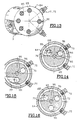
- the spray head may appear, as shown in Figure 1, under the shape of an annular sleeve 1 carried by a base or foot 2. This head has on its downstream face 3, several orifices represented by crosses. The water which arrives under pressure at the level of these orifices, is sprayed axially.
- This spray head 1 is arranged to receive at the level of aforementioned orifices, several families of spray nozzles such as example family number 1 which includes the nozzles marked 1.1, 1.2, 1.3 ... etc, up to 1.6, as well as a family number 2 marked 2.1, 2.2, for example and a family number 3 identified 3.1, 3.2.
- family number 1 which includes the nozzles marked 1.1, 1.2, 1.3 ... etc, up to 1.6
- family number 2 marked 2.1, 2.2 for example and a family number 3 identified 3.1, 3.2.
- Each family 1, 2, 3 is supplied with pressurized water in a way distinct, according to characteristics specific to each of them.
- the head 1 and in particular its body includes several chambers as shown in Figures 2 to 5, each of chambers used to supply a family or series of spray nozzles.
- Figures 2 to 5 show, schematically and simply functional, a section of the body of the spray head.
- This body of annular shape, figure 1, can just as well be rectilinear or other like for example in the form of a tuning fork; it has several bedrooms and particular three chambers in the detailed examples figures 2 to 5.
- an upstream chamber 5 constituting the main chamber, a chamber central 6 and a downstream chamber 7
- These rooms are arranged side by side, separated by partitions 56 for adjacent rooms 5 and 6, and 67 for rooms 6 and 7.
- This drilling makes it possible to house a spray nozzle 11 which is presented in the form of a cartridge 12 closed at its upstream end and provided with a nozzle 13 at its downstream end.
- the seal between the cartridge 12 and the various walls of the chambers and of the body of the head 1 is produced by means of seals 14.
- the cartridge 12 is immobilized by any appropriate means on the body 1.
- the spray nozzle 11 shown in FIG. 2 is a nozzle which corresponds to family number 1. This nozzle is in communication with the chamber 5 which receives pressurized water, as shown in FIG. 5, at by means of a supply line 15.
- rooms 6 and 7 are supplied in a separated and respectively by conduits 16 and 17.
- Each room 5, 6 or 7 can therefore be used to power the different families of nozzles.
- the chamber 5 supplies the nozzles of the family number 1.
- the cartridge 12 has in fact one or more orifices 21 which allow to connect the chamber 5 with the nozzle, the water being ejected through the nozzle 13.
- Figures 3 and 4 represent, like Figure 2, a section of chambers 5, 6 and 7 as well as nozzles 11.
- FIG. 3 shows a nozzle 11, the cartridge 12 of which includes orifices 22 which allow said nozzle to be in communication with the chamber 6 for spraying pressurized water through the nozzle 13.
- Figure 4 shows the nozzle 11 and in particular its cartridge 12 provided orifices 23 which put said nozzle in communication with the chamber 7.
- FIG. 1 illustrates, for a first embodiment, a head spray which comprises an annular sleeve-shaped body provided with a foot 2.
- the body and foot 2 are preferably made by molding so monobloc, in light alloy.
- Chambers 5, 6 and 7 which are annular in shape, can be obtained directly by molding.
- the foot 2 has the channels corresponding to the pipes 15, 16 and 17 shown in Figure 5. This leg 2 is also arranged to be able to be fixed for example on a pole 25 like that described in the document FR-2,743,872.
- This pole 25 which appears in thin broken lines in Figure 6, includes tubes obtained for example directly by spinning, which allow supplying pressurized water to the chambers of the spraying device and, in addition, thanks to a central pipe, to supply air under pressure, a nucleation device or nucleator.
- This nucleation device comprises a support 29 in the form of a bar vertical centered in the median vertical plane of the spray head and fixed to the upstream inlet of said head.
- This support 29 comprises a channel 30 which is used for passage of pressurized air and a channel 31 which serves for the passage of water under pressure, which channel 31 is supplied by means of a bypass 32 or tapping on the supply channel 15 of the chamber 5 which constitutes the master bedroom.
- the channel 31 also extends to the upper part of the support 29 and it allows the supply of a particular nozzle 11 'which passes through the chambers 5, 6, 7, and the upper part of the support 29.
- This nozzle 11 ' is present under the form of a cartridge also tightly mounted in the body 1 and this nozzle 11 ′ is provided, at the level of the channel 31, with orifices 33 which allow the passage of water under pressure to the spray nozzle 13.
- a circulation of water is thus obtained in the support 29 and as detailed below, in the nucleator 27 proper, which has the effect avoid freezing or even defrost the water and / or air jet of said nucleator, when from the commissioning of the installation or during its operation.
- the channel 30 arranged in the support 29 is in communication with the channel 18 which conveys the air under pressure.
- Figure 9 shows in more detail, the nucleator 27 well said.
- This nucleator comprises in the example shown, a nozzle central 35 which sprays the air brought under pressure through the channel 30, and a nozzle 36 to spray the water which is brought under pressure through the channel 31.
- the pressurized air arrives in a room 37 fitted in the support 29 and centered on the axis 9 of the spray head.
- This chamber 37 is closed by a cap 39 fixed at the rear, that is to say in upstream of the support 29 and this cap supports a filter 40 which is interposed between the channel 30 and the nozzle 35.
- the nozzle 35 is mounted on a drilled block 41 which is fixed on the downstream face of the support 29.
- This block 41 includes an axial cavity centered on the axis 9 for house the nozzle 35 and there is a chamber 42 arranged around the nozzle 35, substantially at mid-length, which chamber 42 communicates with channels 43 which allow a junction of the channels 31 arranged in the part lower and in the upper part of the support 29.
- These channels 43 establish a continuous circulation of water in the drilled block 41, around the nozzle 36 and around the nozzle 35.
- the nozzle 35 is a nozzle of the type provided with a deflector 45 which allows to get a flat spray.
- This flat air jet is struck by the water jet from the nozzle 36.
- This nozzle 36 is in fact placed under the nozzle 35, making an angle of the order 45 ° with axis 9 of nozzle 35.
- By striking the air jet the water jet turns into particles of ice or snow that will seed the jets of different nozzles 11 and 11 'in service.
- the orifice 38 of the nozzle 36 has a very small diameter, less than 1 mm. This nozzle 36 soaks in the circulating water to feed the nozzle 11 ', which avoids freezing and plugging of the orifice 38.
- this orifice 38 by its very small size, makes it possible to obtain a jet regular whatever the pressure in the supply circuit of the nozzle 11 '.
- the above nucleation device is of the external mixing type that is, water and air are mixed outside the head of spraying but in the central cavity 39 of the body and upstream of the nozzles 11.
- the air-water mixture is carried out with a very large ratio at least equal to 200.
- FIG. 7 shows the different nozzles 11 distributed over the downstream face 3 of the head body as well as the nozzle 11 'arranged at the upper part in the vertical median plane.
- the jets of these different nozzles are for example flat spectrum sprinklers arranged in parallel planes of each other way to form strata.
- Figure 8 shows, seen from the rear, the spray head fitted with the nucleation device 27.
- the nozzle 11 ' is also fixed by means of a screw 51 which appears Figures 6 and 8.
- FIG. 10 represents an alternative embodiment in which the nucleator is directly integrated into the body of the spray head. This nucleator actually comes in the form of a particular cartridge in form of mini high pressure snow cannon, located at the top of the head body 1.
- the body also has chambers 5, 6 and 7 which are supplied in pressurized water, a chamber 4 arranged upstream of the chambers previous, also annular in shape, and which is supplied with air under pressure by means of channel 18 which is arranged in foot 2 and communicates with said chamber 4.
- a particularly compact spraying device is thus obtained and homogeneous on which there is a nucleator consisting of a mini gun 52 and conventional spray nozzles 11 distributed over the downstream face 3 of the body of the head according to several families, each of these families being supplied by means of chambers 5, 6 or 7 as required with good sure all possibilities to realize a kind of mixing of nozzles.
- the nozzle or mini cannon 52 comprises a cartridge 53 which passes through tightly chambers 5, 6 and 7.
- This cartridge 53 is provided with an axial cavity which acts as a mixing chamber 54 and its wall is pierced with at least one orifice 55 located in chamber 5, which chamber is supplied with pressurized water. The cartridge 53 thus soaks in the supply water of the nozzles 11 which prevents freezing of the opening (s) 55.
- the orifice (s) 55 have a cross section which corresponds or which is even less than the circular section of an orifice whose diameter would be 1 mm. The pressure drop caused by this or these orifices allows operation of the nucleator regardless of the water pressure in the bedroom 5 in particular.
- the upstream wall of the mixing chamber 54 has orifices 56 to allow the passage of pressurized air from chamber 4.
- the water-air mixture takes place in chamber 54 and exits through the nozzle or nozzle 57. It is a mixture with a high air / water ratio, at least equal to 200.
- the upstream end of the cartridge 53 is in the form of a central rod 59 at the level of the channel 60 which connects the chamber 8 with chamber 54 of the mini cannon.
- the spray head shown in Figure 1 and Figure 11 is more particularly intended to be installed also at the end of a pole as in the case of the installation described in patent FR-2,743,872 of the Applicant.
- a part 63 can serve as an intermediary, as shown in the figure 11.
- This piece 63 is slightly bent to give head 1 a favorable inclination, close to vertical, or slightly inclined to cause the water to spray at an angle that promotes projection over the greatest possible distance depending on needs and site.
- the head 1, FIG. 11, consists of a tubular jacket 64 and a cylindrical core 65 centered in said jacket, the diameter of which is lower than that of said jacket to allow the passage of water under pressure.
- the core 65 has circular radial partitions which divide the internal space between the jacket 64 and said core, in several chambers.
- Partition 73 is located at the lower part of the core 65 and the partition 67 at the upper part.
- Each chamber supplies one or more sprinklers 75 located on a or several generatrices of the cylindrical envelope of the jacket 64.
- Room 66 which is the main room, can have several nozzles 75 distributed over several generators.
- the sprinklers 75 in rooms 70 and 72 are sprinklers which are implemented independently of those of the room 66, depending on climatic conditions to increase according to these climatic conditions the quantities of snow produced.
- Each room is fed by a channel which leads to its part lower.
- FIG. 11 the orifice 76 which opens into the chamber 66 at its lower part, that is to say at the level of the partition 69 of the core 65.
- a orifice 77 opens at the bottom of the chamber 70 at the level of the partition 71, and an orifice 79 opens into chamber 72 at the level of the partition 73.
- the seal between the jacket 64 and the various partitions 67, 69, 71 and 73, is produced by means of O-ring seals 80 arranged in the thickness of said partitions.
- the lower part of the core 65 has a base 81 in the form radial shoulder, on which the lower end 82 of the jacket 64.
- the core 65 extends above the upper end 83 of the shirt 64 and it is covered by a cap 84 which is fixed by screws 85 taken in the upper cylindrical end 86 of the core 65.
- the joint plane 87 between the shirt 64 and the cap 84 is disposed between the O-ring 80 of the partition 67 and an O-ring 89 arranged in a groove arranged in the upper cylindrical end 86 of the core 65.
- the cap 84 is positioned relative to the core 65 in a way specifies either by means of an original distribution of the screws 85 and / or a pin centering 90.
- This position of the cap 84 makes it possible to place the shirt 64 in a precise position also by means of the centering pin 90 interposed between both at the joint plane 87.
- the cap 84 includes at least one nucleation device 91 which makes acts as nucleator, to make particles of ice or snow which will then seed the different jets coming from the nozzles 75 of the spray head.
- This nucleation device 91 comprises a body cylindrical in the shape of a cartridge 92 inserted radially into an orifice fitted for this purpose in the cap 84, and a nozzle or nozzle 93 which is preferably oriented towards the jets of the different nozzles or nozzles 75 so to carry out the seeding.
- the cartridge 92 of the nucleation device is fixed by any means suitable in cap 84, for example by screwing; it will be detailed further.
- the nucleation device 91 which in fact constitutes a sort of mini high pressure snow cannon with very high air / water ratio, at least equal to 200, is supplied with pressurized water by one of the channels supply of the rooms and in particular by means of the channel which feeds master bedroom 66.
- This mini cannon is also supplied with pressurized air.
- a channel 95 disposed in the center of the core 65, which extends into the cap 84, in the form of a blind hole central. This channel 95 allows the pressurized air to be brought up to the level of the nucleation device 91 and in particular at the downstream inlet of the mixing of said device, detailed below.
- Chamber 66 is arranged just below the nucleation device 91; it is supplied with pressurized water by means of a channel 96 which also extends into the cap 84, which cap has a annular cavity 97 which is crossed by the cartridge 92 of the nucleation 91.
- the channel 96 extends over the entire length of the nucleus 65; he communicates with the annular cavity 97 fitted in the cap 84 and a second channel 99 arranged in the core 65 extends from said cavity 97 of the cap 84, to the lower part of chamber 66, opening at level of the orifice 76 in said chamber to supply the latter.
- the chamber 66 supplies several jets 75, arranged in pairs on two different generators. These sprinklers 75 are aligned vertically with the nozzles arranged at the level of the others chambers 70 and 72 and also with the nucleation devices 91.
- port 76 is located at the bottom of chamber 66.
- a small channel 100 of small diameter which extends between channel 99 and channel 96, arranged in such a way that it allows total drainage of the water located in the chamber 66, when the water supply is cut off.
- the diameter of this channel 100 is of the order of 1 / 5th of the diameter of the channels 96 and 99 in order to maintain a preferential circulation of water under pressure, in the cavity 97 of the cap 84.
- Figure 15 shows a section at the orifice 77 which allows the supply of the chamber 70 and of the nozzles 75.
- This orifice 77 is supplied by means of a channel 101 which extends axially in the core 65.
- FIG. 16 corresponds to a section at the level of the orifice 79 which serves to supply the chamber 72 and the lower nozzles 75.
- This chamber 72 is supplied by means of a channel 102 which extends parallel to the channel 101, at the channel 96 and to the central channel 95 which is used for the passage of compressed air.
- channel 102 is located under channel 99, centered practically on the same axis.
- the lower end of channel 99 and the end channel 102 are separated by a distance which corresponds substantially at the height of the chamber 70.
- Figure 12 shows the detail of one of the water introduction holes under pressure in the cartridge 92 of the nucleation device 91.
- This cartridge 92 of tubular shape, has in its central part an axial chamber 103 which opens downstream from the side of the nozzle 93 and which is open upstream on channel 95 in cap 84.
- the diameter of the axial mixing chamber 103 is substantially greater than the diameter of the outlet nozzle 93.
- the pressurized water used to supply the main chamber 66 is introduced radially into the mixing chamber 103 by means of orifices 94, preferably three orifices distributed over the periphery of the cartridge 92, the jets of which can be concurrent on the axis of said mixing chamber.
- the outer wall of the cartridge 92 is drilled radially with a first hole 104 whose diameter is less than 1 mm, and a second hole or counterbore 105 of much larger diameter.
- the diameter of hole 105 is of the order of ten times the diameter of hole 104.
- the length of hole 104 is of the same order as its diameter. So the water under pressure is injected into the mixing chamber 103 while crossing a sort of diaphragm which allows the 91 nucleation device to operate regardless of the pressure of the water introduced into the chamber main 66 for feeding sprinklers 75.
- the nucleation device can present the following characteristics: for an output at the nozzle 93 of the order 5.2 mm, we will adopt a diameter for the mixing chamber 103 of of the order of 7 mm and each of the three orifices 104 will have a diameter of the order of 0.6 mm.
- this nucleation device 91 is similar to a mini snow gun of the high pressure type, in which the air / water ratio is very important, at least equal to 200 and preferably much higher.
- the spray head 1 and in particular the base 106 of the core 65 is fixed by means of screws 107 to the intermediate connection 63, which connection 63 is itself fixed by means of screws, not shown, on the end of the mast 25.
- Figure 13 shows the distribution of the screws 85 which allow to fix the cap 84 on the upper end of the core 65.
- the distribution of the screws is such, as previously mentioned, that it imposes a precise orientation of the head relative to the core 65 and consequently an orientation also defined for the jacket 64 which carries the nozzles 75, by means of the centering pin 90 interposed between said jacket and said core.
- Figure 17 shows a variant of the spray head shown in Figure 11.
- This figure 17 shows a portion of the intermediate piece 63 on which is fixed the core 65 '.
- the core 65 ' is in the form of a molded and machined part, made of light alloy, and looks like a sort of drawer hydraulic threaded in an envelope 64 '.
- This 64 'envelope is itself consisting of a machined molded part, made of light alloy, held between the lower shoulder 81 of the core and the cap 84 'which is fixed by screws 85' to the upper end 86 'of the core 85'.
- Rooms 66, 70 and 72 are, as before, arranged between partitions. Thus we find the upper partition 67 which delimits with the partition 69, the annular chamber 66.
- the annular chamber 70 is delimited by the partition 69 and the partition 71.
- This partition 71 is interposed between the chamber 70 and the chamber 72, which annular chamber 72 is delimited at its lower part by the partition or shoulder 73.
- the partitions may have diameters which slightly increasing from the end of the core to its base 81.
- the chamber 70 is supplied by the orifice 77 and the chamber 72 is supplied by port 79.
- This nucleation device is presented as previously in FIG. 11, in the form of a cartridge 92.
- This cartridge 92 passes through the wall of the envelope 64 ′ in a sealed manner, and it is for example screwed onto this wall; it fits into a hole 110 arranged radially in the core 65 ', which orifice opens into the channel 95 for supplying pressurized air.
- the nucleation device is supplied with pressurized air at the upstream end of its mixing chamber 103, and the water supply under pressure, is effected by means of one or more orifices 94 arranged in the wall of the cartridge 92.
- These orifices 94 are located in the chamber 66, supplied with water under pressure at the same time as the spray nozzles 75.
- the cartridge 92 of the nucleation device 91 soaks in water which circulates in chamber 66 which avoids the phenomena of freezing and plugging the water injection holes in the mixing chamber 103.
- two devices can be positioned nucleation 91, making an angle close to 90 ° between them.
- These devices nucleation are arranged at the bottom of the main chamber 66, each under a vertical row of spray nozzles 75, which nozzles are represented three in number Figure 17, on the same line and in the same vertical plane.
- nucleation devices 91 are used to angularly position the casing 64 ′ of the spray head relative to to the core 65 'due to their fitting in radial cavities of this latest.
- the nozzle 93 of the nucleation device 91 is oriented like all the sprinklers 75, perpendicular to the longitudinal axis 109 of the head 1. It is arranged under the nozzles 75 of the main chamber 66 and not above as in the case of the head shown in Figure 11.
- Figures 17 and 18 show that the core 65 'has a countersink 111 at each of the holes 110 in which the cartridge is fitted 92 nucleation devices 91.
- the orifices 94 of the nucleation devices shown in FIG. 17, correspond to the orifices 94 represented in FIG. 12 in conjunction with FIG. 11.
- Figure 19 shows an alternative embodiment of the device assembly nucleation on the spray heads in the form of represented columns Figures 11 and 17.
- the nucleation device 91 ′ comprises a cartridge 92 ′ which is provided two nozzles or nozzles 93 '.
- the cartridge is centered in the median plane dihedral formed by the two rows of spray nozzles 75 while the nozzles 93 'are oriented parallel and respectively to each face said dihedral.
- This particular arrangement allows for seeding with a single nucleator, which nucleator has, in this case, orifices 94 in the cartridge 92 ′, for the injection of water, which are substantially superior to those of previous assemblies. We reduce even more, from this way the risk of freezing of the orifice (s) 104 in particular.
Landscapes
- Engineering & Computer Science (AREA)
- Physics & Mathematics (AREA)
- Mechanical Engineering (AREA)
- Thermal Sciences (AREA)
- General Engineering & Computer Science (AREA)
- Nozzles (AREA)
- Buildings Adapted To Withstand Abnormal External Influences (AREA)
- Road Signs Or Road Markings (AREA)
- Special Spraying Apparatus (AREA)
Applications Claiming Priority (5)
| Application Number | Priority Date | Filing Date | Title |
|---|---|---|---|
| FR9801581A FR2774610B1 (fr) | 1998-02-06 | 1998-02-06 | Dispositif de pulverisation d'eau sous pression |
| FR9801581 | 1998-02-06 | ||
| FR9813477A FR2784905B1 (fr) | 1998-10-23 | 1998-10-23 | Tete de pulverisation polyvalente utilisable notamment pour la fabrication de neige artificielle |
| FR9813477 | 1998-10-23 | ||
| PCT/FR1999/000258 WO1999040381A1 (fr) | 1998-02-06 | 1999-02-05 | Generateur de particules de glace, de neige, ou nucleateur, integre dans une tete de pulverisation d'eau |
Publications (2)
| Publication Number | Publication Date |
|---|---|
| EP1053440A1 EP1053440A1 (fr) | 2000-11-22 |
| EP1053440B1 true EP1053440B1 (fr) | 2004-01-14 |
Family
ID=26234124
Family Applications (1)
| Application Number | Title | Priority Date | Filing Date |
|---|---|---|---|
| EP99902606A Expired - Lifetime EP1053440B1 (fr) | 1998-02-06 | 1999-02-05 | Generateur de particules de glace, de neige, ou nucleateur, integre dans une tete de pulverisation d'eau |
Country Status (9)
| Country | Link |
|---|---|
| US (1) | US6508412B1 (ja) |
| EP (1) | EP1053440B1 (ja) |
| JP (1) | JP2002502951A (ja) |
| AT (1) | ATE257935T1 (ja) |
| AU (1) | AU2284199A (ja) |
| CA (1) | CA2319692A1 (ja) |
| DE (1) | DE69914182D1 (ja) |
| NO (1) | NO312380B1 (ja) |
| WO (1) | WO1999040381A1 (ja) |
Families Citing this family (23)
| Publication number | Priority date | Publication date | Assignee | Title |
|---|---|---|---|---|
| EP1456588B1 (de) | 2001-12-11 | 2006-03-01 | NIVIS GmbH - Srl | Beschneiungsvorrichtung und verfahren zum betrieb einer beschneiungsvorrichtung |
| US20040004134A1 (en) * | 2002-07-05 | 2004-01-08 | Santry Charles N. | Snow making apparatus |
| US20040050949A1 (en) * | 2002-08-14 | 2004-03-18 | Duper Herman K. | Snow making apparatus |
| DE102004053984B3 (de) * | 2004-10-08 | 2006-06-14 | Technoalpin Gmbh | Lanzenkopf für eine Schneelanze sowie Düsenanordnung |
| CA2593554C (en) * | 2005-01-13 | 2013-11-12 | Charles N. Santry | Freeze-proof water valve for supplying secondary water to a snow making apparatus |
| WO2008114286A1 (en) * | 2007-03-16 | 2008-09-25 | Weisser Wolf S.R.L. | Spray head for the production of artificial snow |
| WO2009018319A1 (en) * | 2007-07-31 | 2009-02-05 | Johnson Controls Technology Company | Snowmaking apparatus |
| US20090114735A1 (en) * | 2007-11-05 | 2009-05-07 | Johnson Controls Technology Company | Snowmaking methods |
| EP2217764A1 (en) * | 2007-11-07 | 2010-08-18 | Georg Fischer LLC | High purity water system |
| EP2071258A1 (de) | 2007-12-14 | 2009-06-17 | Bächler Top Track AG | Nukleatordüse, Verwendung einer Nukleatordüse, Schneekanone, Schneilanze und Verfahren zum Erzeugen von Eiskeimen und von künstlichem Schnee |
| CN102164681B (zh) | 2008-09-25 | 2016-09-07 | 斯诺泰克独家制造的销售的有限公司 | 包含固定或可变喷射角度的具有可调液滴尺寸的平面射流流体喷嘴 |
| US8376245B2 (en) * | 2010-01-18 | 2013-02-19 | Ratnik Industries, Inc. | Snow making apparatus and method |
| WO2014036344A2 (en) | 2012-08-29 | 2014-03-06 | Snow Logic, Inc. | Single and multi-step snowmaking guns |
| US9395113B2 (en) | 2013-03-15 | 2016-07-19 | Mitchell Joe Dodson | Nucleator for generating ice crystals for seeding water droplets in snow-making systems |
| UA108714C2 (uk) * | 2011-10-01 | 2015-05-25 | Спосіб одержання снігу та пристрій для здійснення способу | |
| AU2013308668A1 (en) | 2012-08-29 | 2015-04-16 | Mitchell Joe Dodson | Modular dual vector fluid spray nozzles |
| US20160290699A1 (en) * | 2015-04-06 | 2016-10-06 | Snow Logic, Inc. | Snowmaking automation system and modules |
| ES1151309Y (es) * | 2016-01-12 | 2016-05-17 | Mecanitzats Ramon Nuri S L | Cabezal y mástil para máquina para fabricar nieve |
| US11052411B2 (en) | 2017-10-11 | 2021-07-06 | Richard Marcelin Wambsgans | Device and method to create nano-particle fluid nucleation sites in situ |
| US10234186B1 (en) | 2017-11-09 | 2019-03-19 | James Chun Koh | Apparatus for manufacturing powdered ice with salinity |
| US20200033041A1 (en) | 2018-07-25 | 2020-01-30 | James Chun Koh | Apparatus for making fine ice with salinity |
| FR3103030B1 (fr) | 2019-11-07 | 2022-06-17 | Technoalpin France | Dispositif de pulvérisation pour la fabrication de neige artificielle et son procédé de mise en œuvre |
| FR3116449B1 (fr) | 2020-11-20 | 2022-12-09 | Ingenierie De Loisirs | Tête de pulvérisation pour produire de la neige |
Family Cites Families (11)
| Publication number | Priority date | Publication date | Assignee | Title |
|---|---|---|---|---|
| US3829013A (en) | 1971-11-03 | 1974-08-13 | H Ratnik | Snow making apparatus |
| US3979061A (en) * | 1974-02-04 | 1976-09-07 | Kircher Everett F | Method and apparatus for making artificial snow |
| US3964682A (en) * | 1975-03-17 | 1976-06-22 | Tropeano Philip L | Method and apparatus for making snow produced by cumulative crystallization of snow particles |
| DE3368757D1 (en) * | 1982-03-22 | 1987-02-05 | Stig L Albertsson | Snow making machine |
| US4593854A (en) * | 1984-04-25 | 1986-06-10 | Albertsson Stig L | Snow-making machine |
| US4742959A (en) * | 1986-11-20 | 1988-05-10 | Killington Ltd. | Snow gun |
| US4916911A (en) * | 1987-05-21 | 1990-04-17 | Dendrite Associates, Inc. | Snowmaking process and apparatus |
| JPH0730984B2 (ja) * | 1988-09-30 | 1995-04-10 | 日本鋼管株式会社 | 室内スキー場における造雪方法 |
| US5699961A (en) * | 1995-05-05 | 1997-12-23 | Ratnik Industries, Inc. | Fanless snow gun |
| CA2258424C (en) * | 1995-10-30 | 2000-04-25 | Vernon Lorne Mckinney | Snow gun for making artificial snow |
| FR2743872B1 (fr) | 1996-01-22 | 1998-04-10 | York Neige | Support de buse de pulverisation |
-
1999
- 1999-02-05 CA CA002319692A patent/CA2319692A1/fr not_active Abandoned
- 1999-02-05 AT AT99902606T patent/ATE257935T1/de active
- 1999-02-05 EP EP99902606A patent/EP1053440B1/fr not_active Expired - Lifetime
- 1999-02-05 AU AU22841/99A patent/AU2284199A/en not_active Abandoned
- 1999-02-05 JP JP2000530751A patent/JP2002502951A/ja not_active Withdrawn
- 1999-02-05 DE DE69914182T patent/DE69914182D1/de not_active Expired - Lifetime
- 1999-02-05 US US09/601,680 patent/US6508412B1/en not_active Expired - Lifetime
- 1999-02-05 WO PCT/FR1999/000258 patent/WO1999040381A1/fr active IP Right Grant
-
2000
- 2000-08-04 NO NO20003957A patent/NO312380B1/no not_active IP Right Cessation
Also Published As
| Publication number | Publication date |
|---|---|
| EP1053440A1 (fr) | 2000-11-22 |
| NO312380B1 (no) | 2002-04-29 |
| JP2002502951A (ja) | 2002-01-29 |
| WO1999040381A1 (fr) | 1999-08-12 |
| US6508412B1 (en) | 2003-01-21 |
| NO20003957L (no) | 2000-10-05 |
| CA2319692A1 (fr) | 1999-08-12 |
| AU2284199A (en) | 1999-08-23 |
| ATE257935T1 (de) | 2004-01-15 |
| DE69914182D1 (de) | 2004-02-19 |
| NO20003957D0 (no) | 2000-08-04 |
Similar Documents
| Publication | Publication Date | Title |
|---|---|---|
| EP1053440B1 (fr) | Generateur de particules de glace, de neige, ou nucleateur, integre dans une tete de pulverisation d'eau | |
| FR2784905A1 (fr) | Tete de pulverisation polyvalente utilisable notamment pour la fabrication de neige artificielle | |
| EP2026002A1 (fr) | Injecteur multipoint pour turbomachine | |
| EP0018280A2 (fr) | Canon à neige haute pression et batterie de tels canons à neige | |
| FR2481148A1 (fr) | Buse de pulverisation par atomisation | |
| FR2500331A1 (fr) | Buse de pulverisation binaire | |
| WO2007006987A1 (fr) | Extincteur a brouillard de liquide et son utilisation | |
| EP1123479B1 (fr) | Tete de pulverisation polyvalente pour la fabrication de neige artificielle | |
| FR2594528A1 (fr) | Embout de melange de fluides pour appareil de fabrication de neige artificielle | |
| EP1386668A1 (fr) | Dispositif de pulvérisation d'eau sous forme d'un jet creux a paroi mince, pour la formation de neige artificielle | |
| EP0683886B1 (fr) | Canon a neige | |
| EP1196725B1 (fr) | Dispositif d'alimentation d'un canon a neige | |
| FR2943119A1 (fr) | Systemes d'injection de carburant dans une chambre de combustion de turbomachine | |
| FR2774610A1 (fr) | Dispositif de pulverisation d'eau sous pression | |
| FR2621018A1 (fr) | Distributeur de fluide dans un reservoir sous pression empechant une stratification thermique | |
| FR2498301A1 (fr) | Procede, appareil et injecteur pour bruler une matiere contenant des hydrocarbures avec reduction des fumees | |
| EP1114287B1 (fr) | Canon a neige | |
| EP0690971A1 (fr) | Buse de pulverisation et dispositif de pulverisation d'un melange d'eau et d'air utilisant ladite buse | |
| CA2343429C (fr) | Installation de depoussierage de gaz par manches filtrantes, comportant un dispositif pneumatique de decolmatage periodique | |
| BE389521A (ja) | ||
| FR2602698A1 (fr) | Generateur d'aerosol et installation pour l'etude de l'ecoulement d'un courant de gaz | |
| FR2510008A1 (fr) | Atomiseur, notamment pour refroidir dans le sens de sa largeur un produit coule en continu | |
| BE636040A (ja) | ||
| CN109168756A (zh) | 一种装配式建筑绿化装置 | |
| FR2721172A1 (fr) | Régulateur de pression pour dispositif mobile d'éjection à usage agricole. |
Legal Events
| Date | Code | Title | Description |
|---|---|---|---|
| PUAI | Public reference made under article 153(3) epc to a published international application that has entered the european phase |
Free format text: ORIGINAL CODE: 0009012 |
|
| 17P | Request for examination filed |
Effective date: 20000906 |
|
| AK | Designated contracting states |
Kind code of ref document: A1 Designated state(s): AT CH DE ES FR IT LI SE |
|
| 17Q | First examination report despatched |
Effective date: 20020717 |
|
| GRAH | Despatch of communication of intention to grant a patent |
Free format text: ORIGINAL CODE: EPIDOS IGRA |
|
| GRAS | Grant fee paid |
Free format text: ORIGINAL CODE: EPIDOSNIGR3 |
|
| GRAA | (expected) grant |
Free format text: ORIGINAL CODE: 0009210 |
|
| AK | Designated contracting states |
Kind code of ref document: B1 Designated state(s): AT CH DE ES FR IT LI SE |
|
| REG | Reference to a national code |
Ref country code: CH Ref legal event code: EP |
|
| REF | Corresponds to: |
Ref document number: 69914182 Country of ref document: DE Date of ref document: 20040219 Kind code of ref document: P |
|
| PG25 | Lapsed in a contracting state [announced via postgrant information from national office to epo] |
Ref country code: LI Free format text: LAPSE BECAUSE OF NON-PAYMENT OF DUE FEES Effective date: 20040229 Ref country code: CH Free format text: LAPSE BECAUSE OF NON-PAYMENT OF DUE FEES Effective date: 20040229 |
|
| PG25 | Lapsed in a contracting state [announced via postgrant information from national office to epo] |
Ref country code: SE Free format text: LAPSE BECAUSE OF FAILURE TO SUBMIT A TRANSLATION OF THE DESCRIPTION OR TO PAY THE FEE WITHIN THE PRESCRIBED TIME-LIMIT Effective date: 20040414 |
|
| PG25 | Lapsed in a contracting state [announced via postgrant information from national office to epo] |
Ref country code: DE Free format text: LAPSE BECAUSE OF FAILURE TO SUBMIT A TRANSLATION OF THE DESCRIPTION OR TO PAY THE FEE WITHIN THE PRESCRIBED TIME-LIMIT Effective date: 20040415 |
|
| PG25 | Lapsed in a contracting state [announced via postgrant information from national office to epo] |
Ref country code: ES Free format text: LAPSE BECAUSE OF FAILURE TO SUBMIT A TRANSLATION OF THE DESCRIPTION OR TO PAY THE FEE WITHIN THE PRESCRIBED TIME-LIMIT Effective date: 20040425 |
|
| REG | Reference to a national code |
Ref country code: CH Ref legal event code: PL |
|
| PLBQ | Unpublished change to opponent data |
Free format text: ORIGINAL CODE: EPIDOS OPPO |
|
| PLBI | Opposition filed |
Free format text: ORIGINAL CODE: 0009260 |
|
| PLAX | Notice of opposition and request to file observation + time limit sent |
Free format text: ORIGINAL CODE: EPIDOSNOBS2 |
|
| 26 | Opposition filed |
Opponent name: SUFAG SPORT- UND FREIZEITANLAGEN GMBHPATENTANWALT Effective date: 20041011 |
|
| PLBB | Reply of patent proprietor to notice(s) of opposition received |
Free format text: ORIGINAL CODE: EPIDOSNOBS3 |
|
| PLAB | Opposition data, opponent's data or that of the opponent's representative modified |
Free format text: ORIGINAL CODE: 0009299OPPO |
|
| R26 | Opposition filed (corrected) |
Opponent name: SUFAG SPORT- UND FREIZEITANLAGEN GMBH Effective date: 20041011 |
|
| PLCK | Communication despatched that opposition was rejected |
Free format text: ORIGINAL CODE: EPIDOSNREJ1 |
|
| APBM | Appeal reference recorded |
Free format text: ORIGINAL CODE: EPIDOSNREFNO |
|
| APBP | Date of receipt of notice of appeal recorded |
Free format text: ORIGINAL CODE: EPIDOSNNOA2O |
|
| APAH | Appeal reference modified |
Free format text: ORIGINAL CODE: EPIDOSCREFNO |
|
| APBU | Appeal procedure closed |
Free format text: ORIGINAL CODE: EPIDOSNNOA9O |
|
| PLBN | Opposition rejected |
Free format text: ORIGINAL CODE: 0009273 |
|
| STAA | Information on the status of an ep patent application or granted ep patent |
Free format text: STATUS: OPPOSITION REJECTED |
|
| 27O | Opposition rejected |
Effective date: 20110331 |
|
| REG | Reference to a national code |
Ref country code: FR Ref legal event code: PLFP Year of fee payment: 18 |
|
| REG | Reference to a national code |
Ref country code: FR Ref legal event code: PLFP Year of fee payment: 19 |
|
| REG | Reference to a national code |
Ref country code: FR Ref legal event code: PLFP Year of fee payment: 20 |
|
| PGFP | Annual fee paid to national office [announced via postgrant information from national office to epo] |
Ref country code: FR Payment date: 20171201 Year of fee payment: 20 |
|
| PGFP | Annual fee paid to national office [announced via postgrant information from national office to epo] |
Ref country code: IT Payment date: 20180209 Year of fee payment: 20 Ref country code: AT Payment date: 20171206 Year of fee payment: 20 |
|
| REG | Reference to a national code |
Ref country code: AT Ref legal event code: MK07 Ref document number: 257935 Country of ref document: AT Kind code of ref document: T Effective date: 20190205 |