EP1053412B1 - Short pitch tooth chain - Google Patents
Short pitch tooth chain Download PDFInfo
- Publication number
- EP1053412B1 EP1053412B1 EP99905913.2A EP99905913A EP1053412B1 EP 1053412 B1 EP1053412 B1 EP 1053412B1 EP 99905913 A EP99905913 A EP 99905913A EP 1053412 B1 EP1053412 B1 EP 1053412B1
- Authority
- EP
- European Patent Office
- Prior art keywords
- link
- chain
- links
- tension
- tooth chain
- Prior art date
- Legal status (The legal status is an assumption and is not a legal conclusion. Google has not performed a legal analysis and makes no representation as to the accuracy of the status listed.)
- Expired - Lifetime
Links
Images


Classifications
-
- F—MECHANICAL ENGINEERING; LIGHTING; HEATING; WEAPONS; BLASTING
- F16—ENGINEERING ELEMENTS AND UNITS; GENERAL MEASURES FOR PRODUCING AND MAINTAINING EFFECTIVE FUNCTIONING OF MACHINES OR INSTALLATIONS; THERMAL INSULATION IN GENERAL
- F16G—BELTS, CABLES, OR ROPES, PREDOMINANTLY USED FOR DRIVING PURPOSES; CHAINS; FITTINGS PREDOMINANTLY USED THEREFOR
- F16G13/00—Chains
- F16G13/02—Driving-chains
- F16G13/04—Toothed chains
Definitions
- the present invention relates to the chain arts, and in particular, a short pitch tooth chain that provides improved noise reduction over conventional tooth chains.
- Drive chain systems and timing chain systems incorporating known chains such as inverted tooth chains and roller chains have several components of undesirable noise.
- a major source of noise is the sound generated as the chain engaging members, such as inverted teeth or rollers, leave the span and collide with a sprocket during meshing. The resulting impact noise is repeated with a frequency generally equal to that of the frequency of the chain meshing with the sprocket. It is known that the impact noise levels associated with chains can be reduced by altering the engagement geometry of the chain and/or sprocket to, in part, reduce the impact energy that must be absorbed during the meshing process.
- the present invention contemplates a new and improved short pitch tooth chain which provides improved noise reduction over conventional inverted tooth chains.
- US-A1-2655816 discloses a silent chain structure including an automatic slack take-up assembly, comprising a plurality of chain links interconnected by pins of identical construction, each of said pins having operatively associated therewith double liners each defining a bushing with a curvature whose radii vary in length and are less than the diameter of their associated pin and arranged so that the pin is forced to nest in the bushing by deflecting the curvature of the bushing when load is placed upon the chain, said arrangement being particularly characterized in its operation by a spring action of each joint responsive to the load place upon the chain.
- EP-A-0877178 which falls under Article 54(3) EPC, discloses a chain assembly using formed bushings with inverted teeth in which a roller chain is provided with a bushing with a silent chain link profile.
- the bushing has a pair of depending toes which engage the teeth of a sprocket to provide power transmission.
- a tooth chain comprising a plurality of link members each comprising a body portion defining a first toe and a second toe spaced from the first toe by a predetermined distance (T p ), the toes adapted for meshing engagement with tooth spaces associated with a sprocket and wherein each of said link members further comprises a single aperture extending through the body portion, said tooth chain further comprising a plurality of tension links each comprising first and second apertures spaced from each other by a chain pitch distance (C p ), each of said tension links including a first one of said link members pivotally connected to said tension link by a first pin that extends through said first aperture of said tension link and through said single aperture of said first link member, and a second one of said link members pivotally connected to said tension link by a second pin that extends through said second aperture of said tension link and through said single aperture of said second link member, such that each tension link carries two of said link members.
- a chain system comprising a tooth chain according to the aforesaid first aspect of the invention said tooth chain meshed with first and second sprockets and the first and second sprockets each defining a sprocket chordal pitch (S p ) that is substantially equal to the predetermined distance (T p ).
- One advantage of the present invention is the provision of a short pitch tooth chain which reduces noise levels by increasing the frequency at which the chain meshes with a sprocket to a level which is inaudible, or at least less audible to the human ear.
- Another advantage of the present invention is the provision of a short pitch tooth chain having a chain pitch value which is approximately twice a sprocket chordal pitch value.
- a further advantage of the present invention is the provision of a chain system having a short pitch tooth chain that reduces noise levels by increasing the frequency at which the chain meshes with a sprocket to a level which is inaudible, or at least less audible to the human ear.
- Yet another advantage of the present invention is the provision of chain system having a short pitch tooth chain with a chain pitch value which is approximately twice a sprocket chordal pitch value.
- a conventional double-toed link 10 for a known inverted tooth chain 11 includes a body portion 12 having a first toe 14 spaced from a second toe 16.
- the toes 14, 16 consecutively engage adjacent and mutually conforming tooth spaces 17 associated with a sprocket 17a.
- the link 10 also includes a first aperture 18 and a second aperture 20 spaced apart from the first aperture.
- the apertures 18, 20 receive conventional pins 21 for joining together a number of different links, including links 10, to form the known inverted tooth chain 11.
- Such a conventional double-toed link is disclosed in US-A-2655816 .
- a major source of chain drive noise is the sound generated as the chain engaging members, i.e. the toes 14, 16, leave the span and collide with the sprocket during meshing.
- the resultant impact noise is repeated with a frequency generally equal to that of the frequency of the chain meshing with the sprocket. It is contemplated herein that the overall noise levels associated with a chain drive system can be reduced by increasing the frequency at which the chain meshes with the sprocket to a level which is inaudible, or at least less audible, to the human ear.
- reducing the chain pitch C p of the conventional link 10 to about 8.0mm or less is problematic.
- the size of the link 10 decreases, and a corresponding decrease in strength and load capacity of the chain results. More particularly, as the size of the link 10 decreases, there is less link material between the apertures 18, 20, and between each aperture 18, 20 and the corresponding edge of the link 10 thereby resulting in a structurally weaker link.
- a chain system 30 such as a drive chain system, timing chain system, etc. which incorporates the features of the present invention therein.
- the chain system 30 rotates in a counter-clockwise direction as shown by arrow 32.
- the chain system 30 includes at least a drive sprocket 34, a driven sprocket 36, and a short pitch tooth chain 38.
- the short pitch tooth chain 38 engages and wraps about sprockets 34 and 36 and has two spans extending between the sprockets, slack strand 40 and taut strand 42.
- the taut strand 42 is under tension as shown by arrows 44.
- the short pitch tooth chain 38 includes a number of double-toed links 46, tension links 48, and pins 50 interconnecting the links 46, 48.
- the links 46, 48 are each pivotal about the pins 50 so that as the links enter the sprocket wrap, each link may articulate independently about the respective pin to conform with the curvature of the sprocket.
- the links 46, 48 and pins 50 may be interconnected in various lacing patterns known in the art to produce short pitch tooth chains having different strength and load capacity characteristics.
- An exemplary lacing pattern is shown in Figure 4 .
- the dimensions (e.g. length, width, height, etc.) and material considerations (powdered metal, stamped metal, steel, etc.) of the links 46, 48 and the pins 50 can be varied to produce chains having different strength and load capacity characteristics in a known manner.
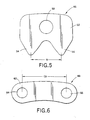
- the double-toed link 46 ( Figure 5 ) includes a body portion 52 having a first toe 54 spaced from a second toe 56 by a distance T p (toe pitch).
- a central aperture 58 extends through the body portion 52.
- the toes 54, 56 engage mutually conforming tooth spaces 59, 60 ( Figure 3 ) of the sprockets 34, 36, respectively.
- the sprockets 34, 36 each have sprocket chordal pitch S p which is substantially equal to the toe pitch T p . It should be appreciated that by providing a link 46 with a single aperture therethrough, more link material extends between the aperture and each side edge thereof, relative to the link 10.
- the tension link 48 ( Figure 6 ) primarily carries the load on the chain 38.
- Each tension link 48 includes an arcuate-shaped body portion 62 having a first aperture 64 proximate one end thereof, and a second aperture 66 proximate the other end.
- each tension link 48 carries two double-toed links 46 via two pins 50 each extending through a respective aperture 64, 66.
- the chain pitch C p for the chain 38 is defined as the distance between the centers of the apertures 64, 66.
- the tension links 48 have substantially the same chain pitch C p as the prior art links 10.
- the chain 38 maintains substantially the same high-strength and load capacity characteristics as a known inverted tooth chain incorporating the links 10.
- the chain 38 also permits the sprocket chordal pitch S p to be reduced to substantially one-half of the chain pitch.
- the overall noise levels associated with the chain 38 are reduced by increasing the frequency at which the chain meshes with the sprockets to a level which is inaudible, or at least less audible to the human ear.
- a timing, drive, etc. chain system 80 incorporates the features of the present invention therein.
- the chain system 80 rotates in a counter-clockwise direction as shown by arrow 82, and includes a drive sprocket 84, a driven sprocket 86, and a short pitch tooth chain 88.
- the short pitch tooth chain 88 engages and wraps about sprockets 84 and 86 and has two spans extending between the sprockets, slack strand 90 and taut strand 92.
- the taut strand 92 is under tension as shown by arrows 94.
- the short pitch tooth chain 88 includes a number of double-toed links 96, tension links 98, guide links 100, spring links 102, and pins 104.
- the double-toed links 96, tension links 98, and spring links 102 are each pivotal about the pins 104.
- the double-toed links 96, tension links 98, guide links 100, and spring links 102 may be interconnected in various lacing patterns to produce chains having different strength and load capacity characteristics.
- FIG. 8 An exemplary lacing pattern is shown in Figure 8 .
- the tension links 98 and guide links 100 can be interchanged.
- the dimensions (e.g. length, width, height, etc.) and material considerations of the various links and pins can be varied to produce chains having different strength and load capacity characteristics in a known manner.
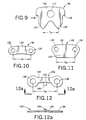
- the double-toed link 96 ( Figure 9 ) includes a body portion 106 having a first toe 108 spaced from a second toe 110 by a distance T p (toe pitch).
- a central aperture 112 extends through the body portion 106.
- the toes 108, 110 engage mutually conforming tooth spaces 114, 116 ( Figure 7 ) of the sprockets 84, 86, respectively.
- the sprockets 84, 86 each have a sprocket chordal pitch S p which is substantially equal to the toe pitch T p .
- the link 96 also includes a ledge or shoulder portion 118 on each side thereof.
- the tension links 98 ( Figure 10 ) primarily carry the load on the chain 88.
- Each tension link 98 includes a body portion 120 having a first aperture 122 proximate one end thereof and a second aperture 124 proximate the other end.
- each tension link 98 carries two double-toed links 96 via two pins 104 each extending through a respective aperture 122, 124.
- the guide links 100 ( Figure 11 ) primarily constrain lateral movement of the chain 88 relative to the sprockets 84, 86. In the embodiment being described, the guide links 100 are not pivotal relative to the pins 104. Each guide link 100 includes a body portion 126 having a first aperture 128 proximate one end thereof and a second aperture 130 proximate the other end. As with the tension links 98, the centers of the apertures 128, 130 are separated by the distance C p .
- the guide links 100 also include an extended lower portion 132 which is constrained within a groove (not shown) on an external peripheral surface of the sprockets 84, 86 when the link 100 enters the respective sprocket wraps.
- the guide links 100 can also carry the chain load.
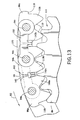
- each spring link 102 provides means for preventing adjacent double-toed links 96 from contacting each other in the slack strand 90 or taut strand 92.
- each spring link 102 includes a body portion 134 having a first aperture 136 proximate one end thereof and a second aperture 138 proximate the other end. As with the other links 98, 100, the centers of the apertures 136, 138 are separated by the distance C p .
- the spring links 102 also include a cantilevered arm portion 140 extending transversely from a central portion of the body 134. A blade spring 142 or other biasing means is secured to a free end of the arm 140.
- the blade springs 142 are interposed between adjacent double-toed links 96 such that the blade springs 142 are in tension by continuously contacting mutually opposing side walls of adjacent links 96.
- the double-toed links 96 are freely articulatable about the respective pins 94. Accordingly, the blade springs 142 urge the adjacent links 96 apart to prevent the links 96 from impacting, and thus generating undesirable noise.
- the tension links 98 and guide links 100 have substantially the same chain pitch C p as the prior art links 10.
- the chain 88 maintains substantially the same high-strength and load capacity characteristics as a known inverted tooth chain incorporating the links 10.
- the chain 88 also permits the sprocket chordal pitch S p to be reduced to substantially one-half of the chain pitch.
- the overall noise levels associated with the chain 88 are reduced by increasing the frequency at which the chain meshes with the sprockets to a level which is inaudible, or at least less audible to the human ear.
- a timing, drive, etc. chain system 150 incorporates the features of the present invention therein.
- the chain system 150 rotates in a counter-clockwise direction as shown by arrow 152, and includes a drive sprocket 154, a driven sprocket 156, and a short pitch tooth chain 158.
- the short pitch tooth chain 158 engages and wraps about sprockets 154 and 156 and has two spans extending between the sprockets, slack strand 160 and taut strand 162.
- the taut strand 162 is under tension as shown by arrows 164.
- the short pitch tooth chain 158 includes a number of double-toed links 166, tension links 168, guide links 170, and pins 172.
- the double-toed links 166 and tension links 168 are each pivotal about the pins 172.
- the guide links 170 are not pivotal relative to the pins 172.
- the double-toed links 166, tension links 168, and guide links 170 may be interconnected in various lacing patterns to produce chains having different strength and load capacity characteristics.
- An exemplary lacing pattern is shown in Figures 15 and 16 .
- the dimensions (e.g. length, width, height, etc.) and material considerations of the various links and pins can be varied to produce chains having different strength and load capacity characteristics in a known manner.
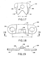
- the double-toed link 166 ( Figure 17 ) includes a body portion 176 having a first toe 178 spaced from a second toe 180 by a distance T p (toe pitch).
- a central aperture 182 extends through the body portion 176.
- the toes 178, 180 engage mutually conforming tooth spaces 184, 186 ( Figure 14 ) of the sprockets 154, 156, respectively.
- the sprockets 154, 156 each have a sprocket chordal pitch S p which is substantially equal to the toe pitch T p .
- the link 166 also includes a ledge or shoulder portion 188 on each side thereof.
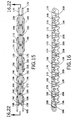
- the tension links 168 ( Figures 18 and 19 ) primarily carry the load on the chain 158.
- Each tension link 168 includes a body portion 190 having a first aperture 192 proximate one end thereof and a second aperture 194 proximate the other end.
- each tension link 168 carries two double-toed links 166 via two pins 172 each extending through a respective aperture 192, 194 and link 166.
- the tension link 168 further includes a raised pad 196 for supporting a wedge portion 198.
- the wedge portion 198 forms a trapezoid in a plan view.
- the pad portion 196 extends between two adjacent guide links 170, and the wedge portion 198 extends between two adjacent double-toed links 166.
- the thickness 196a of the raised pad 196 is substantially equal to the thickness of the guide links 170 to permit the wedge portion 198 to extend at least partially between adjacent double-toed links 166.
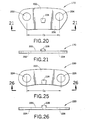
- the guide links 170 ( Figures 20 and 21 ) primarily constrain lateral movement of the chain 158 relative to the sprockets 154, 156.
- Each guide link 170 includes a body portion 200 having a first aperture 202 proximate one end thereof and a second aperture 204 proximate the other end. As with the tension links 168, the centers of the apertures 202, 204 are separated by the distance C p .
- the guide links 170 also include an extended lower portion 206 which is constrained within a groove (not shown) on an external peripheral surface of the sprockets 154, 156 when the link 170 enters the respective sprocket wraps.
- the guide links 170 can also carry a portion of the loading on the chain 158.
- the guide link 170 further includes a raised wedge portion 208.
- the wedge portion 208 forms a trapezoid in a plan view. As best seen in Figure 15 , the wedge portion 208 extends at least partially between two adjacent double-toed links 166.
- the wedge portions 198, 208 provide means for preventing adjacent double-toed links 96 from inadvertently contacting each other in the slack strand 160 or taut strand 162.
- the raised wedge portion 208b of guide link 170b extends between adjacent double-toed links 166c, 166d.
- the mutually opposing shoulder portions 188 of the links 166c, 166d abut the wedge portion 208b and thus prevent the adjacent double-toed links from articulating about the pins 172 while in the strands 160, 162.
- the wedge portion 198a of the tension link 168a extends between adjacent double-toed links 166b, 166c.
- the mutually opposing shoulder portions 188 of the links 166b, 166c abut the raised wedge portion 198a and thus prevent the double-toed links from articulating about the pins 172 while in the strands 160, 162.
- the trapezoidal shape of the raised wedge portions 198, 208 permit adjacent double-toed links 166 to pivot toward each other in the sprocket wrap.
- the side walls of the wedge portion 208a converge in a radially inward direction (relative to the sprocket center) to permit the toes 180a, 178b to consecutively pivot toward each other as the links enter the sprocket wrap.
- the links 166 will exit the wrap back into the slack strand 160.
- the links 166 will rotate about the respective pins 172 until the shoulder portions 188 abut the wedge portions 198, 208 to prevent the links 166 from impacting, and thus generating undesirable noise.
- the frequency of impacts between the toes 178, 180 and the tooth spaces 184, 186 is increased, while maintaining high strength and load capacity characteristics of the conventional chain 11. That is, the tension links 168 and guide links 170 have substantially the same chain pitch C p as the prior art links 10.
- the overall noise levels associated with the chain 158 are reduced by increasing the frequency at which the chain meshes with the sprockets to a level which is inaudible, or at least less audible to the human ear.
- the double-toed links 166, tension links 168, and guide links 170 may be interconnected in various lacing patterns to produce chains having different strength and load capacity characteristics.
- Figures 22 and 23 illustrate an exemplary lacing pattern having greater strength and load capacity characteristics than the lacing pattern of Figures 15 and 16 .
- two different tension link configurations must be utilized.
- a second tension link 220 includes a body portion 222 having a first aperture 224 proximate one end thereof and a second aperture 226 proximate the other end.
- each tension link 220 carries two double-toed links 166 via two pins 172 each extending through a respective aperture 224, 226.
- the second tension link 220 further includes a raised wedge portion 228 that forms a trapezoid in a plan view.
- the wedge portion 228 extends at least partially between two adjacent double-toed links 166 to prevent the double-toed links from articulating about the pins 172 while in the spans 160, 162 in the same manner as the first tension links 168 and guide links 170.
- the raised wedge portion 208 of the guide links 170 cooperate with the raised wedge portions 228 of the second tension links 220 to prevent adjacent double-toed links 166 from contacting each other.
- the wedge portions 198, 208, 228 of the tension links 168, 220, and guide links 170 (and the pads 196 of the links 168) can be formed by molding, stamping, pressing, cutting, etc. the links in any known manner.
Description
- The present invention relates to the chain arts, and in particular, a short pitch tooth chain that provides improved noise reduction over conventional tooth chains.
- Drive chain systems and timing chain systems incorporating known chains such as inverted tooth chains and roller chains have several components of undesirable noise. A major source of noise is the sound generated as the chain engaging members, such as inverted teeth or rollers, leave the span and collide with a sprocket during meshing. The resulting impact noise is repeated with a frequency generally equal to that of the frequency of the chain meshing with the sprocket. It is known that the impact noise levels associated with chains can be reduced by altering the engagement geometry of the chain and/or sprocket to, in part, reduce the impact energy that must be absorbed during the meshing process.
- The present invention contemplates a new and improved short pitch tooth chain which provides improved noise reduction over conventional inverted tooth chains.
-
US-A1-2655816 discloses a silent chain structure including an automatic slack take-up assembly, comprising a plurality of chain links interconnected by pins of identical construction, each of said pins having operatively associated therewith double liners each defining a bushing with a curvature whose radii vary in length and are less than the diameter of their associated pin and arranged so that the pin is forced to nest in the bushing by deflecting the curvature of the bushing when load is placed upon the chain, said arrangement being particularly characterized in its operation by a spring action of each joint responsive to the load place upon the chain. -
EP-A-0877178 , which falls under Article 54(3) EPC, discloses a chain assembly using formed bushings with inverted teeth in which a roller chain is provided with a bushing with a silent chain link profile. The bushing has a pair of depending toes which engage the teeth of a sprocket to provide power transmission. - According to a first aspect of the present invention there is provided a tooth chain comprising a plurality of link members each comprising a body portion defining a first toe and a second toe spaced from the first toe by a predetermined distance (Tp), the toes adapted for meshing engagement with tooth spaces associated with a sprocket and wherein each of said link members further comprises a single aperture extending through the body portion, said tooth chain further comprising a plurality of tension links each comprising first and second apertures spaced from each other by a chain pitch distance (Cp), each of said tension links including a first one of said link members pivotally connected to said tension link by a first pin that extends through said first aperture of said tension link and through said single aperture of said first link member, and a second one of said link members pivotally connected to said tension link by a second pin that extends through said second aperture of said tension link and through said single aperture of said second link member, such that each tension link carries two of said link members.
- According to a second aspect of the present invention there is provided a chain system comprising a tooth chain according to the aforesaid first aspect of the invention said tooth chain meshed with first and second sprockets and the first and second sprockets each defining a sprocket chordal pitch (Sp) that is substantially equal to the predetermined distance (Tp).
- One advantage of the present invention is the provision of a short pitch tooth chain which reduces noise levels by increasing the frequency at which the chain meshes with a sprocket to a level which is inaudible, or at least less audible to the human ear.
- Another advantage of the present invention is the provision of a short pitch tooth chain having a chain pitch value which is approximately twice a sprocket chordal pitch value.
- A further advantage of the present invention is the provision of a chain system having a short pitch tooth chain that reduces noise levels by increasing the frequency at which the chain meshes with a sprocket to a level which is inaudible, or at least less audible to the human ear.
- Yet another advantage of the present invention is the provision of chain system having a short pitch tooth chain with a chain pitch value which is approximately twice a sprocket chordal pitch value.
- Still further objects and advantages of the present invention will become apparent to those of ordinary skill in the art upon reading and understanding the following detailed description of the preferred embodiments.
- Embodiments of the present invention will now be described, by way of example, with reference to the accompanying drawings, in which:-
-
Figure 1 illustrates a conventional double-toed link for a known inverted tooth chain; -
Figure 2 is a fragmentary view of a conventional inverted tooth chain that incorporates double-toed links ofFigure 1 , as the chain engages a conventional sprocket; -
Figure 3 illustrates a first embodiment of a chain system including a short pitch tooth chain, a drive sprocket, and a driven sprocket, that incorporates the features of the present invention therein; -
Figure 4 is a top fragmentary view of an exemplary lacing pattern for the short pitch tooth chain ofFigure 3 ; -
Figure 5 illustrates a double-toed link of the short pitch tooth chain ofFigure 3 ; -
Figure 6 illustrates a tension link of the short pitch tooth chain ofFigure 3 ; -
Figure 7 illustrates a second embodiment of chain system including a short pitch tooth chain, a drive sprocket, and a driven sprocket, that incorporates the features of the present invention therein; -
Figure 8 is a top fragmentary view of an exemplary lacing pattern for the short pitch tooth chain ofFigure 7 ; -
Figure 9 illustrates a double-toed link of the short pitch tooth chain ofFigure 7 ; -
Figure 10 illustrates a tension link of the short pitch tooth chain ofFigure 7 ; -
Figure 11 illustrates a guide link of the short pitch tooth chain ofFigure 7 ; -
Figure 12 illustrates a spring link of the short pitch tooth chain ofFigure 7 ; -
Figure 12a is a side view of the spring link taken along theline 12a-12a ofFigure 12 ; -
Figure 13 is an enlarged view of the drive sprocket ofFigure 7 with two double-toed links seated in a tooth space and a third double-toed link being collected from a taut span of the short pitch tooth chain; -
Figure 14 illustrates a third embodiment of a chain system including a short pitch tooth chain, a drive sprocket, and a driven sprocket, that incorporates the features of the present invention therein; -
Figure 15 is a top fragmentary view of a first exemplary lacing pattern for the short pitch tooth chain ofFigure 14 ; -
Figure 16 is a side view of the lacing pattern taken along the line 16-16 ofFigure 15 ; -
Figure 17 illustrates a double-toed link of the short pitch tooth chain ofFigure 14 ; -
Figure 18 illustrates a first tension link of the short pitch tooth chain ofFigure 14 ; -
Figure 19 illustrates a side view of the tension link taken along the line 19-19 ofFigure 18 ; -
Figure 20 illustrates a guide link of the short pitch tooth chain ofFigure 14 ; -
Figure 21 illustrates a side view of the guide link taken along the line 21-21 ofFigure 20 ; -
Figure 22 is an enlarged view of the drive sprocket ofFigure 14 with two double-toed links seated in a tooth space and a third double-toed link being collected from a taut span of the short pitch tooth chain; -
Figure 23 is a top fragmentary view of a second exemplary lacing pattern for the short pitch tooth chain ofFigure 14 ; -
Figure 24 is a side view of the lacing pattern taken along the line 24-24 ofFigure 23 ; -
Figure 25 illustrates a second tension link of the short pitch tooth chain ofFigure 14 ; and -
Figure 26 illustrates a side view of the second tension link taken along the line 26-26 ofFigure 25 . - With reference to
Figures 1 and 2 , a conventional double-toed link 10 for a known invertedtooth chain 11 includes abody portion 12 having afirst toe 14 spaced from asecond toe 16. Thetoes tooth spaces 17 associated with asprocket 17a. Thelink 10 also includes afirst aperture 18 and asecond aperture 20 spaced apart from the first aperture. Theapertures conventional pins 21 for joining together a number of different links, includinglinks 10, to form the known invertedtooth chain 11. Such a conventional double-toed link is disclosed inUS-A-2655816 . - The
link 10 has a chain or link pitch Cp conventionally defined as the distance between the centers of the first andsecond apertures link 10 has a sprocket chordal pitch Sp (conventionally defined as the distance separating adjacent teeth or tooth spaces) substantially equal to the chain pitch Cp. Thus, for conventional chains, Sp = Cp, or Sp ≅ Cp. - As previously mentioned, a major source of chain drive noise is the sound generated as the chain engaging members, i.e. the
toes - Since frequency is inversely proportional to time, reducing the time period between impacts results in a corresponding increase in the frequency of the impact noise generated at a given rotational velocity of the drive chain. Thus, if the time period between impacts is reduced far enough, the frequency of the impact noise is correspondingly increased to the point that the frequency-dependent impact noise is less audible or not audible to the human ear.
- The time period between impacts can be reduced by reducing the chain pitch Cp, and necessarily, the sprocket pitch Sp, for a given chain velocity (v). That is, with chain velocity (v) remaining constant, reducing the time period (t) between impacts requires a corresponding reduction in the chain pitch Cp, where v = C p /t. However, reducing the chain pitch Cp of the
conventional link 10 to about 8.0mm or less is problematic. - That is, as chain pitch Cp is reduced, the size of the
link 10 decreases, and a corresponding decrease in strength and load capacity of the chain results. More particularly, as the size of thelink 10 decreases, there is less link material between theapertures aperture link 10 thereby resulting in a structurally weaker link. - Referring now to
Figure 3 , there is shown achain system 30, such as a drive chain system, timing chain system, etc. which incorporates the features of the present invention therein. Thechain system 30 rotates in a counter-clockwise direction as shown byarrow 32. Thechain system 30 includes at least adrive sprocket 34, a drivensprocket 36, and a shortpitch tooth chain 38. The shortpitch tooth chain 38 engages and wraps aboutsprockets slack strand 40 andtaut strand 42. Thetaut strand 42 is under tension as shown byarrows 44. - With continuing reference to
Figure 3 , and particular reference toFigures 4-6 , the shortpitch tooth chain 38 includes a number of double-toedlinks 46, tension links 48, and pins 50 interconnecting thelinks links pins 50 so that as the links enter the sprocket wrap, each link may articulate independently about the respective pin to conform with the curvature of the sprocket. - It should be appreciated that the
links Figure 4 . Further, the dimensions (e.g. length, width, height, etc.) and material considerations (powdered metal, stamped metal, steel, etc.) of thelinks pins 50 can be varied to produce chains having different strength and load capacity characteristics in a known manner. - The double-toed link 46 (
Figure 5 ) includes abody portion 52 having afirst toe 54 spaced from asecond toe 56 by a distance Tp (toe pitch). Acentral aperture 58 extends through thebody portion 52. Thetoes Figure 3 ) of thesprockets sprockets link 46 with a single aperture therethrough, more link material extends between the aperture and each side edge thereof, relative to thelink 10. - The tension link 48 (
Figure 6 ) primarily carries the load on thechain 38. Each tension link 48 includes an arcuate-shapedbody portion 62 having afirst aperture 64 proximate one end thereof, and asecond aperture 66 proximate the other end. As best seen inFigure 4 , each tension link 48 carries two double-toedlinks 46 via twopins 50 each extending through arespective aperture chain 38 is defined as the distance between the centers of theapertures chain 38, Cp = 2Sp = 2Tp, or Cp ≅ 2Sp ≅ 2Tp. It has been determined that, in automotive applications, the frequency-dependent impact noise is reduced when the chain pitch Cp of thechain 38 is about 8.0mm (0.315 inches) or less. - Thus, by reducing the toe pitch Tp and the sprocket pitch Sp to a value approximately one-half of the chain pitch Cp, the frequency of impacts between the
toes tooth spaces chain 38. That is, the tension links 48 have substantially the same chain pitch Cp as the prior art links 10. - Accordingly, the
chain 38 maintains substantially the same high-strength and load capacity characteristics as a known inverted tooth chain incorporating thelinks 10. However, thechain 38 also permits the sprocket chordal pitch Sp to be reduced to substantially one-half of the chain pitch. As a result, for a given operating velocity of the chain, the overall noise levels associated with thechain 38 are reduced by increasing the frequency at which the chain meshes with the sprockets to a level which is inaudible, or at least less audible to the human ear. - However, since the
links 46 are freely pivotal about thepins 50, depending upon the particular dynamics of thechain 38,adjacent links 46 may inadvertently rotate into contact with each other when in thespans - Referring now to
Figure 7 , a timing, drive, etc.chain system 80 incorporates the features of the present invention therein. Thechain system 80 rotates in a counter-clockwise direction as shown byarrow 82, and includes adrive sprocket 84, a drivensprocket 86, and a shortpitch tooth chain 88. The shortpitch tooth chain 88 engages and wraps aboutsprockets slack strand 90 andtaut strand 92. Thetaut strand 92 is under tension as shown by arrows 94. - With continuing reference to
Figure 7 , and particular reference toFigures 8-13 , the shortpitch tooth chain 88 includes a number of double-toedlinks 96, tension links 98, guide links 100, spring links 102, and pins 104. The double-toedlinks 96, tension links 98, andspring links 102 are each pivotal about thepins 104. The double-toedlinks 96, tension links 98, guide links 100, andspring links 102 may be interconnected in various lacing patterns to produce chains having different strength and load capacity characteristics. - An exemplary lacing pattern is shown in
Figure 8 . For instance, it is known that the tension links 98 and guidelinks 100 can be interchanged. Further, the dimensions (e.g. length, width, height, etc.) and material considerations of the various links and pins can be varied to produce chains having different strength and load capacity characteristics in a known manner. - The double-toed link 96 (
Figure 9 ) includes abody portion 106 having afirst toe 108 spaced from asecond toe 110 by a distance Tp (toe pitch). Acentral aperture 112 extends through thebody portion 106. Thetoes tooth spaces 114, 116 (Figure 7 ) of thesprockets sprockets link 96 also includes a ledge orshoulder portion 118 on each side thereof. - The tension links 98 (
Figure 10 ) primarily carry the load on thechain 88. Each tension link 98 includes abody portion 120 having afirst aperture 122 proximate one end thereof and asecond aperture 124 proximate the other end. As best seen inFigure 8 , each tension link 98 carries two double-toedlinks 96 via twopins 104 each extending through arespective aperture chain 88 is defined as the distance between the centers of theapertures chain 88, Cp = 2Sp = 2Tp, or Cp ≅ 2Sp ≅ 2Tp. - The guide links 100 (
Figure 11 ) primarily constrain lateral movement of thechain 88 relative to thesprockets pins 104. Each guide link 100 includes abody portion 126 having afirst aperture 128 proximate one end thereof and asecond aperture 130 proximate the other end. As with the tension links 98, the centers of theapertures lower portion 132 which is constrained within a groove (not shown) on an external peripheral surface of thesprockets link 100 enters the respective sprocket wraps. The guide links 100 can also carry the chain load. - The spring links 102 (
Figures 12 and 12a ) provide means for preventing adjacent double-toedlinks 96 from contacting each other in theslack strand 90 ortaut strand 92. In particular, eachspring link 102 includes abody portion 134 having afirst aperture 136 proximate one end thereof and asecond aperture 138 proximate the other end. As with theother links apertures cantilevered arm portion 140 extending transversely from a central portion of thebody 134. Ablade spring 142 or other biasing means is secured to a free end of thearm 140. - As shown in
Figure 13 , the blade springs 142 are interposed between adjacent double-toedlinks 96 such that the blade springs 142 are in tension by continuously contacting mutually opposing side walls ofadjacent links 96. As previously mentioned, the double-toedlinks 96 are freely articulatable about the respective pins 94. Accordingly, the blade springs 142 urge theadjacent links 96 apart to prevent thelinks 96 from impacting, and thus generating undesirable noise. - In particular, as shown in
Figure 13 , as thelinks sprocket 84, thetoe 108a oflink 96a and thetoe 110b oflink 96b consecutively pivot around theirrespective pins blade spring 142a is increasingly compressed in tension relative to theblade spring 142b interposed betweenlinks sprocket 84 rotates in the direction ofarrow 82, thelinks sprocket 84 in the wrap resulting in a full compression of theblade spring 142b. - It should be appreciated that as the
sprocket 84 continues further in the direction ofarrow 82, thelinks 96 exit the wrap into the slack strand 90 (Figure 7 ). As a result, thelinks 96 are again free to rotate about the respective pins 94. Thus, the blade springs 142 betweenadjacent links 96 progressively flex outwardly under a spring force to urgeadjacent links 96 apart and prevent thelinks 96 from undesirably contacting while in thestrands - Thus, by reducing the toe pitch Tp and the sprocket pitch Sp to a value approximately one-half of the chain pitch Cp, the frequency of impacts between the
toes tooth spaces conventional chain 11. That is, the tension links 98 and guidelinks 100 have substantially the same chain pitch Cp as the prior art links 10. - Accordingly, the
chain 88 maintains substantially the same high-strength and load capacity characteristics as a known inverted tooth chain incorporating thelinks 10. However, thechain 88 also permits the sprocket chordal pitch Sp to be reduced to substantially one-half of the chain pitch. As a result, for a given operating velocity of the chain, the overall noise levels associated with thechain 88 are reduced by increasing the frequency at which the chain meshes with the sprockets to a level which is inaudible, or at least less audible to the human ear. - Referring now to
Figure 14 , a timing, drive, etc.chain system 150 incorporates the features of the present invention therein. Thechain system 150 rotates in a counter-clockwise direction as shown byarrow 152, and includes adrive sprocket 154, a drivensprocket 156, and a shortpitch tooth chain 158. The shortpitch tooth chain 158 engages and wraps aboutsprockets slack strand 160 andtaut strand 162. Thetaut strand 162 is under tension as shown byarrows 164. - With continuing reference to
Figure 14 , and particular reference toFigures 15-22 , the shortpitch tooth chain 158 includes a number of double-toedlinks 166, tension links 168, guidelinks 170, and pins 172. The double-toedlinks 166 andtension links 168 are each pivotal about thepins 172. In the embodiment being described, the guide links 170 are not pivotal relative to thepins 172. - The double-toed
links 166, tension links 168, and guidelinks 170 may be interconnected in various lacing patterns to produce chains having different strength and load capacity characteristics. An exemplary lacing pattern is shown inFigures 15 and 16 . The dimensions (e.g. length, width, height, etc.) and material considerations of the various links and pins can be varied to produce chains having different strength and load capacity characteristics in a known manner. - The double-toed link 166 (
Figure 17 ) includes abody portion 176 having afirst toe 178 spaced from asecond toe 180 by a distance Tp (toe pitch). Acentral aperture 182 extends through thebody portion 176. Thetoes tooth spaces 184, 186 (Figure 14 ) of thesprockets sprockets link 166 also includes a ledge orshoulder portion 188 on each side thereof. - The tension links 168 (
Figures 18 and 19 ) primarily carry the load on thechain 158. Each tension link 168 includes abody portion 190 having afirst aperture 192 proximate one end thereof and asecond aperture 194 proximate the other end. As best seen inFigure 15 , each tension link 168 carries two double-toedlinks 166 via twopins 172 each extending through arespective aperture chain 158 is defined as the distance between the centers of theapertures chain 158, Cp = 2Sp = 2Tp, or Cp ≅ 2Sp ≅ 2Tp. - The tension link 168 further includes a raised
pad 196 for supporting awedge portion 198. In the embodiment being described, thewedge portion 198 forms a trapezoid in a plan view. As best seen inFigure 15 , thepad portion 196 extends between twoadjacent guide links 170, and thewedge portion 198 extends between two adjacent double-toedlinks 166. The thickness 196a of the raisedpad 196 is substantially equal to the thickness of the guide links 170 to permit thewedge portion 198 to extend at least partially between adjacent double-toedlinks 166. - The guide links 170 (
Figures 20 and 21 ) primarily constrain lateral movement of thechain 158 relative to thesprockets body portion 200 having afirst aperture 202 proximate one end thereof and asecond aperture 204 proximate the other end. As with the tension links 168, the centers of theapertures lower portion 206 which is constrained within a groove (not shown) on an external peripheral surface of thesprockets link 170 enters the respective sprocket wraps. The guide links 170 can also carry a portion of the loading on thechain 158. - The guide link 170 further includes a raised
wedge portion 208. In the embodiment being described, thewedge portion 208 forms a trapezoid in a plan view. As best seen inFigure 15 , thewedge portion 208 extends at least partially between two adjacent double-toedlinks 166. - The
wedge portions links 96 from inadvertently contacting each other in theslack strand 160 ortaut strand 162. In particular, as best seen inFigure 22 , the raisedwedge portion 208b ofguide link 170b extends between adjacent double-toedlinks opposing shoulder portions 188 of thelinks wedge portion 208b and thus prevent the adjacent double-toed links from articulating about thepins 172 while in thestrands wedge portion 198a of thetension link 168a extends between adjacent double-toedlinks opposing shoulder portions 188 of thelinks wedge portion 198a and thus prevent the double-toed links from articulating about thepins 172 while in thestrands - The trapezoidal shape of the raised
wedge portions links 166 to pivot toward each other in the sprocket wrap. With reference again toFigure 22 , the side walls of thewedge portion 208a converge in a radially inward direction (relative to the sprocket center) to permit thetoes sprocket 154 continues to rotate in the direction ofarrow 152, thelinks 166 will exit the wrap back into theslack strand 160. As a result, thelinks 166 will rotate about therespective pins 172 until theshoulder portions 188 abut thewedge portions links 166 from impacting, and thus generating undesirable noise. - Thus, by reducing the toe pitch Tp and the sprocket pitch Sp to a value of approximately one-half the chain pitch Cp, the frequency of impacts between the
toes tooth spaces conventional chain 11. That is, the tension links 168 and guidelinks 170 have substantially the same chain pitch Cp as the prior art links 10. As a result, for a given operating velocity of the chain, the overall noise levels associated with thechain 158 are reduced by increasing the frequency at which the chain meshes with the sprockets to a level which is inaudible, or at least less audible to the human ear. - As mentioned, the double-toed
links 166, tension links 168, and guidelinks 170 may be interconnected in various lacing patterns to produce chains having different strength and load capacity characteristics.Figures 22 and23 illustrate an exemplary lacing pattern having greater strength and load capacity characteristics than the lacing pattern ofFigures 15 and 16 . To implement the lacing pattern ofFigures 22 and23 , two different tension link configurations must be utilized. - Referring now to
Figures 25 and 26 , asecond tension link 220 includes abody portion 222 having afirst aperture 224 proximate one end thereof and asecond aperture 226 proximate the other end. As best seen inFigure 23 , each tension link 220 carries two double-toedlinks 166 via twopins 172 each extending through arespective aperture chain 158 is defined as the distance between the centers of theapertures chain 158, Cp = 2Sp = 2Tp, or Cp ≅ 2Sp ≅ 2Tp. - The
second tension link 220 further includes a raisedwedge portion 228 that forms a trapezoid in a plan view. As best seen inFigure 24 , thewedge portion 228 extends at least partially between two adjacent double-toedlinks 166 to prevent the double-toed links from articulating about thepins 172 while in thespans wedge portion 208 of the guide links 170 cooperate with the raisedwedge portions 228 of the second tension links 220 to prevent adjacent double-toedlinks 166 from contacting each other. - The
wedge portions pads 196 of the links 168) can be formed by molding, stamping, pressing, cutting, etc. the links in any known manner. - The invention has been described with reference to the preferred embodiments. Obviously, modifications and alterations will occur to others upon reading and understanding the preceding detailed description. It is intended that the invention be construed as including all such modifications and alterations insofar as they come within the scope of the appended claims or the equivalents thereof.
Claims (12)
- A tooth chain (38) comprising a plurality of link members each comprising a body portion (52) defining a first toe (54) and a second toe (56) spaced from the first toe by a predetermined distance (Tp), the toes adapted for meshing engagement with tooth spaces associated with a sprocket (34, 36) and wherein each of said link members (46) further comprises a single aperture (58) extending through the body portion (52), said tooth chain (38) further comprising a plurality of tension links (48) each comprising first and second apertures (64,66) spaced from each other by a chain pitch distance (Cp), each of said tension links (48) including a first one of said link members (46) pivotally connected to said tension link (48) by a first pin (50) that extends through said first aperture (64) of said tension link (48) and through said single aperture (58) of said first link member (46), and a second one of said link members (46) pivotally connected to said tension link (48) by a second pin (50) that extends through said second aperture (66) of said tension link (48) and through said single aperture (58) of said second link member (46), such that each tension link (48) carries two of said link members (46).
- A tooth chain according to claim 1, wherein the link members (46) further comprise a first shoulder (118) associated with a first side wall of the body portion (52) and a second shoulder (118) associated with a second side wall of the body portion (52).
- A tooth chain according to claim 1 or claim 2, wherein the single aperture (58) of each link member (46) is centrally located in said body portion between the first and second toes (54, 56)
- A tooth chain according to any of the preceding claims, wherein the predetermined distance (Tp) is substantially equal to a sprocket chordal pitch value (Sp) of the associated sprocket.
- A tooth chain according to any of the preceding claims, wherein the predetermined distance (Tp) is about one-half of a chain pitch distance (Cp).
- A tooth chain according to any of the preceding claims, further comprising means (140, 142) for preventing the first and second links (46) from contacting each other.
- A tooth chain according to any of the preceding claims, further comprising means (140, 142) associated with the tension link (102) for preventing the first and second links (96) from contacting each other.
- A tooth chain according to claim 7, wherein the tension link (168) includes a raised wedge portion (198) extending between the first and second links (166).
- A tooth chain according to any of the preceding claims, further comprising a guide link (170) having first and second guide link apertures (202, 204) spaced apart from each other by said chain pitch value (Cp) and connected to said tension link (168) by said first pin (50) that extends through said first guide link aperture (202).
- A tooth chain according to claim 9, wherein the guide link (170) comprises a raised wedge portion (208) extending adjacent said first link and that prevents said first link from contacting an adj acent link located upstream or downstream from said first link.
- A tooth chain according to any of claims 1 to 10, wherein the tension link (48) is adapted for carrying a chain load, and the first and second toes (54, 56) of each link member (46) are adapted for engaging mutually conforming tooth spaces associated with a sprocket (34, 36).
- A chain system (3 0) comprising a tooth chain (38) according to any of claims 1 to 11, said tooth chain (38) meshed with first and second sprockets (34, 36), and said first and second sprockets (34, 3 6) each define a sprocket chordal pitch (Sp) that is substantially equal to the predetermined distance (Tp).
Applications Claiming Priority (3)
| Application Number | Priority Date | Filing Date | Title |
|---|---|---|---|
| US7425298P | 1998-02-10 | 1998-02-10 | |
| US74252P | 1998-02-10 | ||
| PCT/US1999/002827 WO1999040342A1 (en) | 1998-02-10 | 1999-02-10 | Short pitch tooth chain |
Publications (3)
| Publication Number | Publication Date |
|---|---|
| EP1053412A1 EP1053412A1 (en) | 2000-11-22 |
| EP1053412A4 EP1053412A4 (en) | 2005-07-13 |
| EP1053412B1 true EP1053412B1 (en) | 2013-10-30 |
Family
ID=22118579
Family Applications (1)
| Application Number | Title | Priority Date | Filing Date |
|---|---|---|---|
| EP99905913.2A Expired - Lifetime EP1053412B1 (en) | 1998-02-10 | 1999-02-10 | Short pitch tooth chain |
Country Status (6)
| Country | Link |
|---|---|
| US (3) | US6186920B1 (en) |
| EP (1) | EP1053412B1 (en) |
| JP (1) | JP2002502944A (en) |
| BR (1) | BR9907799A (en) |
| CA (1) | CA2312567C (en) |
| WO (1) | WO1999040342A1 (en) |
Families Citing this family (24)
| Publication number | Priority date | Publication date | Assignee | Title |
|---|---|---|---|---|
| US6186920B1 (en) * | 1998-02-10 | 2001-02-13 | Cloyes Gear And Products, Inc. | Short pitch tooth chain |
| US20020049107A1 (en) * | 2000-07-20 | 2002-04-25 | Ledvina Timothy J. | Small pitch silent chain with freely rotating pins having wear resistant coating |
| JP2002130385A (en) * | 2000-10-26 | 2002-05-09 | Tsubakimoto Chain Co | Wear and elongation resistant silent chain |
| US6443795B1 (en) * | 2001-09-11 | 2002-09-03 | Wen-Pin Lin | Transmission chain for toys |
| US7204775B2 (en) * | 2003-02-20 | 2007-04-17 | Luk Lamellen Und Kupplungsbau Beteiligungs Kg | Plate-link chain for a continuously variable transmission |
| US7789783B2 (en) * | 2004-09-24 | 2010-09-07 | Cloyes Gear And Products, Inc. | Inverted tooth chain system with inside flank engagement |
| US7686722B2 (en) * | 2005-10-01 | 2010-03-30 | Luk Lamellen Und Kupplungsbau Beteiligungs Kg | Plate-link chain for a continuously variable transmission |
| DE202006002416U1 (en) | 2006-02-15 | 2007-06-28 | JOH. WINKLHOFER & SÖHNE GMBH & Co. KG | Tooth chain with optimized chain joint and enlarged outer flank angle |
| US20070205085A1 (en) * | 2006-03-02 | 2007-09-06 | Esco Corporation | Chain For Conveying Logs Or The Like |
| US8529389B2 (en) * | 2008-09-09 | 2013-09-10 | Cloyes Gear And Products, Inc. | Inverted tooth chain and sprocket drive system with reduced meshing impact |
| US9377082B2 (en) | 2008-09-09 | 2016-06-28 | Cloyes Gear And Products, Inc. | Inverted tooth chain and sprocket drive system with reduced meshing impact |
| US8672786B2 (en) * | 2008-09-09 | 2014-03-18 | Cloyes Gear And Products, Inc. | Inverted tooth chain and sprocket drive system with reduced meshing impact |
| EP2538111B1 (en) | 2008-09-09 | 2015-03-18 | Cloyes Gear and Products, Inc. | Inverted tooth chain sprocket drive system with reduced meshing impact |
| DE102009009369A1 (en) * | 2009-02-18 | 2010-08-19 | Schaeffler Technologies Gmbh & Co. Kg | toothed chain |
| DE102009009526A1 (en) * | 2009-02-18 | 2010-08-19 | Schaeffler Technologies Gmbh & Co. Kg | toothed chain |
| JP5522965B2 (en) * | 2009-04-03 | 2014-06-18 | ボーグワーナー インコーポレーテッド | chain |
| JP5334710B2 (en) * | 2009-06-30 | 2013-11-06 | ボーグワーナー インコーポレーテッド | chain |
| DE102011111943A1 (en) * | 2011-08-30 | 2013-02-28 | Robert Bosch Gmbh | Sprocket chain for transporting heated transport goods such as hollow glass articles, has contact elements that are axially and radially connected with isolation tab through connecting links |
| JP5766140B2 (en) * | 2012-03-13 | 2015-08-19 | 株式会社椿本チエイン | Chain transmission |
| US10030741B2 (en) * | 2013-08-14 | 2018-07-24 | Borgwarner Inc. | Chain with alternating inside link position to enable narrow lacing with improved NVH behavior |
| US10767729B2 (en) * | 2015-09-16 | 2020-09-08 | GM Global Technology Operations LLC | Chain composed of different pitch links with repeated sequence |
| KR101937780B1 (en) * | 2016-12-29 | 2019-01-15 | 유신정밀공업 주식회사 | Silent chain |
| US10351186B1 (en) * | 2017-12-30 | 2019-07-16 | Caterpillar Inc. | Undercarriage support for a track chain |
| USD998059S1 (en) * | 2021-07-14 | 2023-09-05 | Jinfeng Cai | Marble run toy |
Family Cites Families (25)
| Publication number | Priority date | Publication date | Assignee | Title |
|---|---|---|---|---|
| US515004A (en) | 1894-02-20 | Gsbmgjsjsje | ||
| US587387A (en) | 1897-08-03 | Drive-chain | ||
| US1028893A (en) | 1910-09-21 | 1912-06-11 | Francis E Knowles | Drive-chain. |
| US2158622A (en) | 1937-04-06 | 1939-05-16 | Bruno V Festenberg-Pakisch | Driving chain |
| US2655816A (en) * | 1949-05-21 | 1953-10-20 | Morse Chain Co | Spring bushed chain |
| US2769346A (en) | 1952-11-17 | 1956-11-06 | Flocke Alexander | Drive chain |
| US4342560A (en) | 1980-05-16 | 1982-08-03 | Borg-Warner Corporation | Composite chain link assembly |
| US4509937A (en) | 1981-12-18 | 1985-04-09 | Borg-Warner Corporation | Power transmission chain |
| JPH06682Y2 (en) | 1988-06-15 | 1994-01-05 | 大同工業株式会社 | chain |
| US4906224A (en) | 1989-02-22 | 1990-03-06 | Magna International, Inc. | Inverted tooth chain |
| US4915675B1 (en) | 1989-02-28 | 1998-12-29 | Borg Warner Automotive | Pitch equalized chain with frequency modulated engagement |
| US5154674A (en) | 1990-04-25 | 1992-10-13 | Borg-Warner Automotive Transmission & Engine Components Corporation | Power transmission chain constructed with asymmetrical links |
| US5334111A (en) | 1991-10-17 | 1994-08-02 | Borg-Warner Automotive, Inc. | Single pin rocker joint CVT chain |
| US5397280A (en) | 1993-10-04 | 1995-03-14 | Borg-Warner Automotive, Inc. | System phasing of overhead cam engine timing chains |
| US5453059A (en) | 1992-05-19 | 1995-09-26 | Borg-Warner Automotive, Inc. | Variable pitch silent chain |
| US5427580A (en) * | 1992-05-19 | 1995-06-27 | Borg-Warner Automotive, Inc. | Phased chain assemblies |
| US5322483A (en) * | 1993-06-28 | 1994-06-21 | Yaban Chain Ind'l Co., Ltd. | Renovated bicycle chain |
| US5345753A (en) | 1993-07-28 | 1994-09-13 | Borg-Warner Automotive, K.K. | Silent chain |
| JP2540948Y2 (en) * | 1993-08-31 | 1997-07-09 | 株式会社椿本チエイン | Conveyor chain sealing device |
| US5445570A (en) * | 1994-02-15 | 1995-08-29 | Borg-Warner Automotive, Inc. | Chain guide link |
| US5588926A (en) * | 1995-04-20 | 1996-12-31 | Borg-Warner Automotive, Inc. | Self-guided chain assemblies |
| US5813934A (en) | 1995-11-09 | 1998-09-29 | Borg-Warner Automotive, Inc. | Phased chain assembly with chain and sprocket of unmatched pitch |
| US5800301A (en) * | 1997-05-09 | 1998-09-01 | Borg-Warner Automotive, Inc. | Chain assembly using formed bushings with inverted teeth |
| US6186920B1 (en) * | 1998-02-10 | 2001-02-13 | Cloyes Gear And Products, Inc. | Short pitch tooth chain |
| US6203460B1 (en) * | 1998-10-14 | 2001-03-20 | Borgwarner Inc. | Phased continuously variable transmission chain with asymmetrical guide link and modified strut location |
-
1999
- 1999-02-09 US US09/247,211 patent/US6186920B1/en not_active Expired - Lifetime
- 1999-02-10 WO PCT/US1999/002827 patent/WO1999040342A1/en active Application Filing
- 1999-02-10 JP JP2000530720A patent/JP2002502944A/en active Pending
- 1999-02-10 CA CA002312567A patent/CA2312567C/en not_active Expired - Fee Related
- 1999-02-10 EP EP99905913.2A patent/EP1053412B1/en not_active Expired - Lifetime
- 1999-02-10 BR BR9907799-0A patent/BR9907799A/en not_active IP Right Cessation
-
2000
- 2000-12-21 US US09/742,655 patent/US6287229B2/en not_active Expired - Lifetime
-
2001
- 2001-09-07 US US09/949,180 patent/US6623392B2/en not_active Expired - Fee Related
Also Published As
| Publication number | Publication date |
|---|---|
| EP1053412A4 (en) | 2005-07-13 |
| EP1053412A1 (en) | 2000-11-22 |
| US20010000781A1 (en) | 2001-05-03 |
| CA2312567A1 (en) | 1999-08-12 |
| JP2002502944A (en) | 2002-01-29 |
| CA2312567C (en) | 2007-09-18 |
| US20020006843A1 (en) | 2002-01-17 |
| US6287229B2 (en) | 2001-09-11 |
| US6623392B2 (en) | 2003-09-23 |
| BR9907799A (en) | 2001-09-04 |
| US6186920B1 (en) | 2001-02-13 |
| WO1999040342A1 (en) | 1999-08-12 |
Similar Documents
| Publication | Publication Date | Title |
|---|---|---|
| EP1053412B1 (en) | Short pitch tooth chain | |
| EP0384076B1 (en) | Improved inverted tooth chain | |
| EP0385681B1 (en) | Power transmission chain | |
| US4708701A (en) | Chain-belt | |
| US5989141A (en) | Silent chain | |
| US5267910A (en) | Silent chain having improved noise reduction | |
| US7972234B2 (en) | Silent chain | |
| CA2572304C (en) | Silent chain | |
| EP0127270A1 (en) | Power transmission chain-belt | |
| EP1688640A1 (en) | Power transmission chain and power transmission device using the same | |
| EP0463711A1 (en) | Low-noise chain and chain power transmission apparatus using the low-noise chain | |
| JPS60231045A (en) | Plate link chain for stepless adjustable conical car gearing | |
| US5507697A (en) | Minimal pin projection roller chain | |
| US7329198B2 (en) | Silent chain | |
| US5645503A (en) | Power transmission chain having a spring link | |
| US7007451B2 (en) | Method of making a toothed chain with wear-reducing chain joints | |
| EP1956267A2 (en) | Silent chain, particularly for conveyors | |
| JP2006097844A (en) | Power transmission chain and power transmission device using it | |
| US4822323A (en) | Endless transmission belt | |
| JPH0535771B2 (en) | ||
| MXPA00006345A (en) | Short pitch tooth chain | |
| EP1544503B1 (en) | A chain | |
| JPS60164043A (en) | Chain having resiliency in direction of tension | |
| US20090082149A1 (en) | Plate-link chain | |
| JPS63231035A (en) | Silent chain |
Legal Events
| Date | Code | Title | Description |
|---|---|---|---|
| PUAI | Public reference made under article 153(3) epc to a published international application that has entered the european phase |
Free format text: ORIGINAL CODE: 0009012 |
|
| 17P | Request for examination filed |
Effective date: 20000614 |
|
| AK | Designated contracting states |
Kind code of ref document: A1 Designated state(s): DE FR GB |
|
| RIN1 | Information on inventor provided before grant (corrected) |
Inventor name: REBER, REINHOLD, F. |
|
| RAP1 | Party data changed (applicant data changed or rights of an application transferred) |
Owner name: THE MESH COMPANY LLC |
|
| A4 | Supplementary search report drawn up and despatched |
Effective date: 20050527 |
|
| GRAP | Despatch of communication of intention to grant a patent |
Free format text: ORIGINAL CODE: EPIDOSNIGR1 |
|
| INTG | Intention to grant announced |
Effective date: 20130607 |
|
| GRAS | Grant fee paid |
Free format text: ORIGINAL CODE: EPIDOSNIGR3 |
|
| GRAA | (expected) grant |
Free format text: ORIGINAL CODE: 0009210 |
|
| AK | Designated contracting states |
Kind code of ref document: B1 Designated state(s): DE FR GB |
|
| REG | Reference to a national code |
Ref country code: GB Ref legal event code: FG4D |
|
| REG | Reference to a national code |
Ref country code: DE Ref legal event code: R096 Ref document number: 69944917 Country of ref document: DE Effective date: 20131224 |
|
| PGFP | Annual fee paid to national office [announced via postgrant information from national office to epo] |
Ref country code: DE Payment date: 20140228 Year of fee payment: 16 |
|
| REG | Reference to a national code |
Ref country code: DE Ref legal event code: R097 Ref document number: 69944917 Country of ref document: DE |
|
| PLBE | No opposition filed within time limit |
Free format text: ORIGINAL CODE: 0009261 |
|
| STAA | Information on the status of an ep patent application or granted ep patent |
Free format text: STATUS: NO OPPOSITION FILED WITHIN TIME LIMIT |
|
| 26N | No opposition filed |
Effective date: 20140731 |
|
| REG | Reference to a national code |
Ref country code: DE Ref legal event code: R097 Ref document number: 69944917 Country of ref document: DE Effective date: 20140731 |
|
| REG | Reference to a national code |
Ref country code: FR Ref legal event code: PLFP Year of fee payment: 17 |
|
| PGFP | Annual fee paid to national office [announced via postgrant information from national office to epo] |
Ref country code: FR Payment date: 20150126 Year of fee payment: 17 Ref country code: GB Payment date: 20150126 Year of fee payment: 17 |
|
| REG | Reference to a national code |
Ref country code: DE Ref legal event code: R119 Ref document number: 69944917 Country of ref document: DE |
|
| PG25 | Lapsed in a contracting state [announced via postgrant information from national office to epo] |
Ref country code: DE Free format text: LAPSE BECAUSE OF NON-PAYMENT OF DUE FEES Effective date: 20150901 |
|
| GBPC | Gb: european patent ceased through non-payment of renewal fee |
Effective date: 20160210 |
|
| REG | Reference to a national code |
Ref country code: FR Ref legal event code: ST Effective date: 20161028 |
|
| PG25 | Lapsed in a contracting state [announced via postgrant information from national office to epo] |
Ref country code: GB Free format text: LAPSE BECAUSE OF NON-PAYMENT OF DUE FEES Effective date: 20160210 Ref country code: FR Free format text: LAPSE BECAUSE OF NON-PAYMENT OF DUE FEES Effective date: 20160229 |