US2655816A - Spring bushed chain - Google Patents
Spring bushed chain Download PDFInfo
- Publication number
- US2655816A US2655816A US94661A US9466149A US2655816A US 2655816 A US2655816 A US 2655816A US 94661 A US94661 A US 94661A US 9466149 A US9466149 A US 9466149A US 2655816 A US2655816 A US 2655816A
- Authority
- US
- United States
- Prior art keywords
- chain
- bushing
- pin
- curvature
- load
- Prior art date
- Legal status (The legal status is an assumption and is not a legal conclusion. Google has not performed a legal analysis and makes no representation as to the accuracy of the status listed.)
- Expired - Lifetime
Links
Images
Classifications
-
- F—MECHANICAL ENGINEERING; LIGHTING; HEATING; WEAPONS; BLASTING
- F16—ENGINEERING ELEMENTS AND UNITS; GENERAL MEASURES FOR PRODUCING AND MAINTAINING EFFECTIVE FUNCTIONING OF MACHINES OR INSTALLATIONS; THERMAL INSULATION IN GENERAL
- F16G—BELTS, CABLES, OR ROPES, PREDOMINANTLY USED FOR DRIVING PURPOSES; CHAINS; FITTINGS PREDOMINANTLY USED THEREFOR
- F16G13/00—Chains
- F16G13/02—Driving-chains
- F16G13/04—Toothed chains
Definitions
- This invention relates, in general, to chain constructions advantageously employed for power transmission equipment and is particularly concerned with silent chains providing a means for automatic slack take-up.
- a silent chain construction incorporating an automatic slack take-up as contemplated by this invention is particularly advantageous because it eliminates the necessity of accurate and fine adjustments as to the length of the chain when first installed and substantially relieves the necessity of periodic adjustment to compensate for wear and. other variable factors involved in power transmission equipment. Moreover, the chain will always have proper tension which will eliminate vibration and objectionable noise in the operation thereof.
- the present improvements in silent chains are directed to simplify their construction and their mode of operation and also to provide a silent chain construction, incorporating the aforementioned features, which may readily and conveniently be employed universally to various types and sizes of silent chains presently employed.
- the present device seeks to employ conventional parts wherever necessary and expedient, thereby. to effect a substantial reduction in cost over prevailing types of silent chains of this general class.
- an object and accomplishment of the invention is to provide a silent chain construction comprising a plurality of chain links interconnected by suitable pins, said pins having operatively associated therewith double liners, said double liners defining bushings with a curvature whose radii vary and are less than the diameter of the pin so that, as the chain is loaded, the pin is forced to nest in the bushing by defleeting or decreasing the curvature of the bushing, the foregoing construction being particularly characterized in its operation by a spring action of each joint.
- a further object and accomplishment of the invention is to provide a silent chain construction incorporating the feature of an automatic slack take-up hereinbefore described and wherein the spring action, or take-up, is controlled designwise by the difference in the curvature of the pin and bushing curvature and wherein the load required to force the pin to nest in the bushing is controlled by the thickness of the bushing.
- Another object and accomplishment of the invention is to provide an automatic slack take-up for incorporation in silent chains, said automatic slack take-up being designed for advantageous employment in power transmission equipment and which shall have a novel and compact arrangement of parts wherein said parts can be readily assembled and serviced.
- the invention seeks, as a further object and accomplishment, to provide a silent chain construction incorporating an automatic slack takeup as contemplated herein and characterized by an arrangement of parts to more advantageously and satisfactorily perform the function required of it and adapted to provide a compact unit which will successfully combine the factors of structural simplicity and durability, and yet be economical to manufacture.
- An important object and accomplishment of the invention is to provide an automatic slack take-up for silent chains, said automatic slack take-up being particularly and advantageously applicable for employment in power transmission equipment where freedom from vibration and objectionable noise is desired, said automatic slack take-up being particularly characterized in its simple but sturdy construction and in its convenient fool-proof and safe operation.
- Another particular object and accomplishment of the invention is to provide a silent chain having an automatic slack take-up by co-relating and especially designing the various elements of such automatic slack take-up whereby there shall be cooperation between said improved elements as will best serve the purpose of providing an ef. ficient silent chain construction capable of being manufactured at low cost and yet giving the maximum of service in use.
- the invention has other marked improvements and superiorities which radically distinguishes it from presently known structures, these improvements in the invention residing in the novel construction and the cooperating function of the parts thereof, the combination of parts and the arrangement thereof as illustrated in the drawing and which will be more fully described, hereinafter and particularly pointed out in the claims.
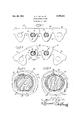
- Fig. 1 is a side elevational view of a silent chain construction embodying the features of the present invention, and with some of the parts thereof shown in section to more clearly illustrate the constructionv thereof and the relative disposition of parts when the chain is not flexed;
- Fig. 2 is a side elevational view of a silent chain construction depicted in Fig. l but showing the relative disposition of the parts thereof when the chain is in a flexed position;
- Fig. 3 is a fragmentary view of the automatic slack take-up assembly contemplated by this invention and illustrates the relative disposition of the parts when a load is placed upon the chain;
- Fig. 4' is a fragmentary sectional view of the automatic slack take-up assembly depicted in Fig. 3 and illustrates the relative disposition of the parts when no load is placed upon the chain.
- the illustrated silent chain construction may comprise a plurality of chain links 22, 23 and 24 interlaced in the conventional manner, the respective chain links being provided with toothed formations 26 adaptable for interengagement with suitable sprocket teeth (not shown).
- the illlustrated chain may have any desirable number of links to define a proper width of chain determined by the requirements of load.
- the pitch of the chain may be variable since the automatic slack take-up feature 29 contemplated by this invention may be advantageously employed on various sized silent chains.
- the silent chain. structure A including the automatic slack takeup assembly with which the present invention is particularly concerned comprises, in gen eral, a plurality of chain links, as at 22 23 and 24 interconnected by suitable pins 31] of identical construction, each of said pins having operatively associated therewith double linears 3!
- said double liners each defining bushings with a' curvature whose radii vary in lengthand are less than the diameter of their associated pin so that, when load is placed upon the chain, the pin is forced to nest in the bushing by deflecting the curvature of the bushing, the foregoing construction being particularly characterized in its operation by a spring action of each joint responsive to the load placed upon the chain.
- vature of the bushings whose radii vary will determine a plurality of focal points or centers of curvature which are different from the center of curvature or axis of the pin when the load is not on the chain; that the focal points of the bushing will coincide with the axis of the pin when the maximum load is placed on the chain; and that the location of the focal points of the bushing with respect to each other and to the axis of the pin will vary depending upon the magnitude of the loadplaced on the chain.
- the pins are arranged so that they are free to float in order to advantageously accommodate the flexure of the chain to various positions required.
- each of the chain links are provided. with suitable apertures as at and since the respective apertures are all similar in construction, it is deemed expedient to only describe one in detail.
- the aperture 35 is provided with in-. wardly projecting protuberances defining stops 35 and 31 arranged so that the bushings 3
- Fig. 1 wherein the subject construction is. shown in, its
- FIG. 2 wherein the relative disposition of the bushings 3
- the automatic slack take-up assembly with which the present invention is particularly concerned, provides the important feature of presenting the flexing action of the chain in a proper operating position in the line of the path of the load placed upon the chain, thereby to accommodate varying degrees of fiexure of the chain in its operation in connection with power transmission equipment.
- FIG. 3 is a fragmentary view of the automatic slack take-up assembly 20 contemplated by this invention and illustrates the relative disposition of the parts when a load is placed upon the chain. It
- a fragmentary sectional elevational view of the automatic slack take-up assembly 20 illustrates the relative disposition of the parts when there is no load upon the chain. This may be the condition of the chain on the loose side of the chain after it has left the driving sprocket, while the disposition of the parts illustrated in Fig. 3 illustrate their respective positions on the tight side of the chain during driving operation of the chain. It can be seen that the automatic slack take-up assembly contemplated by this invention will effectively reduce vibration and substantially eliminate objectionable noise which, heretofore, was present on the loose side of silent chains.
- the spring action of the automatic slack take-up assembly 20 may be effectively and advantageously controlled design-wise by the proper and judicious selection of a particular size of pin and a particular bushing curvature.
- the load required to force a selected pin to nest in a selected bushing may be effectively and advantageously controlled by the proper and judicious determination of the thickness of the bushing.
- a silent chain structure including an automatic slack take-up assembly, comprising a plurality of chain links interconnected by pins of identical construction, each of said pins having operatively associated therewith double liners each defining a bushing with a curvature whose radii vary in length and are less than the diameter of their associated pin and arranged so that the pin is forced to nest in the bushing by deflecting the curvature of the bushing when load is placed upon the chain, said arrangement being particularly characterized in its operation by a spring action of each joint responsive to the load place upon the chain.
- a silent chain structure including an automatic slack take-up assembly, comprising a plurality of chain links, a plurality of pins of identical construction operatively associated with said chain links to interconnect the same, and bushing means operatively associated with each pin and having a curvature whose radii vary in length and are less than the diameter of a respective associated pin, said arrangement being particularly characterized in its operation whereby the pin is forced to nest in the bushing by deflecting the curvature of the bushing when a load is placed upon the chain, thereby imparting a spring action at each joint of the chain responsive to the load placed upon the chain.
- a slack take-up assembly for silent chains having pins for interconnecting the chain links, comprising bushing means operatively associated with each pin and having a peripheral curvature different from the peripheral curvature of a respective associated pin and arranged so that the bushing has two points of abutment with said pin which determine a volume defined by noncontiguous areas of said pin and said bushing between said points of abutment, said volume being equal throughout the length of the bushing and varying in accordance with the magnitude of the load on said chain.
- An automatic slack take-up assembly for silent chains having pins for interconnecting the chain links comprising, bushing means operatively associated with each pin and having a curvature having radii determining focal points different from points on the axis of the bushing, said radii being less than the diameter of a respective associated pin, means associated with the chain links'for causing the bushing to revolve around their respective associated pin within range of the flexure of the chain, thereby to follow the path of the load upon the chain, said arrangement being particularly characterized in its operation whereby a respective pin is forced to nest in the bushing by deflecting the curvature of the bushing when load is placed upon the chain, thereby imparting a spring action at each joint of the chain responsive to the load placed upon the chain.
- double bushing means operatively associated with each pin and having a peripheral curvature different from the peripheral curvature of a respective associated pin and arranged so that said bushing has two contiguous lines with said pin defining an area of non-contiguity with said pin at the extreme position wherein no load is on the chain, said area of non-contiguity being equal throughout the length of the bushing and varying with the magnitude of the load on the chain, said bushing being completely contiguous with said pin at the other extreme position when maximum load is placed on the chain.
- pin for interconnecting the chain links, double bushing means operatively associated with each pin and having a curvature whose radii vary in length and are less than the diameter of a respective associated pin, together with means. associated, with the chain links for causing the bushing to revolve around their respective associated pin within range of the fiexure of the chain, thereby to follow the path of the load upon the chain, said arrangement being particularly characterized in its operation whereby a respective pin is forced to nest in the bushing by deflecting the curvature of the bushing when load is placed upon the chain, thereby imparting a spring action at each joint of the chain responsive to the load placed upon the chain.
- a silent chain structure including an automatic slack take-up assembly
- a slack take-up assembly for silent chains having pins for interconnecting the chain links, comprising bushing means operatively associated with each pin and having a curvature whose radii vary in length and determine centers of curvature which define lines parallel to the axis of the pin in one extreme position less than the diameter of a respective associated pin and arranged so that the pin is forced to nest in the bushing by deflecting the curvature of the bushing thereby causing the lines defined by the center of curvature of the bushing to coincide with the axis of the pin in a second extreme position when maximum load is placed upon the chain, and wherein the spring take-up action thereof is controlled design-wise by the dinerence in the curvature of the pin and bushing curvature and wherein the magnitude of the load required to force the pin to nest in the bushing is controlled by the thickness of the bushing so that the location of said lines determined by the center of curvature of the bushing varies between said extreme positions.
- a silent chain structure including an auto.- matic slack take-up assembly, comprising a plurality of. chain links, a plurality of pins of identical construction operatively associated with said chain links to interconnect the same, and bushing means operatively associated. with each. pin and having a curvature whose radii vary in length and determine centers of curvature which define lines parallel to the axis of the pin in one extreme position, said radii being less than the diameter of a respective associated pin, said arrangement being particularly characterized in its operation where by the pin i forced to.
Landscapes
- Engineering & Computer Science (AREA)
- General Engineering & Computer Science (AREA)
- Mechanical Engineering (AREA)
- Devices For Conveying Motion By Means Of Endless Flexible Members (AREA)
Description
Oct. 20, 1953 E. F. RIOPELLE SPRING BUSHED CHAIN Fi led May 21, 1949 Patented Oct. 20, 1953 SPRING BUSHED CHAIN Earl F. Riopelle, Detroit, lvlich assignor to Morse Chain Company, Ithaca, N. Y., a corporation of New York Application May 21, 1949, Serial No. 94,661
11 Claims. 1
This invention relates, in general, to chain constructions advantageously employed for power transmission equipment and is particularly concerned with silent chains providing a means for automatic slack take-up.
A silent chain construction incorporating an automatic slack take-up as contemplated by this invention is particularly advantageous because it eliminates the necessity of accurate and fine adjustments as to the length of the chain when first installed and substantially relieves the necessity of periodic adjustment to compensate for wear and. other variable factors involved in power transmission equipment. Moreover, the chain will always have proper tension which will eliminate vibration and objectionable noise in the operation thereof.
It is recognized that in the prior art numerous attempts have been made to provide a silent chain incorporating an automatic slack take-up feature of this general class and efforts have been made to overcome the various deficiencies found in such prior art structures, but to the best of the applicants knowledge the prior art structures have had only limited success, and have been accorded only limited recognition. It is believed that this fact results from apparent deficiencies of the prior art structures, their nonadaptability for universal application and their expensive construction which so greatly increased the cost as to seriously handicap sales acceptance.
The present improvements in silent chains, particularly characterized as having the auto matic slack take-up feature contemplated by this invention, are directed to simplify their construction and their mode of operation and also to provide a silent chain construction, incorporating the aforementioned features, which may readily and conveniently be employed universally to various types and sizes of silent chains presently employed. Moreover, the present device seeks to employ conventional parts wherever necessary and expedient, thereby. to effect a substantial reduction in cost over prevailing types of silent chains of this general class.
Accordingly, an object and accomplishment of the invention is to provide a silent chain construction comprising a plurality of chain links interconnected by suitable pins, said pins having operatively associated therewith double liners, said double liners defining bushings with a curvature whose radii vary and are less than the diameter of the pin so that, as the chain is loaded, the pin is forced to nest in the bushing by defleeting or decreasing the curvature of the bushing, the foregoing construction being particularly characterized in its operation by a spring action of each joint.
A further object and accomplishment of the invention is to provide a silent chain construction incorporating the feature of an automatic slack take-up hereinbefore described and wherein the spring action, or take-up, is controlled designwise by the difference in the curvature of the pin and bushing curvature and wherein the load required to force the pin to nest in the bushing is controlled by the thickness of the bushing.
Another object and accomplishment of the invention is to provide an automatic slack take-up for incorporation in silent chains, said automatic slack take-up being designed for advantageous employment in power transmission equipment and which shall have a novel and compact arrangement of parts wherein said parts can be readily assembled and serviced.
The invention seeks, as a further object and accomplishment, to provide a silent chain construction incorporating an automatic slack takeup as contemplated herein and characterized by an arrangement of parts to more advantageously and satisfactorily perform the function required of it and adapted to provide a compact unit which will successfully combine the factors of structural simplicity and durability, and yet be economical to manufacture.
An important object and accomplishment of the invention is to provide an automatic slack take-up for silent chains, said automatic slack take-up being particularly and advantageously applicable for employment in power transmission equipment where freedom from vibration and objectionable noise is desired, said automatic slack take-up being particularly characterized in its simple but sturdy construction and in its convenient fool-proof and safe operation.
Another particular object and accomplishment of the invention is to provide a silent chain having an automatic slack take-up by co-relating and especially designing the various elements of such automatic slack take-up whereby there shall be cooperation between said improved elements as will best serve the purpose of providing an ef. ficient silent chain construction capable of being manufactured at low cost and yet giving the maximum of service in use.
Additional objects, features and advantages of the invention disclosed herein will be apparent to persons skilled in the art after the construction and operation are understood from the within de scription.
It is preferred to accomplish the various objects of the invention and to practice the same in substantially the manner as hereinafter more fully described, and, as more particularly pointed out in the appended claims.
With the above and other incidental objects in view, the invention has other marked improvements and superiorities which radically distinguishes it from presently known structures, these improvements in the invention residing in the novel construction and the cooperating function of the parts thereof, the combination of parts and the arrangement thereof as illustrated in the drawing and which will be more fully described, hereinafter and particularly pointed out in the claims.
In the accompanying drawing on which there are preferred embodiments of the invention,
Fig. 1 is a side elevational view of a silent chain construction embodying the features of the present invention, and with some of the parts thereof shown in section to more clearly illustrate the constructionv thereof and the relative disposition of parts when the chain is not flexed;
Fig. 2 is a side elevational view of a silent chain construction depicted in Fig. l but showing the relative disposition of the parts thereof when the chain is in a flexed position;
Fig. 3 is a fragmentary view of the automatic slack take-up assembly contemplated by this invention and illustrates the relative disposition of the parts when a load is placed upon the chain; and
Fig. 4' is a fragmentary sectional view of the automatic slack take-up assembly depicted in Fig. 3 and illustrates the relative disposition of the parts when no load is placed upon the chain.
The drawing is to be understood as being more or less of a schematic character for the purpose of illustrating or disclosing typical or preferred forms of the improvements contemplated herein and in the drawing like reference characters identify the same parts in the several views.
As one possible example of advantageous employment of the contemplated automatic slack take-up assembly, reference is made to the drawing wherein there is illustrated a silent chain construction having incorporated therein the especially designed automatic slack take-up assembly with which the invention is particularly concerned and designated in its entirety by the numeral 20 as being operatively associated with a conventional silent chain designated in its entirety by the letter A, said silent chain A being adjunctively employed, for example, to conventional' power transmission equipment (not shown) which may include timing chains for automotive vehicles but is not necessarily limited to the suggested application thereof.
The illustrated silent chain construction may comprise a plurality of chain links 22, 23 and 24 interlaced in the conventional manner, the respective chain links being provided with toothed formations 26 adaptable for interengagement with suitable sprocket teeth (not shown).
Although only the important sprocket links are illustrated for the. purpose of the explanation of. the operation of the. automatic slack take-up means, it is obvious that the illlustrated chain may have any desirable number of links to define a proper width of chain determined by the requirements of load. Moreover, the pitch of the chain may be variable since the automatic slack take-up feature 29 contemplated by this invention may be advantageously employed on various sized silent chains.
Suflice it to say, since the invention is not particularly concerned with the precise construction of the illlustrated silent chain structure and/or its associated parts, they will. not be furall ther described in detail, and it is deemed suiiicient for all intentions and purposes herein contained to show only portions thereof adjacent to and cooperating with the automatic slack takeup assembly 20. contemplated herein. It is to be understood that details of construction of such silent chains and/or their associated parts may be modified to suit particular conditions or to satisfy the engineering genius of various competitive. manufacturers and in some instances the automatic. slack take-up assembly contemplated herein may be advantageously employed in other types of chains, and I do not wish to be limited to the construction of these elements as set forth, except where such construction particularly relates to or is concerned with the invention contemplated herein.
Having thus described; by way of example, a possible adaptation of the automatic take-up assembly as contemplated herein and having described the general environment surrounding" the adaptation, the specific construction and 00- operating functions of the parts of said auto matic take-up assembly with which the present invention is particularly concerned, will now be described in detail.
In the exemplary embodiment of the inven tion depicted in Figs. 1 and 2, the silent chain. structure A including the automatic slack takeup assembly with which the present invention is particularly concerned comprises, in gen eral, a plurality of chain links, as at 22 23 and 24 interconnected by suitable pins 31] of identical construction, each of said pins having operatively associated therewith double linears 3! and 32, said double liners each defining bushings with a' curvature whose radii vary in lengthand are less than the diameter of their associated pin so that, when load is placed upon the chain, the pin is forced to nest in the bushing by deflecting the curvature of the bushing, the foregoing construction being particularly characterized in its operation by a spring action of each joint responsive to the load placed upon the chain. Thus it can be seen; that the cur! vature of the bushings whose radii vary will determine a plurality of focal points or centers of curvature which are different from the center of curvature or axis of the pin when the load is not on the chain; that the focal points of the bushing will coincide with the axis of the pin when the maximum load is placed on the chain; and that the location of the focal points of the bushing with respect to each other and to the axis of the pin will vary depending upon the magnitude of the loadplaced on the chain.
In accordance with the construction of the present invention the pins are arranged so that they are free to float in order to advantageously accommodate the flexure of the chain to various positions required.
In adverting to Figs. 1. and 2, it can be seen that each of the chain links are provided. with suitable apertures as at and since the respective apertures are all similar in construction, it is deemed expedient to only describe one in detail. For example, the aperture 35 is provided with in-. wardly projecting protuberances defining stops 35 and 31 arranged so that the bushings 3| and 32' may be held in theirrespective operative posi- 7 tion and, more important, to provide a means for causing the bushings to revolve around the pin, in a restricted. sense, to follow the path of the load. This action is clearly illustrated in Fig. 1 wherein the subject construction is. shown in, its
straight line position and it can be seen that the bushings 3| and 32 are disposed in the direct line of the pull which would be either to the left or to the right of the chain construction disclosed in Fig. 1.
Particular attention is invited to Fig. 2 wherein the relative disposition of the bushings 3| and 32, when the chain is in its flexed position, is such that the bushings are again in the path of the load.
In operation, the movement of the respective bushings 3| and 32 is accomplished by the particular disposition of the stops 36 and 31 so that in one link (Fig. 1) a portion 31a of the stop 3'! will cause the rotation about the axis of the pin 30 of the bushing 32 when the chain is flexed as shown in Fig. 2. In Fig. 2, it can be seen that the portion 31b of the stop 31 which, incidentally, is disposed in the link 23 reacts. upon the bushing 3! to move it into its proper operative position in line with the path of the load upon the chain.
Thus, it can be seen that the automatic slack take-up assembly with which the present invention is particularly concerned, provides the important feature of presenting the flexing action of the chain in a proper operating position in the line of the path of the load placed upon the chain, thereby to accommodate varying degrees of fiexure of the chain in its operation in connection with power transmission equipment.
Particular attention is invited to Fig. 3 which is a fragmentary view of the automatic slack take-up assembly 20 contemplated by this invention and illustrates the relative disposition of the parts when a load is placed upon the chain. It
can be seen that the bushings 3| and 32 tend to hug the pin to provide a solid drive connection throughout the chain.
In Fig. 4 a fragmentary sectional elevational view of the automatic slack take-up assembly 20 illustrates the relative disposition of the parts when there is no load upon the chain. This may be the condition of the chain on the loose side of the chain after it has left the driving sprocket, while the disposition of the parts illustrated in Fig. 3 illustrate their respective positions on the tight side of the chain during driving operation of the chain. It can be seen that the automatic slack take-up assembly contemplated by this invention will effectively reduce vibration and substantially eliminate objectionable noise which, heretofore, was present on the loose side of silent chains.
It is notable that the spring action of the automatic slack take-up assembly 20 may be effectively and advantageously controlled design-wise by the proper and judicious selection of a particular size of pin and a particular bushing curvature. Moreover, the load required to force a selected pin to nest in a selected bushing may be effectively and advantageously controlled by the proper and judicious determination of the thickness of the bushing.
In accordance with the construction of the present invention the parts and their relative disposition effectively provide a compact arrangement of parts which can be readily assembled and serviced. This is an important feature in that chains of this type must, of necessity, be produced under mass production manufacturing principles.
From the foregoing disclosures it may be observed that I have provided an improved silent chain construction including an automatic slack take-up feature which effectively fulfills the ob jects thereof as hereinbefore set forth and which provides numerous: advantages which may be summarized as follows:
1. Structurally simple, eificient and durable;
2. Economical to manufacture and readily adaptable to mass production manufacturing principles; and
3. The provision of an improved automatic slack take-up assembly particularly and advantageously applicable for employment in power transmission equipment where freedom from. vibration and objectionable noise is desired.
While I have illustrated a preferred embodiment of my invention, many modifications may be made without departing from the spirit of the invention, and I do not Wish to be limited to the precise details of construction set forth but wish to avail myself of all changes within the scope of the appended claims.
I claim:
1. A silent chain structure including an automatic slack take-up assembly, comprising a plurality of chain links interconnected by pins of identical construction, each of said pins having operatively associated therewith double liners each defining a bushing with a curvature whose radii vary in length and are less than the diameter of their associated pin and arranged so that the pin is forced to nest in the bushing by deflecting the curvature of the bushing when load is placed upon the chain, said arrangement being particularly characterized in its operation by a spring action of each joint responsive to the load place upon the chain.
2. A silent chain structure including an automatic slack take-up assembly, comprising a plurality of chain links, a plurality of pins of identical construction operatively associated with said chain links to interconnect the same, and bushing means operatively associated with each pin and having a curvature whose radii vary in length and are less than the diameter of a respective associated pin, said arrangement being particularly characterized in its operation whereby the pin is forced to nest in the bushing by deflecting the curvature of the bushing when a load is placed upon the chain, thereby imparting a spring action at each joint of the chain responsive to the load placed upon the chain.
3. A slack take-up assembly for silent chains having pins for interconnecting the chain links, comprising bushing means operatively associated with each pin and having a peripheral curvature different from the peripheral curvature of a respective associated pin and arranged so that the bushing has two points of abutment with said pin which determine a volume defined by noncontiguous areas of said pin and said bushing between said points of abutment, said volume being equal throughout the length of the bushing and varying in accordance with the magnitude of the load on said chain.
a. An automatic slack take-up assembly for silent chains having pins for interconnecting the chain links, comprising, bushing means operatively associated with each pin and having a curvature having radii determining focal points different from points on the axis of the bushing, said radii being less than the diameter of a respective associated pin, means associated with the chain links'for causing the bushing to revolve around their respective associated pin within range of the flexure of the chain, thereby to follow the path of the load upon the chain, said arrangement being particularly characterized in its operation whereby a respective pin is forced to nest in the bushing by deflecting the curvature of the bushing when load is placed upon the chain, thereby imparting a spring action at each joint of the chain responsive to the load placed upon the chain.
5. In a slack take-up assembly for silent chains having pins for interconnecting the chain links, double bushing means operatively associated with each pin and having a peripheral curvature different from the peripheral curvature of a respective associated pin and arranged so that said bushing has two contiguous lines with said pin defining an area of non-contiguity with said pin at the extreme position wherein no load is on the chain, said area of non-contiguity being equal throughout the length of the bushing and varying with the magnitude of the load on the chain, said bushing being completely contiguous with said pin at the other extreme position when maximum load is placed on the chain.
6. In an automatic slack take-up assembly for silent chains, pin for interconnecting the chain links, double bushing means operatively associated with each pin and having a curvature whose radii vary in length and are less than the diameter of a respective associated pin, together with means. associated, with the chain links for causing the bushing to revolve around their respective associated pin within range of the fiexure of the chain, thereby to follow the path of the load upon the chain, said arrangement being particularly characterized in its operation whereby a respective pin is forced to nest in the bushing by deflecting the curvature of the bushing when load is placed upon the chain, thereby imparting a spring action at each joint of the chain responsive to the load placed upon the chain.
7. In a silent chain structure including an automatic slack take-up assembly, the combination of a plurality of chain links, pins of identical construction for interconnecting said chain links, and double liners each defining a bushing with a curvature whose radii vary in length and are less than the diameter of their associated pin and arranged so that the pin is forced to nest in the bushing by deflecting the curvature of the bushing when load is placed upon the chain.
8-. In an automatic slack take-up assembly for silent chains having pins for interconnecting the chain links, the combination of bushing means operative 3: associated with each pin and having a curvature whose radii vary in length and are less than the diameter of a respective associated pin, and means associated with the chain links for causing thebushing to revolve around their respective associated pin Within range of the flexure of the chain, thereby to follow the path of the load upon the chain.
. 9. A slack take-up assembly for silent chains having pins for interconnecting the chain links, comprising bushing means operatively associated with each pin and having a curvature whose radii vary in length and determine centers of curvature which define lines parallel to the axis of the pin in one extreme position less than the diameter of a respective associated pin and arranged so that the pin is forced to nest in the bushing by deflecting the curvature of the bushing thereby causing the lines defined by the center of curvature of the bushing to coincide with the axis of the pin in a second extreme position when maximum load is placed upon the chain, and wherein the spring take-up action thereof is controlled design-wise by the dinerence in the curvature of the pin and bushing curvature and wherein the magnitude of the load required to force the pin to nest in the bushing is controlled by the thickness of the bushing so that the location of said lines determined by the center of curvature of the bushing varies between said extreme positions.
10. In an automatic slack take-up assembly for silent chains having pins for interconnecting the chain links, the combination of bushing means operatively associated with each pin and having a curvature whose radii vary in length and determine centers of curvature which define lines parallel to the axis of the pin in one extreme position and are less than the diameter of a respective associated pin and arranged so that the pin is forced to nest in the bushing by deflecting the curvature of the bushing thereby causing the lines defined by the center of curvature to coincide with the axis of the pin in a second extreme position when maximum load is placed on the chain, and, means associated with the chain links for causing the bushing means to revolve around their respective associated pin within the range of the flexure of the chain, thereby to follow the load upon the chain, and wherein the spring take-up action thereof is controlled design-wise by the difierence in the curvature of the pin and bushing curvature and wherein the magnitude of the load required to force the pin to nest in the bushing is controlled by the thickness of the bushing thereby varying the locations of the lines determined by the center of curvature between said extreme positions.
11. A silent chain structure including an auto.- matic slack take-up assembly, comprising a plurality of. chain links, a plurality of pins of identical construction operatively associated with said chain links to interconnect the same, and bushing means operatively associated. with each. pin and having a curvature whose radii vary in length and determine centers of curvature which define lines parallel to the axis of the pin in one extreme position, said radii being less than the diameter of a respective associated pin, said arrangement being particularly characterized in its operation where by the pin i forced to. nest in the bushing by deflecting the curvature of the bushing thereby causing the lines defined by the centers of curvature to coincide with the axis of the pin in a second extreme position when a maximum load is placed upon the chain, thereby imparting a spring action at each joint of the chain responsive to the load placed upon the chain, and wherein the spring take-up action thereof is controlled. design-wise by the difference in the curvature of the pin and bushing curvature and wherein the load required to force the pin tonest in the bushing is controlled by the thickness of the bushing thereby varying the location of the lines determined by the centers of curvature between extreme positions.
EARL F. RIOPELLE.
References Cited in the file of this patent UNITED STATES PATENTS Number Name Date 1,384,173 Wikander July 12, 1921 1,419,891 Oakes June 13, 1922 1,780,040 Pierce Oct. 28, 1930 2,047,833 Pierce July 14, 1936 2,324,640. Perry July 20, 1943 2,415,188 Olander Feb. 4;, 1947
Priority Applications (1)
| Application Number | Priority Date | Filing Date | Title |
|---|---|---|---|
| US94661A US2655816A (en) | 1949-05-21 | 1949-05-21 | Spring bushed chain |
Applications Claiming Priority (1)
| Application Number | Priority Date | Filing Date | Title |
|---|---|---|---|
| US94661A US2655816A (en) | 1949-05-21 | 1949-05-21 | Spring bushed chain |
Publications (1)
| Publication Number | Publication Date |
|---|---|
| US2655816A true US2655816A (en) | 1953-10-20 |
Family
ID=22246429
Family Applications (1)
| Application Number | Title | Priority Date | Filing Date |
|---|---|---|---|
| US94661A Expired - Lifetime US2655816A (en) | 1949-05-21 | 1949-05-21 | Spring bushed chain |
Country Status (1)
| Country | Link |
|---|---|
| US (1) | US2655816A (en) |
Cited By (3)
| Publication number | Priority date | Publication date | Assignee | Title |
|---|---|---|---|---|
| US4704099A (en) * | 1984-08-09 | 1987-11-03 | Bernhard Rohloff | Roller chain for chain drives |
| US5147250A (en) * | 1991-06-13 | 1992-09-15 | Borg-Warner Automotive Transmission & Engine Components Corporation | Chain design |
| EP1053412A4 (en) * | 1998-02-10 | 2005-07-13 | Mesh Company Llc | Short pitch tooth chain |
Citations (6)
| Publication number | Priority date | Publication date | Assignee | Title |
|---|---|---|---|---|
| US1384173A (en) * | 1918-05-10 | 1921-07-12 | S K F Ball Bearing Company | Flexible bushing |
| US1419891A (en) * | 1921-06-01 | 1922-06-13 | Link Belt Co | Chain |
| US1780040A (en) * | 1926-09-11 | 1930-10-28 | Link Belt Co | Drive chain |
| US2047833A (en) * | 1934-10-10 | 1936-07-14 | Link Belt Co | Power transmission chain |
| US2324640A (en) * | 1942-01-19 | 1943-07-20 | Morse Chain Co | Chain |
| US2415188A (en) * | 1943-05-24 | 1947-02-04 | Miner Inc W H | Shock absorber |
-
1949
- 1949-05-21 US US94661A patent/US2655816A/en not_active Expired - Lifetime
Patent Citations (6)
| Publication number | Priority date | Publication date | Assignee | Title |
|---|---|---|---|---|
| US1384173A (en) * | 1918-05-10 | 1921-07-12 | S K F Ball Bearing Company | Flexible bushing |
| US1419891A (en) * | 1921-06-01 | 1922-06-13 | Link Belt Co | Chain |
| US1780040A (en) * | 1926-09-11 | 1930-10-28 | Link Belt Co | Drive chain |
| US2047833A (en) * | 1934-10-10 | 1936-07-14 | Link Belt Co | Power transmission chain |
| US2324640A (en) * | 1942-01-19 | 1943-07-20 | Morse Chain Co | Chain |
| US2415188A (en) * | 1943-05-24 | 1947-02-04 | Miner Inc W H | Shock absorber |
Cited By (3)
| Publication number | Priority date | Publication date | Assignee | Title |
|---|---|---|---|---|
| US4704099A (en) * | 1984-08-09 | 1987-11-03 | Bernhard Rohloff | Roller chain for chain drives |
| US5147250A (en) * | 1991-06-13 | 1992-09-15 | Borg-Warner Automotive Transmission & Engine Components Corporation | Chain design |
| EP1053412A4 (en) * | 1998-02-10 | 2005-07-13 | Mesh Company Llc | Short pitch tooth chain |
Similar Documents
| Publication | Publication Date | Title |
|---|---|---|
| US2667791A (en) | Silent chain | |
| US2725755A (en) | Power transmission chain drive | |
| US3276282A (en) | Tensioning devices | |
| EP3477154B1 (en) | Clamping device | |
| US10295025B2 (en) | Belt transmission system | |
| CN108458069A (en) | A kind of big damping automatic tensioner of variation rigidity | |
| EP2000699A2 (en) | Torque oscillation attenuator or decoupler with coiled wire springs in a drive disc | |
| US2655816A (en) | Spring bushed chain | |
| US3019622A (en) | Flexible coupling | |
| US1693431A (en) | Drive chain | |
| US2047833A (en) | Power transmission chain | |
| US1780040A (en) | Drive chain | |
| US2324640A (en) | Chain | |
| US2909938A (en) | Drive chain | |
| US1967052A (en) | Vibration cushioning driving device | |
| US1670278A (en) | Silent-chain drive | |
| US1496298A (en) | Connecting link for drive chains | |
| US20070142150A1 (en) | Link plate for a plate-link chain | |
| US1570274A (en) | Power-transmission chain | |
| US2415278A (en) | Spur gear drive transmission | |
| US2678569A (en) | Power transmission chain | |
| US1264193A (en) | Elastic belt. | |
| US1704279A (en) | Drive chain | |
| US1371512A (en) | Pulley-adapter | |
| US1465946A (en) | Power-transmission chain |